24
RAUSPEED MICRODUCT SYSTEM FOR THE AREA OF APPLICATION “FIBRE TO THE X” Construction Automotive Industry Valid from August 2014 Subject to technical modifications www.rehau.com

RAUSPEED MICRODUCT SYSTEMFOR THE AREA OF APPLICATION “FIBRE TO THE X”
ConstructionAutomotive
Industry
Valid from August 2014Subject to technical modificationswww.rehau.com

Aufgrund einer Systemumstellung auf SAP haben sich 2012 unsere Artikelnummern auf Materialnummern geändert.
Die bisherige Artikelnummer wurde zur Materialnummer und um 2 Stellen erweitert: alt: 123456-789 (Artikelnummer)neu: 11234561789 (Materialnummer)
Um dies abzubilden, haben wir die erweiterten Stellen optisch gekennzeichnet: 1 = 1, z.B.: 11234561789
Wir bitten um Verständnis, dass systemtechnisch alle Angebote, Auftragsbestätigungen, Versandscheine und Rechnungen weitgehend nur mit der 11-stelligen Nummer versandt werden.
Due to a system conversion to SAP in 2012, our article numbers have changed to material numbers.
The previous article numbers have become material numbers with 2 extra digits: old: 123456-789 (article number)new: 11234561789 (material number)To illustrate this, we have visually identified the additional digits: 1 = 1, e.g.: 11234561789
Please note that in the system all quotations, order confirmations, dispatch notes and invoices will largely only be issued with the 11-digit number.
En raison de la conversion de nos systèmes informatiques vers SAP, nos numéros d’articles ont changé en numéros de matière en 2012.
Le numéro d’article existant est devenu un numéro de matière qui a deux chiffres de plus : ancien : 123456-789 (numéro d’article)nouveau : 11234561789 (numéro de matière)Afin de visualiser ces chiffres d’extension, nous les avons mis en relief : 1 = 1, p. ex. : 11234561789
Nous comptons sur votre compréhension pour le fait que tous nos offres, accusés de réception de commande, bordereaux de livraison et factures porteront pour une grande partie uniquement le nouveau numéro à 11 chiffres.
Aufgrund einer Systemumstellung auf SAP haben sich 2012 unsere Artikelnummern auf Materialnummern geändert.
Die bisherige Artikelnummer wurde zur Materialnummer und um 1 Stelle erweitert: alt: 123456 (Artikelnummer)neu: 1123456 (Materialnummer)
Um dies abzubilden, haben wir die erweiterten Stellen optisch gekennzeichnet: 1 = 1, z.B.: 1123456
Wir bitten um Verständnis, dass systemtechnisch alle Angebote, Auftragsbestätigungen, Versandscheine und Rechnungen weitgehend nur mit der 7-stelligen Nummer versandt werden.
Due to a system conversion to SAP in 2012, our article numbers have changed to material numbers.
The previous article numbers have become material numbers with 1 extra digit: old: 123456 (article number)new: 1123456 (material number)To illustrate this, we have visually identified the additional digits: 1 = 1, e.g.: 1123456
Please note that in the system all quotations, order confirmations, dispatch notes and invoices will largely only be issued with the 7-digit number.
En raison de la conversion de nos systèmes informatiques vers SAP, nos numéros d’articles ont changé en numéros de matière en 2012.
Le numéro d’article existant est devenu un numéro de matière qui a un chiffre de plus : ancien : 123456 (numéro d’article)nouveau : 1123456 (numéro de matière)Afin de visualiser ce chiffre d’extension, nous l’avons mis en relief : 1 = 1, p. ex. : 1123456
Nous comptons sur votre compréhension pour le fait que tous nos offres, accusés de réception de commande, bordereaux de livraison et factures porteront pour une grande partie uniquement le nouveau numéro à 7 chiffres.
Materialmerksaetze 10 pt 2013-04-02.indd 1 10.04.2013 09:39:02
CONTENTSMICRODUCT SYSTEM FOR THE AREA OF APPLICATION “FIBRE TO THE X”
1 Scope 3
2 Area of application 3
3 Materials 33.1 . . . . Microduct . . . . . . . . . . . . . . . . . . . . . . . . . . 33.2 . . . . Bundle coat material . . . . . . . . . . . . . . . . . . . . . 3
4 Identification 44.1 . . . . RAUSPEED microduct . . . . . . . . . . . . . . . . . . . . . 44.2 . . . . RAUSPEED bundle . . . . . . . . . . . . . . . . . . . . . . 4
5 Delivery format 5
6 Product range RAUSPEED microduct system 66.1 . . . . RAUSPEED Microducts and duct bundles . . . . . . . . . . . 66.2 . . . . RAUSPEED Fittings . . . . . . . . . . . . . . . . . . . . . . 86.3 . . . . RAUSPEED Accessories . . . . . . . . . . . . . . . . . . . 126.4 . . . . Accessories for cable ducts . . . . . . . . . . . . . . . . . 136.5 . . . . RAUSPEED Tools . . . . . . . . . . . . . . . . . . . . . . 14
7 Planning and installation 18
2

1 Scope
This document is applicable for the material properties, dimensions, make-up for delivery, design and installation of REHAU RAUSPEED microduct systems made from PE-HD (high density polyethylene) as well as the associated fittings.
2 Area of application
The increasing use of optical fibre-based high-speed data networks in global communications technology means that new system components are cons-tantly being required for installing, connecting and operating them.Over the coming years, development and economic projects will equip areas with powerful broadband systems they have so far been without. This applies to both industrial areas as well as private households where, with a connection, high-definition 3D and HD TV, online gaming in real time, HD video calling and lightning quick internet, according to the current claim of 200 Mbit/s per download and 100 Mbit/s per upload, is possible.
REHAU has expanded its product portfolio in the area of telecommunication accordingly and can now supply the “last mile” as a global player in the area of “FTTX”.
There are several interim steps on the route to complete supply with optical fibre cables, which envisage a combination of copper cables and optical fibre cables:
FTTC – Fibre to the Curb“Installing optical fibres at the curb”Installing the optical fibres as far as the next terminal, the cable branch pointFTTB – Fibre to the Building“Installing optical fibres as far as the building”FTTH – Fibre to the Home “Installing optical fibres as far as the house”.
In the case of FTTH installation, the optical fibre cables run right up to the end customer‘s subscriber terminal. As a result of this, transfer rates of up to 1000 Mbit/s are possible.In order to achieve FTTH, an optical fibre cable is required that has the visual properties of an optical fibre cable and the flexibility of copper cables. In the application areas of FTTH, significantly smaller radii are being encountered than with conventional optical fibre installations. The cable must meet that standard ITU-T-G.657.
For the various optical fibre network architectures, there are different transfer technologies and systems that bridge the gap between the exchange and subscriber terminal with an appropriate combination of optical fibre and copper cables. In distribution networks, the flexible upgradability in line with requirement is especially important.This includes the simple and quick branching and connection possibilities to supply the end customer. In addition to this, the ability to split the transfer ca-pacity to various, in network planning often completely unknown connections is of particular significance. The micro cable or glass fibre bundles facilitate this flexible development in conjunction with the microducts. Many advantages can be achieved with microducts both when setting up new cable networks, in particular distribution networks, as well as when using existing empty sections of duct: - Sophisticated jointing technique including tools - Fittings and accessories product range - Maximum flexibility - Can be adjusted to any requirement - Individual identification options
Microduct variants for direct installation into the ground or installation into the protective sleeve - Single duct and bundled variants possible - Can be fitted with mini cables, micro cables and blown fibre - Extensive accessories product range
The pressure-tight design of the microduct systems and fittings and the interior surface of the microducts with the special REHAU trapezoidal grooving enable a particularly cost-effective installation of cables through blowing in with compressed air.
3 Materials
3 1 Microduct
The microducts are manufactured from RAU-PE.Material properties at 23 °C:RAU-PE 3204:Average density: > 0.94 g/cm³Coefficient of linear expansion: 2.0 × 10⁻⁴ K-1Thermal conductivity: 0.41 WK-1m-1Modulus of elasticity: Short-term: min. 800 N/mm² Long-term: min. 160 N/mm²Spec. surface resistance: > 10^12 Ω Fire behavior:RAU-PE has normal flame-resistance to DIN 4102, Building material class B2Pressure test 170 h / 80 °C / 4 N/mm²
3 2 Bundle coat material
The bundle is made from RAU-PP. Average density: > 0.9 g/cm3Coefficient of linear expansion: 1.4 × 10⁻⁴ K-1Thermal conductivity: 0.2 WK-1 m-1Modulus of elasticity: Short-term: min. 1250 N/mm2 Long-term: min. 310 N/mm²Spec. surface resistance: > 10^12 Ω Fire behavior: RAU-PP has normal flame-resistance to DIN 4102, Building material class B2
KVz/MFG
Optical fibre cable Copper cable
KVz/MFG
3

4 Identification
4 1 RAUSPEED microduct
The microducts made from PE-HD are identified using permanent ink-jet printing at 1 m intervals with the following information:
Manufacturer and area of application: REHAU RAUSPEED Material: PE-HDDimensions in mm: e.g. 7 × 1.5 mmProduction date (Day, Month, Year): e.g. 16.07.2013Number of meters: e.g. 1254 mMachine
Translucent color to identify the allocation, with colored stripe identification in the colors blue, yellow, green, red, brown, purple, white, grey, black and orange. RTR Rehau trapezoidal grooving inside.
The technical properties meet the requirements of the German Telecoms.
For differentiation and recognition purposes, the microducts are marked with colored stripes and the corresponding duct number in the bundle. This is important, so that during the subsequent installation, each microduct can be clearly allocated to a building.
Duct number identification and color coding of the individual ducts in thebundle:
Duct No Colour combination Stripes in RAL 1 red/yellow RAL 3000/RAL 1018 2 red/green RAL 3000/RAL 6024 3 red/blue RAL 3000/RAL 5002 4 red/purple RAL 3000/RAL 4005 5 red/grey RAL 3000/RAL 7000 6 yellow/blue RAL 1018/RAL 5002 7 yellow/purple RAL 1018/RAL 4005 8 yellow/grey RAL 1018/RAL 7000 9 green/blue RAL 6024/RAL 500210 green/purple RAL 6024/RAL 400511 green/grey RAL 6024/RAL 700012 brown/blue RAL 8003/RAL 500213 brown/purple RAL 8003/RAL 400514 brown/grey RAL 8003/RAL 700015 brown/green RAL 8003/RAL 602416 brown/yellow RAL 8003/RAL 101817 brown/red RAL 8003/RAL 300018 black/red RAL 9005/RAL 300019 black/yellow RAL 9005/RAL 101820 black/green RAL 9005/RAL 602421 black/blue RAL 9005/RAL 500222 black/purple RAL 9005/RAL 400523 black/grey RAL 9005/RAL 700024 black/brown RAL 9005/RAL 800325 red/red RAL 3000/RAL 300026 red/red RAL 3000/RAL 3000
4 2 RAUSPEED bundle
The microduct bundles made from PP are identified using permanent ink-jet printing at 1 m intervals with the following information:Manufacturer and area of application: REHAU RAUSPEED Dimensions in mm: e.g. 24 × 7 × 1.5Production date (Day, Month, Year): e.g. 16.07.2013Number of meters: e.g. 0973 mMachineAdditional duct number identification (1 - 25) of the individual ducts at inter-vals of 10 cm
Exterior layer: PP, color black (colored on request)Bundle variants containing 2 to 24 ducts (25/26 ducts incl. central duct) Single ducts in the bundle from 7 to 20 mm
REHAU RAUSPEED 24 x 7 x 1.5Lettering:
[Date] [Metres] [Machine]
21 43
65 87
1110 1312
1716 1918
2221 2423
1514
9
20
4

Diameter
Core
Width
5 Delivery format
Due to their flexibility, the microduct systems are suitable for transport in long lengths on cable drums.Due to the low weight of the microduct systems, light wooden disposable drums are used for delivery.
Standard make-up for delivery on wooden drums:
Diameter Width Core Empty weight[mm] [mm] [mm] [kg]
Single duct 7 mm 700 380 485 14Single duct above 10 mm 1,200 380 485 20Single duct 20 mm 1,200 530 800 22For duct bundles 2,000 1,120 1,250 222
Microducts and duct bundlesYou will find more information in the product range under Point 6 of this Document.
Notes:During transport and handling of the cable drums, the familiar working and safety regulations are to be observed. When handling the cable drums on uneven ground, it is to be ensured that the coils do not become loose and that the duct does not drag across the ground.Resting the coiled lengths of duct on uneven ground is to be avoided without fail.
The tender texts for the individual microduct system dimensions can be provided on request.The tender texts can also be downloaded on the internet at www.rehau.com.
5

6 Product range RAUSPEED Microduct system
6 1 RAUSPEED Microducts and duct bundles
RAUSPEED MicroductsFor blowing in optical wave guide (LWL) cables.Material: PE-HD, transparent with identical colored stripes in blue, yellow, green, red, brown, purple, white, grey, black and orangeRTR REHAU trapezoidal groovingDIN 16874Direct installation into the ground is possible above a wall thickness of 1.5 mmFlame-retarding version on request.
Mat No Dimensions Outer diameter Internal diameter Supply lengths Weight Max blowing in pressure[mm] [mm] [m] [g/m] [bar]
11021761001 7 × 0.75 7 5.5 1,250 15 1011021771001 7 × 1.5 7 4 1,250 25 1611021781001 10 × 1.0 10 8 2,500 28 1011021851001 10 × 2.0 10 6 2,500 48 1611007381001 12 × 1.0 12 10 1,750 38 1011021861001 12 × 2.0 12 8 1,750 58 1611021871001 14 × 2.0 14 10 1,250 72 1611021881001 16 × 2.0 16 12 1,000 87 1011006851001 20 × 2.0 20 16 600 111 10
Other dimensions on request/delivery times to be agreed
6

RAUSPEED Duct bundlesBundle coat, allowing straight installation of single ducts (large blowing-in lengths)Exterior layer: PP, standard color black Different coloring possible, for better distinction in the trench.Inner single ducts PE-HD in different color combinations and corresponding duct numberDirect installation into ground possible above a wall thickness of 1.5 mm of single ducts wash boring version on request.
Mat No max OD Description Supply lengths Weight[mm] [m] [g/m]
11008821001* 15 2 x 7 x 1.5 2,000 / 450 7511037241001* 26 4 x 7 x 1.5 1,200 12511024341001* 26 6 x 7 x 1.5 750 18511037251001 26 7 x 7 x 1.5 750 18511032061001 22 8 x 7 x 1.5 3,000 24511032971001 22 10 x 7 x 1.5 2,500 29311021941001 31 12 x 7 x 1.5 1,800 39511037021001 40 12 x 7 x 1.5 + 1 x 14 x 2.0 1,300 43011021991001 34 14 x 7 x 1.5 1,500 47511004011001 37 18 x 7 x 1.5 1,200 59511022171001 43 22 x 7x 1.5 + 1 x 12 x 2.0 1,000 69011002741001 44 24 x 7 x 1.5 + 1 x 14 x 2.0 700 76011036851001 46 25 x 7 x 1.5 + 1 x 16 x 2.0 650 77311021951001 44 24 x 7 x 1.5 1,000 69011036691001* 22 2 x 10 x 2.0 1,200 12511028781001 36 6 x 10 x 2.0 1,950 33511022161001 42 12 x 10 x 2.0 950 66511006681001 38 5 x 12 x 1.0 1,300 23511006691001 38 7 x 12 x 1.0 1,000 31511006491001 26 2 x 12 x 2.0 1,900 18511003141001 26 3 x 12 x 2.0 2,000 23011022051001 32 4 x 12 x 2.0 2,000 29511006661001 38 5 x 12 x 2.0 1,300 33011022061001 38 7 x 12 x 2.0 1,000 56511007041001 46 8 x 12 x 2.0 + 1 x 20 x 2.0 600 67011027531001 29 2 x 14 x 2.0 600 18311022151001 30 3 x 14 x 2.0 1,400 27511027581001 37 4 x 14 x 2.0 1,400 33911022071001 44 5 x 14 x 2.0 1,200 43511022141001 44 7 x 14 x 2.0 800 59511006711001 34 2 x 16 x 2.0 2,100 22011006721001 34 3 x 16 x 2.0 1,050 31711021961001 42 4 x 16 x 2.0 1,050 40511002751001 58 6 x 16 x 2.0 700 68511036581001 49 7 x 16 x 2.0 600 69011006731001 42 2 x 20 x 2.0 600 28011007361001 42 3 x 20 x 2.0 600 40511006741001 52 4 x 20 x 2.0 600 52011007051001 61 5 x 20 x 2.0 550 64511007371001 62 6 x 20 x 2.0 550 760
Other duct bundles on request/delivery times to be agreed. Alternative colours if required for improved differentiation in the trench.
Drum type “Single duct above 10 mm”
7

6 2 RAUSPEED Fittings
RAUSPEED plug connectorFor the secure and pressure-tight connection of microducts with identical duct diameters. Non-separable as standard due to the pre-assembled locking clip, suitable for installation directly into the ground and blowing in pressures of up to 15 bar.
Mat No d Packaging unit[mm] [Pc]
12256521001 7 5012256721001 10 5012256821001 12 2512256921001 14 2511501861001 16 2512151511001 20 10
RAUSPEED reducing fittingsFor the secure and pressure-tight connection of microducts with different duct diameters. Non-separable as standard due to the pre-assembled locking clip, suitable for installation directly into the ground and blowing in pressures up to 15 bar.
Mat No Reducing fitting Packaging unit[Pc]
12188871001 14 mm - 12 mm 2512257421001 12 mm - 10 mm 2512257221001 10 mm - 7 mm 25
RAUSPEED end capsFor the secure and pressure-tight sealing of unoccupied microducts. Non-sepa-rable as standard due to the pre-assembled locking clip, suitable for installation directly into the ground and blowing in pressures of up to 15 bar.
Mat No d Packaging unit[mm] [Pc]
12258121001 7 5012258321001 10 5012258421001 12 2511501951001 14 2511501961001 16 2511024991001 20 10
RAUSPEED transport capsTo avoid the contamination of the microducts during transport and on the construction site and to seal unoccupied ducts.
Mat No Dimensions Packaging unit[Pc]
11502441001 7 mm 10011502451001 10 mm 10011502461001 12 mm 10011502471001 14 mm 10011502481001 16 mm 10011007061001 20 mm 100
8
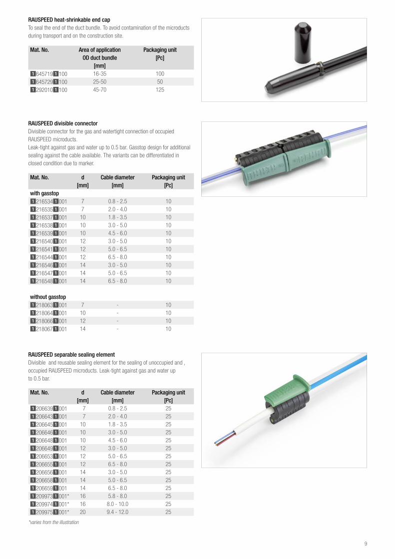
RAUSPEED separable sealing elementDivisible and reusable sealing element for the sealing of unoccupied and ‚ occupied RAUSPEED microducts. Leak-tight against gas and water up to 0.5 bar.
Mat No d Cable diameter Packaging unit [mm] [mm] [Pc]
12066391001 7 0.8 - 2.5 2512066431001 7 2.0 - 4.0 2512066451001 10 1.8 - 3.5 2512066461001 10 3.0 - 5.0 2512066481001 10 4.5 - 6.0 2512066491001 12 3.0 - 5.0 2512066531001 12 5.0 - 6.5 2512066551001 12 6.5 - 8.0 2512066561001 14 3.0 - 5.0 2512066581001 14 5.0 - 6.5 2512066591001 14 6.5 - 8.0 2512099731001* 16 5.8 - 8.0 2512099741001* 16 8.0 - 10.0 2512099751001* 20 9.4 - 12.0 25
*varies from the illustration
RAUSPEED divisible connectorDivisible connector for the gas and watertight connection of occupied RAUSPEED microducts.Leak-tight against gas and water up to 0.5 bar. Gasstop design for additional sealing against the cable available. The variants can be differentiated in closed condition due to marker.
Mat No d Cable diameter Packaging unit [mm] [mm] [Pc]
with gasstop12165341001 7 0.8 - 2.5 1012165351001 7 2.0 - 4.0 1012165371001 10 1.8 - 3.5 1012165381001 10 3.0 - 5.0 1012165391001 10 4.5 - 6.0 1012165401001 12 3.0 - 5.0 1012165411001 12 5.0 - 6.5 1012165441001 12 6.5 - 8.0 1012165461001 14 3.0 - 5.0 1012165471001 14 5.0 - 6.5 1012165481001 14 6.5 - 8.0 10
without gasstop12180631001 7 - 1012180641001 10 - 1012180661001 12 - 1012180671001 14 - 10
RAUSPEED heat-shrinkable end capTo seal the end of the duct bundle. To avoid contamination of the microducts during transport and on the construction site.
Mat No Area of application Packaging unit OD duct bundle [Pc]
[mm]16457191100 16-35 10016457291100 25-50 5012920101100 45-70 125
9

Mat No Dimensions Cable Packaging unit[mm] diameter [Pc]
12258721001 7 2.0 - 5.5 10011502241001 7 0.5 - 3.5 10012258921001 10 5.0 - 8.0 10011502251001 10 1.0 - 4.0 10011501851001 12 7.0 - 10.0 10011502261001 12 3.0 - 6.0 10011502271001 12 5.0 - 8.0 10011501931001 14 9.0 - 12.0 10011502281001 14 7.0 - 10.0 10011502291001 14 5.0 - 8.0 10011502341001 14 3.0 - 8.0 100
RAUSPEED closed sealing elementSecure and pressure-tight connection up to 0.5 bar of optical fibre cable to the microduct.
RAUSPEED branch supportFor secure pipe guidance at the branch. Retrospective installation possible. Can be used for RAUSPEED single ducts from 7-20 mm.Observe the min. bending radius of the single ducts.
Mat No Dimensions Packaging unit[Pc]
12391931001 25 25
RAUSPEED divisible flexible ductTo combine and protect RAUSPEED / cables e.g. in chambers. Subsequent installation possible. Good mechanical load-bearing capacity.UV-resistant.
Mat No Dimensions ID AD Packaging unit[mm] [mm] [mm] [Pc]
11006761001 20 19.2 25.3 5011006771001 23 23.4 30.8 5011006781001 37 31.0 41.4 2511006791001 45 42.7 54.0 25
10

RAUSPEED wall entryWall entry for the secure sealing of building connections when inserting RAUSPEED micro cable ducts through the house wall into the building.Gas and watertight up to a 4 m head of water. Variants for the connection of several micro cable ducts are available. Unused openings at the sealing head can be closed. As standard with integrated sealing mass at the sealing head to create the seal between the borehole and outside wall. Additional design with foam tube for the retrospective foaming along the length of the borehole in the case of unfavourable masonry conditions. The information below about the Tangit cartridges provided is to be noted for this purpose.Incl. grid for bending the micro cable duct inside the building whilst keeping to the min. radius.
Note:A two-component cartridge gun is required when using Tangit foam on the foamed design!
If a two-component cartridge gun is not available, an adapter can be used as an alternative: Adapter for standard cartridge gunMat. No. 11034031001
Mat No Dimensions Wall thickness Borehole dia- PackagingMKR [mm] [mm] meter [mm] unit [Pc]
Unfoamed design11500011001 7-12 up to 400 26-27 1
Foamed design11027701001 7-12 200-1,200 40 111027751001 12-14 200-1,200 40 111027761001 2 x 7 200-1,200 40 111037541001 3 x 10 200-1,200 62-65 1
RAUSPEED trenchless wall entryWall entry for application in trenchless constructions in the house connection area using the soil displacement process (impact mole).Assembly from the inside of the building. Gas and watertight up to 1 bar.Application for the connection of existing houses to avoid civil engineering works in the land area. Prevents subsequent subsidence or damage to growth.
Mat No Dimensions Wall thickness Borehole dia- PackagingMKR [mm] [mm] meter [mm] unit [Pc]
Unfoamed design11037071001 4 x 7 200-1,200 62-65 10
Other dimensions on request
Optional:Grid for bending the micro cable duct inside of the building: Mat. No. 11037371001
11
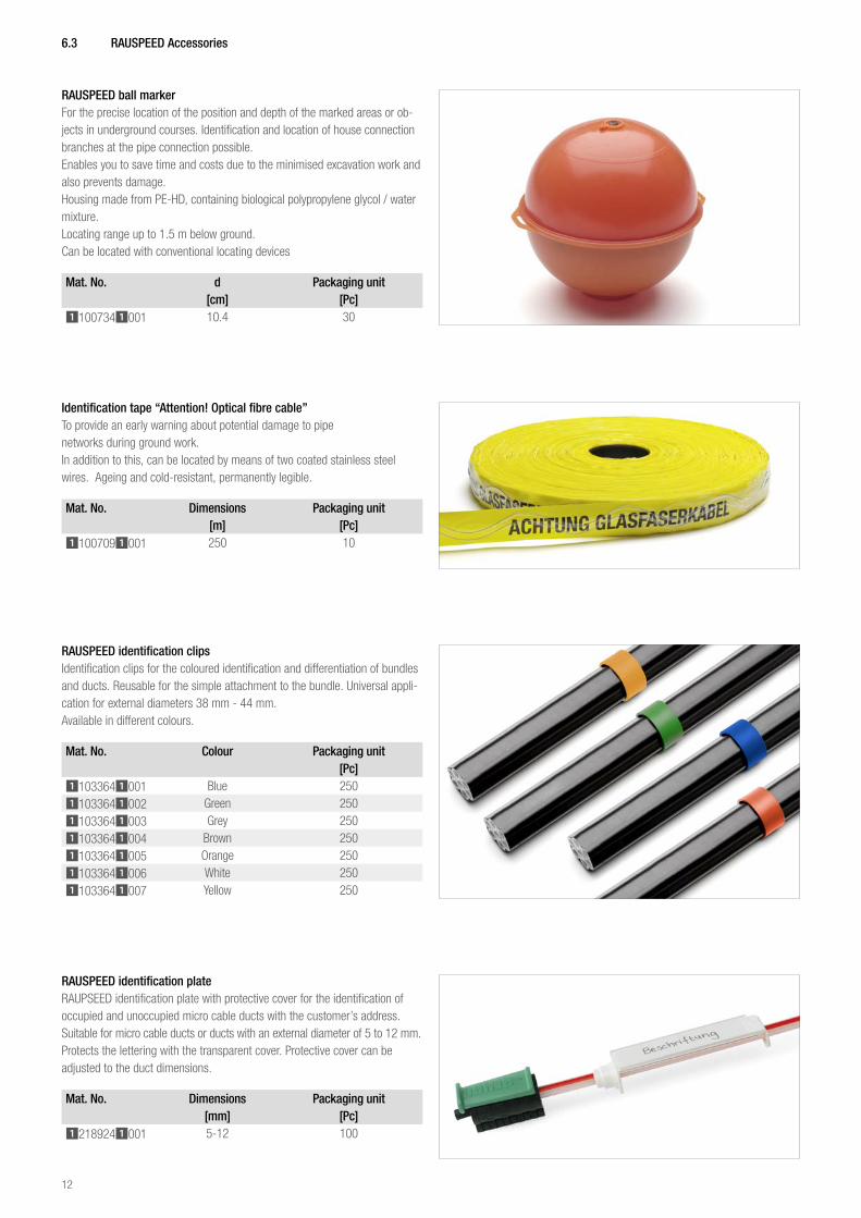
RAUSPEED identification clipsIdentification clips for the coloured identification and differentiation of bundles and ducts. Reusable for the simple attachment to the bundle. Universal appli-cation for external diameters 38 mm - 44 mm.Available in different colours.
Mat No Colour Packaging unit[Pc]
11033641001 Blue 25011033641002 Green 25011033641003 Grey 25011033641004 Brown 25011033641005 Orange 25011033641006 White 25011033641007 Yellow 250
6 3 RAUSPEED Accessories
RAUSPEED ball markerFor the precise location of the position and depth of the marked areas or ob-jects in underground courses. Identification and location of house connection branches at the pipe connection possible.Enables you to save time and costs due to the minimised excavation work and also prevents damage.Housing made from PE-HD, containing biological polypropylene glycol / water mixture.Locating range up to 1.5 m below ground.Can be located with conventional locating devices
Mat No d Packaging unit[cm] [Pc]
11007341001 10.4 30
Identification tape “Attention! Optical fibre cable”To provide an early warning about potential damage to pipe networks during ground work.In addition to this, can be located by means of two coated stainless steel wires. Ageing and cold-resistant, permanently legible.
Mat No Dimensions Packaging unit[m] [Pc]
11007091001 250 10
RAUSPEED identification plateRAUPSEED identification plate with protective cover for the identification of occupied and unoccupied micro cable ducts with the customer’s address.Suitable for micro cable ducts or ducts with an external diameter of 5 to 12 mm.Protects the lettering with the transparent cover. Protective cover can be adjusted to the duct dimensions.
Mat No Dimensions Packaging unit[mm] [Pc]
12189241001 5-12 100
12
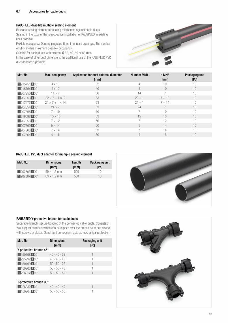
RAUSPEED divisible multiple sealing elementReusable sealing element for sealing microducts against cable ducts.Sealing in the case of the retrospective installation of RAUSPEED in existing lines possible.Flexible occupancy: Dummy plugs are fitted in unused openings. The number of MKR means maximum possible occupancy.Suitable for cable ducts with external Ø 32, 40, 50 or 63 mm.In the case of other duct dimensions the additional use of the RAUSPEED PVC duct adapter is possible.
Mat No Max occupancy Application for duct external diameter Number MKR d MKR Packaging unit[mm] [mm] [Pc]
12157511001 4 x 10 32 4 10 1012157541001 5 x 10 40 5 10 1012073501001 14 × 7 50 14 7 1012073531001 22 × 7 + 1 ×12 63 22 + 1 7 + 12 1012174771001 24 × 7 + 1 × 14 63 24 + 1 7 + 14 1012073541001 24 × 7 63 24 7 1012073561001 7 × 10 50 7 10 1012166971001 15 × 10 63 15 10 1012073581001 7 × 12 50 7 12 1012073601001 5 × 14 50 5 14 1012073631001 7 × 14 63 7 14 1012073641001 4 × 16 50 4 16 10
6 4 Accessories for cable ducts
RAUSPEED PVC duct adapter for multiple sealing element
Mat No Dimensions Length Packaging unit[mm] [mm] [Pc]
12073661001 50 × 1.8 mm 500 1012073671001 63 × 1.9 mm 500 10
RAUSPEED Y-protective branch for cable ductsSeparable branch, secure bonding of the connected cable ducts. Consists of two support channels which can be clipped over the branch point and closed with screws or clasps. Sand-tight component; acts as mechanical protection.
Mat No Dimensions Packaging unit[mm] [Pc]
Y-protective branch 45°11501981001 40 - 40 - 32 112259921001 40 - 40 - 40 111501991001 50 - 50 - 32 111502031001 50 - 50 - 40 112260121001 50 - 50 - 50 1
T-protective branch 90°12260321001 40 - 40 - 40 111502041001 50 - 50 - 50 1
13

Spare blade for shears 63
Mat No Packaging unit[Pc]
11315571001 1
RAUSPEED bundle shearsFor the clean, chip-free trimming of micro cable duct bundles up to 63 mm.One-handed operation possible due to the compact shape.Fold-out retaining collar provides additional retention for duct dimensions up to 50 mm.
RAUSPEED composite longitudinal cutting knifeFor opening the jacket at the end or in the middle of the bundle.
Mat No Packaging unit[Pc]
11315581001 1
Mat No Packaging unit[Pc]
11502351001 1
RAUSPEED composite duct cutterFor opening the jacket of the bundle.
Mat No Packaging unit[Pc]
11502361001 1
6 5 RAUSPEED Tools
14

RAUSPEED duct cutter for occupied ducts
RAUSPEED cutter for unoccupied ducts
Mat No Packaging unit[Pc]
11502381001 1
Mat No Duct dimensions Packaging unit[mm] [Pc]
11502371001 5-12 111502491001 14-20 1
Spare blade for RAUSPEED duct cutter for unoccupied ducts
Mat No Duct dimensions Packaging unit[mm] [Pc]
11009791001 5-12 511009781001 14-20 1
RAUCUT IPrecision tool for opening and exposing the LWL fibres of cut or uncut bundle wires.
Mat No Packaging unit[Pc]
12694661050 1
15

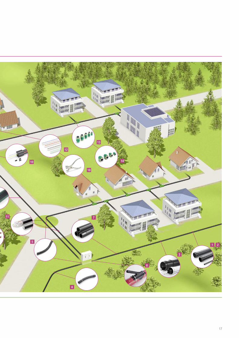
REHAU TELECOMMUNICATIONS PRODUCTSSYSTEM SOLUTIONS FOR LOCAL AREA AND WIDE AREA NETWORKS
Backbone1 PVC cable duct 2 PE cable duct3 PP cable duct4 PVC cable duct bend5 Flexible bend6 Swept T-branch 7 RAUDUCT EVMR multiple
subducting pipes
Distribution network8 RAUDUCT
multiple subducting pipes9 REHAU plug connectors10 RAUSPEED multiple sealing element11 RAUSPEED duct bundles12 RAUSPEED microducts13 RAUSPEED plug connector14 RAUSPEED end caps15 RAUSPEED sealing elements16 RAUSPEED wall grommet17 RAUSPEED pipe shear18 RAUSPEED pipe cutter
4
6
1
12
13
13 16
9
11
5
8
3
15
14
17
2
7
14
18
10
12-08-20_Doppelseite_Kabelschutz.indd 1-2 08.10.2012 11:37:41
16
REHAU TELECOMMUNICATIONS PRODUCTSSYSTEM SOLUTIONS FOR LOCAL AREA AND WIDE AREA NETWORKS
Backbone1 PVC cable duct 2 PE cable duct3 PP cable duct4 PVC cable duct bend5 Flexible bend6 Swept T-branch 7 RAUDUCT EVMR multiple
subducting pipes
Distribution network8 RAUDUCT
multiple subducting pipes9 REHAU plug connectors
10 RAUSPEED multiple sealing element11 RAUSPEED duct bundles12 RAUSPEED microducts13 RAUSPEED plug connector14 RAUSPEED end caps15 RAUSPEED sealing elements16 RAUSPEED wall grommet17 RAUSPEED pipe shear18 RAUSPEED pipe cutter
4
6
1
12
13
13 16
9
11
5
8
3
15
14
17
2
7
14
18
10
12-08-20_Doppelseite_Kabelschutz.indd 1-2 08.10.2012 11:37:41
17

7 Planning and installation
General informationPE-HD microducts are to be installed by suitable specialists under qualified supervision. During this installation work, it is imperative to note the accident prevention guidelines of the trade associations or occupational safety inspec-tions, the road traffic act, the VOB General Technical Contractual conditions for construction services, Part C as well as all regional legislation and provisions.
TransportThe duct sections are to be transported using suitable vehicles and loaded and unloaded by experienced persons.To avoid contamination, the microducts are sealed with RAUSPEED transport caps in the plant.During transport and storage, point loading as well as contact with sharp objects is to be avoided.
StorageGoods on drums are to be stored in such a way that the load is borne exclusi-vely by the drum flange. All duct sections are to be stored in such a way that they cannot be contaminated. No permanent deformation or damage to the ducts must occur as a result of storage. This is to be ensured in particular if drums are stored on uneven ground.During storage a stone-free base without contact with the ground is to be ensured. If necessary, a suitable base is to be created using additional mea-sures (e.g. wooden boards). The RAUSPEED microducts made from PE-HD are UV-stabilised and can be stored outside in Central Europe for up to a year. Direct sunlight as well as heating the ducts to above 35 °C should however be avoided, as coiled microducts can become oval due to the force of their own weight.
Temperature rangeThere are no temperature restrictions for the transport of PE-HD cable ducts. However, it is to be noted that, at temperatures > 50 °C, small mechanical loads can already lead to deformation and that at temperatures < -15 °C the duct material must not be subjected to any impact stress.The installation of RAUSPEED microducts and the blowing or feeding in of cables can take place at temperatures from -15 °C to 50 °C.
Unwinding goods on drumsThe ducts are to be unwound so that they are straight and must not be kinked. Pulling them off from the side in a spiral is not permitted.When unwinding the ducts from the drums, it is to be noted that ends of the duct can spring out.As particularly in the case of large ducts considerable forces are released, the appropriate care is to be taken.In addition to this, when unwinding the duct, it is to be noted that the flexibility of the ducts is influenced by the ambient temperature. At temperatures close to freezing, it is recommended that the ducts that are still wound up are war-med to improve handling. This can be done e.g. with warm air (max. 80 °C). It is also recommendable to store the ducts temporarily in a heated hall or under a heated tarpaulin for a period of several hours. When creating infill lengths, the temperature-related length fluctuation of the ducts is to be noted.If the temperature of the duct wall rises or falls by 1 Kelvin (1 K = 1 °C) a duct made from PE-HD lengthens or shortens by 0.2 mm per each metre of length. At a temperature difference of Δ-5 Kelvin, the duct therefore shortens by 1 cm. Primarily in high summer, in order to avoid stresses within the duct system, the section of duct must already be lying in the trench for some time prior to back-filling, so that an alignment takes place between the duct and the ground.
Blowing in of RAUSPEED microductsRAUSPEED microducts can be blown into cable ducts using conventional blowing in devices.The manufacturer‘s instructions are to be observed when doing this. Before microducts can be blown into cable ducts, it is necessary to apply com-pressedair in order to increase the rigidity. This stops the microducts lying on top of one another and twisting during blowing in, as a result of which, the blowing in length would be reduced. Furthermore, the ovality of the duct is decreased by the supporting air. To do this, the microducts - whilst still on the cable drum - are subjected to compressed air of approx. 10 bar on the inside of the duct and remain in this condition on the cable drum for approx. one hour. In order to be able to apply the pressure, the end of the microduct is sealed with a protective cap made from brass.
Feeding in RAUSPEED microductsFor maximum occupancy of the existing ducts, RAUSPEED microducts can be fed in from the microduct bundle. The individual microducts are fed in with the help of a draw cord or pulling head.The jacket composite is slit prior to insertion of the duct with the help of a cutting device. The achievable pull in length is restricted by the following permitted tensile forces of the microducts.
Microduct Tensile force 7 × 0.75 80 N 7 × 1.5 200 N
10 × 1 150 N10 × 2 300 N12 × 1 200 N12 × 2 300 N14 × 2 350 N16 × 2 350 N20 x 2 350 N
Direct installation into the groundDirect installation into the ground in sand 0/2 is generally possible.When doing this, it is to be ensured that coarse soil components cannot spread as far as the microducts. Furthermore, the risk of the ducts being chewed by rodents is to be considered.Microducts with thick-walled dimensions (wall thickness > 1.5 mm) can be directly installed into the ground, those with lower wall thicknesses must additionally be inserted into a cable duct made from PE, PP or PVC.
18

Installation of RAUSPEED duct bundles
GeneralDuring installation, the microducts to be installed must not be pulled across sharp edges. The cable ducts must not be kinked. Impact loads on the cable ducts are to be avoided.
Duct trenchesDuct trenches are to be created in such a way that all duct parts can be laid at a suitable depth, taking into account structural requirements.Only a stone-free, compactable material must be used for the trench base and the duct bedding. The trench base is to be compacted with a light compacting device prior to the installation process. Even compacting is to be ensured when doing this.Machine compacting devices must only be used with a top fill of more than 30 cm.
The trench base should be flat. Waviness in the base, e.g. that can be caused by a digger, is to be evened out.
In rocky or sandy subsoil, the trench base is to be excavated at least 0.15 m deeper and the excavated material replaced with a stone-free layer (sand 0-6 with largest grain size ø 6 mm).
Incorrect installation!
Surface
MKR-bundle
Flattened and compacted trench bottom
Compacted, stone-free base
Sand top fill approx. 10 cm
Trench base levelled and compacted with a sand bed
Unworked trench base after soil excavation
Surface
approx. 10-15 cm
Surface
Unworked trench base after soil excavation
If the waviness in the trench base is not evened out, this is transferred to the microduct bundle, which results in a considerable reduction of the blowing in length.In the case of a non-load-bearing and heavily water-saturated trench base, as well as the risk of the backfilling material to be applied being washed out due to fluctuating groundwater levels, stabilisation is to be ensured through suitable measures.The support and bedding in of the ducts and fittings are to be carried out according to DIN EN 1610.On slopes, suitable precautions must be taken to ensure that the duct bedding is not washed away and that water does not wash under the duct. On inclines and slopes, the duct is also to be secured against slipping, e.g. with a bolt.In the case of changing soil layers and the associated changes in load-bearing capability of the trench base, a sufficiently long fine gravel or sand filling is to be put in place at the transition points.The duct connecting points are to be kept free for the pressure test if possible.
CompactingIn order to avoid damage to the ducts, the filler material is generally to be compacted by hand in the area of the duct zone. The compacted layer of filler material over the top duct layer should be at least 10 cm.
Ploughing in and cutting inDue their flexibility and the option of delivery on drums, microduct bundles are particular suitable for ploughing/cutting in directly into the ground.Above a top fill height of > 0.9 m, moving loads up to SLW 60 are possible without problems based on experience.In order to plough in the microducts, these are fastened to a so-called cable plough, which is moved forward through the ground with the help of a digger. This process can however only be used if there is no fixed road surface and no obstacles will obstruct ploughing in.
When removing the microduct bundle from the spool, linear installation under tension is to be ensured in particular.(In addition to these installation guidelines, any other guidelines of the client for the ploughing in of microduct bundles, ducts or cables are to be observed).High tensile forces occur with these methods.
Surface
Installation direction
Trench base
19

Maximum permitted tensile forces of the bundles must be observed here:
Microduct bundle Tensile force (20 °C) / N2 x 7 x 1.5 3506 x 7 x 1.5 1,0508 x 7 x 1.5 1,40010 x 7 x 1.5 1,80012 x 7 x 1.5 2,10014 x 7 x 1.5 2,50018 x 7 x 1.5 3,200
22 x 7 x 1.5 + 1 x 12 x 2.0 4,20024 x 7 x 1.5 + 1 x 14 x 2.0 4,600
24 x 7 x 1.5 4,3006 x 10 x 2.0 1,60012 x 10 x 2.0 3,2005 x 12 x 2.0 6507 x 12 x 2.0 9002 x 12 x 2.0 5003 x 12 x 2.0 8004 x 12 x 2.0 1,0005 x 12 x 2,0 1,3507 x 12 x 2.0 1,850
8 x 12 x 2.0 + 1 x 20 x 2.0 2,4502 x 14 x 2.0 6003 x 14 x 2.0 9004 x 14 x 2.0 1,2505 x 14 x 2.0 1,5507 x 14 x 2.0 2,2002 x 16 x 2.0 6003 x 16 x 2.0 9004 x 16 x 2.0 1,2506 x 16 x 2.0 1,8502 x 20 x 2.0 6003 x 20 x 2.0 9004 x 20 x 2.0 1,2505 x 20 x 2.0 1,5506 x 20 x 2.0 1,850
In open trenchesThe microduct bundles must not be unwound by rolling the drum on the ground.There is a risk that the microducts will be squashed by doing this. A drum trailer or a laying carriage is therefore always to be used.
When removing the microduct bundle from the spool, linear installation under tension is to be ensured in particular. Unwinding the microduct bundle over the flange (in the direction of the spool axis) is not permitted (risk of spiral formation).
Bending radiiThe smallest permitted bending radius of the microduct bundle depends on the installation temperature and must not fall below the values given in the table. The bigger the bending radii, the bigger the blowing in values are later on.
Installation temperature Smallest permitted bending radius of the bundle20 °C > 1.0 m10 °C > 2.0 m 0 °C > 2.5 m
Recommendation: Avoid bundle bending radii < 2 5 mWhen installing RAUSPEED microducts a minimum bending radius of 10 times OD is generally to be observed. So as not to impair the blowing in length too much, however, a minimum bending radius of 200 mm is recom-mended.The use of RAUSPEED branching aids guarantees safe pipe bending.
Opening the bundle and creating a branchIt is necessary to open the bundle jacket to create a branch at the height of the building to be connected. It is recommended to use a suitable tool, e.g. a RAUSPEED composite longitudinal blade, to do this.If an end piece is available, the composite longitudinal blade is posi-tioned at the edge of the black jacket and this is opened as far as required.Once the jacket is open, a microduct can be pulled out of the bundle.If there is not an end piece, but a continuous microduct bundle, a suitable tool, e.g. a RAUSPEED composite longitudinal cutter or a RAUSPEED compo-site pipe cutter is used to cut into the jacket. When cutting, take care not to damage the microducts inside and to only cut into the cavity between the 2 microducts.Once the bundle has been opened 50 - 70 cm wide and the single micro-ducts are therefore accessible, the microduct from which a branch should be created is separated with a suitable RAUSPEED duct cutter and removed from the bundle. If the glass fibres are provided only once instead of twice, one end of the micro cable duct that has been cut through remains unoccupied and must be sealed immediately with an end cap. The other end of the separated microduct is connected to the microduct that leads to the subscriber terminal with the help of a plug connector.
The whole bundle is to be trimmed with suitable duct shears. A chip-produ-cing tool, e.g. a saw, must not be used for cutting, as any chips on the interior edge of the ducts as well as dented ducts could hinder the blowing in process. All duct ends are to be sealed again once cut to length with transport or end caps to prevent the ducts becoming dirty and water ingress.
Surface
Installation direction
Open trench
Pull direction
Trench base
20

Connecting microductsPlug connectors are used for the secure and pressure-tight connection of RAUSPEED microducts of the same diameter. Reducing fittings are used for the connection of two microducts with different diameters.The microducts are to be separated with a RAUSPEED duct cutter to do this. A straight cut at right angles to the pipe axis is to be ensured without fail. It is not necessary to chamfer the microducts prior to inserting them into the fittings.When inserting the microducts into the plug connector the clamping teeth inside are pushed outward and lie against the micro cable duct. When tensile force is applied, the clamping teeth get caught and therefore strengthen the connection. It is only possible to break the connection once the magenta-co-loured circlip can be removed by hand or with a suitable tool and the release ring can therefore be pressed down, in order to retract the teeth.In the duct bundle microducts with the same coloured stripes are connected to each other in each case. When connecting two duct bundles the micro-ducts should be connected offset to each other in order to avoid several connectors lying on top of one another.To protect the connection points against mechanical damage it is recommen-ded to use a divisible RAUSPEED flexible duct.
21

Creating house connectionsTo lead microducts into the building the branched microduct is fed through the house wall so that it is secure and leaktight using the RAUSPEED wall entry. Please see the associated assembly instructions regarding the installation of the wall entry.
Blowing in of fibre optic cablesFibre optic cables can be blown into RAUSPEED microducts using conventi-onal blowing in devices. The manufacturer‘s instructions are to be observed when doing this.In order to ensure a smooth blowing in process, the fibre optic cables to be blown in must be fitted with a cable guide head.The blowing in process then takes place in a similar way to the blowing in of microducts into cable ducts. To improve the blowing in behaviour the microducts have the special REHAU RTR internal grooving, also known as trapezoidal grooving.This grooving prevents turbulent currents during the blowing in process and therefore increases the blowing in length.
Recommended cable diameter for blowing in RAUSPEED single ducts
Dimensions ID Cable diameter* Number of fibres* 7 x 0.75 5,5 1.8 - 4.0 2 - 24 7 x 1.5 4 1.0 - 2.5 2 - 1210 x 1.0 8 2.5 - 6.5 12 - 7210 x 2.0 6 1.8 - 4.5 2 - 4812 x 2.0 8 2.5 - 6.5 12 - 7214 x 2.0 10 3.0 - 8.5 12 - 14416 x 2.0 12 6.5 - 10.4 72 - 19420 x 2.0 16 10.0 - 14.0 144 - 288
*Values depend on the respective cable manufacturer
Sealing elementIn the building, the optical fibre bundle is pulled out of the microduct and fedinto a house connection box. When doing this, it is important that the opticalfibre cable is sealed to the microduct prior to introduction into the house con-nectionbox, in order to prevent either gas or water being able to infiltrate intothe building or seep out of the building. The sealing of the mini/micro cable iscarried out with closed or divisible sealing elements.
Closed sealing elementThe closed sealing element works in a similar way to a plug connector. Themicroduct is pushed into the component and retained there.A sealing ring makes the duct gas and water-tight.The sealing ring is compressed by turning the nuts.In contrast to the divisible sealing element, the closed sealing element canonly be fitted by pulling one end of the microduct through the component. Ifthis microduct is already occupied, a divisible sealing element can be used.
Divisible sealing elementThe divisible sealing element consists of a housing, a clamping rail and a rubber seal. The latter can be cut open if the microduct is already installed and fitted retrospectively onto the microduct of the relevant dimensions and occupied with optical fibre cable. The small opening here is on the side of the optical fibre cable.The housing is then fitted to the seal and pushed against the sealing lips on closure. The clamping rail is used for fixing and sealing.The divisible sealing element is gas and water-tight up to 0.5 bar.
22

Divisible multiple sealing elementIn the case of fitting microducts retrospectively into existing sections or the introduction of complete bundles into buildings, cable branches or chambers, microducts can be sealed against cable ducts with a separable multiple sealing element.A duct adaptor is applied around the microduct bundle after removal of the outer bundle jacket and exposing the microducts. The microducts are inserted into the openings of rubber seals in the respective amount matching that of the microducts and the seal is pushed all the way to the end of the duct adapter. Apply adhesive tape around a large area of the rubber seal and duct adapters in order to seal them. The housing halves are applied around the duct adapter and the seal and fixed in place with clamping rails.If the full number of microducts is not used, the openings that are not used can be fitted with plugs.
23

REHAU SALES OFFICES AT: Linz, +43 732 3816100, [email protected] Wien, +43 2236 24684, [email protected] Graz, +43 361 403049, [email protected] BA: Sarajevo, +387 33 475500, [email protected] BE: Bruxelles, +32 16 399911, [email protected] BG: Sofia, +359 2 8920471, [email protected] BY: Minsk, +375 17 2450209, [email protected] CH: Bern, +41 31 720120, [email protected] Vevey, +41 21 9482636, [email protected] Zuerich, +41 44 8397979, [email protected] CZ: Praha, +420 272 190111, [email protected] DE: Berlin, +49 30 667660, [email protected] Bielefeld, +49 521 208400, [email protected] Bochum, +49 234 689030, [email protected] Frankfurt, +49 6074 40900, [email protected] Hamburg, +49 40 733402100, [email protected] Hannover, +49 5136 891181, [email protected] Leipzig, +49 34292 820, [email protected] München, +49 8102 860, [email protected] Nürnberg, +49 9131 934080, [email protected] Stuttgart, +49 7159 16010, [email protected] Ingolstadt, +49 841 142626200, [email protected] DK: Kobenhavn, +45 46 773700, [email protected] EE: Tallinn, +372 6025850, [email protected] ES: Barcelona, +34 93 6353500, [email protected] Bilbao, +34 94 4538636, [email protected] Madrid, +34 91 6839425, [email protected] FI: Helsinki, +358 9 87709900, [email protected] FR: Lyon, +33 4 72026300, [email protected] Metz, +33 6 8500, [email protected] Paris, +33 1 34836450, [email protected] GB: Glasgow, +44 1698 503700, [email protected] Manchester, +44 161 7777400, [email protected] Slough, +44 1753 588500, [email protected] Ross on Wye, +44 1989 762643, [email protected] London, +44 207 3078590, [email protected] GR: Athens, +30 21 06682500, [email protected] Thessaloniki, +30 2310 633301, [email protected] HR: Zagreb, +385 1 3444711, [email protected] HU: Budapest, +36 23 530700, [email protected] IE: Dublin, +353 1 8165020, [email protected] IT: Pesaro, +39 0721 200611, [email protected] Roma, +39 06 90061311, [email protected] Treviso, +39 0422 726511, [email protected] LT: Vilnius, +370 5 2461400, [email protected] LV: Riga, +371 6 7609080, [email protected] MK: Skopje, +389 2 2402, [email protected] NL: Nijkerk, +31 33 2479911, [email protected] NO: Oslo, +47 2 2514150, [email protected] PL: Katowice, +48 32 7755100, [email protected] Warszawa, +48 22 2056300, [email protected] PT: Lisboa, +351 21 8987050, [email protected] Oporto, +351 22 94464, [email protected] RO: Bacau, +40 234 512066, [email protected] Bucuresti, +40 21 2665180, [email protected] Cluj Napoca, +40 264 415211, [email protected] RS: Beograd, +381 11 3770301, [email protected] RU: Chabarowsk, +7 4212 411218, [email protected] Jekaterinburg, +7 343 2535305, [email protected] Krasnodar, +7 861 2103636, [email protected] Nishnij Nowgorod, +7 831 4678078, [email protected] Nowosibirsk, +7 3832 000353, [email protected] Rostow am Don, +7 8632 978444, [email protected] Samara, +7 8462 698058, [email protected] St Petersburg, +7 812 3266207, [email protected] Woronesch, +7 4732 611858, [email protected] SE: Örebro, +46 19 206400, [email protected] SK: Bratislava, +421 2 68209110, [email protected] UA: Dnepropetrowsk, +380 56 3705028, [email protected] Kiev, +380 44 4677710, [email protected] Odessa, +380 48 7800708, [email protected] Lviv, +380 32 2244810, [email protected] If there is no sales office in your country, +49 9131 925888, [email protected]
This document is protected by copyright. All rights based on this are reserved. No part of this publication may be translated, reproduced or transmitted in any form or by any similar means, electronic or mechanical, photocopying, recording or otherwise, or stored in a data retrieval system.
Our verbal and written advice relating to technical applications is based on experience and is to the best of our knowledge correct but is given without obligation. The use of REHAU products in conditions that are beyond our control or for applications other than those specified releases us from any obligation in regard to claims made in respect of the products. We recommend that the suitability of any REHAU product for the intended application should be checked. Utilization and processing of our products are beyond our control and are therefore exclusively your responsibility. In the event that a liability is nevertheless considered, any compensation will be limited to the value of the goods supplied by us and used by you. Our warranty assumes consistent quality of our products in accordance with our specification and in accordance with our general conditions of sale.
www.rehau.com 374680 EN 10.2014


