Ray Tracing Deformable Scenes Using Dynamic Bounding Volume Hierarchies INGO WALD, SOLOMON BOULOS, and PETER SHIRLEY University of Utah The most significant deficiency of most of today’s interactive ray tracers is that they are restricted to static walkthroughs. This restriction is due to the static nature of the acceleration structures used. While the best reported frame rates for static geometric models have been achieved using carefully constructed kd-trees, this article shows that bounding volume hierarchies (BVHs) can be used to efficiently ray trace large static models. More importantly, the BVH can be used to ray trace deformable models (sets of triangles whose positions change over time) with little loss of performance. A variety of efficiency techniques are used to achieve this performance, but three algorithmic changes to the typical BVH algorithm are mainly responsible. First, the BVH is built using a variant of the surface area heuristic conventionally used to build kd-trees. Second, the topology of the BVH is not changed over time so that only the bounding volumes need to be refit from frame-to-frame. Third, and most importantly, packets of rays are traced together through the BVH using a novel integrated packet-frustum traversal scheme. This traversal scheme elegantly combines the advantages of both packet traversal and frustum traversal and allows for rapid hierarchy descent for packets that hit bounding volumes as well as rapid exits for packets that miss. A BVH-based ray tracing system using these techniques is shown to achieve performance for deformable models comparable to that previously available only for static models. Categories and Subject Descriptors: I.3.7 [Computer Graphics]: Three-Dimensional Graphics and Realism—Raytracing; I.3.3 [Computer Graphics]: Picture/Image Generation—Display algorithms General Terms: Algorithms, Performance Additional Key Words and Phrases: ACM Reference Format: Wald, I., Boulos, S., and Shirley, P. 2007. Ray tracing deformable scenes using dynamic bounding volume hierarchies. ACM Trans. Graph. 26, 1, Article 6 (January 2007), 18 pages. DOI = 10.1145/1186644.1186650 http://doi.acm.org/ 10.1145/1186644.1186650 1. INTRODUCTION Recent trends in computer architecture and model complexity, along with a desire for improved visual realism, have spurred researchers to consider ray tracing as an alternative to Z-buffering, and ray trac- ing has since been demonstrated to be a viable method for a wide class of interactive applications [Muuss 1995; Parker et al. 1999; Wald 2004; Reshetov et al. 2005]. Until recently, these demon- strations have largely been restricted to static scenes; ray tracing dynamic scenes has not been able to yield such high frame rates. The reason ray tracing is problematic for dynamic scenes is that fast ray tracers use precomputed spatial search structures to achieve interactive frame rates. For most data structures, rebuilding these for each frame is too expensive except for relatively small models [Wald et al. 2003]. Ray tracing’s historical failure to deal with dynamic scenes is a major limitation because these scenes are important for a large class of applications such as games and simulation [Mark and Fussell 2005]. Because of their importance, several concurrent approaches for ray tracing dynamic scenes are currently being pur- I. Wald was supported by the State of Utah Center of Excellence Program and the US Department of Energy through the Center for the Simulation of Accidental Fires and Explosions under Grant W-7405-ENG-48. P. Shirley was supported by the National Science Foundation Grant 03-06141 and the Utah Center of Excellence Program. S. Boulos was supported by the Barry M. Goldwater Scholarship. Authors’ addresses: University of Utah, Salt Lake City, UT 84112; email: [email protected]; {boulos, shirley}@cs.utah.edu. Permission to make digital or hard copies of part or all of this work for personal or classroom use is granted without fee provided that copies are not made or distributed for profit or direct commercial advantage and that copies show this notice on the first page or initial screen of a display along with the full citation. Copyrights for components of this work owned by others than ACM must be honored. Abstracting with credit is permitted. To copy otherwise, to republish, to post on servers, to redistribute to lists, or to use any component of this work in other works requires prior specific permission and/or a fee. Permissions may be requested from Publications Dept., ACM, Inc., 2 Penn Plaza, Suite 701, New York, NY 10121-0701 USA, fax +1 (212) 869-0481, or [email protected]. c 2007 ACM 0730-0301/2007/01-ART6 $5.00 DOI 10.1145/1186644.1186650 http://doi.acm.org/ 10.1145/1186644.1186650 sued, for example Wald et al. [2006], Lauterbach et al. [2006], Stoll et al. [2006], G ¨ unther et al. [2006], and Carr et al. [2006]. In this article, we use a bounding volume hierarchy (BVH) [Rubin and Whitted 1980] to interactively ray trace a particular type of dy- namic scene, deformable scenes. A deformable scene is one whose triangles move, but no triangles are split, created, or destroyed over time. An example of such a scene is shown in Figure 1, where two meshes deform and change position within an animated polygo- nal environment. The entire scene is ray traced with a single BVH whose topology is constant for the whole animation. This approach was motivated by the successful use of constant topology BVHs for collision detection between deformable objects [van den Bergen 1997; Schmidl et al. 2004]. In contrast to spatial subdivision struc- tures such as the kd-tree, the BVH subdivides the object hierarchy, and a given object hierarchy is more robust over time than a given subdivision of space. As a result, a BVH can be quickly updated between frames, thus avoiding a complete per-frame rebuilding phase [Larsson and Akenine-M¨ oller 2003]. However, a barrier to exploiting the BVH’s advantages for dynamic scenes is that their ACM Transactions on Graphics, Vol. 26, No. 1, Article 6, Publication date: January 2007.
Transcript
Ray Tracing Deformable Scenes Using Dynamic BoundingVolume Hierarchies
INGO WALD, SOLOMON BOULOS, and PETER SHIRLEY
University of Utah
The most significant deficiency of most of today’s interactive ray tracers is that they are restricted to static walkthroughs. This restriction is due to the staticnature of the acceleration structures used. While the best reported frame rates for static geometric models have been achieved using carefully constructedkd-trees, this article shows that bounding volume hierarchies (BVHs) can be used to efficiently ray trace large static models.
More importantly, the BVH can be used to ray trace deformable models (sets of triangles whose positions change over time) with little loss of performance.A variety of efficiency techniques are used to achieve this performance, but three algorithmic changes to the typical BVH algorithm are mainly responsible.First, the BVH is built using a variant of the surface area heuristic conventionally used to build kd-trees. Second, the topology of the BVH is not changed overtime so that only the bounding volumes need to be refit from frame-to-frame. Third, and most importantly, packets of rays are traced together through theBVH using a novel integrated packet-frustum traversal scheme. This traversal scheme elegantly combines the advantages of both packet traversal and frustumtraversal and allows for rapid hierarchy descent for packets that hit bounding volumes as well as rapid exits for packets that miss. A BVH-based ray tracingsystem using these techniques is shown to achieve performance for deformable models comparable to that previously available only for static models.
Categories and Subject Descriptors: I.3.7 [Computer Graphics]: Three-Dimensional Graphics and Realism—Raytracing; I.3.3 [Computer Graphics]:Picture/Image Generation—Display algorithms
General Terms: Algorithms, Performance
Additional Key Words and Phrases:
ACM Reference Format:
Wald, I., Boulos, S., and Shirley, P. 2007. Ray tracing deformable scenes using dynamic bounding volume hierarchies. ACM Trans. Graph. 26, 1, Article 6(January 2007), 18 pages. DOI = 10.1145/1186644.1186650 http://doi.acm.org/ 10.1145/1186644.1186650
1. INTRODUCTION
Recent trends in computer architecture and model complexity, alongwith a desire for improved visual realism, have spurred researchersto consider ray tracing as an alternative to Z-buffering, and ray trac-ing has since been demonstrated to be a viable method for a wideclass of interactive applications [Muuss 1995; Parker et al. 1999;Wald 2004; Reshetov et al. 2005]. Until recently, these demon-strations have largely been restricted to static scenes; ray tracingdynamic scenes has not been able to yield such high frame rates.
The reason ray tracing is problematic for dynamic scenes is thatfast ray tracers use precomputed spatial search structures to achieveinteractive frame rates. For most data structures, rebuilding these foreach frame is too expensive except for relatively small models [Waldet al. 2003]. Ray tracing’s historical failure to deal with dynamicscenes is a major limitation because these scenes are important fora large class of applications such as games and simulation [Markand Fussell 2005]. Because of their importance, several concurrentapproaches for ray tracing dynamic scenes are currently being pur-
sued, for example Wald et al. [2006], Lauterbach et al. [2006], Stollet al. [2006], Gunther et al. [2006], and Carr et al. [2006].
In this article, we use a bounding volume hierarchy (BVH) [Rubinand Whitted 1980] to interactively ray trace a particular type of dy-namic scene, deformable scenes. A deformable scene is one whosetriangles move, but no triangles are split, created, or destroyed overtime. An example of such a scene is shown in Figure 1, where twomeshes deform and change position within an animated polygo-nal environment. The entire scene is ray traced with a single BVHwhose topology is constant for the whole animation. This approachwas motivated by the successful use of constant topology BVHsfor collision detection between deformable objects [van den Bergen1997; Schmidl et al. 2004]. In contrast to spatial subdivision struc-tures such as the kd-tree, the BVH subdivides the object hierarchy,and a given object hierarchy is more robust over time than a givensubdivision of space. As a result, a BVH can be quickly updatedbetween frames, thus avoiding a complete per-frame rebuildingphase [Larsson and Akenine-Moller 2003]. However, a barrier toexploiting the BVH’s advantages for dynamic scenes is that their
ACM Transactions on Graphics, Vol. 26, No. 1, Article 6, Publication date: January 2007.
2 • I. Wald et al.
Fig. 1. Screenshots from an animated 180,000 triangle scene with moving dragonfly, fairy, and plants. At 1024 × 1024 pixels the animated scene is ray tracedat roughly 3.7 frames-per-second on a dual 2.6 GHz Opteron desktop PC including shadows and texturing.
Box
2 tris2 tris
Box Box
Fig. 2. Different BVHs for 4 triangles. The siblings are allowed to spatially overlap (unlike spatial subdivision). Other possibilities include splitting to size 1and 3 triangle list and recursively splitting lists of 2 or 3 triangles.
performance on static scenes has lagged far behind that achievedusing kd-trees [Wald 2004; Reshetov et al. 2005].
In this article, we demonstrate how BVHs can be used for fastray tracing of static models by using many of the same techniquesdeveloped for kd-trees including careful tree construction, SIMDprogramming, and the use of ray packets. In addition, we proposea novel traversal algorithm that benefits from ray packets which aremuch larger than the 4-ray packets commonly used (e.g., Wald et al.[2001] and Lauterbach et al. [2006]). The combination of thesetechniques allows a BVH to be competitive with a kd-tree evenwhere kd-trees perform at their best. By using a constant topologyBVH that is only refit for each frame, we can naturally extend oursystem to handle dynamic scenes. We empirically show—for at leasta wide class of dynamic scenes—that the rendering performance ofusing a constant topology is close to the optimal case of a BVH builtspecifically for that frame. Our approach does not require knowledgeof all frames of an animation so it should be applicable to modelsdriven by physics or user interaction.
2. BACKGROUND
Ray tracing was used for rendering at least as early as the classicwork by Appel [1968], but was introduced in its modern form byWhitted [1980]. To speed up intersection, hand-constructed bound-ing volume hierarchies (BVHs) [Clark 1976] were the first spa-tial efficiency structure used for ray tracing [Rubin and Whitted1980; Whitted 1980]. While a BVH partitions objects, variousschemes for partitioning space soon became more popular for raytracing [Cleary et al. 1983; Glassner 1984; Kaplan 1985; Jansen1986; Arvo and Kirk 1989]. Kirk and Arvo [1988] speculated thatthe best efficiency scheme varied with object characteristics andadvocated a heterogeneous software architecture. The first mod-ern, systematic investigation of the various efficiency schemes wasconducted by Havran [2001] in his dissertation. He concluded that
kd-trees [Bentley 1975] were probably the best, and BVHs were byfar the worst data structures for ray tracing.
Interactive ray tracing. In the last decade a number of interactiveray tracing systems have been developed on a variety of architec-tures. Wald [2004] used kd-trees to achieve interactivity on bothsingle PCs and clusters of PCs. His implementation was released aspart of the OpenRT system which we use as a comparison baselinein this article. Interactive ray tracing has also been demonstratedon a variety of platforms including supercomputers [Parker 2002],FPGAs [Schmittler et al. 2002; Woop et al. 2005], GPUs [Purcellet al. 2002; Foley and Sugerman 2005; Carr et al. 2006], and theCell [Minor et al. 2005].
Bounding volume hierarchies. BVHs are trees that store a closedbounding volume at each node. In addition, each internal node hasreferences to child nodes, and each leaf node also stores a list of ge-ometric primitives. The bounding volume is guaranteed to enclosethe bounding volumes of all its descendants. Each geometric prim-itive is in exactly one leaf, while each spatial location can be inan arbitrary number of leaves. A variety of shapes have been usedfor the bounding volumes [Weghorst et al. 1984], with axis-alignedboxes a common choice. An example of different BVHs for a smallmodel are shown in Figure 2.
Building BVHs. Goldsmith and Salmon [1987] used a cost modelto optimize the bottom-up construction of BVHs. Top-down buildshave also been used that split at the spatial median [Kay and Kajiya1986] or the object median to force a balanced tree [Smits 1998] as isoften done in spatial databases [Guttman 1984]. Both top-down andbottom-up builds have also been used for collision detection appli-cations [Larsson and Akenine-Moller 2005]. For kd-trees, a greedytop-down build based on Goldsmith and Salmon’s cost model hasbeen shown to be quite effective [Havran 2001; Hurley et al. 2002;Wald 2004]. A similar build has been used for BVHs [Muller and
ACM Transactions on Graphics, Vol. 26, No. 1, Article 6, Publication date: January 2007.
Ray Tracing Deformable Scenes Using Dynamic Bounding Volume Hierarchies • 3
Fellner 1999; Mahovsky 2005], but has not resulted in performancecompetitive with kd-tree implementations even once improvementsin hardware speeds are accounted for. Ng and Trifonov [2003] in-vestigated randomized BVH construction, but only found modestimprovements over other techniques.
Traversing BVHs. The BVH has a very simple recursive intersec-tion routine. For leaves, the ray is first tested for intersection with thebounding volume, and when positive, the list of triangles is tested.For internal nodes, when the ray hits the bounding volume, its twochildren are recursively called. Unlike spatial subdivision schemes,the two children are not spatially ordered so the second child must betested even when the first is hit. Haines [1991] and Mahovsky [2005]proposed schemes that reduced the numbers of tests by attemptingto order the tests in at least some cases. Ray packets have been usedwith BVHs [Mahovsky 2005] and have resulted in speedups up to afactor of two relative to single rays. Other optimizations on serial ef-ficiency for BVH traversal include different memory layouts [Smits1998], faster ray-box overlap tests [Mahovsky and Wyvill 2004;Williams et al. 2005], and early exits for shadow rays [Smits 1998].
Dynamic models. Ray tracing for dynamic models has histori-cally received little attention. Most research on animated sequencesstresses exploiting the coherence within successive frames to re-duce the number of rays to be traced [Groller and Purgathofer 1991;Adelson and Hodges 1995]. The earliest article directly related toanimated ray tracing is the space-time ray tracing approach pro-posed by Glassner [1988] which used a heavyweight data struc-ture for batch ray tracing of known animation sequences. Parkeret al. [1999] kept animated objects out of the overall accelerationstructure and intersected those separately. This allowed for animat-ing several objects but does not scale well. Reinhard et al. [2000]used an updateable grid data structure. Their method allows for awide range of dynamic behavior but its efficiency is limited by theoverall performance of the grid.
For hierarchical rigid-body deformations, Lext et al. [2001] pro-posed a two-level rapid reconstruction scheme. Though their sceneupdate time is insignificant, their overall speed was not interactive.This idea was applied for kd-trees [Wald et al. 2003] and extended tomore general animations but was too costly except for small scenes.For point-based models, Adams et al. [2005] used a deforming BVHof spheres. Larsson and Akenine-Moller [2003] proposed a methodto incrementally update the BVH in sublinear time. However, theirperformance for static models was low compared to kd-tree basedsystems. Carr et al. [2006] ray trace deformable geometry imagesusing a balanced BVH on a GPU. They achieve good performancefor small models, but their method does not yet scale well to largemodels. Concurrently with our work, several approaches to ray trac-ing dynamic scenes have been proposed for kd-trees [Stoll et al.2006; Gunther et al. 2006], grids [Wald et al. 2006], and BVHs[Lauterbach et al. 2006; Carr et al. 2006]. We compare these con-current approaches to our own towards the end of this article.
3. INTERACTIVE RAY TRACING WITH BVHS
We optimize our system using the two main strategies that havemade kd-trees dominant: improving the structure of trees via costfunctions (Section 3.1) and using a novel approach to tracing coher-ent packets of rays during tree traversal (Section 3.2).
3.1 Building Effective BVHs
A general BVH can have an arbitrary branching factor and canuse any type of bounding volume. Though there are many caseswhere oriented bounding volumes or high branching factors could be
advantageous, we have pursued a “simplest is best” strategy and thususe only binary BVHs with axis-aligned bounding boxes (AABBs).
As with any tree-based search, the construction of a hierarchyfor ray tracing fundamentally influences performance. For exam-ple, Figure 2 shows three of the seven different ways to partition aset of 4 triangles into a hierarchy of two subtrees. Each of these willresult in different runtimes. The runtimes of kd-tree-based imple-mentations is greatly improved by careful tree construction [Havran2001]. That construction is based on a greedy algorithm with thesurface area heuristic (SAH) cost function [MacDonald and Booth1989; Havran 2001]. Interestingly, the (SAH) cost function is de-rived from analysis first done by Goldsmith and Salmon [1987] forthe optimization of BVHs. This section reviews the reasoning be-hind the SAH and shows how it can be applied to ray tracing usingBVHs. As discussed in Section 2, various authors have advocateddividing objects evenly for a balanced tree, dividing space evenly,and using an SAH to minimize expected cost.
For BVHs, Goldsmith and Salmon [1987] developed a simpleexpression for the expected execution time of a random ray thathits the root node’s bounding volume. They use the well-knownresult from geometric probability that the probability of interactingwith a particular node is the ratio of the surface area of that node’sbounding volume to the surface area of the bounding volume of theroot node [Santalo 2002]. This leads to the following global costestimate of a tree:
T =∑
b ∈ Internal Nodes
2A(b)
ArootTAABB
+∑
b ∈ Leaf Nodes
A(b)
ArootN (b)Ttri, (1)
where TAABB is the time to test a ray and an AABB for intersection,Ttri is the time to compute a ray-triangle intersection, A(b) is thesurface area of a node’s bounding box, and N (b) is the number oftriangles in the list for leaf node b (see Wald and Havran [2006]).
Macdonald and Booth [1989] developed a cost expression similarto Equation (1) for kd-trees. They argued empirically for a greedytop-down tree building strategy that recursively attempted to findthe best two-leaf tree possible. A similar greedy strategy can beapplied for BVHs: when building a BVH top-down, each recursiveconstruction step consists of partitioning a set S of triangles intotwo subsets S1 and S2, and subdividing recursively until S is con-sidered small enough to be made a leaf. In each step, one choosesthe partition that minimizes the cost as defined by Equation (1) fora two-leaf tree using that partition:
T = 2TAABB + A(S1)
A(S)N (S1)Ttri + A(S2)
A(S)N (S2)Ttri, (2)
where A(S) is the area of the bounds of the triangles in set S, andN (S) is the number of triangles in set S. Though very similar to thecost function used for kd-trees, there are several important differ-ences. In particular, for a kd-tree there are O(N ) reasonable splitcandidates for splitting a node into two halves (see e.g., Wald andHavran [2006]), and the surface areas of left and right child aregiven by a function that is linear in the position of a potential splitplane’s position. For a BVH, however, there are O(2N ) possibleways of partitioning N triangles into two subsets S1 and S2, and thesurface areas of each is a complex function of the partitioning. Thusfor BVHs, it is not straightforward to apply the linear incrementalsplitting techniques used in kd-tree construction.
Instead of trying to find the optimal partition, we attempt to finda good partition by using a set of candidate axis-aligned planes topartition the triangles. For each such plane (we will discuss thechoice of planes later), each triangle could be either left of, right of,
ACM Transactions on Graphics, Vol. 26, No. 1, Article 6, Publication date: January 2007.
4 • I. Wald et al.
Table I. Times on a 2.6 GHz Opteron for Building an SAH-Based BVH from Scratch using Algorithm 1 forVarious Different-Sized Scenes. Though not Fast Enough for Interactive Rebuilds, the Build Times are
Acceptable because the BVH is Built Only Once and as a PreprocessScene ERW6 Conference Fairy (1st frame) Stanford Buddha Soda Hall#triangles 804 282,664 174,117 1,087,716 2,169,132build time (s) 0.014 5.06 2.8 20.8 53.2
Table II. Performance of Object Median Build, Spatial Median Build, and Centroid-Based Surface Area Heuristic(SAH) Built for Three Static Scenes. Numbers are Frames-Per-Second for 1024 × 1024 Pixels on a 2.6 GHz OpteronCPU and Depend on the Fast BVH Traversal Method Explained in Section 3.2. For Small Packet Sizes, using the
SAH Provides a Substantial Performance Improvement of up to 2× and 6× Over Spatial Median and ObjectMedian, Respectively. For Larger Packet Sizes, our Traversal Algorithm Provides the Majority of the Performance
2×2 Packets 16×16 PacketsScene Object Median Spatial Median SAH Object Median Spatial Median SAHerw6 0.9 1.4 3.6 27.0 32.4 42.6Conference 0.2 0.5 1.2 5.7 7.6 10.5Soda Hall 0.3 0.8 1.9 5.5 8.8 12.3
or overlapping the plane. Since it is not obvious which set an over-lapping triangle should be put into, we currently only consider thecentroids of the triangles’ bounding boxes. For every such generatedpartition, we exactly evaluate Equation (2) and select the partitionwith minimal expected cost.
Algorithm 1. Centroid-based SAH partitioning
function partitionSweep (Set S)bestCost = Ttri*|S| {cost of making a leaf}bestAxis = −1, bestEvent = −1for axis = 1 to 3 dosort S using centroid of boxes in current axis
{sweep from left}set S1 = Empty, S2 = Sfor i = 1 to |S| doS[i].leftArea = Area(S1) {with Area(Empty)= ∞}
move triangle i from S2 to S1end for
{sweep from right}S1 = S, S2 = Emptyfor i = |S| to 1 doS[i].rightArea = Area (S2){evaluate Equation 2}thisCost = SAH (|S1|, S[i].leftArea, |S2|,
S[i].rightArea)move Triangle i from S1 to S2if thisCost < bestCost thenbestCost = thisCostbestEvent = ibestAxis = axis
end ifend for
end for
if bestAxis =− 1 then {found no partitionbetter than leaf}
return make leafelsesort S in axis ‘bestAxis’S1 = S {0..bestEvent); S2 = S[bestEvent..|S|)return make inner node with axis ‘bestAxis’;
end ifend
For choosing sets of partitioning planes, we have investigatedthree schemes. First, we have used sets of evenly spaced planesin each axis. Second, we have used the sides of all the boundingboxes of the triangles as done in some kd-tree builds. Finally, wehave used the planes through the centroids of all the triangles. Wefound it somewhat surprising that the overall ray tracing speed re-sulting from these schemes is very similar. For the centroid-basedmethod, there is a simple subquadratic build method which wedetail in Algorithm 1 (which has an average-case complexity ofO(N log2 N )). Investigating even faster build methods in the spiritof Wald and Havran [2006] is an interesting avenue of future work.For the results in this article, however, this was not required, as weonly build the BVH once, and building a BVH for typical scenes ofseveral hundred thousand triangles can be done in a few seconds (seeTable I).
Performance impact of an SAH-based BVH. The impact of usingan SAH build versus the more commonly used object median andspatial median builds is shown in Table II. As can be seen, for smallpacket sizes, the impact of a good SAH build can be significantand can provide speedups of up to 2× over spatial median and upto 6× over object median. For larger packet sizes, our combinedpacket/frustum traversal scheme (described in the next section) pro-vides most of the speedup and, consequently, lessens the impact ofa good build. This in fact is quite fortunate as it implies that thistraversal scheme suffers less from not-as-optimal BVH builds. Inparticular, if an originally well-built BVH will get deformed duringan animation, its deformed shape can significantly differ from itsoriginal build, but if the difference between a good and a mediocrebuild is small, then the performance impact of deforming a BVHwill be small as well.
Though Table II implies that, for our packet traversal scheme, anSAH build hardly matters, the SAH has one additional advantagethat is particularly important for animations: the SAH cost functionin practice tends to cluster nearby objects and partitions differentclusters into different subtrees. For typical scenes, a given clusterof triangles often belongs to the same logical part of the model;triangles in that cluster then often deform similarly to each other andare advantageous to put into the same BVH subtree. A SAH buildwill usually tend to do just that, even though there is no guaranteethat it will.
We did not include a Goldsmith-Salmon [1987] bottom-up buildas this method has been shown to be greatly inferior to other strate-gies in practice [Havran 2001; Mahovsky 2005].
ACM Transactions on Graphics, Vol. 26, No. 1, Article 6, Publication date: January 2007.
Ray Tracing Deformable Scenes Using Dynamic Bounding Volume Hierarchies • 5
3.2 Efficient Packet/Frustum Traversal for BVHs
As shown in the previous section, a well constructed hierarchy canhave a substantial impact on performance, but the traversal algo-rithm has a much higher impact. For kd-trees, the highest perfor-mance gains have been achieved using packets [Wald et al. 2001]and frusta [Reshetov et al. 2005].1 In this section, we show howthese concepts can also be applied to BVHs in a straightforwardmanner. In fact, this leads to a new traversal scheme that not onlycombines these two concepts in a simpler way, but also allows forseveral additional optimizations not available for previous traver-sal schemes. In particular, this algorithm builds on several concepts(e.g., large packets of rays, ordered traversal, an early frustum exittest, a first hit early descent, first active ray tracking, and a SIMDpacket test of last resort) all tightly integrated into a single unifiedtraversal step.
Packet traversal. A standard BVH traversal proceeds in a recur-sive fashion: a ray hitting an interior node tests its two children’sbounding volumes for overlap, and each child is traversed recur-sively if it is hit:
BVH_Traverse(Node n, Ray r)
{
if (n.isLeaf()) return intersectTrianglesIn(n);
if (r overlaps n.child[0]) BVH_Traverse(n.child[0]);
if (r overlaps n.child[1]) BVH_Traverse(n.child[1]);
}
The generalization of this algorithm to packets of rays is straight-forward; both children are checked in turn, and get traversed if hitby any of the rays in the packet:
BVH_Traverse(Node n, Packet ray[Nrays])
{
if (n.isLeaf()) return intersectTrianglesIn(n);
if (any r in ray[] overlaps n.child[0])
BVH_Traverse(n.child[0]);
if (any r in ray[] overlaps n.child[1])
BVH_Traverse(n.child[1]);
}
Note, however, that the optimizations described in the following letus benefit from much larger packets of rays than typically used forkd-tree packet traversal, making us use much larger packets than the4-ray packets used by Wald et al. [2001] and Lauterbach et al. [2006].
For efficiency reasons, this recursive scheme can also be trans-formed into an iterative scheme as is done for kd-trees (see,e.g., Wald [2004]). For nodes hit by the packet, one of the childnodes is pushed on the stack, and iteration proceeds with the otherone. If a node is missed by the packet, the next node is taken off thestack and iteration continues.
Ordered traversal. One of the biggest deficiencies of BVHs isthat a kd-tree can guarantee a strict front-to-back traversal (andthus, can avoid traversing parts of a hierarchy that are occluded byother parts in front), while a BVH cannot. To increase the likelihoodof traversing the children in front-to-back order (and thus reduceredundant operations on occluded parts), we determine the orderin which the children are tested from properties of the rays; thisoptimization has been employed by several researchers (see, e.g.,Mahovsky [2005]).
To implement this ordered traversal scheme, our BVH nodes storetwo fields: the dimension naxis in which its two children are furthest
1The concept of frusta in ray tracing has also been used in van der Zwaanet al. [1995] and Genetti et al. [1998].
apart, and an int nfirst, specifying which of the children should betraversed first by a ray traveling along axis naxis. During runtime,the traversal order is determined by xor’ing the node’s order bitwith the first ray’s nsaxis direction sign. In contrast to kd-tree packettracers, we do not need to guarantee that all rays in a packet have thesame sign bits. If the children are tested in the “wrong” order thereis an efficiency penalty but no error. Not having to guarantee thesame signs avoids many special cases, and thus greatly simplifiesthe overall implementation. In particular, we can base the entirepacket’s traversal order only on the direction signs of its first ray.In practice, we have found this to work well for both primary andsecondary rays [Boulos et al. 2006].
if (any r in ray[] overlaps n.child[1-firstChild])
BVH_Traverse(n.child[1-firstChild]);
}
Early hit test. In a standard packet-based kd-tree traversal, allrays are tested at each tree node, albeit 4 at a time [Wald et al.2001]. For a BVH, however, not all rays in the packet need to betested; if any of the rays during the packet-box intersection reports apositive intersection, we can immediately enter this subtree withoutconsidering any of the remaining rays. When rays are coherent,this avoids many redundant intersections, usually testing an entirepacket—of usually 8 × 8 or 16 × 16 rays—using just a single test.Standard kd-tree traversals cannot easily use this optimization asthey have to compute the entry and exit distances to the box evenfor all remaining rays [Wald 2004].
Early miss exit. The early hit test can greatly accelerate the traver-sal for cases in which the first tested ray actually hits the box. How-ever, if the packet misses the box, we would still have to test all ofthe rays in the packet to find that none of them hits the box. This isa typical deficiency of packet traversal algorithms, since the cost ofthe (quite common) full-miss case is linear in the number of rays ina packet.
For this case, however, we can employ the same idea that Reshetovet al. [2005] have proposed in their MLRT traversal. Using inter-val arithmetic, we can compute an approximate (but conservative)packet-box overlap test and can immediately skip all individualtraversal steps if this conservative test already indicates missingthe box. To use this scheme, we first perform the first active ray’soverlap test as described previously. If this ray overlaps, we imme-diately descend, and do not perform any interval arithmetic test. Ifthe first hit test did not yield a valid intersection, we perform theoverlap test based on the packet’s precomputed minima and maximadirection components and, if that test fails, can return a miss withouthaving to perform any further ray-box tests.
In contrast to Reshetov et al. [2005] we only use the frustum toconservatively discard subtrees; we will never let the outcome ofa frustum test lead us into descending without further tests. Onereason for this decision is that the interval arithmetic is conserva-tive by design (also see the discussion in Reshetov et al. [2005]).The second and more important reason is that even if the packet’sfrustum overlaps the node’s bounding volume, there is no guaranteethat any of the rays will actually hit the box as well, in partic-ular, for large scenes with small triangles, entire subtrees of theBVH can fall in between the raster of the rays in the packet (seeFigure 3). By only using the test to discard subtrees, we avoid this
ACM Transactions on Graphics, Vol. 26, No. 1, Article 6, Publication date: January 2007.
6 • I. Wald et al.
a) b) c) d)
Fig. 3. Four ways a packet can miss a subtree of a BVH. Points denote rays. Blue lines are a perfect bounding frustum; red lines show a conservative boundingfrustum as used by the interval arithmetic test; the blue box denotes the bounding volume. a) A wide miss where even the conservative frustum misses thebounding volume. b) The packet fully misses the bounding volume, but the (conservative) frustum test cannot detect it. c) Even the perfect frustum overlaps thenode, but none of the rays does. d) The node is very small (as for highly-tesselated scenes) but falls in between the raster of rays. Only the first one is handledcorrectly with an interval arithmetic frustum technique. The second one is a deficiency of the conservative interval arithmetic test, while the third and fourthare general deficiencies of any frustum method. Our traversal scheme handles all four cases correctly.
major problem of frustum traversal methods for highly-complexscenes2.
Packet test of last resort. As just described, we use the frustumtest only to discard guaranteed misses and perform a more accuratetest if that is not the case. If neither early hit nor frustum exit testwas conclusive, we revert to intersecting all the remaining rays inthe packet until we find the first one that hits or until we determinethat all miss. In this way, we can use the frustum’s quick rejectcapabilities for full misses but never traverse any node that is not hitby at least one ray in the packet.
First active ray tracking. The first hit descent allows for descend-ing as soon as any ray in a packet hits the box that they all descend.However, the ray that hits the box may not be the first ray in thepacket. In particular, if a ray has missed a node, it is guaranteed toalso miss all descendents of this node, so checking it again furtherdown in that subtree is redundant. We take advantage of this bytracking the index of the first ray that has not yet missed an ancestorand use this ray for the first hit test. Knowing the first ray that hitthe parent, we have a much higher chance that the first ray testedactually hits the box and furthermore avoid retesting those rays thatalready missed an ancestor’s box.
Leaf traversal. By having all rays in a packet descend once the firstray hits the parent, we can often replace N (packet size) ray-box testswith a single one. This comes at the cost of some rays descendinginto the hierarchy even though they did not hit the parent. This doesnot hurt during descent, but could lead to an increased number ofray-triangle intersections once such rays reach a leaf node. This canbe avoided by not intersecting all rays with the triangles once aleaf is reached; instead, one can perform an additional ray versusleaf node test and can exclude rays that do not hit the box fromray-triangle intersections3.
SIMD implementation. Both early hit and early exit test have aconstant cost independent of the size of the packet. However, ifneither the early hit or early exit test was conclusive, the packet testof last resort is linear in the number of (missing) rays and can thusbe expected to be costly. Therefore, we do not intersect individualrays, but use a SIMD approach in which four rays are intersected
2A pure frustum traversal scheme that would also descend if the frustum hasan overlap with the box was tested but was inferior in performance.3Of course, this additional test can be implemented very efficiently in SIMD.
in parallel. To allow for using SIMD extensions to compute ray-box tests in parallel, data must be properly arranged. For each innernode, we need to store information about the bounding volume, thenode traversal order, and a reference to the child nodes or trianglelist. This information can be stored in a 32-byte record:
#pragma align(32)
struct BVHNode {
float box_min[3]; // 16 byte aligned
union {
int firstChildNodeID; // for inner nodes
int firstTriangleID; // for leaf nodes
};
float box_max[3]; // 16 byte aligned
short num_triangles; // 0 flags inner node
unsigned char axis; // ordered traversal axis
unsigned char first;// first node to be traversal
along axis
};
Similarly, we have to align our packets of rays and, consequently,use packet sizes that are powers of two, though any multiple of fourwould be possible. Once the data is properly organized, the SIMDimplementation is fairly straightforward. For each node, we usethe slabs algorithm [Kay and Kajiya 1986] for computing ray-boxoverlap, but perform this test for four rays in parallel. Once a leafis reached, we use the SIMD triangle test described by Wald [2004]to test 4 rays with the same triangle in parallel. To take advantageof the fact that we have much larger packets, we also employ afrustum test in the triangle test (as also done by Dmitriev et al. [2004]and Reshetov et al. [2005]) to quickly reject full misses. Using thefour virtual corner rays of the bounding frustum, this test in SIMDcosts roughly as much as a SIMD ray-triangle test but can usuallydecide around 30–50% of the packet-triangle tests without havingto consider any individual ray. We also tested a SIMD version ofthe Moller-Trumbore test [1997], but its performance was slightlyinferior.
Although the use of SIMD operations for the packet test of lastresort is helpful, it is not a central part of the overall design. Themain benefits of using ray packets are algorithmic in nature and willpersist even in a non-SIMD implementation. We have not createda non-SIMD implementation for our system but believe such animplementation would not be considerably slower than ours. This
ACM Transactions on Graphics, Vol. 26, No. 1, Article 6, Publication date: January 2007.
Ray Tracing Deformable Scenes Using Dynamic Bounding Volume Hierarchies • 7
is because the packet-BVH optimizations benefit little from testingrays four at a time. The main benefits of SIMD are probably inthe ray-triangle routine, which caps the potential of SIMD to thefraction of time spent there.
Combining the individual concepts. The concepts just explained–large packets, ordered traversal, first hit descent, frustum exit, activeray tracking, and SIMD packet test of last resort—can be combinedto be mutually supportive; each technique either strengthens anotherone or counters another technique’s deficiencies (such as a frustumoffering the early reject that the first hit cannot do, or the packet testof last resort that counters a frustum’s frequent false hit decision).The combined algorithm nevertheless is surprisingly simple and canbe coded in a few dozen lines of code.
Algorithm 2. Pseudocode for the fast packet/box intersection. Note that bothfull hits (i.e., first ray that hits parent also hits box) and full misses (i.e., acovering frustum misses the box) are very cheap, and have a constant costindependent of packet size. Only for rays partially hitting the box do weneed to perform more than the first two cheap tests.
{Compute ID of first ray hitting AABB box}{‘parentsFirstActive’ is ID of first ray hitting
current box’s parent}function findFirst(ray[Nrays], int
parentsFirstActive, AABB box)
{First: Quick ‘hit’ test using ‘first’ ray}if ray[parentsFirstActive] intersects box then{first one hits → packet hits...}return parentsFirstActive
{Neither quick test helped, test all rays}for i = parentsFirstActive .. Nrays doif ray[i] intersects box thenreturn i {all earlier ones missed}
end ifend forreturn Nrays {all rays have missed}
end
We show the code as two routines: Algorithm 2 combines the frus-tum exit, first hit exit, and SIMD packet test previously described.It returns the first ray in the packet that hits the box, or an end-of-packet marker in case none of the rays hits. This findFirstoperation is then employed in the recursive traversal routine de-scribed in Algorithm 3, which includes the iterative BVH traversalincluding ordered traversal and first active ray tracking.
Algorithm 3. Pseudocode of our packet-based BVH traversal
function traverse(ray[Nrays])
node=root; firstActive = 0; {Initializerecursion}
while true do{Find ID of first ray hitting node}firstActive = findFirst (ray,
node->box,firstActive);
if firstActive < Nrays then
if node is inner node thenfirstChild = traversalOrder (node, ray);
stack.push (firstActive, node.child
[1-firstChild]);
node = node.child[firstChild];
continueelsedetermine rays actually active in that leaf
intersect all triangles in node
end ifend ifif stack.empty() then
return
end if(node, firstActive) = stack.pop();
end whileend
Packet type-specific optimizations. Packets for different kinds ofrays have different properties. For example, primary rays share thesame origin and are bounded by their corner rays; shadow rays oftenshare the same origin but have no concept of corner rays; secondaryrays may not even share the same origin; and some packets do havethe same direction signs, while others don’t. Currently, both thetraversal and intersection functions are templated in a way such thatthe template parameters specify whether the packet has commonorigin, corner rays, or is a shadow packet. Corner rays are used onlyfor the triangle intersection where a triangle can be skipped if allthe corner rays miss the triangle at the same side [Dmitriev et al.2004; Reshetov et al. 2005]. Note, however, that these optimizationsare not restricted to primary rays: for secondary rays, some virtualcorner rays can easily be computed for that purpose [Wald et al.2006]; for shadow rays the triangle test can even be accelerated forthe case where the full frustum hits the triangle because then only adistance test has to be performed as no barycentric hit coordinatesare required.
During traversal and box intersection, only interval arithmeticis used, and all rays are handled the same. Since some operationslike the ray box intersection and interval arithmetic get simpler ifthe signs are known, we compute the signs at the beginning of thetraversal loop and can use a somewhat faster box intersection ifthe signs are equal. Even if they differ, we do not have to split thepacket and only lose a few percent points performance due to asomewhat slower intersection routine. The signs are checked onceat the beginning of traversal, and two separate traversal routines arethen called, depending on whether the signs match or not. A moredetailed discussion of using secondary rays in our system can befound in Boulos et al. [2006].
3.3 Traversal Performance
To demonstrate that our packet tests can gain efficiency over trac-ing every ray, we measured the performance of our algorithm onthe test scenes shown in Figure 4. The results of this experimentare given in Table III and show several interesting results. First,that our technique performs best for much larger packets of raysthan the 4-ray packets commonly used by, for example, Wald et al.[2001] and Lauterbach et al. [2006]. Second, that the algorithm’soptimal packet size is quite robust over a wide range of scenes ofdifferent nature and complexities except for very small scenes orscenes with large polygons—for which even 16×16 packets can bebeneficial—8 × 8 and 16 × 16 rays usually perform similarly well
ACM Transactions on Graphics, Vol. 26, No. 1, Article 6, Publication date: January 2007.
8 • I. Wald et al.
Fig. 4. The scenes used for our experiments. From left to right: ERW6 (800 triangles, static), Conference (280,000, static), Soda Hall (2.5M, static), Toys(11,000, animated), Ben (78,000, animated), complete Fairy Forest (180,000, animated; also see Figure 1). With pure ray casting (without shading), thesescenes render at 42.6, 10.5, 12.3, 23.7, 15.6, and 6.1 frames-per-second (fps) at 1024 × 1024 pixels, respectively. Including shading, shadows, and textures,they still render at 15.2, 4.8, 9.5, 10.5, 8.53, and 2.16 fps.
Table III. Runtimes in Frames/Sec for Ray Casting at 1024 × 1024 on one 2.6 GHz Opteron as Packet Size is Varied(Animated scene performance is given as an average over the course of the animation and includes update time.)
and significantly better than other resolutions. Thus, though furtherparameter tweaking can further improve performance, in practicewe usually use 8 × 8 rays.
Impact of packet size. When comparing the 8 × 8 or 16 × 16ray performance to the baseline performance of 2 × 2 rays (thesmallest possible packet size in a SIMD-based system), Table IIIdemonstrates that the improvements of our method are mostly ofan algorithmic nature, showing a significant speedup of up to anorder of magnitude. Note that the 2 × 2 case is already a highlyoptimized, SIMD-enabled packet variant as proposed in Lauterbachet al. [2006]. A comparison to a single-ray variant could be expectedto be even more dramatic but could not be done as our system is
based on a SIMD implementation for which at least 4 rays have tobe considered at a time.
This performance increase for larger packets can best be explainedby investigating the impact of the early hit and early exit opti-mizations used by our algorithm. For the chosen set of test scenes,Table IV gives the relative fraction of cases in which a 16 × 16 raytraversal step can be terminated with constant cost via an early hitor via an early miss, as well as the average number of SIMD ray-box intersections that have to be performed if neither of the earlyexits can be employed. As shown, in about half of the cases, we canexit immediately after the first test, and the frustum test handles themajority of the remaining cases. We have to test the remaining rays
ACM Transactions on Graphics, Vol. 26, No. 1, Article 6, Publication date: January 2007.
Ray Tracing Deformable Scenes Using Dynamic Bounding Volume Hierarchies • 9
Table IV. Relative Number of Cases Where our Algorithm can Immediately Exit after the First Test, afterthe Second Test, and During the Loop Over All Rays, Respectively, and the Average Number of Rays
Tested in the Latter Case (for 16 × 16 rays per packet)(A) Early (B) Frustum (C) Last Resort Avg SIMD
Scene Hit Exits Exits Packet Test Tests in (C)erw6 52.3% 42.9% 4.8% 31.7conference 51.9% 35.3% 12.8% 22.8soda hall 49.5% 27.5% 23.0% 32.8toys 49.7% 32.2% 18.1% 22.7runner 44.1% 25.3% 30.6% 20.6fairy 49.1% 30.2% 20.7% 19.9
Table V. Number of SIMD Ray-Box Tests (in Thousands) for a Brute Force 2 × 2 Packet Traverser and for ourAlgorithm With 16 × 16 Rays Per Packet for a 1024 × 1024 Image. The Number of Ray Triangle Tests Stays About the
Same for Both Methods. As can be Seen, our Traversal Greatly Reduces the Total Number of Box TestsConference Soda Hall Toys Runner Fairy
Scene erw6 Static Static Static 1st Frame 1st Frame 1st Frame2 × 2 brute force
Table VI. Performance in Frames/Sec. (at 1024 × 1024 Pixels Including Simple Shading) for OpenRT, Coherent GridTraversal, MLRT, and BVH. For Toys, Runner, and Fairy, a Single Time Step has been used. MLRT Performance Data is
Taken from Reshetov et al. [2005], and Corresponds to a Xeon 3.2 GHz with Hyperthreading; all Other Data was Gatheredon a 2.6 GHz Opteron Machine. MLRT Data was not Available for Toys, Runner, or Fairy. OpenRT Data is Newer than in
the MLRT Paper, and is for a 4 × 4-ray Packet Implementation with SIMD Frustum CullingMLRT Static OpenRT Static Frustum Grid Static BVH Static
in only 5% to 30% of the cases, and even then only a fraction of therays have to be considered4.
Table V shows that these cheap exits greatly reduce the totalnumber of SIMD 4-ray-box tests. In this table, we have counted aninterval arithmetic test as if it costs as much as a ray-box test whichis roughly the case in our implementation. Under this assumption,Table V shows that our traversal can save up to an order of magnitudein ray-box tests, which roughly corresponds to the performanceincrease shown previously. Again, note that the baseline 2×2 variantalready performs 4 times less ray-box tests than a single-ray variant.
Comparison to kd-tree and grid. At least for static scenes, wecan now compare our method to competing methods, in particularto OpenRT, MLRT, and coherent grid traversal (a discussion ofdynamic scene performance will follow in Section 6.2). As shownin Table VI, the performance achieved by our technique is at leastcompetitive with all these methods, usually within roughly a factor
4Note that since early hit and early exit optimizations react to mutuallyexclusive traversal cases, the relative number of cases does not change if theorder of the two tests is reversed.
of two of the performance reported for MLRT, and consistentlyfaster than OpenRT in all experiments we have performed so far.
4. APPLICATION TO DYNAMIC SCENES
In the previous section, we have shown that a well-built BVH, whenusing a proper traversal algorithm, can achieve performance forstatic scenes that is competitive to today’s fastest kd-tree and grid-based schemes [Reshetov et al. 2005; Wald et al. 2006]. In thissection, we show how this can also be used to ray trace deformablemodels.
The most general way to handle deformable models would beto build a new BVH for each frame. Although building a new datastructure from scratch for every frame has recently been shown tobe feasible for uniform grids [Wald et al. 2006], for more complexhierarchical data structures like kd-trees or BVHs, this is currentlyinfeasible. Even with the fast SAH build described in Section 3.1and Algorithm 1, build times for our BVH are still too high forper-frame rebuilds (c.f. Table I).
For applications where all animation poses are known in advance,we could also store one prebuilt BVH for each time step. This,
ACM Transactions on Graphics, Vol. 26, No. 1, Article 6, Publication date: January 2007.
10 • I. Wald et al.
Fig. 5. When the objects move, a BVH can keep the same hierarchy and only needs to update the bounding volumes. Though the new hierarchy may not beas good as the old one, it will always be correct. For all but some worst-case examples, even severe deformations did not significantly deteriorate the BVHquality. By considering different primitive positions during the build, we can also make sure that the chosen BVH will be reasonably good for scenes in whicha good hierarchy is not apparent from a single pose.
however, would preclude our approach from being applied to trulyinteractive settings in which this information is not available.
Alternatively, we could incrementally change the tree, but how tomaintain a well-built SAH by doing this is still a matter of research.To avoid that complexity, we try to build a tree whose topology(hierarchy) does not change over time, but whose AABB coordinatesdo change. An example of such a change for a small tree is shownin Figure 5. This idea of using a constant topology tree that is onlyrefit every frame has been proposed by several researchers before(e.g., Larsson and Akenine-Moller [2003]) and is also being usedin concurrent research [Lauterbach et al. 2006].
Fast BVH updates. After deciding not to change the topology, allthat has to be done after the triangles’ vertex positions have movedis to update (or refit) the bounding volumes to reflect the changedprimitive positions. The procedure for refitting the BVH after thegeometry has been deformed is straightforward and is shown inAlgorithm 4. We recursively traverse the hierarchy, first recomputethe child nodes’ bounding volumes, and then refit the parents’ boxesas well.
Because we use an ordered traversal, the flag indicating which ofthe three axes is “dominant” also needs to be updated with the boxpositions. To do this, we determine the axis in which the centroidsof the two child nodes are furthest apart. Using the axis in whichthe boxes have minimum overlap has also been tested and can beused just as well. Once this axis is determined, the traversal orderis determined by the coordinates of the box centroids along thisaxis. Updating this ordered traversal information ensures that theBVH traversal order will remain predominantly front-to-back evenif subtrees switch sides. For example, if two subtrees enclose twodifferent characters that move past or around each other, the traversalorder will automatically be corrected.
Algorithm 4. BVH update after triangles move
function UpdateBBoxes (Node node)
if node is leaf thenbounds(node) ← boundsOf (triangles (node));
else(c0, c1) = children (node);
UpdateBBoxes(c0);
UpdateBBoxes(c1)
node.bounds = ∪ {bounds(c0), bounds(c1)}recompute ordered traversal information
end ifend
Choosing the BVH to be deformed. Though we have explainedhow to deform a constant topology BVH, we have not yet explainedwhere the original BVH topology being deformed is coming from.In our experiments, simply building the BVH over the first pose ofthe object has been shown to usually work quite well, so this is whatwe do by default.
As we will discuss, for most scenes, this simple strategy will workwell. For applications like games, characters are usually modeledin a rest pose—similar to the DaVinci pose—which is then ani-mated. As this rest pose exposes exactly the intrinsic hierarchy ofthe character, this would be the perfect pose over which to build theBVH.
Building the BVH over time. Though we have just argued thatfor most applications it is sufficient to build the BVH over the firstframe (or rest pose, if available), there might be examples in whichthis is not possible. For example, an animation might start with thecharacter having his hands clasped over his head in which case theBVH might not separate the head and hands. In this case, buildingthe BVH for the first frame would result in an inefficient BVHonce the character moves into a pose with its hands in its pockets.On the other hand, even if the first frame’s pose is unsuitable fordeformation, it is quite unlikely that all poses of the animation aresimilarly bad for deformation. As such, if we can at least samplethe space of valid poses (without having to know all of the framesin advance), we have a good chance of finding a reasonably goodtopology for deformation.
To find such a BVH that works well for all poses, we first need away to evaluate how good a BVH is for a certain deformation. Giventhis metric, we can measure how well a certain hierarchy behavesover a set of different poses. While we could evaluate this by actualray tracing, we instead estimate a BVH’s quality via Equation (1).This estimate is more straightforward than determining a “fair” cam-era path for cost evaluation it is inexpensive to compute and has beenshown to have a high correlation to the real ray tracing cost.
Given a set of M example poses of the model, we can compute aBVH for each of these poses, getting M distinct candidate BVHs.For each of those candidate BVHs, we can compute their maximum(or average) cost over the example poses and select the one with leastcost. In practice, we have found that using the lowest maximum costresults in slightly better frame rates than using the lowest averagecost.
Alternatively, we can build a BVH that chooses the best partitionbased on all known deformations at each recursive partitioning step.For example, instead of first building M individual BVHs, we firstcompute M distinct partitions during the recursive SAH build and
ACM Transactions on Graphics, Vol. 26, No. 1, Article 6, Publication date: January 2007.
Ray Tracing Deformable Scenes Using Dynamic Bounding Volume Hierarchies • 11
Fig. 6. The runner, toys, marbles, and BART scenes used for stressing the dynamic aspects of our method.
select the partition with least cost before recursively building theresulting two subtrees. Since this function has to evaluate differentposes of the model in each partitioning step, this best split over timecan be quite expensive. For all the models we tested, the results wereusually the same as with the simpler method of constructing a BVHfor each time step. Whether there are models that would benefitfrom the more sophisticated build method is unknown. There may,however, be more extreme cases where this method is required sowe have decided to sketch it here even though we do not generallyuse it. Extending techniques that analyze and decompose the spaceof possible poses, such as proposed by Gunther et al. [2006] wouldbe straightforward to apply as well.
5. EXPERIMENTS AND EVALUATION
Having described both the static and dynamic-specific ingredientsof our system, we can now evaluate its performance on severalanimated scenes. In particular, we quantify build and update timesand the achieved ray tracing performance for a variety of differentscenes as well as demonstrate empirically that the build over timecan help but that the first-frame BVH usually is sufficient. We willalso demonstrate that our algorithm is quite robust to deformingBVHs and explain why this is the case.
5.1 Test Scenes
For this evaluation, we have chosen a set of different models de-signed to shine light on different aspects of our system (see Figure 6).In particular the fairy, toys, and marbles scenes have been modeledexplicitly for this purpose.
Runner. Though not the simplest in triangle count, the runnermodel is the simplest of our test scenes in that it is a typical exampleof a single-model deformable mesh. It is an 80,000 triangle animatedPoser figure and has a reasonable range of deformations.
Toys. The runner consisted of only a single deformable mesh forwhich deforming a single BVH might be expected to work well.However, typical interactive applications use multiple animated ob-jects at the same time. These usually show a totally different dy-namic behavior: they run around each other, are sometimes closeand sometimes far apart from each other, etc. To stress such an ex-ample, we have modeled the toys scene in which some animatedwind-up toys run incoherently around each other, bump into eachother, and even jump over each other, thereby frequently changingtheir relative position and orientation. At 11K triangles, this scenehas a lower triangle count than the runner, but exposes a more com-plicated dynamic behavior.
Marbles. To stress behavior for nonhierarchical motion like a par-ticle system, we also modeled another scene—marbles—in whicha set of 110 marbles is falling into a (invisible) glass cylinder, per-forming a rigid-body simulation. Though having even less trianglesthan the toys scene (8.8K), the motion in this scene is nontrivial.
BART. The BART scene is actually only a part of the originalmuseum scene specified in the BART benchmark (see, Lext et al.[2000a]). While the original scene also contained some static ge-ometry that would not be a problem for our approach, the givensubset of it, first used by Lauterbach et al. [2006], concentrateson the problematic part, that is, a set of triangles interacting in away that intentionally destroys any possible structure over the an-imation. Though the model is available in several resolutions, wehave only tested one such resolution, the most detailed one of 64Ktriangles.
Fairy Forest. To also include a more practically relevant stresscase, we have taken a free modeling program (DAZStudio) andhave created a scene composed of a total of nearly 180,000 ani-mated triangles (Figure 7). The scene consists of a skinned 80,000triangle fairy model dancing through a forest made up of trees andanimated ferns. Additionally, a dragonfly, also with skinned bodyand flapping wings, flies around the fairy. The scene also makesheavy use of textures (30MB), thus stressing the impact of shadingcost.
The fairy forest is considerably less extreme in dynamics thanthe BART scene, but was intentionally designed to provide a stresscase that could also arise in a practical application. It intentionallystresses several issues; it is quite complex, and with 180,000 tri-angles in the complexity range of today’s games; it is almost fullyanimated (including plants and trees), but no knowledge about themodeling hierarchy is provided to our algorithm. The surround-ing geometry with tall trees and background objects stresses some“teapot in a stadium” situations and makes hierarchy constructionnonobvious5. The fairy’s wings are opening and closing while shedances, and the dragonfly (itself animated) is flying all aroundthe fairy at varying distances. The latter is intended to break theBVH by leading to badly enlarged bounding boxes higher up in thetree.
5Though the different sizes of dragonfly, fairy, and surroundings are not aproblem for a hierarchical data structure like a BVH, the fact that fairy anddragonfly are surrounded by the forest does. Since fairy and dragonfly areinside the forest, the build algorithm cannot find splitting planes that wouldseparate the fairy and dragonfly from the surroundings. That knowledgewould be available in the modeling hierarchy but is not available to ourmethod.
ACM Transactions on Graphics, Vol. 26, No. 1, Article 6, Publication date: January 2007.
12 • I. Wald et al.
Fig. 7. Fairy-forest test scene. An animated dragonfly (a) and a dancing fairy (b) placed into a typical game environment with background textures andanimated foreground geometry (c). The resulting scene (d) consists of 180,000 animated triangles and is rendered with textures, shading, and shadows, at 2.2 fpsat 1024 × 1024 resolution.
Table VII. BVH Build Times for One BVH, and for a Build Over Time with 10 Candidates, as well asPer-Frame Update Time Split into Triangle Update and Bounding Box Refitting
Single BVH Build Triangle AABBScene #tris Build Over Time Update Updatetoys 11k 0.13s 1.20s 0.96ms 0.47msrunner 78k 1.26s 10.80s 6.88ms 4.76msfairy 180k 3.24s 31.40s 15.89ms 12.91ms
5.2 Performance Results
Except for the BART example, our method works quite well for allof these examples. This robustness has been somewhat surprising tous, and an explanation for it will follow; we had expected all but therunner to be stress cases. Before going into a detailed discussion, webriefly summarize the performance one can observe when applyingour method to the varying test scenes. The original build times forboth a single build and for the build over time, and the update timefor each model are given in Table VII.
Runner. As expected, the runner example works quite well. Updat-ing both triangles and BVH only costs around 11ms (see Table VII).Though the hierarchy deforms, most of the deformation is in the legsand arms moving forward and backward. This can be handled wellwith the ordered traversal. Figure 8 shows the model for time step14, for both the BVH built over the first frame as well as for thebest BVH over time. As can be seen, the SAH build already ex-tracts a useful hierarchy even when built over the first frame only,and 15.3 frames-per-second are achieved (1024 × 1024 pixels, pri-mary rays without shading). Though using the best BVH over timecan further improve performance to 16.2 fps, this modest gain wasless than expected. Adding shadows to this scene does not cost alot: for the view given in Figure 6, the frame rate drops from 15.6to 8.5 frames-per-second when turning on shading, textures, andshadows.
Toys. Even though the floor on which the toys are moving hassome surrounding welt on the sides (which we expected to hinderthe SAH in finding a good clustering), the SAH extracts a goodmodel hierarchy that remains reasonably efficient even under defor-mation. When building over time, the first split is somewhat unin-tuitive in that it first separates the larger ground object (includingthe railing and lower parts of the toys) from the upper parts of thetoys. This could be avoided if our algorithm were allowed to ex-ploit knowledge about the scene hierarchy. After that initial chop,the SAH quickly clusters the individual toys’ halves into subtrees,which subsequently leads to a good hierarchy after all.
Even when only deforming the first frame’s BVH, we achievea performance of 10.5 frames-per-second (on average) on a singleOpteron 2.6 GHz CPU (at 1024 × 1024 pixels) including shadingand shadows. The impact of using a built-over-time BVH for allframes is (like for the Runner scene) relatively small, improvingperformance by less than 20% even over the worst individual frame’sBVH we could find (see Figure 9).
Marbles. Though originally believed to be a stress case for in-coherent motion, the marbles scene works surprisingly well evenunder deformation. Including shading, shadows, and textures, thepose shown in Figure 6 renders at 16.2 fps (1024 × 1024 pixels ona single Opteron CPU) for the build over time and at 20.6 fps forthe first frame’s BVH. As with the previous scenes, the differencebetween the build over time and the best/worst performance for thatframe is small.
BART. Not unexpectedly, the BART scene can not be handledwell with our approach. By design, this scene does not have anyintrinsic model hierarchy at all, which therefore cannot be found byour build method. Though each static pose in itself is not a problem(with over 10 fps for the first frame), any individual frame’s BVHdeteriorates quickly during deformation. Though this thoroughlybreaks our algorithm, we do not consider it a major limitation; first,it was to be expected; and second, we believe such artificial test casesto be quite rare in practical applications. When using the build overtime the average performance is actually higher than that reportedby Lauterbach et al. [2006]; though a few frames are still slow, theaverage is still high since most of the frames are fast. Nevertheless,the slow frames cause a high variation in frame rate (with someframes costing more than a second), and the worst-case performanceis still bad.
Fairy Forest. In contrast to BART, our algorithm handles thefairy forest surprisingly well. Without shading and shadows, butwith full animation, the five example frames in Figure 1 render at6.0–6.5 frames-per-second on a single CPU. This includes thetime to recompute all of the 180k triangles and 100k vertices ev-ery frame, as well as the time to refit the bounding volumes and
ACM Transactions on Graphics, Vol. 26, No. 1, Article 6, Publication date: January 2007.
Ray Tracing Deformable Scenes Using Dynamic Bounding Volume Hierarchies • 13
Fig. 8. Color-coded hierarchy for the runner at frame 14, showing both the full model as well as the subtree containing the torso. Left: A deformed BVHoriginally built for frame 0. Right: Best BVH over time. The best tree over time does find a better partitioning, but even the first frame’s BVH shows a reasonablygood hierarchy, which—though with significantly more overlap of different subtrees—is reasonably good for our algorithm.
recompute the triangle acceleration structure required for the trian-gle test. Including shading and shadows, the performance drops asexpected. For a fast ray tracer, even a simple shader computing onlya dot product can reduce performance by more than half [Reshetovet al. 2005]. Additionally, our shader interpolates shading normals,computes textures coordinates, touches megabytes of textures, andshoots shadow rays. Finally, the model contains multiple distinctobject silhouettes which can lead to incoherent shadow packetswhen connecting all primary rays’ hit points to the same point lightsource. Nevertheless, including shading, textures, and shadows, westill achieve 2.0 to 2.3 frames-per-second on a single CPU and 3.4 to4.0 frames-per-second once we enable the second CPU in our PC.
5.3 Impact of BVH Deformation
The experiments just performed demonstrate empirically that
(1) BVH refits are small, and do not greatly influence runtime.Thus, performance, including BVH, refit does not significantlydiffer from static model performance;
(2) the intentionally bad BART model breaks the refitting ap-proach, resulting in a significant performance deterioration dur-ing deformation;
(3) except for BART, all other models worked well with the defor-mation approach, and
(4) build-over-time did not significantly improve the performance,meaning that simply deforming a BVH built for the first framewas not significantly worse than the best BVH over time.
The last of these items is the most interesting one. To investigateit further, we have taken several poses for each of the models andhave generated one BVH for each of these poses as well as the bestBVH over time. Each of these BVHs has then been deformed to eachof the sampled poses, and the best and worst frame rate have beenrecorded for each pose. As can be seen from Figure 9, except forBART, deforming works well for any initial pose encountered in ourexperiments: the best BVH over time can avoid BVH deteriorationto a certain degree, but even the worst BVH generated by any ofthe time steps usually is less than 20–30% slower than a custombuilt BVH. As the scenes deform significantly over time, this smallimpact of BVH deformation on runtime at first was quite surprising.
5.4 Influence of Traversal Method of DeformationRobustness
The reasons for the smallness of this negative impact of BVH defor-mation are twofold. First, as mentioned in Section 3.1, the SAH used
to build the BVH tends to automatically cluster logically connectedparts of the model. For typical models where this is the case, theresulting BVH will therefore not deteriorate badly if the model getsanimated since logically connected parts usually behave similarlyduring animation. Of course, this argument only holds if there issome reasonable hierarchy exposed in the model, and the methodcan break if no such hierarchy is given or is intentionally hidden inartificial worst-case scenes.
Second, as shown in Section 3.3 for large packets, our algorithmis less susceptible to nonoptimal BVH builds. In particular, if boxesbecome large—as happens for a box whose two children move awayfrom each other—the speed impact is small: the enlarged parent boxis likely to be traversed cheaply with the first hit test, and one ofthe children is likely to be culled cheaply by the frustum exit test.The only real case of bad deterioration is excessive overlap of manypreviously separated subtrees.
If the model does not contain any intrinsic structure at all, suchas the BART model, then all bounding volumes will deteriorate. Inthat case, even if the traversal steps are still cheap, the traversal willhave to test many boxes, intersect many triangles, and yield badperformance. If at least some structure is available, however, thestructures close to the leaves will remain intact, and only the boxeshigher up in the hierarchy will grow large. These can be traversedquickly as described previously.
This effect can also be seen in Figure 10, which shows the sameplots as in the previous section (for the fairy model only, the othermodels yield similar graphs) but with varying packet size. As canbe seen, the impact of BVH deformation is significant for packets of2×2 rays, showing a factor of 2× between best and worst BVH, butbecomes significantly smaller for increasing packet size. For largerpackets of 16 × 16, the traversal algorithm hides most of the impactof the BVHs deformation, leaving an impact of only 30% betweenthe best and the worst BVH performance.
6. DISCUSSION
In the previous sections, we have shown that our approach can de-liver frame rates for static scenes that are comparable to the bestknown alternative techniques and that this level of performance canalso be sustained for a wide range of dynamic scenes. In this sec-tion, we discuss potential limitations of our method, as well as itsrelation to alternative acceleration structures like kd-trees [Reshetovet al. 2005] and grids [Wald et al. 2006], and to several concurrentlydeveloped approaches for ray tracing animated scenes [Wald et al.2006; Stoll et al. 2006; Gunther et al. 2006; Lauterbach et al. 2006].
ACM Transactions on Graphics, Vol. 26, No. 1, Article 6, Publication date: January 2007.
14 • I. Wald et al.
0
0.01
0.02
0.03
0.04
0.05
0.06
0.07
0.08
0.09
0 5 10 15 20 25
Sec
on
ds
Per
Fra
me
Frame Number
Worst Per FrameBuild over TimeBest Per Frame
0
0.005
0.01
0.015
0.02
0.025
0.03
0.035
0.04
0.045
0.05
0 50 100 150 200 250
Sec
on
ds
Per
Fra
me
Frame Number
Worst Per FrameBuild over TimeBest Per Frame
0
1
2
3
4
5
6
7
0 20 40 60 80 100 120 140 160 180
Sec
on
ds
Per
Fra
me
Frame Number
Worst Per FrameBuild over TimeBest Per Frame
0
0.01
0.02
0.03
0.04
0.05
0.06
0.07
0.08
0.09
0 50 100 150 200 250 300 350 400 450 500
Sec
on
ds
Per
Fra
me
Frame Number
Worst Per FrameBuild over TimeBest Per Frame
0
0.02
0.04
0.06
0.08
0.1
0.12
0.14
0.16
0.18
0.2
0 5 10 15
Sec
on
ds
Per
Fra
me
Frame Number
Worst Per FrameBuild over TimeBest Per Frame
Fig. 9. Impact of BVH deformation for the runner, toys, BART, marbles, and fairy scenes. One BVH has been built for each time step and has been deformedto every other time step. For each time step, these graphs show the worst performance of any of these BVHs, the performance of the best BVH over time, aswell as the performance achieved by a BVH explicitly built for that time step. As can be seen, for all tested scenes except the BART model, taking the worstBVH of any other time step is only around 20–30% slower than a custom built BVH.
0
0.05
0.1
0.15
0.2
0.25
0.3
0.35
0 5 10 15 20 25
Sec
onds
Per
Fra
me
Frame Number
Worst Per FrameBuild over TimeBest Per Frame
0
0.01
0.02
0.03
0.04
0.05
0.06
0.07
0.08
0.09
0 5 10 15 20 25
Sec
onds
Per
Fra
me
Frame Number
Worst Per FrameBuild over TimeBest Per Frame
Fig. 10. Impact of BVH quality for 2 × 2, 4 × 4, and 16 × 16 ray packets (for the runner model only, other models exhibit similar behavior). Each graphshows the best and worst performance for any of the time step’s deformed BVHs as well as the best BVH over time performance. As can be seen, the differencebetween the best and the worst BVH can be significant for small packets but diminishes for larger packet sizes.
6.1 Limitations
There are several limitations to our current approach. It is limited todeformable scenes so only triangle positions can be changed. Thusapplications with primitives, 2 such as adaptive meshes or particlesystems with births and deaths, could be a problem. Because weassume some reasonably smooth space of poses, our BVH mightnot be efficient for some models.
One such example was the BART scene for which no appar-ent intrinsic hierarchy is available and where any individual BVHdeteriorates quickly during deformations. Such scenes cannot behandled by our approach and are better handled by approaches thatdo not make any assumptions on the deformations, like a uniformgrid [Wald et al. 2006]. Similarly, it is possible to devise scenes thatcan break the BVH even in the static case: if the scene consists onlyof long, skinny, and diagonal triangles spanning the entire scene’s
ACM Transactions on Graphics, Vol. 26, No. 1, Article 6, Publication date: January 2007.
Ray Tracing Deformable Scenes Using Dynamic Bounding Volume Hierarchies • 15
Table VIII. Performance in Frames/sec. and (Ray Casting Only, 1024 × 1024 Pixels, one 2.6 GHz Opteron CPU)for the Grid and BVH. Grid Performance Includes Grid Rebuild; BVH Performance is Given for Both
Build-Over-Time and the Respective Time Step’s BVH (Timings Excluding BVH Build Time but Including BVHUpdate). For all Scenes, but BART, the BVH is Also Faster than the Grid. Again with the Exception of BART—forwhich the Best-Over-Time is Almost Two Orders of Magnitudes Faster than the Deformed First Frame—the First
Frame’s BVH Usually is Within Around 20% of the Build Over TimeFrustum Grid BVH (1st frame BVH) BVH (best over time)
bounding box, no reasonable BVH hierarchy can be built, and therender time will be linear in the number of triangles6.
For scenes composed of multiple objects, we currently assumethat all these objects are known in advance and that the first poseexhibits enough of the natural hierarchy of the model to be found bythe SAH build or that their positions can at least be sampled if thisis not the case. In practice, however, many interactive applicationsconsist of several independent models that are moving incoherentlywith no advance knowledge at all of how many of these modelswill be in the scene or where these will be at any time. In this case,the upper levels of the hierarchy that group the scene’s individualobjects would have to be rebuilt. Though we believe this is feasible,no implementation is available yet that would confirm this belief.Mark and Fussell [2005] have argued that future rendering systemswould probably be coupled much more closely to scene graphs. Inthis case, part of the model’s intrinsic hierarchy would be accessiblethrough that scene graph and exploiting this information could behighly advantageous in particular for such scenes.
6.2 Comparison to Alternate Approaches
Though fast ray tracing was, until recently, restricted to kd-trees,grids and BVHs have lately proven to be similarly effective. Notonly do all three data structures allow for fast ray tracing, but atleast one approach towards dynamic scenes has been shown foreach of these data structures.
Comparison to other traversal methods. The grid, BVH, and kd-tree mostly differ in their traversal method. The coherent grid traver-sal [Wald et al. 2006] is arguably the most extreme in that it uses apure frustum traversal which does not consider individual rays at allduring traversal (only the bounding frustum is being considered).As a result, the grid can benefit most from coherence, and thoughdoubling the number of rays in a given frustum eventually requiresmore ray-triangle intersections, the traversal cost is not affected atall. On the other side, the grid will therefore suffer more from inco-herent rays and has to invest more effort into making sure the packetsare coherent. For similar reasons, the grid suffers more from highergeometric density as all triangles overlapping the frustum may needto be intersected, even if those fall in between the raster of rays (seeFigure 3).
A pure packet traversal as used for kd-trees [Wald et al. 2001]and BVHs [Lauterbach et al. 2006] does not suffer from increasedgeometric density as much as a pure frustum traversal, but it also
6A set of such scenes has been generated by Alexander Reshetov to findworst-case scenes for a kd-tree. These scenes are equally bad for both BVHsand kd-trees, though a k-t tree could in theory be optimized for this case.
cannot derive as much benefit from coherence if available. This gapbetween frustum and packet traversal methods is bridged by hybridapproaches like ours or Reshetov’s MLRT. Though both are hybrids,MLRT is a two-stage process: MLRT traverses frusta in the upperlevels of the hierarchy and eventually switches to packet traversalonce this is considered advantageous. Though high performance isreported for this approach, the exact point when to switch from onemethod to the other is not obvious. In our method, no such separationinto different phases is required as the advantages of packets andfrusta are combined in each individual traversal step. On the otherhand, the automatic adjustment of packet sizes used by the MLRTapproach might also be beneficial for our system. Note, however,that our traversal method is not restricted to BVHs but can similarlybe applied to kd-trees as well.
Dynamic Scenes. For ray tracing dynamic scenes, four alternativeapproaches are currently available: Razor [Stoll et al. 2006], Coher-ent Grid Traversal [Wald et al. 2006], kd-tree Motion Decomposi-tion [Gunther et al. 2006], and Dynamic BVHs (ours and Lauterbachet al. [2006]). The kd-tree-based Motion Decomposition approach isthe most restricted of these approaches because it requires advanceknowledge of the animation but can achieve good results if this isavailable. The other extreme is the Coherent Grid Traversal [Waldet al. 2006] which makes no assumptions at all on the kind of defor-mation, and therefore can be applied even to scenes where the BVHcannot be applied. In a direct performance comparison, our BVHis consistently faster than the Grid for all our test scenes except theBART scene (see Table VIII).
Razor [Stoll et al. 2006] presents an interesting approach to raytracing dynamic scenes with a kd-tree, but so far is only availableas a noninteractive proof-of-concept prototype. Lauterbach’s BVHand our method both build on deforming BVHs, and thus have thesame restrictions in the kinds of animation supported. While nodirect comparison is available, we assume that our method is thefaster one, as Lauterbach’s BVH uses a pure 4-ray packet traversal,whereas Table III has shown that our traversal can provide up to afactor of 10 compared to such a pure 2 × 2 packet traversal.
6.3 Secondary Rays
So far, our experiments have mostly concentrated on only primaryrays. For secondary rays, the BVH so far has shown to be surpris-ingly robust. For hard shadows, we follow the usual way of con-necting the 8 × 8 or 16 × 16 primary rays to the same point lightsource to form a coherent ray packet. This method was already usedin Wald et al. [2001] and is also being used in the grid-based system.However, compared to both the kd-tree and the grid, we have foundthat our BVH traversal is much more robust to packets with (some)
ACM Transactions on Graphics, Vol. 26, No. 1, Article 6, Publication date: January 2007.
16 • I. Wald et al.
incoherent rays. As discussed, a pure frustum traversal suffers badlyonce the ray coherency drops, and a single incoherent ray can sig-nificantly widen the packet’s frustum. To avoid this, a frustum-based approach has to split incoherent packets into several coherentones.
The BVH, in contrast, has shown it self to be surprisingly stablefor secondary rays (see Boulos et al. [2006] for a more detailed eval-uation). If a packet contains an incoherent ray, the frustum will getlarge, and the early frustum reject can suffer. The first hit descentand first active tracking, however, will still work, and the number oftriangle intersections are but moderately affected. In this example,such a packet would be at most twice as costly (due to a reducedculling efficiency of the frustum test as well as a moderately in-creased number of visited leaves), whereas in the grid, such a packetperforms lots of additional triangle intersections and consequentlyhurts much more.
In all of our experiments so far, hard shadows, soft shadows, re-flections, refractions, etc., could be supported by simply putting allrays of the same type into one packet (i.e., one reflection packet,one refraction packet, etc.). Though tracing more rays obviouslydecreases the frame rate, the felt performance for secondary raysin our experience is not significantly slower than for primary rays[Boulos et al. 2006]. In fact, there are several optimizations for sec-ondary rays that we do not employ yet, such as terminating shadowrays on the first hit instead of at the closest. Though we have sofar been quite content with our method’s behavior for secondaryrays, no exact performance breakdown for the individual ray typeshas been performed yet, and cases can probably be constructed forwhich the performance for secondary rays would deteriorate badly(such as Monte Carlo path tracing or a glassy sphere flake model).
7. CONCLUSION
In this article, we have presented two main contributions: a novelray packet traversal scheme for BVHs, and a method for BVH con-struction that allows many deformations of the same scene to reusethe same hierarchy. Taken together, these two techniques allow forray tracing animated models at a performance that is competitiveto the fastest published ray tracing performance for static models.Our approach combines ordered traversal, packet traversal, SIMDcomputations, early BVH hits, and MLRT-style early exits. Thiscombination turns out to be so natural that the full implementationincluding all these concepts can be written up compactly.
7.1 Future Work
To help compare different approaches, the ray tracing communityneeds a set of animation benchmarks similar in spirit to the staticSPD database developed by Haines [1987]. There is some move-ment in this direction [Lext et al. 2000] but more is needed. Toaddress the limitation to deformable scenes, incremental trees thatcan change the number of leaves is worth investigating. To make theBVH more general, oriented bounding primitives could be helpful.There are several optimizations that could improve our runtimes.First, there are algorithmic techniques such as marking shadow raysonce they are occluded to prevent redundant traversal and inter-section, exiting once all shadow rays are occluded [Smits 1998],and the same optimizations for architectural scenes that are beingused in MLRT [Reshetov et al. 2005]. Second, there is considerableroom for low-level optimizations. Although we already use SIMDextensions, most of the code is written for flexibility, simplicity,and portability and makes use of templated high-level C++ code.We believe there is potential in further optimizing this code if more
aggressive and architecture-specific coding were performed. Ouralgorithm could benefit from powerful hardware architectures suchas IBM’s Cell processor [Minor et al. 2005]. If our algorithm mapswell to the Cell, which we believe it will, it could run at 10× thespeeds reported here and ray tracing on commodity game consolesmight finally come into reach. Whatever kind of platform they willrun on, future ray tracing systems also have to spend more attentionon secondary rays, in particular on Cook-style ray tracing effects.Though a first proof-of-concept implementation for our BVH hasalready been done [Boulos et al. 2006], a much deeper investigationof the relation of packets and secondary effects is overdue. Finally,adapting our system to interactive modeling applications or gameswould be the ultimate test of whether ray tracing could become aneveryday interactive technique.
ACKNOWLEDGMENTS
The toys and marbles animations were modeled by Andrew Kensler.The fairy animation has been created using DAZ Studio; the softwareand base models have been graciously provided by DAZ Productions(http://www.daz3d.com). All animations are available via the UtahAnimation Repository (http://www.sci.utah.edu/∼wald/animrep).We would like to thank Alexander Reshetov, Gordon Stoll, BillMark, Carsten Benthin, Thiago Ize, Steven G Parker, Aaron Knoll,Andrew Kensler, Johannes Gunther, Heiko Friedrich, ChristianLauterbach, Sung-Eui Yoon, and Dinesh Manocha for insightinto, and discussions about, their respective systems. Jesse DylanLacewell, Dave Edwards, and Joe Kniss are currently involved inan extended evaluation of secondary rays.
REFERENCES
ADAMS, B., KEISER, R., PAULY, M., GUIBAS, L. J., GROSS, M., AND DUTRE,P. 2005. Efficient raytracing of deforming point-sampled surfaces.Comput. Graph. For. 24, 3 (Sept.), 677–684.
ADELSON, S. J. AND HODGES, L. F. 1995. Generating exact ray-tracedanimation frames by reprojection. IEEE Comput. Graph. Appl. 15, 3,43–52.
APPEL, A. 1968. Some techniques for shading machine renderings ofsolids. In Proceedings of the Spring Joint Computer Conference (SJCC).27–45.
ARVO, J. AND KIRK, D. 1989. A survey of ray tracing acceleration tech-niques. In An Introduction to Ray Tracing, A. S. Glassner, Ed. AcademicPress, San Diego, CA.
BENTHIN, C., WALD, I., SCHERBAUM, M., AND FRIEDRICH, H. 2006. Raytracing on the CELL processor. In Proceedings of the IEEE Symposiumon Interactive Ray Tracing. 15–23.
BENTLEY, J. L. 1975. Multidimensional binary search trees used forassociative searching. Comm. ACM 18, 9, 509–517.
BOULOS, S., EDWARDS, D., LACEWELL, J. D., KNISS, J., KAUTZ, J., SHIRLEY,P., AND WALD, I. 2006. Interactive distribution ray tracing. Tech. rep.UUSCI-2006-022, SCI Institute, University of Utah.
CARR, N., HOBEROCK, J., CRANEH, K., AND HART, J. 2006. Fast GPUray tracing of dynamic meshes using geometry images. In Proceedingsof Graphics Interface. Submitted for publication.
CLARK, J. H. 1976. Hierarchical geometric models for visible surfacealgorithms. Commun. ACM 19, 10, 547–554.
CLEARY, J., WYVILL, B., BIRTWISTLE, G., AND VATTI, R. 1983. A parallelray tracing computer. In Proceedings of the Association of Simula UsersConference. 77–80.
ACM Transactions on Graphics, Vol. 26, No. 1, Article 6, Publication date: January 2007.
Ray Tracing Deformable Scenes Using Dynamic Bounding Volume Hierarchies • 17
DMITRIEV, K., HAVRAN, V., AND SEIDEL, H.-P. 2004. Faster ray tracingwith SIMD shaft culling. Research rep. MPI-I-2004-4-006, Max-Planck-Institut fur Informatik, Saarbrucken, Germany.
FOLEY, T. AND SUGERMAN, J. 2005. KD-tree acceleration structures fora GPU raytracer. In Proceedings of the ACM SIGGRAPH/EurographicsWorkshop on Graphics Hardware (HWWS). 15–22.
GENETTI, J., GORDON, D., AND WILLIAMS, G. 1998. Adaptive super-sampling in object space using pyramidal rays. Comput. Graph. For. 17,29–54.
GLASSNER, A. 1988. Spacetime ray tracing for animation. IEEE Comput.Graph. Appl. 8, 2, 60–70.
GLASSNER, A. S. 1984. Space subdivision for fast ray tracing. IEEEComput. Graph. Appl. 4, 10, 15–22.
GOLDSMITH, J. AND SALMON, J. 1987. Automatic creation of objecthierarchies for ray tracing. IEEE Comput. Graph. Appl. 7, 5, 14–20.
GROLLER, E. AND PURGATHOFER, W. 1991. Using temporal and spatialcoherence for accelerating the calculation of animation sequences. InProceedings of Eurographics. 103–113.
GUNTHER, J., FRIEDRICH, H., WALD, I., SEIDEL, H.-P., AND SLUSALLEK, P.2006. Ray tracing animated scenes using motion decomposition. InProceedings of Eurographics. 517–525. To appear.
GUTTMAN, A. 1984. R-trees: A dynamic index structure for spatialsearching. In Proceedings of SIGMOD. 47–57.
HAINES, E. 1987. A proposal for standard graphics environments. IEEETransactions on Comput. Graph. Appl. 7, 11, 3–5.
HAINES, E. 1991. Efficiency improvements for hierarchy traversal in raytracing. In Graphics Gems II, J. Arvo, Ed., Academic Press, 267–272.
HAVRAN, V. 2001. Heuristic ray shooting algorithms. Ph.D. thesis,Faculty of Electrical Engineering, Czech Technical University in Prague.
HURLEY, J. T., KAPUSTIN, A., RESHETOV, A., AND SOUPIKOV, A. 2002.Fast ray tracing for modern general purpose CPU. In Proceedings ofGraphiCon.
JANSEN, F. 1986. Data structures for ray tracing,. In Proceedings of theWorkshop in Data Structures for Raster Graphics. 57–73.
KAPLAN, M. 1985. The uses of spatial coherence in ray tracing. In ACMSIGGRAPH Course Notes 11.
KAY, T. AND KAJIYA, J. 1986. Ray tracing complex scenes. In Proceed-ings of SIGGRAPH. 269–278.
KIRK, D. AND ARVO, J. 1988. The ray tracing kernel. In Proceedings ofAUSGRAPH. 75–82.
LARSSON, T. AND AKENINE-MOLLER, T. 2003. Strategies for boundingvolume hierarchy updates for ray tracing of deformable models. Tech.rep. MDH-MRTC-92/2003-1-SE, Feb., MRTC.
LARSSON, T. AND AKENINE-MOLLER, T. 2005. A dynamic boundingvolume hierarchy for generalized collision detection. Workshop on VirtualReality Interaction and Physical Simulation. 91–100.
LAUTERBACH, C., YOON, S.-E., TUFT, D., AND MANOCHA, D. 2006. RT-DEFORM: Interactive ray tracing of dynamic scenes using BVHs. InProceedings of the 2006 IEEE Symposium on Interactive Ray Tracing.39–45.
LEXT, J. AND AKENINE-MOLLER, T. 2001. Towards rapid reconstructionfor animated ray tracing. In Proceedings of Eurographics Short Presen-tations. 311–318.
LEXT, J., ASSARSSON, U., AND MOLLER, T. 2000. BART: A benchmark foranimated ray tracing. Tech. rep., Department of Computer Engineering,Chalmers University of Technology, Goteborg, Sweden. May.
MACDONALD, J. D. AND BOOTH, K. S. 1989. Heuristics for ray tracingusing space subdivision. In Proceedings of Graphics Interface. 152–63.
MAHOVSKY, J. 2005. Ray Tracing with reduced-precision bounding vol-ume hierarchies. Ph.D. thesis, University of Calgary.
MAHOVSKY, J. AND WYVILL, B. 2004. Fast ray-axis aligned boundingbox overlap tests with Plucker coordinates. J. Graph. Tools 9, 1, 35–46.
MARK, W. AND FUSSELL, D. 2005. Real-time rendering systems in 2010.Tech. rep. 05-18, (May.) Computer Science, University of Texas.
MINOR, B., FOSSUM, G., AND TO, V. 2005. TRE : Cell broadband opti-mized real-time ray-caster. In Proceedings of GPSx.
MOLLER, T. AND TRUMBORE, B. 1997. Fast, minimum storage ray tri-angle intersection. J. Graph. Tools 2, 1, 21–28.
MULLER, G. AND FELLNER, D. 1999. Hybrid scene structuring withapplication to ray tracing. In Proceedings of International Conference onVisual Computing. 19–26.
MUUSS, M. 1995. Towards real-time ray-tracing of combinatorial solidgeometric models. In Proceedings of BRL-CAD Symposium.
NG, K. AND TRIFONOV, B. 2003. Automatic bounding volume hierar-chy generation using stochastic search methods. in Mini-Workshop onStochastic Search Algorithms.
PARKER, S. 2002. Interactive ray tracing on a supercomputer. InA. Chalmers and E. Reinhard, Eds. In Practical Parallel Rendering.
PARKER, S. G., MARTIN, W., SLOAN, P.-P. J., SHIRLEY, P., SMITS, B. E.,AND HANSEN, C. D. 1999. Interactive ray tracing. In Proceedings ofInteractive 3D Graphics. 119–126.
PURCELL, T., BUCK, I., MARK, W., AND HANRAHAN, P. 2002. Ray trac-ing on programmable graphics hardware. ACM Transactions on Graph-ics 21, 3, 703–712. (Proceedings of ACM SIGGRAPH).
REINHARD, E., SMITS, B., AND HANSEN, C. 2000. Dynamic accelerationstructures for interactive ray tracing. In Proceedings of the EurographicsWorkshop on Rendering. Brno, Czech Republic, 299–306.
RESHETOV, A., SOUPIKOV, A., AND HURLEY, J. 2005. Multi-level raytracing algorithm. ACM Transaction on Graphics 24, 3, 1176–1185. (Pro-ceedings of ACM SIGGRAPH 2005).
RUBIN, S. AND WHITTED, T. 1980. A 3D representation for fast renderingof complex scenes. In Proceedings of SIGGRAPH. 110–116.
SANTALO, L. 2002. Integral Geometry and Geometric Probability.Cambridge University Press. Cambridge, UK.
SCHMIDL, H., WALKER, N., AND LIN, M. 2004. CAB: Fast update ofOBB trees for collision detection between articulated bodies. J. Graph.Tools 9, 2, 1–9.
SCHMITTLER, J., WALD, I., AND SLUSALLEK, P. 2002. SaarCOR—Ahardware architecture for ray tracing. In Proceedings of the ACM SIG-GRAPH/Eurographics Conference on Graphics Hardware. 27–36.
SMITS, B. 1998. Efficiency issues for ray tracing. J. Graph. Tools 3, 2,1–14.
STOLL, G., MARK, W. R., DJEU, P., WANG, R., AND ELHASSAN, I. 2006.Razor: An architecture for dynamic multiresolution ray tracing. Tech.rep. 06-21, Department of Computer Science, University of Texas atAustin.
VAN DEN BERGEN, G. 1997. Efficient collision detection of com-plex deformable models using AABB trees. J. Graph. Tools 2, 4, 1–14.
VAN DER ZWAAN, M., REINHARD, E., AND JANSEN, F. 1995. Pyramidclipping for efficient ray traversal. In Rendering Techniques, Proceedingsof the Eurographics Workshop on Rendering. 1–10.
WALD, I. 2004. Realtime ray tracing and interactive global illumination.Ph.D. thesis, Saarland University.
WALD, I., BENTHIN, C., AND SLUSALLEK, P. 2003. Distributed interac-tive ray tracing of dynamic scenes. In Proceedings of the IEEE Sym-posium on Parallel and Large-Data Visualization and Graphics. 11–20.
ACM Transactions on Graphics, Vol. 26, No. 1, Article 6, Publication date: January 2007.
18 • I. Wald et al.
WALD, I. AND HAVRAN, V. 2006. On building fast kd-trees for ray tracing,and on doing that in O(N log N). In Proceedings of the 2006 IEEESymposium on Interactive Ray Tracing. 61–70.
WALD, I., IZE, T., KENSLER, A., KNOLL, A., AND PARKER, S. G. 2006.Ray tracing animated scenes using coherent grid traversal. ACM Trans.Graph. 25, 3, 485–493.
WALD, I., SLUSALLEK, P., BENTHIN, C., AND WAGNER, M. 2001. Inter-active rendering with coherent ray tracing. Compu. Graph. For. 20, 3,153–164.
WEGHORST, H., HOOPER, G., AND GREENBERG, D. 1984. Improved com-putational methods for ray tracing. ACM Trans. Graph. 3, 1, 52–69.
WHITTED, T. 1980. An improved illumination model for shaded display.Comm. ACM Trans. 23, 6, 343–349.
WILLIAMS, A., BARRUS, S., MORLEY, R. K., AND SHIRLEY, P. 2005. Anefficient and robust ray-box intersection algorithm. J. Graph. Tools 10, 1,49–54.
WOOP, S., SCHMITTLER, J., AND SLUSALLEK, P. 2005. RPU:A programmable ray processing unit for realtime ray tracing.ACM Transactions on Graphics 24, 3, 434–444. (Proceedings ofSIGGRAPH).
Received June 2006; accepted December 2006
ACM Transactions on Graphics, Vol. 26, No. 1, Article 6, Publication date: January 2007.


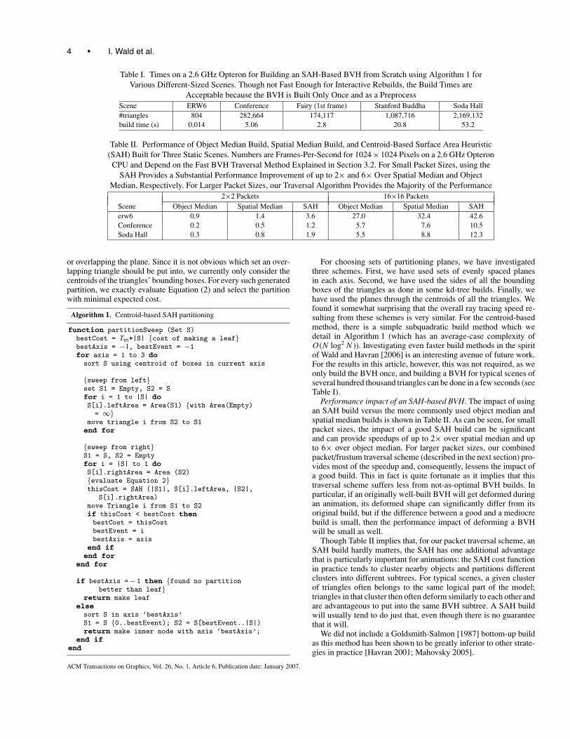


![Precise Detection in Densely Packed Scenes - arxiv.org · the state-of-the-art RetinaNet detector [27], often returns bounding boxes which partially overlap multiple objects or detections](https://static.documents.pub/doc/80x56/5d5f420388c993f62b8bc24f/precise-detection-in-densely-packed-scenes-arxivorg-the-state-of-the-art.jpg)


