RAYBURN 370 SFW To ensure safety, satisfaction and maximum service, this Cooker should be installed by a suitably qualified and competent person. The provision of a Central Heating facility, requires that the hot water systems involved, conform fully to good plumbing practice and established standards. INSTALLATION INSTRUCTIONS
Transcript
RAYBURN 370 SFW
To ensure safety, satisfaction and maximum service, this Cooker should be installed by a suitably qualified
and competent person. The provision of a Central Heating facility, requires that the hot water systems involved,
conform fully to good plumbing practice and established standards.
INSTALLATION INSTRUCTIONS
Page No.
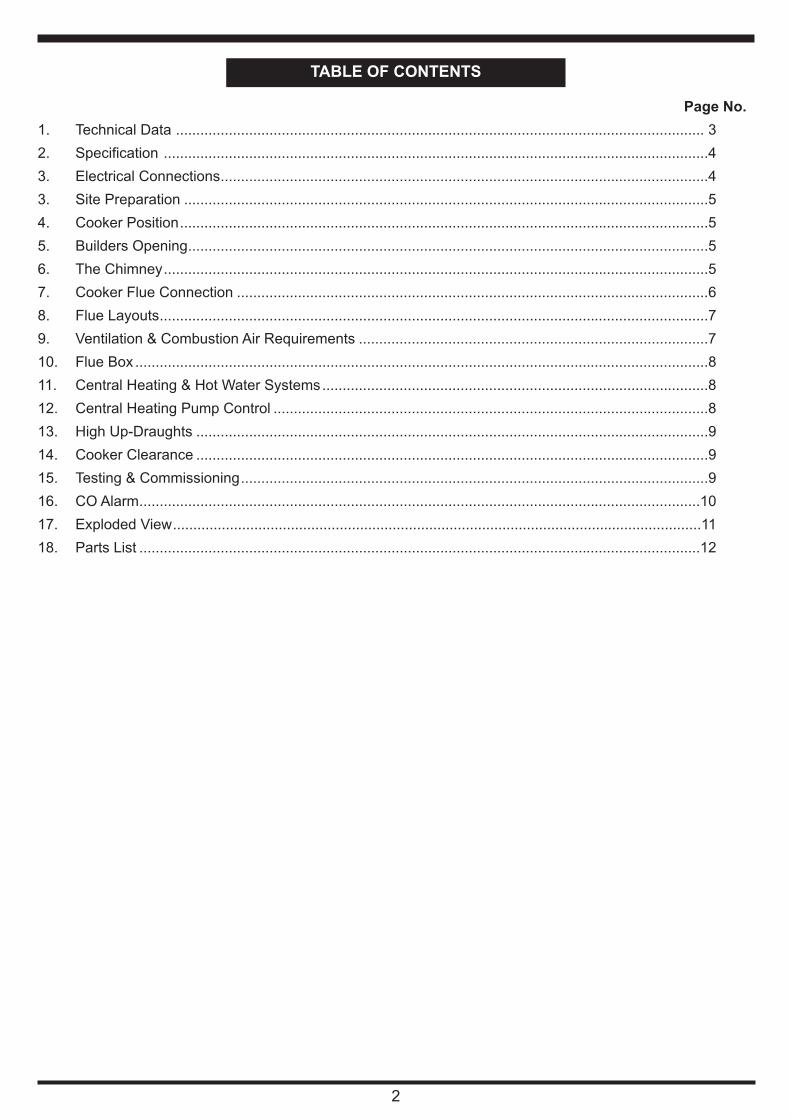
1. Technical Data .................................................................................................................................. 3
16. CO Alarm..........................................................................................................................................10
18. Parts List ..........................................................................................................................................12
Typical Refuelling Interval To Obtain Nominal Outputs: 1.0 hrs
Flue Gas Temperature At Nominal Output: 269-282oC
Flue Gas Mass Flow: 18.8-21.3 g/s
Maximum Log Length 380mm
Consumer Protection Act 1987
As responsible manufacturers, we take care to make
sure that our products are designed and constructed to
meet the required safety standards when properly in-
stalled and used.
IMPORTANT NOTICE: PLEASE READ THE ACCOM-
PANYING WARRANTY: Any alteration that is not ap-
proved by AGA, could invalidate the approval of the
appliance, operation of the warranty and could also af-
fect your statutory rights. Use only authorised replace-
ment parts.
All local regulations including those referring to
national and European standards need to be
complied with when installing the appliance.
Control of Substances - Health and Safety
Important
This appliance may contain some of the materials that
are indicated. It is the Users/Installers responsibility to
ensure that the necessary personal protective clothing
is worn when handling, where applicable, the pertinent
parts that contain any of the listed materials that could
be interpreted as being injurious to health and safety,
see below for information.
Firebricks, Fuel beds, Fuels - when handling use
disposable gloves.
Fire Cement - when handling use disposable gloves.
In case of skin contact wash immediately with plenty of
water.
Glues and Sealants - exercise caution - if these are
still in liquid form use face mask and disposable gloves.
Glass Yarn, Mineral Wool, Insulation Pads,
Ceramic Fibre, Kerosene Oil - may be harmful if
inhaled, may be irritating to skin, eyes, nose and throat.
When handling avoid inhaling and contact with skin or
eyes. Use disposable gloves, face-masks and eye pro-
tection. After handling wash hands and other exposed
parts. When disposing of the product, reduce dust with
water spray, ensure that parts are securely wrapped.
Handling Adequate facilities must be available for load-
ing, unloading and site handling.
Asbestos
This stove contains no asbestos. If there is a possibility
of disturbing any asbestos in the course of installation
then please seek guidance and use appropriate
protective equipment.
SPECIFICATION
WARNING:- THIS APPLIANCE MUST NOT BE USED WITHOUT WATER CONNECTED, OTHERWISE
DAMAGE TO THE BOILER MAY BE CAUSED AND/OR HEAT DAMAGE TO SURROUNDING
SURFACES.
General
Gross Weight: 400kg
Flue Outlet Diameter: 150mm
Max Water Pressure: 1.79 Bar
Minimum Flue Draught: 15 pa
Boiler Water Capacity: 20 Litres
*(Int.)
*(Int.)
* (Int.) Internal Thread
4
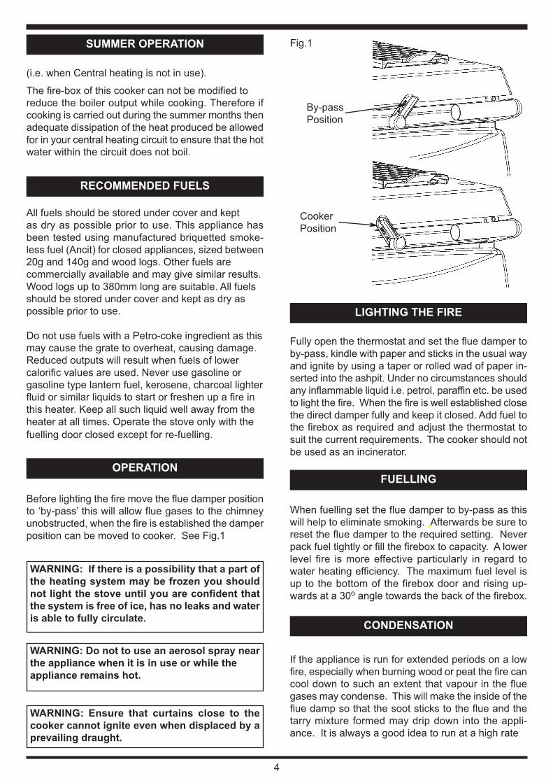
Fig.1
ELECTRICAL CONNECTIONS
The installation of any electrical services during
the installation of this cooker with boiler and the
associated heating system must be carried out
by a registered competent electrician and in
accordance with the requirements of the latest
issue of BS 7671.
The non-combustible hearth must be solid and level
and together with the walls adjacent to the cooker and
chimney, conform to current Building Regulations.
The cooker and chimney flue installation should be in
accordance with current issues of British Standards
BS EN 15287-1:2007 design, installation and com-
missioning of chimneys. BS EN 14336:2004: Heating
Systems in Buildings. Installation and commissioning
of water based heating systems. BS EN 12828: 2003;
Heating Systems in Buildings. Design of water based
heating systems. BS EN 12831: 2003; Heating Sys-
tems in Buildings. Method for calculation of the design
heat load. As applicable to the appliance. The boiler
installation section must also be in accordance with
the byelaws of the local Water Undertaking,
Regulations for the Electrical Equipment of Buildings
published by the Institute of Electrical Engineers and
any relevant requirements of the Local Authority.
Ensure that any electrical wiring is correctly earthed.
When the cooker is installed in a recess it must be
‘freestanding’ and not built-in solid at the sides. En-
sure that any combustible material e.g. kitchen furni-
ture is spaced away from the cooker to the
recommended distances. See Clearance to
Combustibles Section.
The fireplace recess should comply with current build-
ing regulations, and have an opening of 1,080mm
wide minimum, by 343mm deep minimum and
1,680mm high minimum from floor is recommended.
PLEASE NOTE: IT IS ADVISABLE TO CHECK THE
SIZE/WIDTH OF YOUR APPLIANCE BEFORE
FINALLY FIXING ANY KITCHEN UNITS SINCE
ENAMELLED CAST IRON CAN VARY IN SIZE.
The minimum chimney draught requirement at nomi-
nal total heat output is 15 Pa/.06” WG.
This appliance is not suitable for installation in a
shared flue system.
SITE PREPARATION
COOKER POSITION
BUILDERS OPENING
THE CHIMNEY
Checking existing chimney
The internal and external condition of the chimney
should be checked before the appliance is installed
and rectification made where necessary to prevent
leakage or porosity. The soundness of the chimney
which should have a minimum flue dimension of
150mm diameter can be confirmed by smoke testing
Advice on the test method can be obtained from
HETAS.
When repairing or re-using chimneys its recom-
mended that the building control office be consulted
before the commencement of work with particular
attention to the chimney height and its termination.
The chimney must be swept before installation.
Erecting New Chimney
The flue through the chimney should be formed with
pre-cast moisture and acid-resistant liners with a min-
imum internal dimension of 185mm square and all in
accordance with the current Building Regulations
(England and Wales) and in Scotland the Building
Standards (Scotland) (Consolidation) Regulations
and the Codes of Practice for chimneys and flues BS.
6461 Part 1 and BS 7566 Parts 1 to 4.
Ensure the chimney liners are free of projecting inter-
nal building jointing composition before the appliance
is installed.
Factory made Insulated Chimneys
It is recommended the chimney be ceramic lined and
comply with BS. 4543.
The minimum chimney diameter is 150mm.
IN ALL TYPES OF CHIMNEYS THE MINIMUM
HEIGHT FOR CORRECT OPERATION OF THE
COOKER IS 4.8m AND SHOULD TERMINATE
ABOVE THE ROOF IN ACCORDANCE WITH
REGIONAL STATUTORY REQUIREMENTS.
RECOMMENDED FLUE DRAUGHT - 15Pa/.06” WG
MINIMUM. THE APPLIANCE SHOULD BE
INSTALLED AND CONFORM TO THE CURRENT
CODES OF PRACTICE FOR INSTALLATION OF
DOMESTIC HEATING AND COOKING APPLI-
ANCES BURNING SOLID FUEL - BS 8303.
ALWAYS ADVISE THE USER TO CLEAN THE
COOKER FLUES IN ACCORDANCE WITH THE
OPERATING INSTRUCTIONS AND TO HAVE THE
CHIMNEY SWEPT AT A MINIMUM OF 6 MONTHLY
INTERVALS AFTER THE COOKER IS COMMIS-
SIONED. A VISUAL INSPECTION SHOULD BE
CARRIED OUT MONTHLY.
5
Where the chimney is believed to have previously
served an open fire installation it is possible that the
higher flue gas temperature from a closed appliance
may loosen deposits that were previously firmly ad-
hered, with the consequent risk of flue blockage. It is
therefore recommended that the chimney be swept a
second time within a month of regular use after instal-
lation.
WARNING: PROLONGED SOOT FORMATION MAY
RESULT IN THE FLUEWAYS BECOMING
BLOCKED AND COULD GIVE RISE TO THE RE-
LEASE OF CARBON MONOXIDE, A POISONOUS
GAS, INTO THE ROOM.
The position of available types of flue layouts are
shown in Figs. 2, 3 and 4, the cooker flue chamber is
adaptable to provide either top or back flue outlets,
by means of the reversible loose socket.
(a) Rear Flue Outlet
This must only be used where there is a brick flue
immediately behind the cooker. Provision must be
made for a condensate collecting vessel and
cleaning door. See Fig. 3.
NOTE: MAXIMUM HORIZONTAL LENGTH 150mm.
EXTENDED REAR FLUE PIPE AND BENDS
ARE NOT RECOMMENDED.
(b) Top Flue Outlet
The cooker should be connected to the main flue
via a 150mm minimum diameter cast iron pipe or
appropriately sized vitreous enamelled mild steel
pipe and be sealed to the cooker flue chamber
with soft rope and fire cement.
Any bends in the flue pipe must be not less than
135º (45º from horizontal) and be complete with
a cleaning door.
COOKER FLUE CONNECTIONFig. 2
DESN 515206
Fig. 3
Fig. 4
DESN 515207
DESN 515208 A
A minimum 6” vertical length of flue pipe must be fitted
before any bend is included.
6
FLUE LAYOUTS
In Fig. 2. the cooker is installed in an existing recess.
There must be a clearance of not less than 150mm
between the top of the flue pipe and any overhanging
brickwork.
Any cavities or pockets above the register plate
should as far as possible be filled and if necessary
the flue pipe should be extended into the throat of the
chimney and soot door provided for chimney sweep-
ing.
If a flue liner or insulated chimney is used, the size
should not be less than 150mm diameter.
There are two Isokern pumice liners which are also
recommended. One is the standard 175mm diameter
and the other is a 170mm thin wall. The thin wall has
a smaller outer diameter and is designed to fit an ex-
isting chimney system. Both have a lifetime guaran-
tee.
In Fig. 3, the cooker is connected direct to a brick flue.
Horizontal pipe runs between cooker and brick flue
must not be used.
In Fig. 4, the cooker is connected to an existing brick
flue with a length of flue pipe. Square bends and hor-
izontal runs must not be used. There must be a
cleaning door at every bend.
NOTE: WHATEVER METHOD OF INSTALLATION IS
EMPLOYED, AIR MUST NOT BE ALLOWED TO
ENTER THE CHIMNEY EXCEPT THROUGH THE
COOKER. ALL JOINTS MUST BE AIR-TIGHT.
If the chimney is unlined, and there is any doubt about
its condition, it should be lined in accordance with cur-
rent Building Regulations.
PROVISION MUST ALWAYS BE MADE FOR
SWEEPING THE CHIMNEY.
IMPORTANT: CEMENT TYPE PIPES AND FIT-
TINGS MUST NOT BE USED WITHIN 2m. OF THE
COOKER. CHIMNEYS OF PLAIN PIPE ARE NOT
RECOMMENDED BUT CERTAIN PROPRIETARY
MAKES OF INSULATED CHIMNEY ARE SUITABLE.
It is imperative that there is sufficient air supply to thecooker in order to support correct combustion. Theair supply to this appliance must comply with currentt Building Regulations. The minimum effective air requirement for this appliance is 91.3cm2.
7
VENTILATION & COMBUSTION AIR
REQUIREMENTS
This increases to 141.1cm2 where a flue draught sta-biliser is fitted. If another appliance is fitted in an ad-jacent room it will be necessary to calculate anadditional air supply.
All materials used in the manufacture of air vents
should be such that the vent is dimensionally stable,
corrosion resistant, and no provision for closure. The
effective free area of any vent should be ascertained
before installation. The effect of any grills should be
allowed for when determining the effective free area
of any vent.
Air vents direct to the outside of the building should
be located so that any air current produced will not
pass through normally occupied areas of the room.
An air vent outside the building should not be located
less than the dimensions specified within the Building
Regulations and B.S. 8303: Part 1 from any part of
any flue terminal. These air vents must also be satis-
factorily fire proofed as per Building Regulations and
B.S. 8303: Part 1.
Air vents in internal walls should not communicate
with bedrooms, bedsits, toilets, bathrooms or rooms
containing a shower.
Air vents traversing cavity walls should include a con-
tinuous duct across the cavity. The duct should be in-
stalled in such a manner as not to impair the weather
resistance of the cavity.
Joints between air vents and outside walls should be
sealed to prevent the ingress of moisture. Existing air
vents should be of the correct size and unobstructed
for the appliance in use. If there is an extraction fan
fitted in adjacent rooms where this appliance is fitted,
additional air vents may be required to alleviate the
possibility of spillage of products of combustion from
the appliance/flue while the fan is in operation. There
must not be an extractor fan fitted in the same room
as the appliance.
Where such an installation exists, a test for spillage
should be made with the fan or fans and other appli-
ances using air in operation at full rate, (i.e.extraction
fans, tumble dryers) with all external doors and win-
dows closed.
If spillage occurs following the above operation, an
additional air vent of sufficient size to prevent this oc-
currence should be installed.
8
Fig.5
Especially Airtight Properties:-
If the cooker is being fitted in a property where the
design air permeability is less than 5m3 / (h.m2) (nor-
mally newer properties built from 2006), then a per-
manent ventilation must be fitted to provide 550mm2
of ventilation for each kW of rated output. If a draught
stabiliser is also fitted then the requirement is
850mm2 per kW of rated output.
Apply fire cement to the socket in the hob. Attach a
short length of 6” (150mm) I.D. pipe approx. 10”
(250mm) long to the outlet of the flue box by means
of fire cement. Place the flue box on the hob and the
pipe into the wall and consolidate the fluebox and pipe
into the fire cement. Apply 3 or 4 coils of 10mm (1/2’)
insulating rope to the pipe and fill the wall cavity with
fire cement. (See fig. 5).
FLUE BOX
CENTRAL HEATING ANDHOT WATER SYSTEM
THIS APPLIANCE MUST NOT BE USED WITHOUT
WATER CONNECTED.
It is recommended that a 190 litre (40 galls) indirect
hot water storage cylinder of the double feed type e.g.
(Complying with BS. 1566 Part 1:DF Type 10) should
be lagged and fixed vertically as near as possible to
the cooker.
The 28mm minimum diameter primary flow and return
pipes must not exceed 10m in length and pipes longer
than 5m must be lagged.
Ensure that the flow pipe has an open vent and rises
continuously from the boiler to the cylinder to ensure
good gravity circulation.
In combined systems, the water draw-off pipes to the
taps must be dead-leg connection from the vent/ex-
pansion pipe.
There are only two boiler tappings on this cooker and
a typical design layout is shown in Fig. 6.
An injector tee is provided which must be fitted to en-
sure adequate primary flow circulation when the water
circulator is operating, otherwise there may be a lack
of domestic hot water. The heating flow and return
pipes may be 22mm, the return pipe being connected
to the 28mm primary return by the injector tee, and
the tee outlet connected to the boiler return pipe.
All installations must be fitted with a drain tap at the
lowest point of the system.
Inhibitor
A corrosion inhibitor MUST be added to the heating
system to protect the heat exchanger and pipework.
Inhibitor must also be replaced if the system is
drained after installation. As a precaution, the heating
system MUST also be flushed out prior to the addition
of the inhibitor to ensure any flux, debris is removed.
Typical Central Heating/Hot
Water System
Fig.6
CENTRAL HEATING PUMP CONTROL
The central heating pump must be controlled by fitting
a pipe thermostat on the flow pipe as close as possi-
ble to the cooker. If it is used on its own it should be
set to approx. 55oC
9
Alternatively the pipe thermostat (A) can be wired in
parallel with another pipe thermostat (b) which is
wired in series with a timeclock and room thermostat.
In this instance priority can be given to hot water by
setting the pipe thermostat (A) to approx. 85oC used
only to prevent boiling, the pipe thermostat (B) should
be set to approx. 55oC.
AT LEAST ONE RADIATOR (USUALLY THE BATH-
ROOM) SHOULD NOT BE FITTED WITH A TRV
(THERMOSTATIC RADIATOR VALVE), TO ACT AS
A HEAT LEAK, SHOULD THE BOILER OVERHEAT
AND THE PUMP FAIL TO START.
Fig.7
HIGH UPDRAUGHTS
Tall chimneys may develop excessively high up-
draughts which prevent the appliance operating cor-
rectly.
It is recommended that a proprietary brand adjustable
flue draught stabiliser having an openable cross sec-
tional area of 182.5sq cm (6”ø pipe) be fitted above
the flue pipe connection, either in the brickwork or into
a right angle ‘T’; fitting in the flue pipe position that will
not inconvenience appliance operation or mainte-
nance.
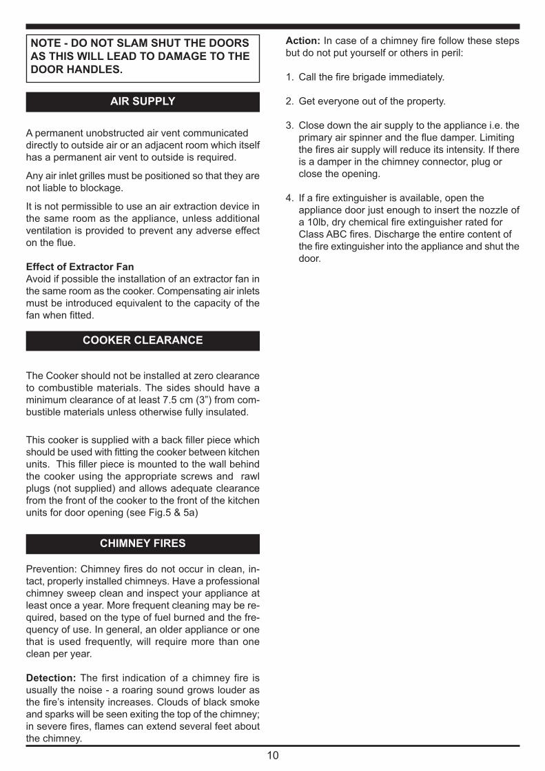
COOKER CLEARANCE
The Cooker should not be installed at zero clearance
to combustible materials. The sides should have a
minimum clearance of at least 75 mm (3”) from com-
This cooker is supplied with a back filler piece which
should be used with fitting the cooker between
kitchen units. This filler piece is mounted to the wall
behind the cooker using the appropriate screws and
rawl plugs (not supplied) and allows adequate clear-
ance from the front of the cooker to the front of the
kitchen units for door opening (see Fig.8 & 8a)
Fig.8
Fig.8a
Gap between Cooker & Kitchen units
must be filled using a filler strip
Cooker front must be
kept in line with front
of kitchen unit.
Back filler piece
WorktopWorktop
75 75
TESTING & COMMISSIONING
After completing the installation, the heating contrac-
tor should demonstrate to the user the operation of
the appliance and the routine cleaning method.
The protective grease should be removed from the
hotplate before lighting.
Check that the system is full of water and free from
air locks.
For the first couple of days do not overfire. The cast
iron inside the cooker will build up heat gradually and
overfiring may cause damage.
NOTE: SMOKE/SMELL EMITTED DURING INITIAL
USAGE
Some parts of the cooker have been coated with a
light covering of protective oil. During initial operation
of the cooker, this may cause smoke/smell to be emit-
ted and is normal and not a fault with the appliance,
it is therefore advisable to open doors and or windows
to allow for ventilation. Lift the lids to prevent staining
the linings.
Ensure all parts are fitted in accordance with the in-
structions.
On completion of the installation allow a suitable pe-
riod of time for any fire cement and mortar to dry out,
before lighting the stove. Once the stove is under fire
check all seals for soundness and check that the flue
is functioning correctly and that all products of com-
bustion are vented safely to atmosphere via the chim-
ney terminal.
On completion of the installation and commissioning
ensure that the operating instructions for the stove are
left with the customer. Advise the user what to do
should smoke or fumes be emitted from the stove.
Building Regulations require that whenever a new or
replacement fixed solid fuel or wood/biomass appli-
ance is installed in a dwelling a carbon monoxide
alarm must be fitted in the same room as the appli-
ance. Further guidance on the installation of the car-
bon monoxide alarm is available in BS EN
50292:2002 and from the alarm manufacturer’s
instructions.
CO ALARM
10
WARNING:-
If the CO Alarm sounds unexpectedly:-
1. Open Doors and windows to ventilate the
room and then leave the premises.
2. Let the fire go out.
Provision of an alarm must not be considered a
substitute for either installing the appliance cor-
rectly or ensuring regular servicing and mainte-
nance of the appliance and chimney system.
Your installer should have fitted a CO alarm in the
same room as the appliance. If the alarm sounds
unexpectedly, follow the instructions given under
“Warning Note” below.
11
EXPLODED VIEW
12
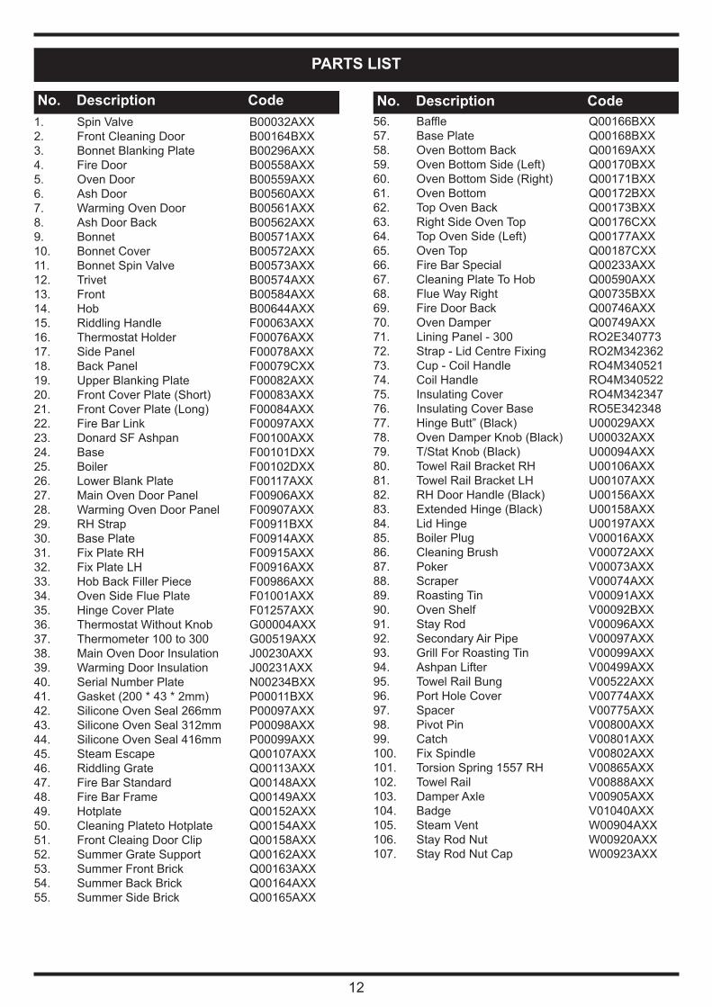
PARTS LIST
1. Spin Valve B00032AXX
2. Front Cleaning Door B00164BXX
3. Bonnet Blanking Plate B00296AXX
4. Fire Door B00558AXX
5. Oven Door B00559AXX
6. Ash Door B00560AXX
7. Warming Oven Door B00561AXX
8. Ash Door Back B00562AXX
9. Bonnet B00571AXX
10. Bonnet Cover B00572AXX
11. Bonnet Spin Valve B00573AXX
12. Trivet B00574AXX
13. Front B00584AXX
14. Hob B00644AXX
15. Riddling Handle F00063AXX
16. Thermostat Holder F00076AXX
17. Side Panel F00078AXX
18. Back Panel F00079CXX
19. Upper Blanking Plate F00082AXX
20. Front Cover Plate (Short) F00083AXX
21. Front Cover Plate (Long) F00084AXX
22. Fire Bar Link F00097AXX
23. Donard SF Ashpan F00100AXX
24. Base F00101DXX
25. Boiler F00102DXX
26. Lower Blank Plate F00117AXX
27. Main Oven Door Panel F00906AXX
28. Warming Oven Door Panel F00907AXX
29. RH Strap F00911BXX
30. Base Plate F00914AXX
31. Fix Plate RH F00915AXX
32. Fix Plate LH F00916AXX
33. Hob Back Filler Piece F00986AXX
34. Oven Side Flue Plate F01001AXX
35. Hinge Cover Plate F01257AXX
36. Thermostat Without Knob G00004AXX
37. Thermometer 100 to 300 G00519AXX
38. Main Oven Door Insulation J00230AXX
39. Warming Door Insulation J00231AXX
40. Serial Number Plate N00234BXX
41. Gasket (200 * 43 * 2mm) P00011BXX
42. Silicone Oven Seal 266mm P00097AXX
43. Silicone Oven Seal 312mm P00098AXX
44. Silicone Oven Seal 416mm P00099AXX
45. Steam Escape Q00107AXX
46. Riddling Grate Q00113AXX
47. Fire Bar Standard Q00148AXX
48. Fire Bar Frame Q00149AXX
49. Hotplate Q00152AXX
50. Cleaning Plateto Hotplate Q00154AXX
51. Front Cleaing Door Clip Q00158AXX
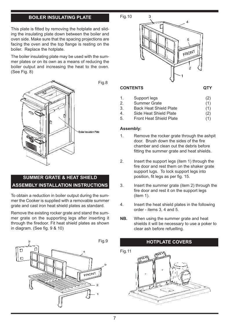
52. Summer Grate Support Q00162AXX
53. Summer Front Brick Q00163AXX
54. Summer Back Brick Q00164AXX
55. Summer Side Brick Q00165AXX
56. Baffle Q00166BXX
57. Base Plate Q00168BXX
58. Oven Bottom Back Q00169AXX
59. Oven Bottom Side (Left) Q00170BXX
60. Oven Bottom Side (Right) Q00171BXX
61. Oven Bottom Q00172BXX
62. Top Oven Back Q00173BXX
63. Right Side Oven Top Q00176CXX
64. Top Oven Side (Left) Q00177AXX
65. Oven Top Q00187CXX
66. Fire Bar Special Q00233AXX
67. Cleaning Plate To Hob Q00590AXX
68. Flue Way Right Q00735BXX
69. Fire Door Back Q00746AXX
70. Oven Damper Q00749AXX
71. Lining Panel - 300 RO2E340773
72. Strap - Lid Centre Fixing RO2M342362
73. Cup - Coil Handle RO4M340521
74. Coil Handle RO4M340522
75. Insulating Cover RO4M342347
76. Insulating Cover Base RO5E342348
77. Hinge Butt” (Black) U00029AXX
78. Oven Damper Knob (Black) U00032AXX
79. T/Stat Knob (Black) U00094AXX
80. Towel Rail Bracket RH U00106AXX
81. Towel Rail Bracket LH U00107AXX
82. RH Door Handle (Black) U00156AXX
83. Extended Hinge (Black) U00158AXX
84. Lid Hinge U00197AXX
85. Boiler Plug V00016AXX
86. Cleaning Brush V00072AXX
87. Poker V00073AXX
88. Scraper V00074AXX
89. Roasting Tin V00091AXX
90. Oven Shelf V00092BXX
91. Stay Rod V00096AXX
92. Secondary Air Pipe V00097AXX
93. Grill For Roasting Tin V00099AXX
94. Ashpan Lifter V00499AXX
95. Towel Rail Bung V00522AXX
96. Port Hole Cover V00774AXX
97. Spacer V00775AXX
98. Pivot Pin V00800AXX
99. Catch V00801AXX
100. Fix Spindle V00802AXX
101. Torsion Spring 1557 RH V00865AXX
102. Towel Rail V00888AXX
103. Damper Axle V00905AXX
104. Badge V01040AXX
105. Steam Vent W00904AXX
106. Stay Rod Nut W00920AXX
107. Stay Rod Nut Cap W00923AXX
No. Description Code No. Description Code
13
NOTES
NOTES
14
15
NOTES
With AGA Rangemster’s policy of continuous prod-
uct improvement, the Company reserves the right
to change specifications and make modifications to
the appliance described at any time.
Manufactured by
AGA Rangemaster
Station Road
Ketley Telford
Shropshire TF1 5AQ
England
www.rayburn-web.co.uk
www.agacookshop.co.uk
N00636AXX DP140901
RAYBURN 370 SFW
This appliance is hot while in operation and retains its heat for a long period of time after use.
Children, aged or infirm persons should be supervised at all times and should not be allowed
to touch the hot working surfaces while in use or until the appliance has thoroughly cooled.
When using the cooker in situations where children, aged and/or infirm persons are present a fireguard must be used to prevent accidental contact with the stove. The fireguardshould be manufactured in accordance with BS 8423:2002.
18. Use of Ovens .....................................................................................................................................8
22. Opening Cooker Door ........................................................................................................................9
23. Air Supply.........................................................................................................................................10
26. CO Alarms ........................................................................................................................................11