272
| Date post: | 13-Aug-2015 |
| Category: |
Engineering |
| Upload: | shaban-ratib |
| View: | 44 times |
| Download: | 2 times |
���
����
�
������������� ��
����������� �������������
�������������������

Doc nr: 3/001 59-EN/LZT 720 0011 Uen Rev A
Ericsson GSM System EN/LZT 720 0011 R1A
RBS 2206 Maintenance Manual

BINDER LABEL 1 (1)Uppgjord (även faktaansvarig om annan) - Prepared (also subject responsible if other) Nr - No.
SG/ERA/SRB/ZP Per Olof Höglund 4/001 59-EN/LZT 720 0011 UenDokansv/Godkänd - Doc respons/Approved Kontr - Checked Datum - Date Rev File
ERA/SRB/Z 2001-06-29 A
N:\h\HiCap_OIS\Manuals\RelMaintenanceManual\work items\4_00159ENLZT7200011R1A.doc
98 65
Fontsize 10
Fontsize 10HEADING
XXX
LZN xxx xxx
R-state
28
38
47
54
RBS 2206
MaintenanceManual
Ericsson GSMSystem
EN/LZT 720 0011R1A
Fontsize 12
Cutting mark
Fontsize 14

CAPTION LISTDocument No.
2/001 59-EN/LZT 720 0011
RBS 2206Maintenance ManualDate
2001-06-29Rev
A
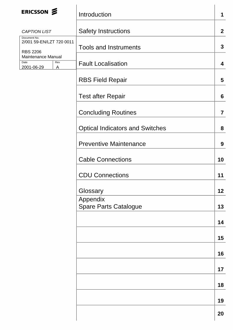
Introduction 1
Safety Instructions 2
Tools and Instruments 3
Fault Localisation 4
RBS Field Repair 5
Test after Repair 6
Concluding Routines 7
Optical Indicators and Switches 8
Preventive Maintenance 9
Cable Connections 10
CDU Connections 11
Glossary 12
AppendixSpare Parts Catalogue 13
14
15
16
17
18
19
20


E RBS 2206 Maintenance Manual
RBS 2206 Maintenance Manual© Ericsson Radio Systems AB — All Rights Reserved —
EN/LZT 720 0011 R1A
2001-07-031 (201)© Ericsson Radio Systems AB
— All Rights Reserved —
RBS 2206 Maintenance Manual
Due to continued progress in methodology, design and manufacturing,the contents of this document are subject to revision without notice.
2 (201) EN/LZT 720 0011 R1A
2001-07-03© Ericsson Radio Systems AB
— All Rights Reserved —
RBS 2206 Maintenance Manual
Contents1 Introduction...................................................................................................7
1.1 Product Overview ...................................................................................7
1.2 RBS 2000 Library Overview ...................................................................7
1.3 Target Group ........................................................................................... 8
1.4 Maintenance Process Overview..............................................................9
1.5 How to Use this Manual ..........................................................................14
1.6 Release History ....................................................................................... 15
2 Safety Instructions........................................................................................17
2.1 Warnings..................................................................................................17
2.2 Notes........................................................................................................18
2.3 Beryllium Oxide (BeO).............................................................................19
2.4 Electrical Hazards....................................................................................21
2.5 Batteries...................................................................................................24
2.6 Working at Heights..................................................................................26
2.7 Radio Frequency Radiation.....................................................................28
2.8 Other Hazards ......................................................................................... 29
3 Tools and Instruments .................................................................................31
3.1 Test Equipment ...................................................................................... 31
3.2 OMT Kit .................................................................................................. 31
3.3 Personal Tool Kit .....................................................................................33
3.4 References...............................................................................................35
4 Fault Localisation..........................................................................................37
4.1 Introduction..............................................................................................37
4.2 Fault Lists ................................................................................................ 38
4.3 ALNA/TMA A and ALNA/TMA B ............................................................. 40
4.4 Antenna....................................................................................................41
4.5 Battery......................................................................................................45
4.6 Battery Temp Sensor...............................................................................47
4.7 BDM or BFU............................................................................................47
4.8 CDU.........................................................................................................50
EN/LZT 720 0011 R1A
2001-07-033 (201)© Ericsson Radio Systems AB
— All Rights Reserved —
RBS 2206 Maintenance Manual
4.9 CDU Bus/IOM bus...................................................................................52
4.10 CDU CXU RXA Cable and CDU CXU RXB Cable...............................52
4.11 CDU RX in Cable .................................................................................. 55
4.12 CXU....................................................................................................... 58
4.13 CXU DC Cable ...................................................................................... 58
4.14 CXU dTRU RXA Cable and CXU dTRU RXB Cable............................60
4.15 DXU....................................................................................................... 64
4.16 Environment...........................................................................................66
4.17 EOM Bus............................................................................................... 66
4.18 EPC Bus/Power Communication Loop..................................................66
4.19 External Alarms ..................................................................................... 70
4.20 Fan.........................................................................................................70
4.21 FCU........................................................................................................72
4.22 Flash Card.............................................................................................74
4.23 PSU........................................................................................................76
4.24 PSU DC Cable.......................................................................................78
4.25 RBS DB................................................................................................. 81
4.26 TMA CM.................................................................................................83
4.27 TMA CM Cable......................................................................................85
4.28 TRU, dTRU or ATRU.............................................................................85
4.29 Y Link.....................................................................................................89
5 RBS Field Repair...........................................................................................93
5.1 Local/remote Mode..................................................................................93
5.2 ACCU.......................................................................................................95
5.3 Antenna Feeder.......................................................................................98
5.4 Bias Injector.............................................................................................99
5.5 CDU.........................................................................................................100
5.6 CDU Bus..................................................................................................102
5.7 CDU-CXU and the TRU-CXU RX Cables...............................................104
5.8 CDU-TRU TX Cables .............................................................................. 105
5.9 CNU.........................................................................................................106
4 (201) EN/LZT 720 0011 R1A
2001-07-03© Ericsson Radio Systems AB
— All Rights Reserved —
RBS 2206 Maintenance Manual
5.10 CXU....................................................................................................... 107
5.11 DCCU.....................................................................................................108
5.12 DC Filter.................................................................................................109
5.13 dTRU......................................................................................................111
5.14 DXU....................................................................................................... 111
5.15 DXU Backplane ..................................................................................... 112
5.16 ESB Cable.............................................................................................114
5.17 Fans.......................................................................................................115
5.18 FCU........................................................................................................116
5.19 Flash Card.............................................................................................117
5.20 IDB.........................................................................................................117
5.21 IDM........................................................................................................ 118
5.22 PSU........................................................................................................119
5.23 PSU DC Cable.......................................................................................120
5.24 RX Antenna Feeder...............................................................................121
5.25 TMA CM.................................................................................................122
5.26 TRU........................................................................................................123
5.27 TRU Backplane......................................................................................124
5.28 TX Antenna Feeder ...............................................................................125
6 Test after Repair............................................................................................127
6.1 Preconditions...........................................................................................127
6.2 Test Call...................................................................................................127
7 Concluding Routines....................................................................................131
7.1 Before Leaving the Site...........................................................................131
7.2 Report of Finished Work..........................................................................131
7.3 Repair Delivery Note – “Blue Tag” ..........................................................132
7.4 Handling of Replaced Parts and RUs.....................................................132
7.5 Transport of a Repairable Unit................................................................134
7.6 Trouble Report on Equipment or on this Manual....................................134
8 Optical Indicators and Switches ................................................................. 139
8.1 Indicator Types........................................................................................139
EN/LZT 720 0011 R1A
2001-07-035 (201)© Ericsson Radio Systems AB
— All Rights Reserved —
RBS 2206 Maintenance Manual
8.2 Units with optical indicators and switches ..............................................139
8.3 ACCU.......................................................................................................139
8.4 CDU-F......................................................................................................140
8.5 CDU-G.....................................................................................................140
8.6 CXU......................................................................................................... 141
8.7 DCCU.......................................................................................................142
8.8 dTRU........................................................................................................143
8.9 DXU......................................................................................................... 144
8.10 FCU........................................................................................................146
8.11 IDM........................................................................................................ 146
8.12 PSU........................................................................................................147
8.13 RBS Status Panel..................................................................................148
8.14 TMA CM.................................................................................................149
9 Preventive Maintenance...............................................................................149
9.1 Preventive Maintenance Process............................................................151
9.2 Determining Preventive Maintenance Intervals ......................................151
9.3 Maintaining Antenna Systems ................................................................152
9.4 Maintaining Batteries ..............................................................................153
9.5 Replacing Fans .......................................................................................155
9.6 Replacing Door Filter ..............................................................................155
9.7 Performing Concluding Routines.............................................................156
10 Cable Connections......................................................................................157
10.1 Power Cables ........................................................................................ 157
10.2 Opto Cables...........................................................................................157
10.3 Backplane Cables..................................................................................159
11 CDU Connections........................................................................................164
11.1 Inserting and Extracting RUs.................................................................165
11.2 CDU to Connection Field - General ......................................................167
11.3 CDU to Connection Field RBS 2206.....................................................167
11.4 CDU Antenna Connection Field RBS 2206 .......................................... 173
12 Glossary.......................................................................................................187
6 (201) EN/LZT 720 0011 R1A
2001-07-03© Ericsson Radio Systems AB
— All Rights Reserved —
Introduction
1 IntroductionThis Maintenance Manual is valid for the radio base station RBS 2206for Ericsson GSM System release R8.
The purpose of the manual is to provide the information necessary forfirst line maintenance. First line maintenance includes the followingactivities:
• Repairs that entail replacement on site. Only Replaceable Units(RUs) are handled.
• Preventive maintenance.
The instructions apply only to the Radio Base Station (RBS) connectedto a Base Station Controller (BSC), and it is assumed that the RBS isinstalled and in operation.
The instructions in this manual presuppose that the replaced units arealways put into operation.
1.1 Product Overview
��������
���� ��� ������
���������
��
��
���
���
��
��������
��
��� ���������
��� ���������
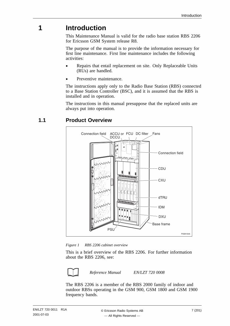
Figure 1 RBS 2206 cabinet overview
This is a brief overview of the RBS 2206. For further informationabout the RBS 2206, see:
Reference Manual EN/LZT 720 0008
The RBS 2206 is a member of the RBS 2000 family of indoor andoutdoor RBSs operating in the GSM 900, GSM 1800 and GSM 1900frequency bands.
EN/LZT 720 0011 R1A
2001-07-037 (201)© Ericsson Radio Systems AB
— All Rights Reserved —
Introduction
The RBS 2206 is designed for indoor installation. It consists of a radiocabinet mounted on a base frame.
Cable entries for feeders, transmission and power cables areconcentrated to the upper part of the cabinet on connection fields, whichare covered by the cabinet door.
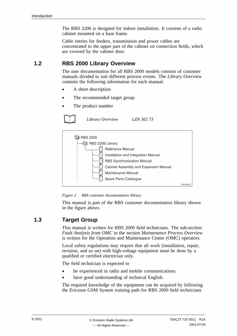
1.2 RBS 2000 Library OverviewThe user documentation for all RBS 2000 models consists of customermanuals divided to suit different process events. The Library Overviewcontains the following information for each manual:
• A short description
• The recommended target group
• The product number
Library Overview LZN 302 73
���!��"�
������ ���#�
��������������$������#�
�����% &���'�����#�
�(���������(�%���)*+�����#�
���� ���#�
�+������������$#�
����,���
����,,�-�.�(��%
Figure 2 RBS customer documentation library
This manual is part of the RBS customer documentation library shownin the figure above.
1.3 Target GroupThis manual is written for RBS 2000 field technicians. The sub-sectionFault Analysis from OMC in the section Maintenance Process Overviewis written for the Operation and Maintenance Centre (OMC) operators.
Local safety regulations may require that all work (installation, repair,revision, and so on) with high-voltage equipment must be done by aqualified or certified electrician only.
The field technician is expected to
• be experienced in radio and mobile communications.• have good understanding of technical English.
The required knowledge of the equipment can be acquired by followingthe Ericsson GSM System training path for RBS 2000 field technicians
8 (201) EN/LZT 720 0011 R1A
2001-07-03© Ericsson Radio Systems AB
— All Rights Reserved —
Introduction
1.4 Maintenance Process OverviewThe purpose of this chapter is to provide an overview of themaintenance process and describe how to perform the correctmaintenance procedures.
1.4.1 General
RBS 2000 radio base stations are administered and controlled by theBSC. There is a master/slave relationship between the BSC and theRBS, and the BSC has an overview of the status of the radio networkand its resources.
The BSC manages the O&M of the RBS across the Abis Interface. TheRBS equipment is seen as an MO by the BSC. This is a way ofdescribing the RBS, in a functional way and as a logical model, in theBSC. All O&M actions are based on this logical model structurecreated in the BSC. An MO does not necessarily have a one-to-onerelationship with a physical unit in the RBS.
The MO, describing RBS 2000 (G12), is divided into two sub-classes:AO and SO. The SO is the abstract sub-class of the MO that owns thehardware. The AO only handles functions.
The RBS can be set in local or remote mode. Local mode means thatthe RBS has been disconnected and isolated from the BSC, while inremote mode the RBS is controlled by the BSC.
When the RBS is in remote mode, the BSC acts as a master in the BSC-RBS relationship and all RBS maintenance actions are ordered by theBSC. Faults in the RBS are reported to the BSC on an MO basis. Allfaults reported by the MOs in the RBS are stored in the BSC error log.
Tests on MOs with RBS hardware can be ordered by a BSC operator inorder to check the status of the RBS. The operator can also test theconnection between the BSC and a TRU in the RBS by ordering a looptest. A test pattern is passed through the loop created between the BSCand one specific time slot in a specified TRU.
The RBS contains test and supervision functions that detectmalfunctions and report them to the BSC. Tests and supervision areperformed on an MO basis, which means that the different MOssupervise their own equipment.
Statistics are collected on an MO basis in the BSC, for example, thenumber of call setup attempts, or the number of abnormally terminatedcalls.
EN/LZT 720 0011 R1A
2001-07-039 (201)© Ericsson Radio Systems AB
— All Rights Reserved —
Introduction
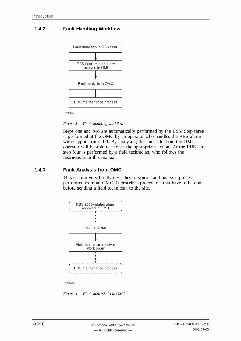
1.4.2 Fault Handling Workflow
��������
�#������� ����������,���
����,���/������������ ��0�����1��
�#����%������1��
�������� ��+�� ���
Figure 3 Fault handling workflow
Steps one and two are automatically performed by the BSS. Step threeis performed at the OMC by an operator who handles the RBS alarmwith support from OPI. By analysing the fault situation, the OMCoperator will be able to choose the appropriate action. At the RBS site,step four is performed by a field technician, who follows theinstructions in this manual.
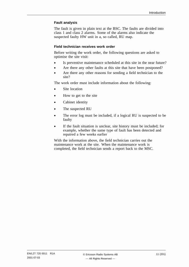
1.4.3 Fault Analysis from OMC
This section very briefly describes a typical fault analysis process,performed from an OMC. It describes procedures that have to be donebefore sending a field technician to the site.
����"���
�������� &� ���� ��0��2��3������
�������� ��+�� ���
�#����%���
����,���/������������ ��0�����1��
Figure 4 Fault analysis from OMC
10 (201) EN/LZT 720 0011 R1A
2001-07-03© Ericsson Radio Systems AB
— All Rights Reserved —
Introduction
Fault analysis
The fault is given in plain text at the BSC. The faults are divided intoclass 1 and class 2 alarms. Some of the alarms also indicate thesuspected faulty HW unit in a, so called, RU map.
Field technician receives work order
Before writing the work order, the following questions are asked tooptimise the site visit:
• Is preventive maintenance scheduled at this site in the near future?• Are there any other faults at this site that have been postponed?• Are there any other reasons for sending a field technician to the
site?
The work order must include information about the following:
• Site location
• How to get to the site
• Cabinet identity
• The suspected RU
• The error log must be included, if a logical RU is suspected to befaulty
• If the fault situation is unclear, site history must be included; forexample, whether the same type of fault has been detected andrepaired a few weeks earlier
With the information above, the field technician carries out themaintenance work at the site. When the maintenance work iscompleted, the field technician sends a report back to the MSC.
EN/LZT 720 0011 R1A
2001-07-0311 (201)© Ericsson Radio Systems AB
— All Rights Reserved —
Introduction
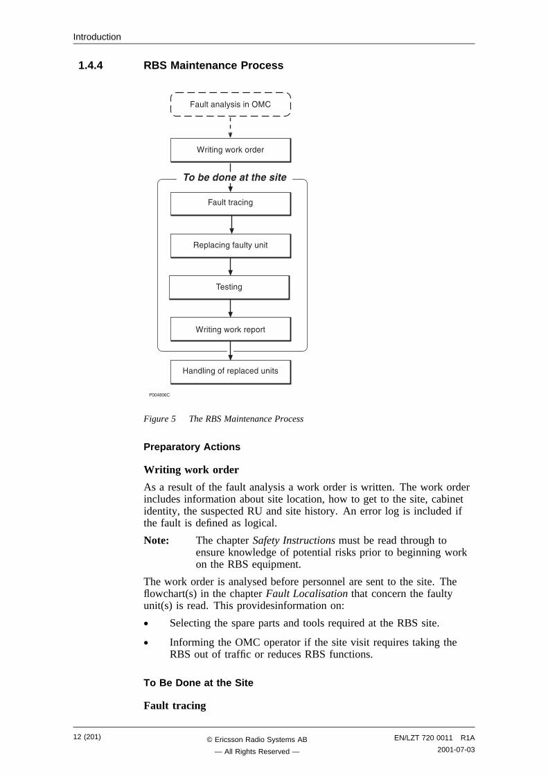
1.4.4 RBS Maintenance Process
������-�
4����$�2��3������
�#����� �$
��+� �$��#��%�#��
�����$
4����$�2��3���+���
�#����%������1��
5���$������+� ���#���
������������������
Figure 5 The RBS Maintenance Process
Preparatory Actions
Writing work order
As a result of the fault analysis a work order is written. The work orderincludes information about site location, how to get to the site, cabinetidentity, the suspected RU and site history. An error log is included ifthe fault is defined as logical.
Note: The chapter Safety Instructions must be read through toensure knowledge of potential risks prior to beginning workon the RBS equipment.
The work order is analysed before personnel are sent to the site. Theflowchart(s) in the chapter Fault Localisation that concern the faultyunit(s) is read. This providesinformation on:
• Selecting the spare parts and tools required at the RBS site.
• Informing the OMC operator if the site visit requires taking theRBS out of traffic or reduces RBS functions.
To Be Done at the Site
Fault tracing
12 (201) EN/LZT 720 0011 R1A
2001-07-03© Ericsson Radio Systems AB
— All Rights Reserved —

Introduction
The chapter Fault Localisation provides methods for finding the faultyunit in the RBS that causes the alarm reported to the BSC. Forexample, when the work order denotes that a TRU is faulty, faultlocalisation will point out the position of the faulty TRU.
All alarms given in the RU maps correspond to a section in the chapterFault Localisation.
Replacing faulty unit
The chapter RBS Field Repair describes how to replace a faulty unit.
Testing
The RBS is tested before the field technician leaves the site. Thechapter Test after Repair describes how to verify that the RBS isfunctioning properly.
Writing work report
The chapter Concluding Routines provides information on the differentadministrative routines that must be performed before leaving the site.
After Maintenance
Handling of replaced units
The chapter Concluding Routines describes which units are repairableand which are disposable and the different administrative routinesconnected to both.
1.4.5 Fault Cases
The purpose of this section is to explain the different fault cases thatcan arise in the RBS 2000. This forms the basis for choosing betweendifferent methods when localising a detected fault.
• Unambiguous indication with an indicator and an RU map.• Unambiguous indication with an RU map only.• Unit that is unambiguously indicated, but consists of several
replaceable parts.• Logical RU indicated.
Note that the BSS only pinpoints one RU in the RU Map.
Indication with an indicator and an RU Map
Examples of units DXU, dTRU, CXU, PSU and CDU
Method of localisation The work order states which unit isaffected. When the cabinet is opened, ared Fault indicator will be on in the faultyunit. If this indicator should be defective,only an RBS fault indicator will be on. Inthis case, the OMT is used to localise thefaulty unit.
EN/LZT 720 0011 R1A
2001-07-0313 (201)© Ericsson Radio Systems AB
— All Rights Reserved —
Introduction
Indication with an RU Map
Examples of units RX cables
Method of localisation The work order states the unit concerned.The Maintenance Manual is used to findout where the unit is located.
Indication of Units that Consist of Several Replaceable Parts
Examples of units Fan unit
Method of localisation The work order states which unit isaffected. The OMT is used to identifywhich parts are faulty, for example, whichfan is faulty.
Logical RU Indicated
The logical RU is identified when it is not obvious which physical RUis faulty. For example, EPC bus can be indicated, which means thatanything connected to it can be faulty.
Examples of units CDU bus, EOM bus, EPC bus, Y link andEnvironment.
Method of localisation A systematic order of replacement is usedto determine the unit that has generatedthe fault.
The following applies to the logical RU Environment
This logical RU records conditions that cannot be affected from theRBS. The RU is divided into two parts:
• External Power and Climate (condensation, air humidity andtemperature). When this RU is identified, the OMC Operator mustanalyse the fault to determine possible RBS repairs. The OMCOperator must be able to determine whether the reported faultrequires maintenance personnel to respond or not.
• In the case of the fault message "Indoor temperature out of saferange", the trouble may cease when local weather conditionschange, that is, the sun sets or the temperature changes.Alternatively, in the case of External Power Fault it is necessaryto determine whether or not the cause of the fault is a commercialpower failure, prior to dispatching maintenance. If a technician issent, the work order must include the fault history for the RBS.
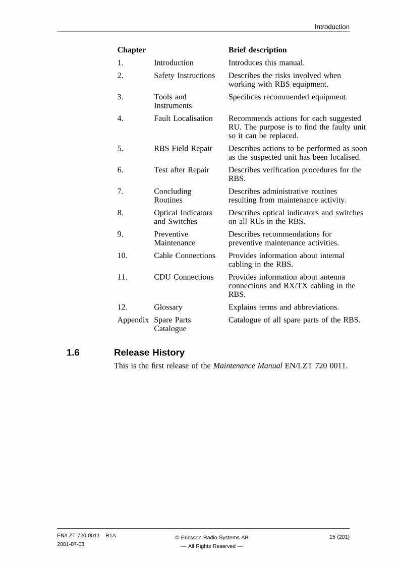
1.5 How to Use this ManualDetailed information about the use of this manual and how to performmaintenance in the correct order, is found in the section MaintenanceProcess Overview in this chapter. A brief description of the contents ofeach chapter of this manual is given below.
14 (201) EN/LZT 720 0011 R1A
2001-07-03© Ericsson Radio Systems AB
— All Rights Reserved —
Introduction
Chapter Brief description
1. Introduction Introduces this manual.
2. Safety Instructions Describes the risks involved whenworking with RBS equipment.
3. Tools andInstruments
Specifices recommended equipment.
4. Fault Localisation Recommends actions for each suggestedRU. The purpose is to find the faulty unitso it can be replaced.
5. RBS Field Repair Describes actions to be performed as soonas the suspected unit has been localised.
6. Test after Repair Describes verification procedures for theRBS.
7. ConcludingRoutines
Describes administrative routinesresulting from maintenance activity.
8. Optical Indicatorsand Switches
Describes optical indicators and switcheson all RUs in the RBS.
9. PreventiveMaintenance
Describes recommendations forpreventive maintenance activities.
10. Cable Connections Provides information about internalcabling in the RBS.
11. CDU Connections Provides information about antennaconnections and RX/TX cabling in theRBS.
12. Glossary Explains terms and abbreviations.
Appendix Spare PartsCatalogue
Catalogue of all spare parts of the RBS.
1.6 Release HistoryThis is the first release of the Maintenance Manual EN/LZT 720 0011.
EN/LZT 720 0011 R1A
2001-07-0315 (201)© Ericsson Radio Systems AB
— All Rights Reserved —

Introduction
This page is intentionally left blank
16 (201) EN/LZT 720 0011 R1A
2001-07-03© Ericsson Radio Systems AB
— All Rights Reserved —
Safety Instructions
2 Safety InstructionsThis chapter shows the system used for presenting safety information.
Note: Reduce the risk of accidents by studying all the instructionscarefully before starting work. If questions arise regardingthe safety instructions, contact the supervisor or the localEricsson company.
Where local regulations exist, these are to be followed. The safetyinformation in this manual is a supplement to local regulations.
It is the responsibility of the local project manager to make certain thatlocal regulations are known and followed.
The relevant manual (including this safety information) and specificinstructions supplied by Ericsson must be followed in any workperformed on the Ericsson products or systems. A sufficient knowledgeof English or of any of the other languages in which the manuals orinstructions are printed is necessary.
The safety information in the relevant manuals presupposes that anyperson performing work on Ericsson products or systems has thenecessary education, training and competence required in order toperform that work correctly. For certain work, additional training orspecial training may be required. For more precise information on theamount and content of the general and/or special training required forwork on Ericsson products or systems, please contact the supervisor orthe local Ericsson company.
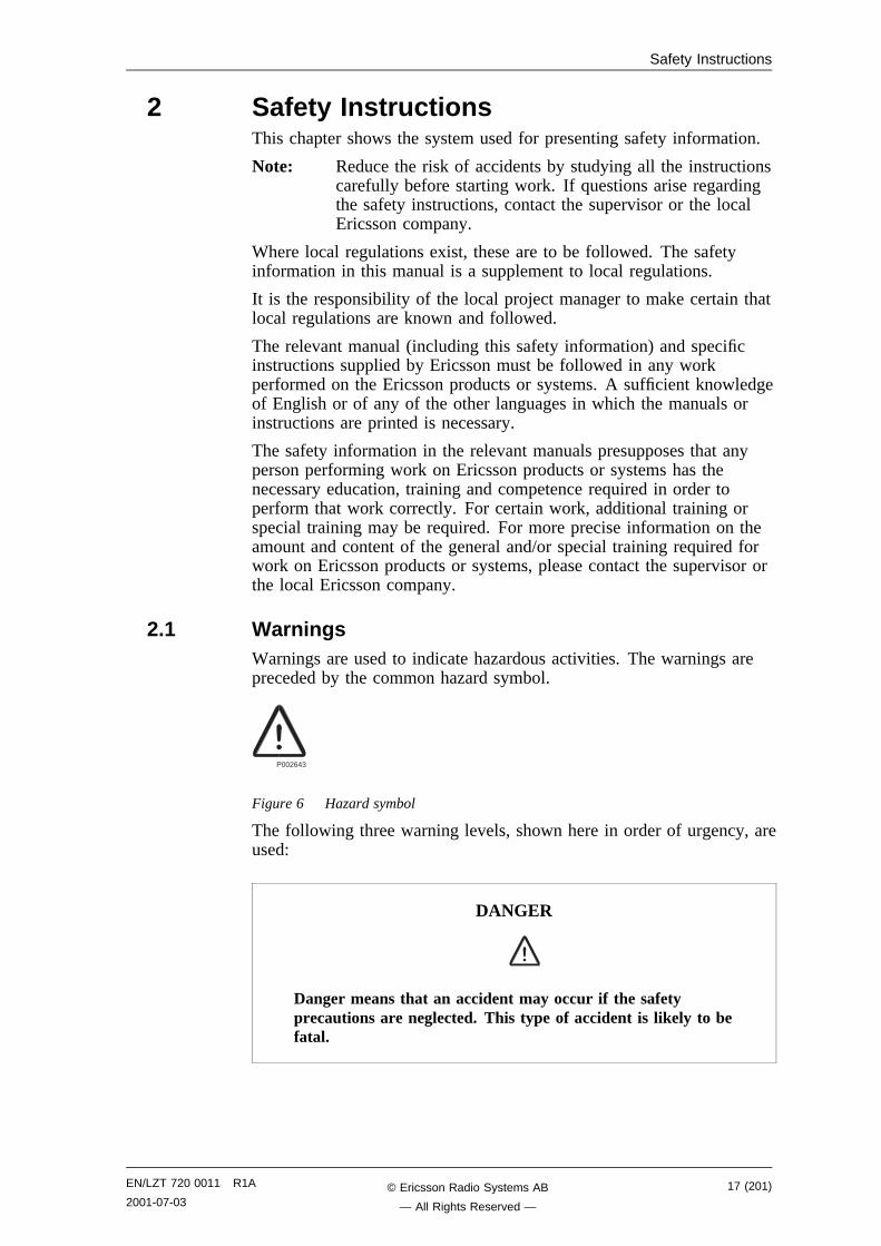
2.1 WarningsWarnings are used to indicate hazardous activities. The warnings arepreceded by the common hazard symbol.
P002643
Figure 6 Hazard symbol
The following three warning levels, shown here in order of urgency, areused:
DANGER
Danger means that an accident may occur if the safetyprecautions are neglected. This type of accident is likely to befatal.
EN/LZT 720 0011 R1A
2001-07-0317 (201)© Ericsson Radio Systems AB
— All Rights Reserved —
Safety Instructions
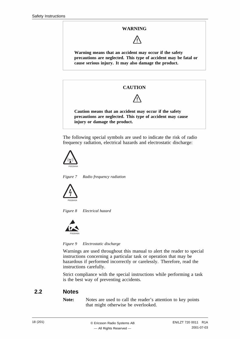
WARNING
Warning means that an accident may occur if the safetyprecautions are neglected. This type of accident may be fatal orcause serious injury. It may also damage the product.
CAUTION
Caution means that an accident may occur if the safetyprecautions are neglected. This type of accident may causeinjury or damage the product.
The following special symbols are used to indicate the risk of radiofrequency radiation, electrical hazards and electrostatic discharge:
P002644A
Figure 7 Radio frequency radiation
���,-�6�
Figure 8 Electrical hazard
���,-�-�
Figure 9 Electrostatic discharge
Warnings are used throughout this manual to alert the reader to specialinstructions concerning a particular task or operation that may behazardous if performed incorrectly or carelessly. Therefore, read theinstructions carefully.
Strict compliance with the special instructions while performing a taskis the best way of preventing accidents.
2.2 NotesNote: Notes are used to call the reader’s attention to key points
that might otherwise be overlooked.
18 (201) EN/LZT 720 0011 R1A
2001-07-03© Ericsson Radio Systems AB
— All Rights Reserved —
Safety Instructions
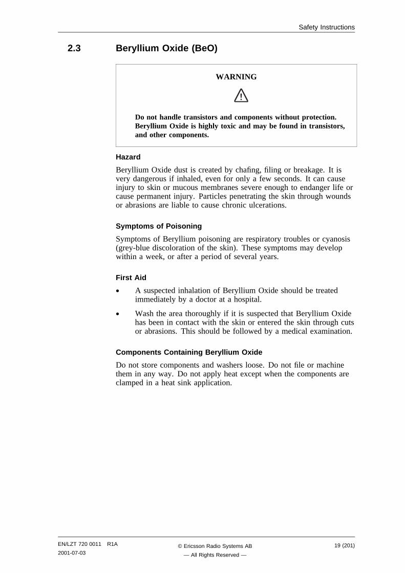
2.3 Beryllium Oxide (BeO)
WARNING
Do not handle transistors and components without protection.Beryllium Oxide is highly toxic and may be found in transistors,and other components.
Hazard
Beryllium Oxide dust is created by chafing, filing or breakage. It isvery dangerous if inhaled, even for only a few seconds. It can causeinjury to skin or mucous membranes severe enough to endanger life orcause permanent injury. Particles penetrating the skin through woundsor abrasions are liable to cause chronic ulcerations.
Symptoms of Poisoning
Symptoms of Beryllium poisoning are respiratory troubles or cyanosis(grey-blue discoloration of the skin). These symptoms may developwithin a week, or after a period of several years.
First Aid
• A suspected inhalation of Beryllium Oxide should be treatedimmediately by a doctor at a hospital.
• Wash the area thoroughly if it is suspected that Beryllium Oxidehas been in contact with the skin or entered the skin through cutsor abrasions. This should be followed by a medical examination.
Components Containing Beryllium Oxide
Do not store components and washers loose. Do not file or machinethem in any way. Do not apply heat except when the components areclamped in a heat sink application.
EN/LZT 720 0011 R1A
2001-07-0319 (201)© Ericsson Radio Systems AB
— All Rights Reserved —
Safety Instructions
Power Transistors, Diodes and Thyristors
WARNING
Do not carry loose components in pockets, bags or containers, ortamper with them in any way that could cause them to break ordisintegrate. Do not apply excessive heat during soldering. Donot break open components for inspection.
Components containing Beryllium Oxide are clearly marked in themanufacturer’s packing, and identified by attached information.
• Store components in their original packing and do not mix themwith other components.
• Ensure that they do not become mechanically damaged. Use carewhen replacing defective components.
• Beryllium Oxide is encapsulated and components are safe tohandle for normal replacement purposes.
Heat Sink Washers
Note: Not all heat sink washers contain Beryllium. Heat sinkscontaining Beryllium, are individually packed when new.
WARNING
Do not store washers loose. Do not file or machine them in anyway. Do not apply heat, except when the components areclamped in a heat sink.
• Handle with gloves or cloth when removing heat sink washersfrom packaging and mounting them into place in the equipment.
20 (201) EN/LZT 720 0011 R1A
2001-07-03© Ericsson Radio Systems AB
— All Rights Reserved —
Safety Instructions
Cathode Ray Tubes (CRTs) and Ceramic Applications
WARNING
Do not handle broken glass with bare fingers. Do not blow onexposed surfaces due to the danger of Beryllium Oxide.
Ceramic cylinders or formers containing Beryllium are marked by bluecolorations or black lines. They are safe to handle provided they are notdamaged. If they are damaged, take precautions as with othercomponents containing Beryllium.
Disposal
Dispose of defective and/or broken Beryllium components in approvedcontainers. Mark them clearly on the outside of the wrapping“COMPONENTS CONTAIN BERYLLIUM”
WARNING
Never send defective and/or broken components containingBeryllium Oxide through the mail. Instead, return them to thenearest depot by hand.
2.4 Electrical Hazards
High Voltage
DANGER
High voltage is used in the operation of this equipment. Bothdirect contact with the mains power and indirect contact viadamp items or moisture can be fatal.
• The AC installation must be carried out according to localregulations. These regulations may require the work to be carriedout by a qualified and authorized electrician.
• Remove wrist watches, rings, bracelets, etc.
• Switch off the power if the cabinet is damp inside.
EN/LZT 720 0011 R1A
2001-07-0321 (201)© Ericsson Radio Systems AB
— All Rights Reserved —
Safety Instructions
• Prevent damp entering the equipment during work in bad weatherconditions.
DANGER
Improper electrical installation may cause fire or electrical shock.Approved circuit breakers for the AC mains and the cable’s crosssectional areas must always be selected in accordance with locallaws and regulations. Only a qualified and authorized electricianis permitted to install or modify the electrical installation.
Cable Markings
CAUTION
Verify that the cable markings correspond before connectingcables.
Faulty Electric Tools
WARNING
Do not repair a faulty electric tool yourself. Hand it over to yoursupervisor in exchange for a functioning tool.
Drilling
WARNING
Do not drill holes in the Radio Base Station. The drill bit maycome into contact with live wires.
• Always use insulated protective gloves, such as the LYB 1032,when drilling where live wires might be hidden.
• Always use eye protectors (goggles) when drilling. Flying chipsand dust may get into your eyes.
22 (201) EN/LZT 720 0011 R1A
2001-07-03© Ericsson Radio Systems AB
— All Rights Reserved —
Safety Instructions
Thunderstorms
DANGER
Avoid working on electrical installations or towers/masts duringthunderstorms.
Thunderstorms create strong electric fields. For that reason, and toavoid direct strokes of lightning, it is essential that the equipment isproperly earthed for thunderstorm conditions.
2.4.1 Electrostatic Discharge, ESD
CAUTION
Sensitive components such as Integrated Circuits (IC) can bedamaged by discharges of static electricity.
Electrical charges are generated by friction when a body moves, rubsagainst clothes, slides against a chair, when shoes rub against the floor,and when you handle ordinary plastics, etc. Such charges may remainfor a considerable period of time.
Handling of printed board assemblies and IC components
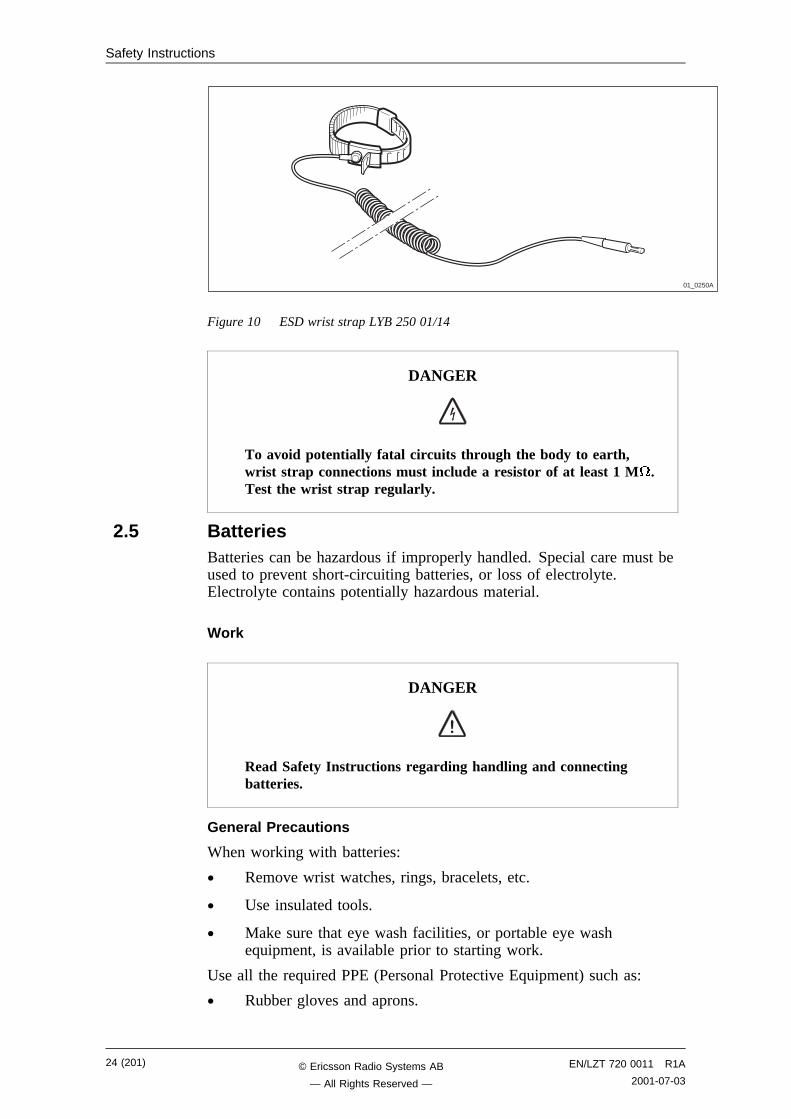
Always use an approved antistatic bracelet to avoid damage tocomponents mounted on printed board assemblies. The ESD wrist strapcontains a resistor with an ohmic value greater than 1 M in the cableto protect the operator. The resistance value is low enough to dischargethe electrostatic voltage. Never replace the cable with any other cable.The ESD wrist strap must be connected to earth. Ericsson recommendswrist strap LYB 250 01/14.
Storing and Transporting printed board assemblies and IC Components
Use the original packaging. If this is not available, use a conductivematerial, or a special IC carrier that either short-circuits or insulates allleads of the components.
EN/LZT 720 0011 R1A
2001-07-0323 (201)© Ericsson Radio Systems AB
— All Rights Reserved —
Safety Instructions
01_0250A
Figure 10 ESD wrist strap LYB 250 01/14
DANGER
To avoid potentially fatal circuits through the body to earth,wrist strap connections must include a resistor of at least 1 M .Test the wrist strap regularly.
2.5 BatteriesBatteries can be hazardous if improperly handled. Special care must beused to prevent short-circuiting batteries, or loss of electrolyte.Electrolyte contains potentially hazardous material.
Work
DANGER
Read Safety Instructions regarding handling and connectingbatteries.
General Precautions
When working with batteries:
• Remove wrist watches, rings, bracelets, etc.
• Use insulated tools.
• Make sure that eye wash facilities, or portable eye washequipment, is available prior to starting work.
Use all the required PPE (Personal Protective Equipment) such as:
• Rubber gloves and aprons.
24 (201) EN/LZT 720 0011 R1A
2001-07-03© Ericsson Radio Systems AB
— All Rights Reserved —
Safety Instructions
• Eye protection (goggles or a face shield).
Short-Circuiting of Batteries
CAUTION
Short circuits can cause injury or damage. Although the batteryvoltage may be low, the released power can be extremely high.
It is necessary to ensure that no metal object, such as a tool, short-circuits the batteries. If necessary, disconnect or remove the batteriesbefore beginning work.
Explosive Gases
Batteries may give off explosive gases. All battery areas must beadequately ventilated and protected from fire.
CAUTION
Do not use open cell-lead acid batteries. They give off hazardousgases that may cause an explosion or corrosion of the equipment.The battery must be suitable for horizontal operation.
Overheated Batteries
CAUTION
Excessive heat can cause the battery casings to become soft andto warp, allowing acid to escape.
If the internal temperature of the cabinet exceeds + 60 C (140 F), takethe following precautions:
• Check that the batteries have not leaked.
• If the batteries have leaked, see the section Hazardous WasteMaterial from Leaks.
EN/LZT 720 0011 R1A
2001-07-0325 (201)© Ericsson Radio Systems AB
— All Rights Reserved —
Safety Instructions
Hazardous Waste Material from Leaks
Ensure that there are sufficient absorbers or neutralizing materialsavailable on site, in case of spillage of hazardous substances. There is adanger of spillage occurring when installing, removing, replacing orservicing batteries. The absorbers and neutralizing materials must besuitable for the hazardous substances involved.
Table 1 Typical Neutralizers
Typical neutralisers
Baking soda (bicarbonate) NaHCO3
Sal soda Na2CO3IOH2O
Soda ash Na2CO3
Consult the battery manufacturers for specific details of absorbers andneutralizing materials. Absorbers and neutralizing products will vary,depending on country and manufacturer.
2.6 Working at Heights
WARNING
Some working areas involve the risk of accidents caused byfalling objects.
For example, when working on a mast, tower or a roof, the followingprecautions must be taken:
• Personnel working at heights must have the appropriate trainingand medical certificate.
• Full body safety harness and safety helmet must be used.
• Adequate protective clothing is essential in cold weather.
• All lifting devices must be tested and approved.
• During work on a mast, all personnel in the area must wearhelmets.
2.6.1 Rules and Advice for the Safe Use of Ladders
• Make sure that the ladder is undamaged and has been approvedfor use.
• Do not overload the ladder.
The following types of ladders must be guyed or otherwise secured
• Leaning ladder longer than 5m.
26 (201) EN/LZT 720 0011 R1A
2001-07-03© Ericsson Radio Systems AB
— All Rights Reserved —
Safety Instructions
• Free-standing ladder with a platform and knee-support, and withover 2 meters height to the platform.
• Any other free-standing ladder longer than 3m.
Positioning the ladder
02_0354A
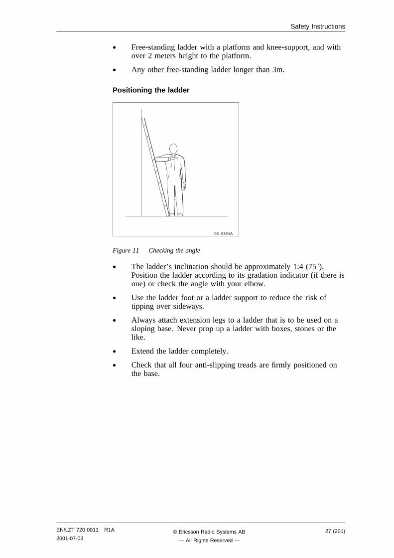
Figure 11 Checking the angle
• The ladder’s inclination should be approximately 1:4 (75 ).Position the ladder according to its gradation indicator (if there isone) or check the angle with your elbow.
• Use the ladder foot or a ladder support to reduce the risk oftipping over sideways.
• Always attach extension legs to a ladder that is to be used on asloping base. Never prop up a ladder with boxes, stones or thelike.
• Extend the ladder completely.
• Check that all four anti-slipping treads are firmly positioned onthe base.
EN/LZT 720 0011 R1A
2001-07-0327 (201)© Ericsson Radio Systems AB
— All Rights Reserved —
Safety Instructions
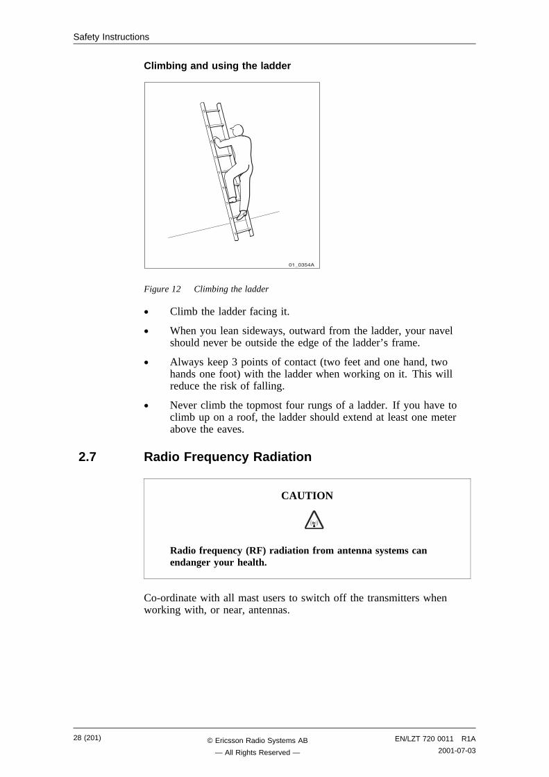
Climbing and using the ladder
01_0354A
Figure 12 Climbing the ladder
• Climb the ladder facing it.
• When you lean sideways, outward from the ladder, your navelshould never be outside the edge of the ladder’s frame.
• Always keep 3 points of contact (two feet and one hand, twohands one foot) with the ladder when working on it. This willreduce the risk of falling.
• Never climb the topmost four rungs of a ladder. If you have toclimb up on a roof, the ladder should extend at least one meterabove the eaves.
2.7 Radio Frequency Radiation
CAUTION
Radio frequency (RF) radiation from antenna systems canendanger your health.
Co-ordinate with all mast users to switch off the transmitters whenworking with, or near, antennas.
28 (201) EN/LZT 720 0011 R1A
2001-07-03© Ericsson Radio Systems AB
— All Rights Reserved —
Safety Instructions
2.8 Other Hazards
Handling Heavy Goods
WARNING
Read the Safety chapter regarding handling of heavy goods.
• Use tested and approved lifting devices only. They must only beused by trained personnel.
• Always check that all parts of the lifting devices are intact.
• Make sure that all lifting devices are properly stabilised orattached to fixed objects such as walls or buildings before lifting.
• Give clear and consistent command signals, for example
− lift
− lower
− stop
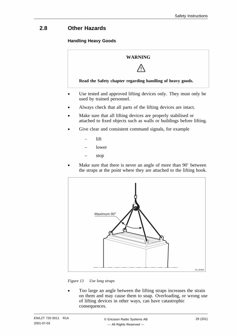
• Make sure that there is never an angle of more than 90 betweenthe straps at the point where they are attached to the lifting hook.
04_0030A
Maximum 90°
Figure 13 Use long straps
• Too large an angle between the lifting straps increases the strainon them and may cause them to snap. Overloading, or wrong useof lifting devices in other ways, can have catastrophicconsequences.
EN/LZT 720 0011 R1A
2001-07-0329 (201)© Ericsson Radio Systems AB
— All Rights Reserved —
Safety Instructions
• Never walk under hoisted loads.
• Follow local regulations for safety clothing and safety equipmentfor hoisting and moving goods.
• Unsecured cabinets have a high centre of gravity. They can easilytip over and harm personnel.
WARNING
There is a danger of the assembly toppling over, which couldcause injury to personnel or damage to the equipment.
Fire
WARNING
Fire may spread to neighbouring rooms. When working on aradio base station you may have to open cable ducts, channelsand access holes, thereby interfering with the fire sectioning ofthe building.
• Close the cable ducts and fire doors (if applicable) as soon aspossible.
• After completing work on cables, seal the cable ducts accordingto the regulations for the building.
• Minimize the amount of inflammable material.
• Avoid storing empty packaging material on the site.
• Use a powder or carbon dioxide type of fire extinguisher due tothe electric nature of the equipment inside the Radio Base Station.
Sharp Edges
WARNING
Wear protective gloves when handling the equipment. Theremay be sharp metal edges.
30 (201) EN/LZT 720 0011 R1A
2001-07-03© Ericsson Radio Systems AB
— All Rights Reserved —
Tools and Instruments
3 Tools and InstrumentsThis chapter describes tools and instruments required for maintenanceactivities.
3.1 Test EquipmentTable 2 Test equipment
Product No. Description Specification / Remark
FAB 801 0187 TEMS SW TEMS
TEMS cable
User’s manual
TEMS R320 for both 900
and 1800 MHz (Dual Band)
Antenna adapter
Click-in-holder, Car kit
FAB 801 0194 TEMS SW TEMS
TEMS cable
User’s manual
TEMS T28 World for both
900 and 1900 MHz
Antenna adapter
Click-in-holder, Car kit
LPK 102 024/2 Digital multimeter Fluke 79 III
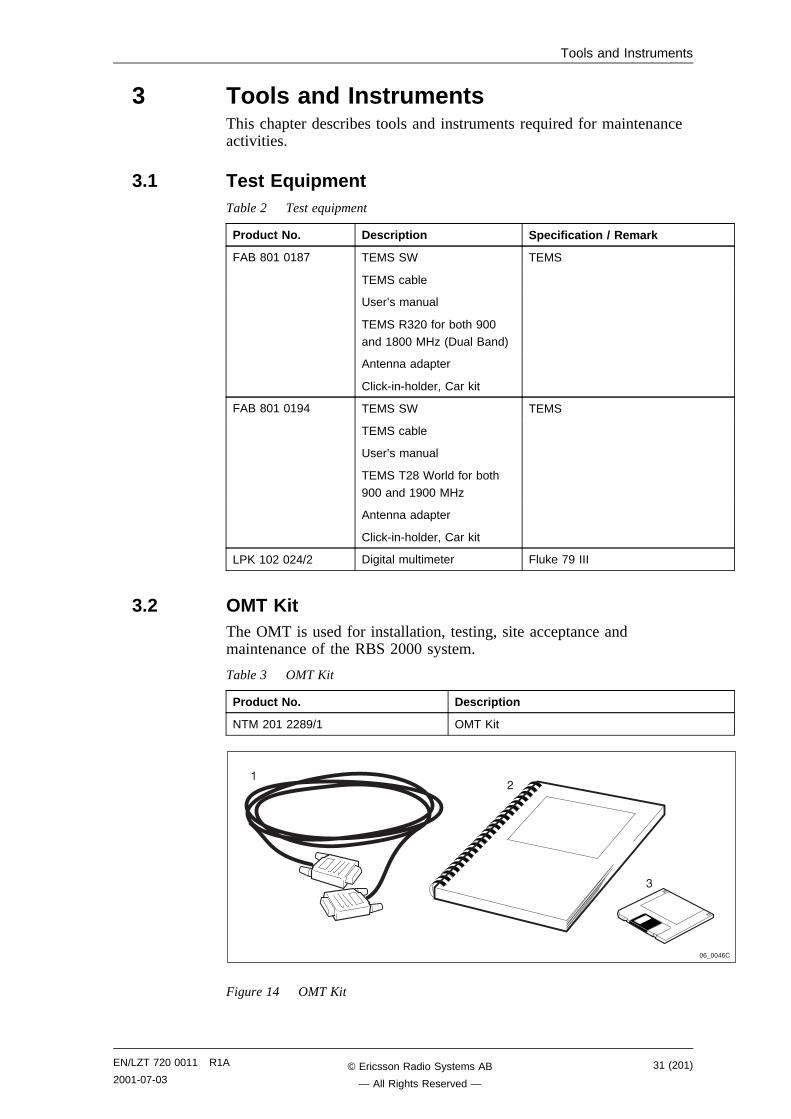
3.2 OMT KitThe OMT is used for installation, testing, site acceptance andmaintenance of the RBS 2000 system.
Table 3 OMT Kit
Product No. Description
NTM 201 2289/1 OMT Kit
�-7���-�
,
"
�
Figure 14 OMT Kit
EN/LZT 720 0011 R1A
2001-07-0331 (201)© Ericsson Radio Systems AB
— All Rights Reserved —
Tools and Instruments
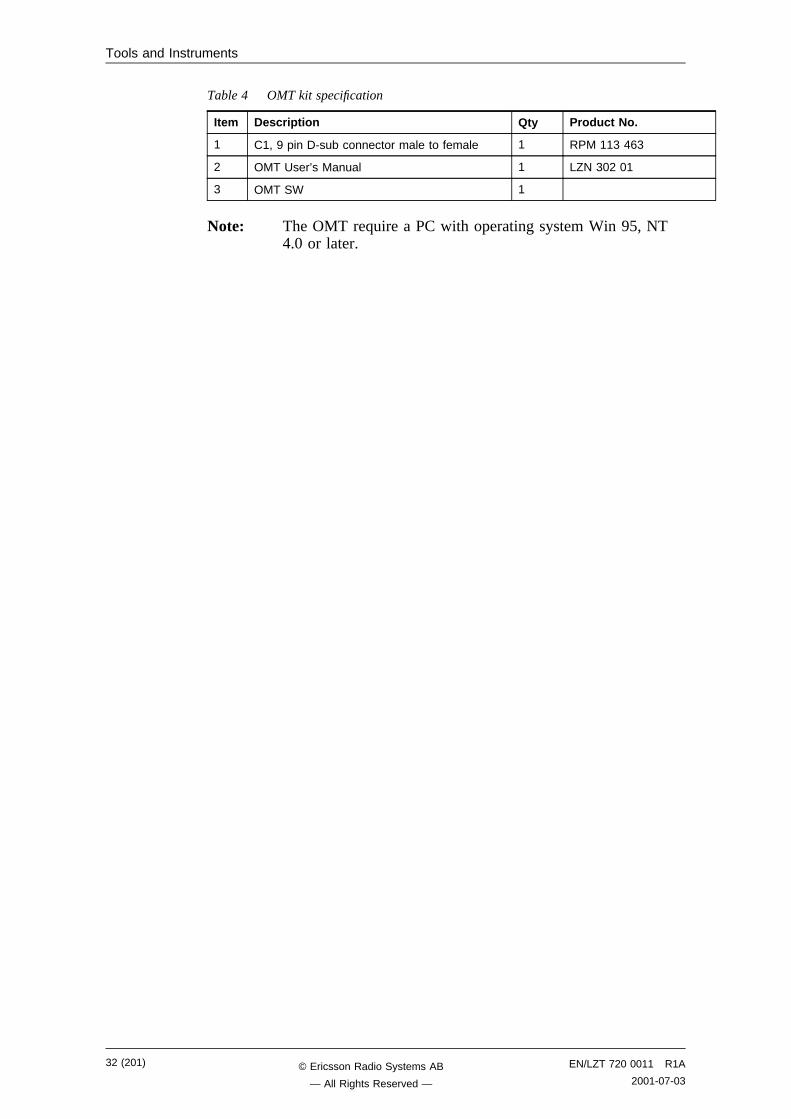
Table 4 OMT kit specification
Item Description Qty Product No.
1 C1, 9 pin D-sub connector male to female 1 RPM 113 463
2 OMT User’s Manual 1 LZN 302 01
3 OMT SW 1
Note: The OMT require a PC with operating system Win 95, NT4.0 or later.
32 (201) EN/LZT 720 0011 R1A
2001-07-03© Ericsson Radio Systems AB
— All Rights Reserved —
Tools and Instruments
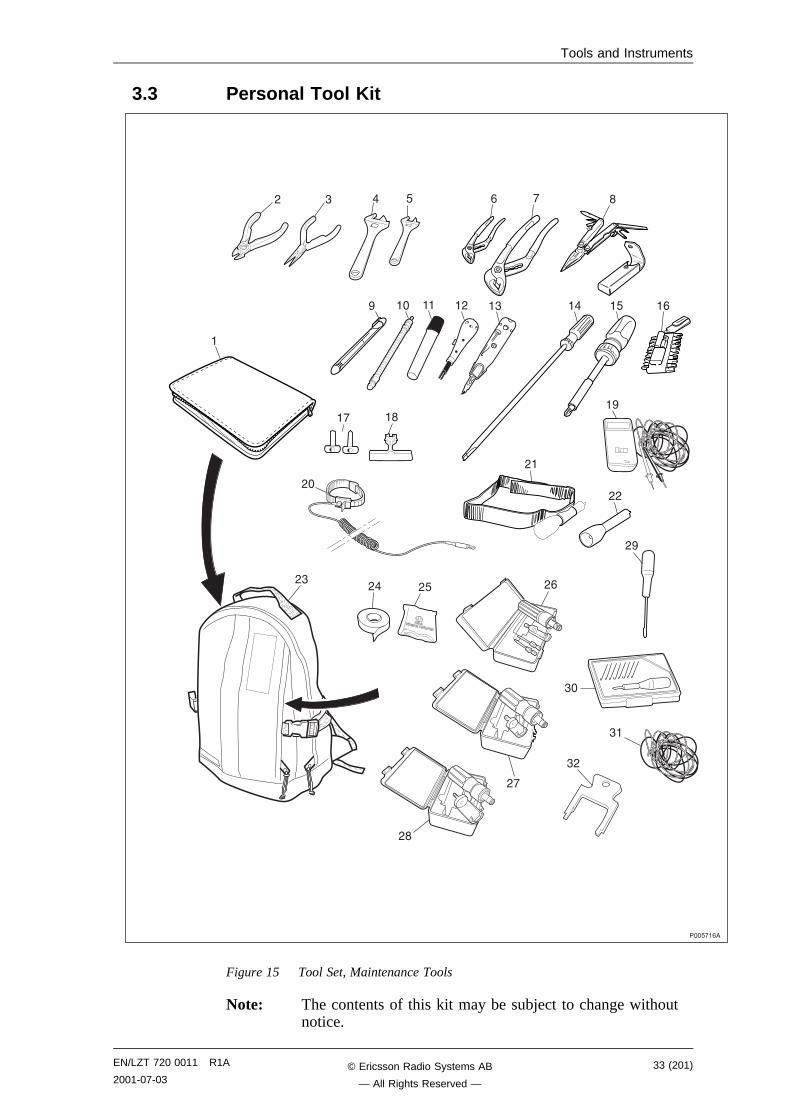
3.3 Personal Tool Kit
���6!�-�
, " � 6 - ! �
� �� �� �, �" �� �6
�! ��
,�
,"
�
,� ,6
,�
,,
��
,�
,-
",
"�
"�
,!
,�
�-
Figure 15 Tool Set, Maintenance Tools
Note: The contents of this kit may be subject to change withoutnotice.
EN/LZT 720 0011 R1A
2001-07-0333 (201)© Ericsson Radio Systems AB
— All Rights Reserved —
Tools and Instruments
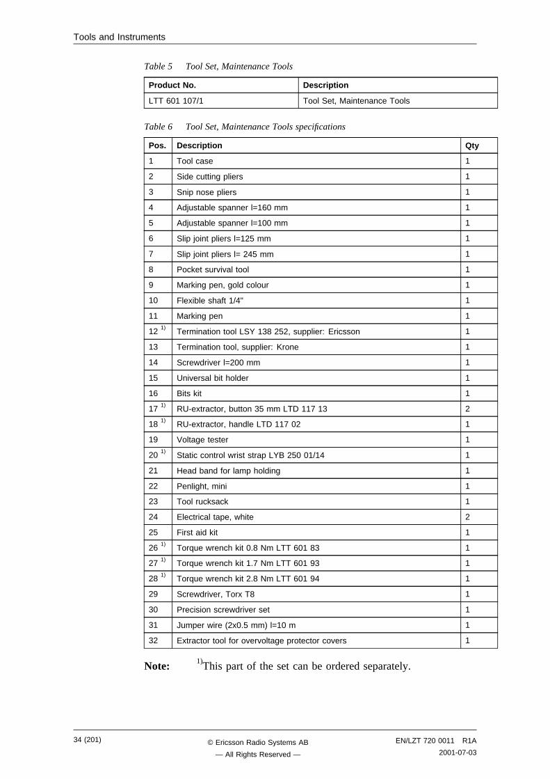
Table 5 Tool Set, Maintenance Tools
Product No. Description
LTT 601 107/1 Tool Set, Maintenance Tools
Table 6 Tool Set, Maintenance Tools specifications
Pos. Description Qty
1 Tool case 1
2 Side cutting pliers 1
3 Snip nose pliers 1
4 Adjustable spanner l=160 mm 1
5 Adjustable spanner l=100 mm 1
6 Slip joint pliers l=125 mm 1
7 Slip joint pliers l= 245 mm 1
8 Pocket survival tool 1
9 Marking pen, gold colour 1
10 Flexible shaft 1/4" 1
11 Marking pen 1
12 1)Termination tool LSY 138 252, supplier: Ericsson 1
13 Termination tool, supplier: Krone 1
14 Screwdriver l=200 mm 1
15 Universal bit holder 1
16 Bits kit 1
17 1) RU-extractor, button 35 mm LTD 117 13 2
18 1) RU-extractor, handle LTD 117 02 1
19 Voltage tester 1
20 1)Static control wrist strap LYB 250 01/14 1
21 Head band for lamp holding 1
22 Penlight, mini 1
23 Tool rucksack 1
24 Electrical tape, white 2
25 First aid kit 1
26 1) Torque wrench kit 0.8 Nm LTT 601 83 1
27 1) Torque wrench kit 1.7 Nm LTT 601 93 1
28 1) Torque wrench kit 2.8 Nm LTT 601 94 1
29 Screwdriver, Torx T8 1
30 Precision screwdriver set 1
31 Jumper wire (2x0.5 mm) l=10 m 1
32 Extractor tool for overvoltage protector covers 1
Note: 1)This part of the set can be ordered separately.
34 (201) EN/LZT 720 0011 R1A
2001-07-03© Ericsson Radio Systems AB
— All Rights Reserved —
Tools and Instruments
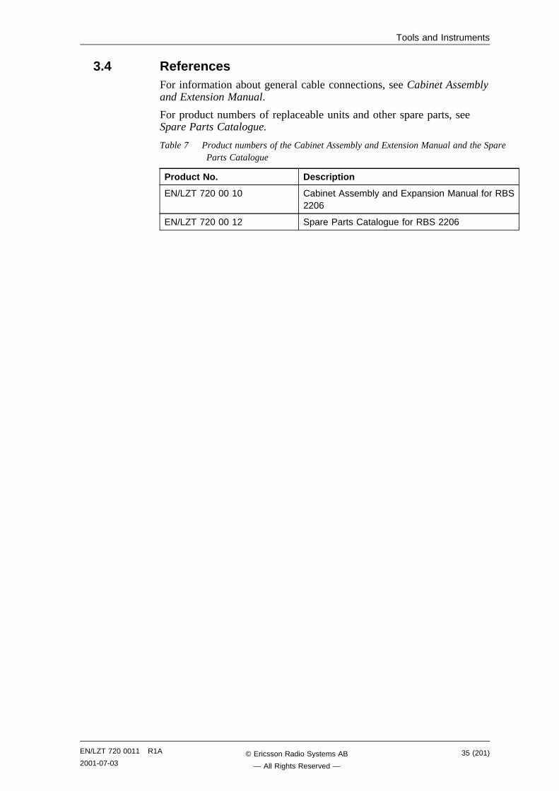
3.4 ReferencesFor information about general cable connections, see Cabinet Assemblyand Extension Manual.
For product numbers of replaceable units and other spare parts, seeSpare Parts Catalogue.
Table 7 Product numbers of the Cabinet Assembly and Extension Manual and the SpareParts Catalogue
Product No. Description
EN/LZT 720 00 10 Cabinet Assembly and Expansion Manual for RBS2206
EN/LZT 720 00 12 Spare Parts Catalogue for RBS 2206
EN/LZT 720 0011 R1A
2001-07-0335 (201)© Ericsson Radio Systems AB
— All Rights Reserved —

Tools and Instruments
This page is intentionally left blank
36 (201) EN/LZT 720 0011 R1A
2001-07-03© Ericsson Radio Systems AB
— All Rights Reserved —
Fault Localisation
4 Fault Localisation
4.1 IntroductionThe instructions in this chapter describe to handle fault situations thatarise in the RBS.
The flowcharts in this chapter are for reference only. The textaccompanying each flowchart contains more detailed instructions.Maintenance personnel should therefore only use the charts to locate theinformation in the text.
All subsequent sections provide instructions on how to localise faults inthe RBS. Each title of a section corresponds to a fault code in either theSO CF RU map or the SO TRXC RU map. These sections appear inalphabetical order.
4.1.1 Preconditions
Information from the replacement unit map is required as input whenreading this chapter.
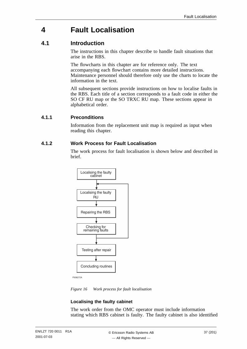
4.1.2 Work Process for Fault Localisation
The work process for fault localisation is shown below and described inbrief.
����,!,�
.� ����$��&���#��% (���
�����$��������+��
��+���$��&�����
�&� 3�$���������$��#���
�� �#��$���#����
.� ����$��&���#��%�
Figure 16 Work process for fault localisation
Localising the faulty cabinet
The work order from the OMC operator must include informationstating which RBS cabinet is faulty. The faulty cabinet is also identified
EN/LZT 720 0011 R1A
2001-07-0337 (201)© Ericsson Radio Systems AB
— All Rights Reserved —
Fault Localisation
by the yellow RBS fault indicator, which is on when there is a fault.The RBS fault indicator is located at the left edge of the cabinet door.
Localising the faulty RU
The work order from the OMC operator also includes informationstating which RU is faulty. The sections below describe the faultlocalisation processes relating to each faulty RU that is indicated in thefault lists. See Section 4.2 on page 38. Most RUs are equipped with ared Fault indicator. This indicator is on if a fault has been detected inthe RU. RUs that do not have a Fault indicator, can, if faulty, only belocalised by means of the OMT.
Note: Always check for a released circuit breaker on the IDM,where applicable. The very first action must always be toreset a circuit breaker, that has released. If the circuitbreaker releases again, the fault localisation procedure shallcontinue. See chapter Optical Indicators and Switches forthe positions of all circuit breakers on the IDM.
Repairing the RBS
When the faulty RU has been identified, it shall be handled according tospecified procedures. See chapter RBS Field Repair.
Checking for remaining faults
When the faulty RU is replaced and the reported fault has ceased, thefield technician has to check that there are no faults remaining in theRBS.
If any faults remain in the RBS, these faults have to be localised andrectified. See the sections below in this chapter.
Testing after repair
When all faults in the RBS have been cleared, the RBS has to be testedin order to verify that it is fully functional. See chapter Test afterRepair.
Concluding routines
Before leaving the site, the field technician has to go through a checklistand fill in the repair delivery note, “Blue tag”. The routines also definehow the faulty, replaced RUs shall be treated. See chapter ConcludingRoutines.
4.2 Fault ListsThe tables below give all faults that are treated in this chapter. Thesefaults are indicating that a fault is found in HW.
Note: Faults that can not be related to the RBS 2206 are excluded.
38 (201) EN/LZT 720 0011 R1A
2001-07-03© Ericsson Radio Systems AB
— All Rights Reserved —
Fault Localisation
4.2.1 Faults in the SO CF RU map
FaultNo.
Fault designation
0 DXU
3 Y link
5 CDU
7 PSU
9 BDM or BFU
12 ALNA/TMA A
13 ALNA/TMA B
14 Battery
15 Fan
20 TMA CM
23 CDU RX in cable
30 CDU bus/IOM bus
31 Environment
33 EPC bus/Power communication loop
34 RBS DB
35 EOM bus
37 CDU CXU RXA cable
38 CDU CXU RXB cable
40 Antenna
41 PSU DC cable
43 Flash card
45 Battery temp sensor
46 FCU
47 TMA CM cable
4.2.2 Faults in the SO TRXC RU map
FaultNo.
Fault designation
0 TRU, dTRU or ATRU
3 CXU TRU RXA cable
4 CXU TRU RXB cable
EN/LZT 720 0011 R1A
2001-07-0339 (201)© Ericsson Radio Systems AB
— All Rights Reserved —
Fault Localisation
4.2.3 All HW faults in alphabetical order
Fault designation Fault No.
ALNA/TMA A SO CF RU:12
ALNA/TMA B SO CF RU:13
Antenna SO CF RU:40
Battery SO CF RU:14
Battery temp sensor SO CF RU:45
BDM or BFU SO CF RU:9
CDU SO CF RU:5
CDU bus/IOM bus SO CF RU:30
CDU CXU RXA cable SO CF RU:37
CDU CXU RXB cable SO CF RU:38
CDU RX in cable SO CF RU:23
CXU TRU RXA cable SO TRXC RU:3
CXU TRU RXB cable SO TRXC RU:4
DXU SO CF RU:0
Environment SO CF RU:31
EOM bus SO CF RU:35
EPC bus/Power communication loop SO CF RU:33
Fan SO CF RU:15
FCU SO CF RU:46
Flash card SO CF RU:43
PSU SO CF RU:7
PSU DC cable SO CF RU:41
RBS DB SO CF RU:34
TMA CM SO CF RU:20
TMA CM cable SO CF RU:47
TRU, dTRU or ATRU SO TRXC RU:0
Y link SO CF RU:3
4.3 ALNA/TMA A and ALNA/TMA BNote: This section will be included in the next release.
40 (201) EN/LZT 720 0011 R1A
2001-07-03© Ericsson Radio Systems AB
— All Rights Reserved —
Fault Localisation
4.4 Antenna
����,!��
�-������������+��
�!.� ����������$
�#���
����� ���#+��0����
8�
8�
����
����+�%��#����������
,�%+������#��9
:��
�����0�����%�����
���+
!���������%
�� 9
6.� ����� ��� �
-��+� ����
����������
��&� 3��� �
��#��%��� �
��#�9
����+� ����
����������
��.� ����� ��� �
���+� ���#��%
#*����%��;#�+���
".� ����� ��� �
�,�����#�� �����9
�"��+� ����
8�
�������#�� �����9
:��
�6�����#��
��� �������9
:��
8�
�#*����%�;#�+���
�#��1�&���#��
:��
:��
8�
Figure 17 Antenna fault
EN/LZT 720 0011 R1A
2001-07-0341 (201)© Ericsson Radio Systems AB
— All Rights Reserved —
Fault Localisation
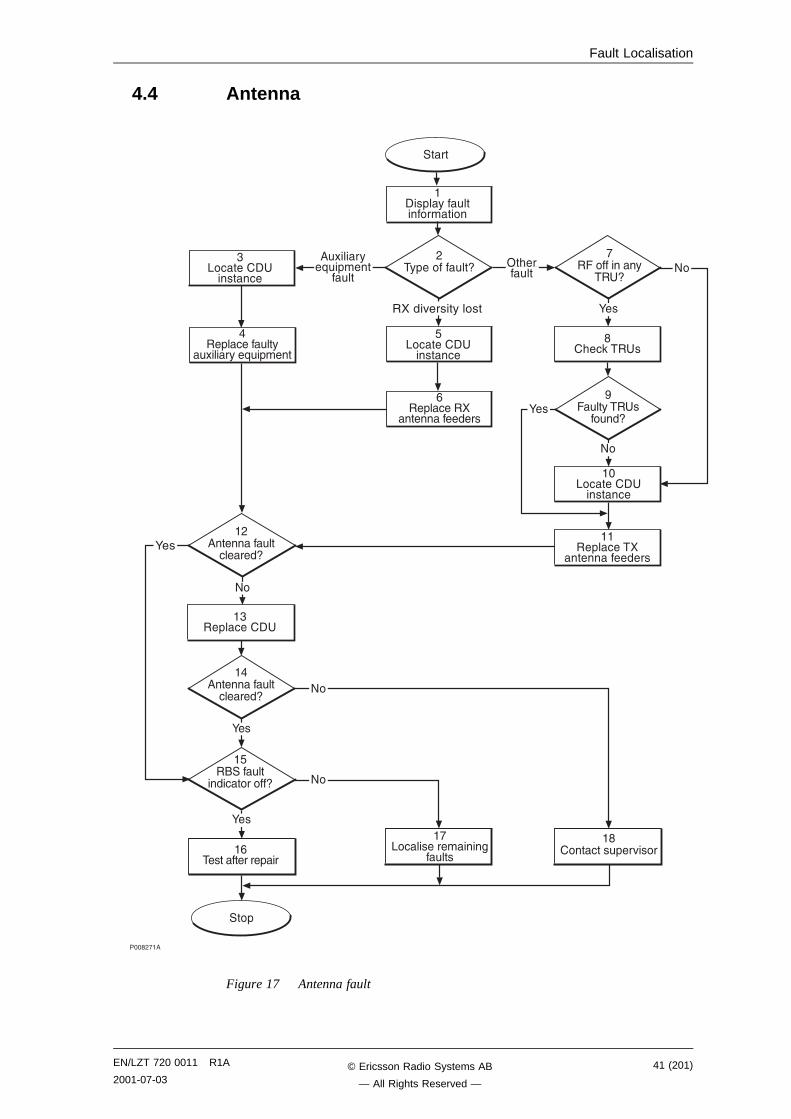
(1) Display fault information
1. Use the monitor Display Faulty RUs in the OMT to list all RUsthat are faulty.
2. Display the type of fault: Go to the Operation menu and selectMonitor . In the RBS Monitor Setup window, select FaultStatus and click the Start Monitor button.
(2) Type of fault?
1. Check the Start Monitor in the OMT as described above in stage(1).
Which type of fault was found in stage (1)?
Answer Action
Auxilliary Equipment fault. Proceed to stage (3)
RX diversity lost. Proceed to stage (5)
Other fault. Proceed to stage (7)
(3) Locate CDU instance
1. Select Hardware view in the OMT.
2. Tick the Faults check box.
3. Look for a red line between a CDU object and an antenna object.
4. When the faulty antenna instance is found, check which CDU it isconnected to. This information indicates which auxilliaryequipment to replace in stage (4).
(4) Replace faulty auxilliary equipment
1. Replace or repair the faulty auxilliary equipment.
2. Proceed to stage (12).
(5) Locate CDU instance
1. Select Hardware view in the OMT.
2. Tick the Faults check box.
3. Look for a red line between a CDU object and an antenna object.
4. When the faulty antenna instance is found, check which CDU it isconnected to. This information indicates which RX antenna feederto replace in stage (6).
(6) Replace RX antenna feeders
1. Replace the RXA or RXB feeder according to instructions insection RX Antenna Feeder in chapter RBS Field Repair.
2. Proceed to stage (12).
42 (201) EN/LZT 720 0011 R1A
2001-07-03© Ericsson Radio Systems AB
— All Rights Reserved —
Fault Localisation
(7) RF off in any TRU?
1. Check all TRUs in the cabinet.
Are any of the RF off indicators on?
Answer Comment Action
Yes One or more RF off indicators are on Proceed to stage (8)
No No RF off indicator is on Proceed to stage (10)
(8) Check TRUs
1. In the OMT, select System view and the object RBS 2000. Go tothe Operation menu and select Monitor.
2. In the RBS Monitor Setup window, select Fault Status and clickthe Start Monitor button.
3. Look for the alarm TX antenna VSWR limits exceeded in theAOTX map. This will point to the TRU(s) generating the alarm.Note that the indicated TRU(s) should match those indicated instage (7) above.
(9) Faulty TRUs found?
1. Check the red Fault and the green Operational indicators on theCDU.
Could the faulty TRUs be found by the OMT?
Answer Comment Action
Yes One or more faulty TRUs could befound.
Proceed to stage (11)
No No faulty TRU could be found. Proceed to stage (10)
(10) Locate CDU instance
1. Select Hardware view in the OMT.
2. Tick the Faults check box.
3. Look for a red line between a CDU object and an antenna object.
4. When the faulty antenna instance is found, check which CDU it isconnected to. This information indicates which TX antenna feederto replace in stage (11).
(11) Replace the TX antenna feeders
1. Replace all the TX feeders in the cell according to instructions insection TX Antenna Feeder in chapter RBS Field Repair.
(12) Antenna fault cleared?
1. Use the OMT to display the type of fault: Go to the Operationmenu and select Monitor.
EN/LZT 720 0011 R1A
2001-07-0343 (201)© Ericsson Radio Systems AB
— All Rights Reserved —
Fault Localisation
2. In the RBS Monitor Setup window, select Fault Status and clickthe Start Monitor button.
• If the fault was "RX Diversity Lost", it will take at least 1 h40 min for the fault in the RBS to cease.
• If the fault was "VSWR Limits Exceeded", the TX has to bere-initiated from the BSC.
For further information, see section RX and TX Antenna Feeder inchapter RBS Field Repair.
3. Has the antenna found to be OK in step (2) above?
Answer Comment Action
Yes The Antenna fault is cleared. Proceed to stage (15)
No There is still an Antenna fault. Proceed to stage (13)
(13) Replace CDU
1. Replace the CDU according to instructions in section CDU inchapter RBS Field Repair.
(14) Antenna fault cleared?
1. Use the OMT to display the type of fault: Go to the Operationmenu and select Monitor.
2. In the RBS Monitor Setup window, select Fault Status and clickthe Start Monitor button.
• If the fault was "RX Diversity Lost", it will take at least 1 h40 min for the fault in the RBS to cease.
• If the fault was "VSWR Limits Exceeded", the TX has to bere-initiated from the BSC.
For further information, see section RX and TX Antenna Feeder inchapter RBS Field Repair.
3. Has the antenna found to be OK in step (2) above?
Answer Comment Action
Yes The Antenna fault is cleared. Proceed to stage (15)
No There is still an Antenna fault. Proceed to stage (18)
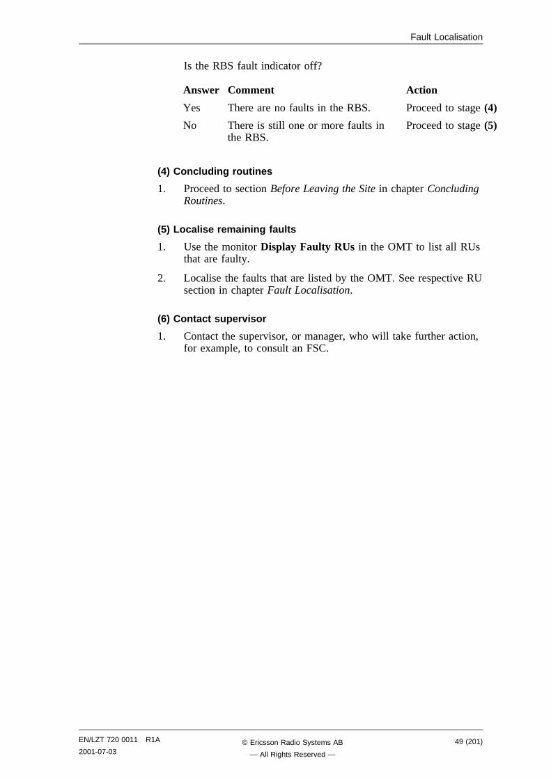
(15) RBS fault indicator off?
1. Check that there are no faults remaining in the RBS. The yellowRBS fault indicator is located on the RBS Status Panel as well ason the DXU.
Is the RBS fault indicator off?
44 (201) EN/LZT 720 0011 R1A
2001-07-03© Ericsson Radio Systems AB
— All Rights Reserved —
Fault Localisation
Answer Comment Action
Yes There are no faults in the RBS. Proceed to stage (16)
No There is still one or more faults inthe RBS.
Proceed to stage (17)
(16) Test after repair
1. (After replacing a CDU only) Make a test call according tosection Test Call in chapter Test after Repair.
2. Proceed to section Before Leaving the Site in chapter ConcludingRoutines.
(17) Localise remaining faults
1. Use the monitor Display Faulty RUs in the OMT to list all RUsthat are faulty.
2. Localise the faults that are listed by the OMT. See respective RUsection in chapter Fault Localisation.
(18) Contact supervisor
1. Contact the supervisor, or manager, who will take further action,for example, to consult an FSC.
4.5 BatteryThe Battery fault only arises when the external battery back-up system,specifically BBS 2000, is connected to the RBS.
EN/LZT 720 0011 R1A
2001-07-0345 (201)© Ericsson Radio Systems AB
— All Rights Reserved —
Fault Localisation
�����"��
�.� ������#����
�*�����(����%��%����
����
���+
��� �#��$���#����
,�����%��#�� �����9
"�����#��
��� �������9
:��
6.� ����������$��#���
-��� ���#+��0����
:��
8�
8�
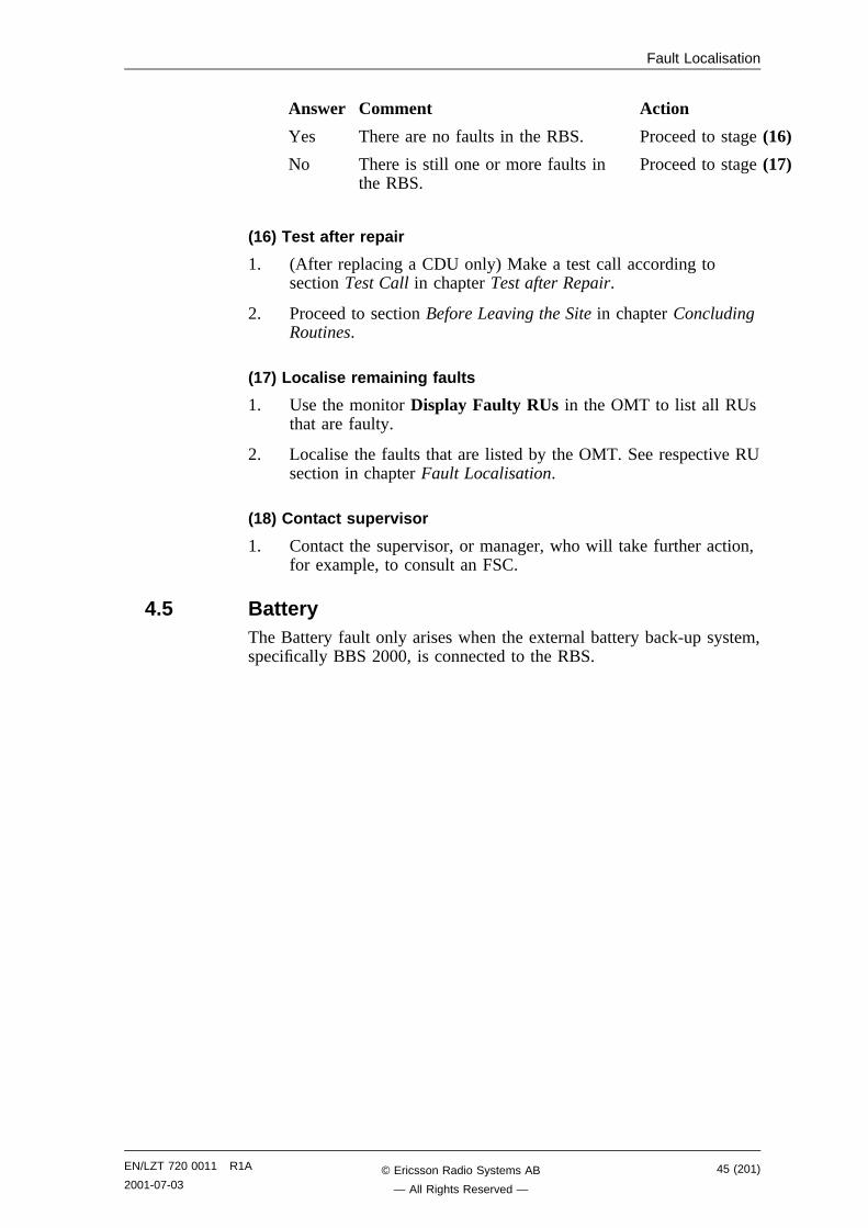
Figure 18 Battery fault, external batteries
(1) Localise fault on external battery system
1. Check that the battery cable is properly connected to the RBS.
2. Check the battery cable from the external battery system to theRBS. Replace if needed.
3. Refer to manufacturer’s documentation to perform faultlocalisation on the external battery system.
(2) Battery fault cleared?
1. Use the monitor Display Faulty RUs in the OMT to list all RUsthat are faulty.
Has the Battery fault disappeared?
Answer Comment Action
Yes The Battery fault is cleared. Proceed to stage (3)
No There is still a Battery fault. Proceed to stage (6)
(3) RBS fault indicator off?
1. Check that there are no faults remaining in the RBS. The yellowRBS fault indicator is located on the RBS Status Panel as well ason the DXU.
46 (201) EN/LZT 720 0011 R1A
2001-07-03© Ericsson Radio Systems AB
— All Rights Reserved —
Fault Localisation
Is the RBS fault indicator off?
Answer Comment Action
Yes There are no faults in the RBS. Proceed to stage (4)
No There is still one or more faults in theRBS.
Proceed to stage (5)
(4) Concluding routines
1. Proceed to section Before Leaving the Site in chapter ConcludingRoutines.
(5) Localise remaining faults
1. Use the monitor Display Faulty RUs in the OMT to list all RUsthat are faulty.
2. Localise the faults that are listed by the OMT. See respective RUsection in chapter Fault Localisation.
(6) Contact supervisor
1. Contact the supervisor, or manager, who will take further action,for example, to consult an FSC.
4.6 Battery Temp SensorNote: This section will be included in the next release.
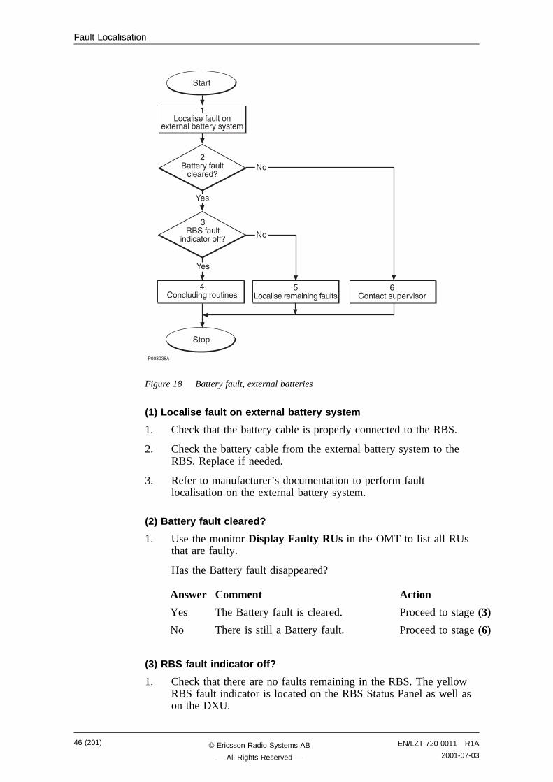
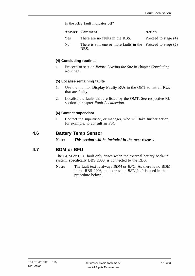
4.7 BDM or BFUThe BDM or BFU fault only arises when the external battery back-upsystem, specifically BBS 2000, is connected to the RBS.
Note: The fault text is always BDM or BFU. As there is no BDMin the RBS 2206, the expression BFU fault is used in theprocedure below.
EN/LZT 720 0011 R1A
2001-07-0347 (201)© Ericsson Radio Systems AB
— All Rights Reserved —
Fault Localisation
�����6"�
�.� ������#����
�*�����(����%��%����
����
���+
��� �#��$���#����
,�� ��#�� �����9
"�����#��
��� �������9
:��
6.� ����������$��#���
-��� ���#+��0����
:��
8�
8�
Figure 19 BDM or BFU fault
(1) Localise fault on external battery system
1. Check that the battery cable is properly connected to the RBS.
2. Check the battery cable from the external battery system to theRBS. Replace if needed.
3. Refer to manufacturer’s documentation to perform faultlocalisation on the external battery system.
(2) BFU fault cleared?
1. Use the monitor Display Faulty RUs in the OMT to list all RUsthat are faulty.
Has the BFU fault disappeared?
Answer Comment Action
Yes The BFU fault is cleared. Proceed to stage (3)
No There is still a BFU fault. Proceed to stage (6)
(3) RBS fault indicator off?
1. Check that there are no faults remaining in the RBS. The yellowRBS fault indicator is located on the RBS Status Panel as well ason the DXU.
48 (201) EN/LZT 720 0011 R1A
2001-07-03© Ericsson Radio Systems AB
— All Rights Reserved —
Fault Localisation
Is the RBS fault indicator off?
Answer Comment Action
Yes There are no faults in the RBS. Proceed to stage (4)
No There is still one or more faults inthe RBS.
Proceed to stage (5)
(4) Concluding routines
1. Proceed to section Before Leaving the Site in chapter ConcludingRoutines.
(5) Localise remaining faults
1. Use the monitor Display Faulty RUs in the OMT to list all RUsthat are faulty.
2. Localise the faults that are listed by the OMT. See respective RUsection in chapter Fault Localisation.
(6) Contact supervisor
1. Contact the supervisor, or manager, who will take further action,for example, to consult an FSC.
EN/LZT 720 0011 R1A
2001-07-0349 (201)© Ericsson Radio Systems AB
— All Rights Reserved —

Fault Localisation
4.8 CDU
����,�,�
���+
-������������+��
!.� ����������$
�#���
���� ���#+��0����
8�
8�
����
��&� 3�����+����(����(����#��
,�� ��#�� �����9
"��+� ����
��� ��#�� �����9
:��
6�����#��
��� �������9
:��
:��
8�
Figure 20 CDU fault
(1) Check for possible Database fault
1. Use the monitor Display Faulty RUs in the OMT to list all RUsthat are faulty.
2. Check for the presence of any of the following faults:
• SO CF I1A:17 – HW and IDB inconsistent
• SO CF I2A:36 – RU database corrupted
• SO CF I2A:46 – DB parameter fault
3. If any of the faults listed in step 2 above are found, reload thefaulty database. See instructions in section IDB in chapter RBSField Repair.
Then proceed to stage (2) below.
50 (201) EN/LZT 720 0011 R1A
2001-07-03© Ericsson Radio Systems AB
— All Rights Reserved —
Fault Localisation
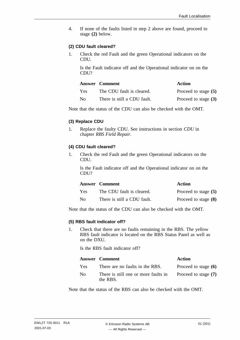
4. If none of the faults listed in step 2 above are found, proceed tostage (2) below.
(2) CDU fault cleared?
1. Check the red Fault and the green Operational indicators on theCDU.
Is the Fault indicator off and the Operational indicator on on theCDU?
Answer Comment Action
Yes The CDU fault is cleared. Proceed to stage (5)
No There is still a CDU fault. Proceed to stage (3)
Note that the status of the CDU can also be checked with the OMT.
(3) Replace CDU
1. Replace the faulty CDU. See instructions in section CDU inchapter RBS Field Repair.
(4) CDU fault cleared?
1. Check the red Fault and the green Operational indicators on theCDU.
Is the Fault indicator off and the Operational indicator on on theCDU?
Answer Comment Action
Yes The CDU fault is cleared. Proceed to stage (5)
No There is still a CDU fault. Proceed to stage (8)
Note that the status of the CDU can also be checked with the OMT.
(5) RBS fault indicator off?
1. Check that there are no faults remaining in the RBS. The yellowRBS fault indicator is located on the RBS Status Panel as well ason the DXU.
Is the RBS fault indicator off?
Answer Comment Action
Yes There are no faults in the RBS. Proceed to stage (6)
No There is still one or more faults inthe RBS.
Proceed to stage (7)
Note that the status of the RBS can also be checked with the OMT.
EN/LZT 720 0011 R1A
2001-07-0351 (201)© Ericsson Radio Systems AB
— All Rights Reserved —
Fault Localisation
(6) Test after repair
1. Make a test call over the CDU concerned. Proceed to section TestCall in chapter Test after Repair.
2. Proceed to section Before Leaving the Site in chapter ConcludingRoutines.
(7) Localise remaining faults
1. Use the monitor Display Faulty RUs in the OMT to list all RUsthat are faulty.
2. Localise the faults that are listed by the OMT. See respective RUsection in chapter Fault Localisation.
(8) Contact supervisor
1. Contact the supervisor, or manager, who will take further action,for example, to consult an FSC.
4.9 CDU Bus/IOM busNote: This section will be included in the next release.
4.10 CDU CXU RXA Cable and CDU CXU RXB CableNote: The fault text is always CDU CXU RXA cable and CDU
CXU RXB cable. For simplicity reasons, the expressionCable fault is used in the procedure below.
52 (201) EN/LZT 720 0011 R1A
2001-07-03© Ericsson Radio Systems AB
— All Rights Reserved —
Fault Localisation
����,���
���+
�������������+��
�.� ����������$
�#���
����� ���#+��0����
8�
8�
����
������� ���� ���&�
�#��%� (��
,�(����#�� �����9
"��+� ����
��(����#�� �����9
8�
6��+� ����
-�(����#�� �����9
:��
!�����#��
��� �������9
:��
:��
8�
:��
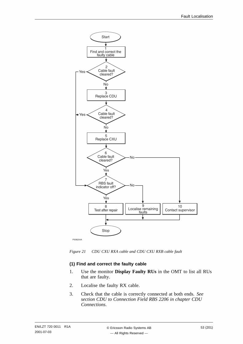
Figure 21 CDU CXU RXA cable and CDU CXU RXB cable fault
(1) Find and correct the faulty cable
1. Use the monitor Display Faulty RUs in the OMT to list all RUsthat are faulty.
2. Localise the faulty RX cable.
3. Check that the cable is correctly connected at both ends. Seesection CDU to Connection Field RBS 2206 in chapter CDUConnections.
EN/LZT 720 0011 R1A
2001-07-0353 (201)© Ericsson Radio Systems AB
— All Rights Reserved —
Fault Localisation
4. Check that the cable connectors are correctly inserted into themating connectors in the CDU and the CXU.
5. If the fault does not disappear, replace the faulty cable.
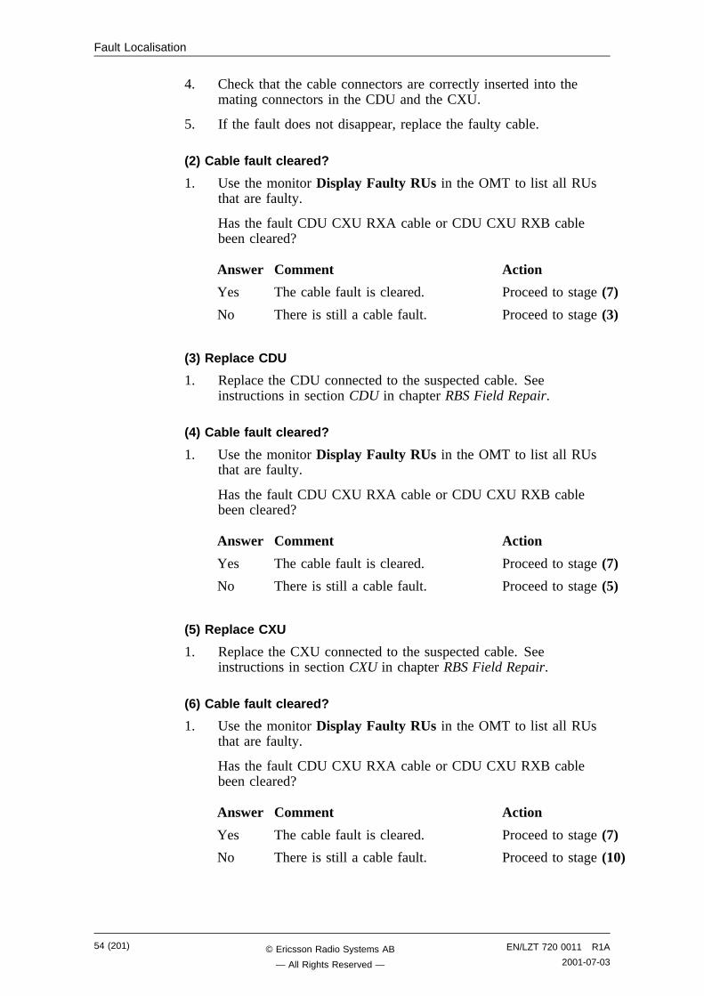
(2) Cable fault cleared?
1. Use the monitor Display Faulty RUs in the OMT to list all RUsthat are faulty.
Has the fault CDU CXU RXA cable or CDU CXU RXB cablebeen cleared?
Answer Comment Action
Yes The cable fault is cleared. Proceed to stage (7)
No There is still a cable fault. Proceed to stage (3)
(3) Replace CDU
1. Replace the CDU connected to the suspected cable. Seeinstructions in section CDU in chapter RBS Field Repair.
(4) Cable fault cleared?
1. Use the monitor Display Faulty RUs in the OMT to list all RUsthat are faulty.
Has the fault CDU CXU RXA cable or CDU CXU RXB cablebeen cleared?
Answer Comment Action
Yes The cable fault is cleared. Proceed to stage (7)
No There is still a cable fault. Proceed to stage (5)
(5) Replace CXU
1. Replace the CXU connected to the suspected cable. Seeinstructions in section CXU in chapter RBS Field Repair.
(6) Cable fault cleared?
1. Use the monitor Display Faulty RUs in the OMT to list all RUsthat are faulty.
Has the fault CDU CXU RXA cable or CDU CXU RXB cablebeen cleared?
Answer Comment Action
Yes The cable fault is cleared. Proceed to stage (7)
No There is still a cable fault. Proceed to stage (10)
54 (201) EN/LZT 720 0011 R1A
2001-07-03© Ericsson Radio Systems AB
— All Rights Reserved —
Fault Localisation
(7) RBS fault indicator off?
1. Check that there are no faults remaining in the RBS. The yellowRBS fault indicator is located on the RBS Status Panel as well ason the DXU.
Is the RBS fault indicator off?
Answer Comment Action
Yes There are no faults in the RBS. Proceed to stage (8)
No There is still one or more faults inthe RBS.
Proceed to stage (9)
Note that the status of the RBS can also be checked with the OMT.
(8) Test after repair
1. Make a test call over the CDU concerned. Proceed to section TestCall in chapter Test after Repair.
2. Proceed to section Before Leaving the Site in chapter ConcludingRoutines.
(9) Localise remaining faults
1. Use the monitor Display Faulty RUs in the OMT to list all RUsthat are faulty.
2. Localise the faults that are listed by the OMT. See respective RUsection in chapter Fault Localisation.
(10) Contact supervisor
1. Contact the supervisor, or manager, who will take further action,for example, to consult an FSC.
4.11 CDU RX in CableNote: The fault text is always CDU RX in cable. For simplicity
reasons, the expression Cable fault is used in the procedurebelow.
EN/LZT 720 0011 R1A
2001-07-0355 (201)© Ericsson Radio Systems AB
— All Rights Reserved —

Fault Localisation
����"���
-����������������+���
!.� ����������$
�#���
���� ���#+��0����
8�
8�
����
������� ���� ��&���#��%� (��
"��+� ����
��(����#�� �����9
:��
6�����#��
��� �������9
:��
:��
8�
���+
,�(����#�� �����9
Figure 22 CDU RX in cable fault
(1) Find and correct the faulty cable
1. Use the monitor Display Faulty RUs in the OMT to list all RUsthat are faulty.
2. Look for "Fault Status CDU RX IN #1". For example, if CDURX IN CABLE 2 is faulty, it means that the faulty cable islocated on CDU 2.
3. Check that the correct cable is connected to the CDU. See sectionCDU Antenna Connection Field RBS 2206 in chapter CDUConnections.
4. Check that the cable connector is correctly inserted into theconnector on the CDU.
5. If the fault does not disappear, replace the faulty cable.
56 (201) EN/LZT 720 0011 R1A
2001-07-03© Ericsson Radio Systems AB
— All Rights Reserved —
Fault Localisation
(2) Cable fault cleared?
1. Use the monitor Display Faulty RUs in the OMT to list all RUsthat are faulty.
Has the fault CDU RX in cable disappeared?
Answer Comment Action
Yes The cable fault is cleared. Proceed to stage (5)
No There is still a cable fault. Proceed to stage (3)
(3) Replace CDU
1. Replace the CDU connected to the suspected cable. Seeinstructions in section CDU in chapter RBS Field Repair.
(4) Cable fault cleared?
1. Use the monitor Display Faulty RUs in the OMT to list all RUsthat are faulty.
Has the fault CDU RX in cable disappeared?
Answer Comment Action
Yes The cable fault is cleared. Proceed to stage (5)
No There is still a cable fault. Proceed to stage (8)
(5) RBS fault indicator off?
1. Check that there are no remaining faults in the RBS. The yellowRBS fault indicator is located on the RBS Status Panel as well ason the DXU.
Is the RBS fault indicator off?
Answer Comment Action
Yes There are no faults in the RBS. Proceed to stage (6)
No There is still one or more faults inthe RBS.
Proceed to stage (7)
Note that the status of the RBS can also be checked with the OMT.
(6) Test after repair
1. Make a test call over the CDU concerned. Proceed to section TestCall in chapter Test after Repair.
2. Proceed to section Before Leaving the Site in chapter ConcludingRoutines.
(7) Localise remaining faults
1. Use the monitor Display Faulty RUs in the OMT to list all RUsthat are faulty.
EN/LZT 720 0011 R1A
2001-07-0357 (201)© Ericsson Radio Systems AB
— All Rights Reserved —
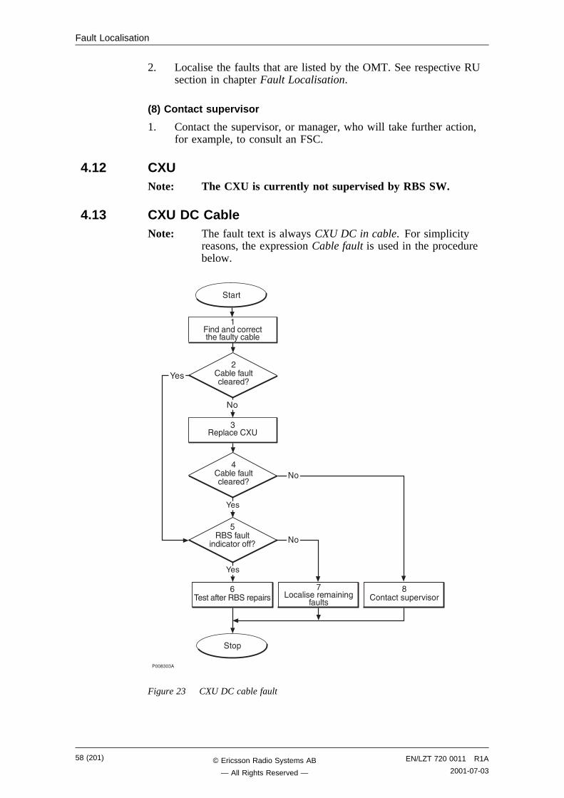
Fault Localisation
2. Localise the faults that are listed by the OMT. See respective RUsection in chapter Fault Localisation.
(8) Contact supervisor
1. Contact the supervisor, or manager, who will take further action,for example, to consult an FSC.
4.12 CXUNote: The CXU is currently not supervised by RBS SW.
4.13 CXU DC CableNote: The fault text is always CXU DC in cable. For simplicity
reasons, the expression Cable fault is used in the procedurebelow.
����"�"�
-����������������+���
!.� ����������$
�#���
���� ���#+��0����
8�
8�
����
������� ���� ��&���#��%� (��
"��+� ����
��(����#�� �����9
:��
6�����#��
��� �������9
:��
:��
8�
���+
,�(����#�� �����9
Figure 23 CXU DC cable fault
58 (201) EN/LZT 720 0011 R1A
2001-07-03© Ericsson Radio Systems AB
— All Rights Reserved —
Fault Localisation
(1) Find and correct the faulty cable
1. Use the monitor Display Faulty RUs in the OMT to list all RUsthat are faulty.
2. Localise the faulty CXU DC cable.
3. Check that the cable is correctly connected at both ends. Seesection Backplane Cables in chapter Cable Connections.
4. Check that the cable connector as well as the correspondingconnector in the CXU are not burned or mechanically damaged.
5. Check that the cable connector is correctly inserted into themating connector in the CXU.
6. If the fault does not disappear, replace the faulty cable.
(2) Cable fault cleared?
1. Use the monitor Display Faulty RUs in the OMT to list all RUsthat are faulty.
Has the fault CXU DC cable disappeared?
Answer Comment Action
Yes The cable fault is cleared. Proceed to stage (5)
No There is still a cable fault. Proceed to stage (3)
(3) Replace CXU
1. Replace the CXU connected to the suspected cable. Seeinstructions in section CXU in chapter RBS Field Repair.
(4) Cable fault cleared?
1. Use the monitor Display Faulty RUs in the OMT to list all RUsthat are faulty.
Has the fault CXU DC cable disappeared?
Answer Comment Action
Yes The cable fault is cleared. Proceed to stage (5)
No There is still a cable fault. Proceed to stage (8)
(5) RBS fault indicator off?
1. Check that there are no faults remaining in the RBS. The yellowRBS fault indicator is located on the RBS Status Panel as well ason the DXU.
Is the RBS fault indicator off?
EN/LZT 720 0011 R1A
2001-07-0359 (201)© Ericsson Radio Systems AB
— All Rights Reserved —
Fault Localisation
Answer Comment Action
Yes There are no faults in the RBS. Proceed to stage (6)
No There is still one or more faults inthe RBS.
Proceed to stage (7)
Note that the status of the RBS can also be checked with the OMT.
(6) Test after repair
1. Make test calls over all TRUs. Proceed to section Test Call inchapter Test after Repair.
2. Proceed to section Before Leaving the Site in chapter ConcludingRoutines.
(7) Localise remaining faults
1. Use the monitor Display Faulty RUs in the OMT to list all RUsthat are faulty.
2. Localise the faults that are listed by the OMT. See respective RUsection in chapter Fault Localisation.
(8) Contact supervisor
1. Contact the supervisor, or manager, who will take further action,for example, to consult an FSC.
4.14 CXU dTRU RXA Cable and CXU dTRU RXB CableNote: The fault text is always CXU dTRU RXA cable and CXU
dTRU RXB cable. For simplicity reasons, the expressionCable fault is used in the procedure below.
60 (201) EN/LZT 720 0011 R1A
2001-07-03© Ericsson Radio Systems AB
— All Rights Reserved —

Fault Localisation
����"�,�
���+
�������������+��
�.� ����������$
�#���
����� ���#+��0����
8�
8�
����
������� ���� ���&�
�#��%� (��
,�(����#�� �����9
"��+� ����
��(����#�� �����9
8�
6��+� ����
-�(����#�� �����9
:��
!�����#��
��� �������9
:��
:��
8�
:��
Figure 24 CXU dTRU RXA cable and CXU dTRU RXB cable fault
(1) Find and correct the faulty cable
1. Use the monitor Display Faulty RUs in the OMT to list all RUsthat are faulty.
2. Localise the faulty RX cable.
3. Check that the cable is correctly connected in both ends. Seesection CDU to Connection Field RBS 2206 in chapter CDUConnections.
EN/LZT 720 0011 R1A
2001-07-0361 (201)© Ericsson Radio Systems AB
— All Rights Reserved —
Fault Localisation
4. Check that the cable connectors are correctly inserted into themating connectors in the dTRU and the CXU.
5. If the fault does not disappear, replace the faulty cable.
(2) Cable fault cleared?
1. Use the monitor Display Faulty RUs in the OMT to list all RUsthat are faulty.
Has the fault CXU dTRU RXA cable or CXU dTRU RXB cablebeen cleared?
Answer Comment Action
Yes The cable fault is cleared. Proceed to stage (7)
No There is still a cable fault. Proceed to stage (3)
(3) Replace TRU
1. Replace the TRU (dTRU) connected to the suspected cable. Seeinstructions in section TRU in chapter RBS Field Repair.
(4) Cable fault cleared?
1. Use the monitor Display Faulty RUs in the OMT to list all RUsthat are faulty.
Has the fault CXU dTRU RXA cable or CXU dTRU RXB cablebeen cleared?
Answer Comment Action
Yes The cable fault is cleared. Proceed to stage (7)
No There is still a cable fault. Proceed to stage (5)
(5) Replace CXU
1. Replace the CXU connected to the suspected cable. Seeinstructions in section CXU in chapter RBS Field Repair.
(6) Cable fault cleared?
1. Use the monitor Display Faulty RUs in the OMT to list all RUsthat are faulty.
Has the fault CXU dTRU RXA cable or CXU dTRU RXB cablebeen cleared?
Answer Comment Action
Yes The cable fault is cleared. Proceed to stage (7)
No There is still a cable fault. Proceed to stage (10)
62 (201) EN/LZT 720 0011 R1A
2001-07-03© Ericsson Radio Systems AB
— All Rights Reserved —
Fault Localisation
(7) RBS fault indicator off?
1. Check that there are no faults remaining in the RBS. The yellowRBS fault indicator is located on the RBS Status Panel as well ason the DXU.
Is the RBS fault indicator off?
Answer Comment Action
Yes There are no faults in the RBS. Proceed to stage (8)
No There is still one or more faults inthe RBS.
Proceed to stage (9)
Note that the status of the RBS can also be checked with the OMT.
(8) Test after repair
1. Make a test call over the CDU concerned. Proceed to section TestCall in chapter Test after Repair.
2. Proceed to section Before Leaving the Site in chapter ConcludingRoutines.
(9) Localise remaining faults
1. Use the monitor Display Faulty RUs in the OMT to list all RUsthat are faulty.
2. Localise the faults that are listed by the OMT. See respective RUsection in chapter Fault Localisation.
(10) Contact supervisor
1. Contact the supervisor, or manager, who will take further action,for example, to consult an FSC.
EN/LZT 720 0011 R1A
2001-07-0363 (201)© Ericsson Radio Systems AB
— All Rights Reserved —
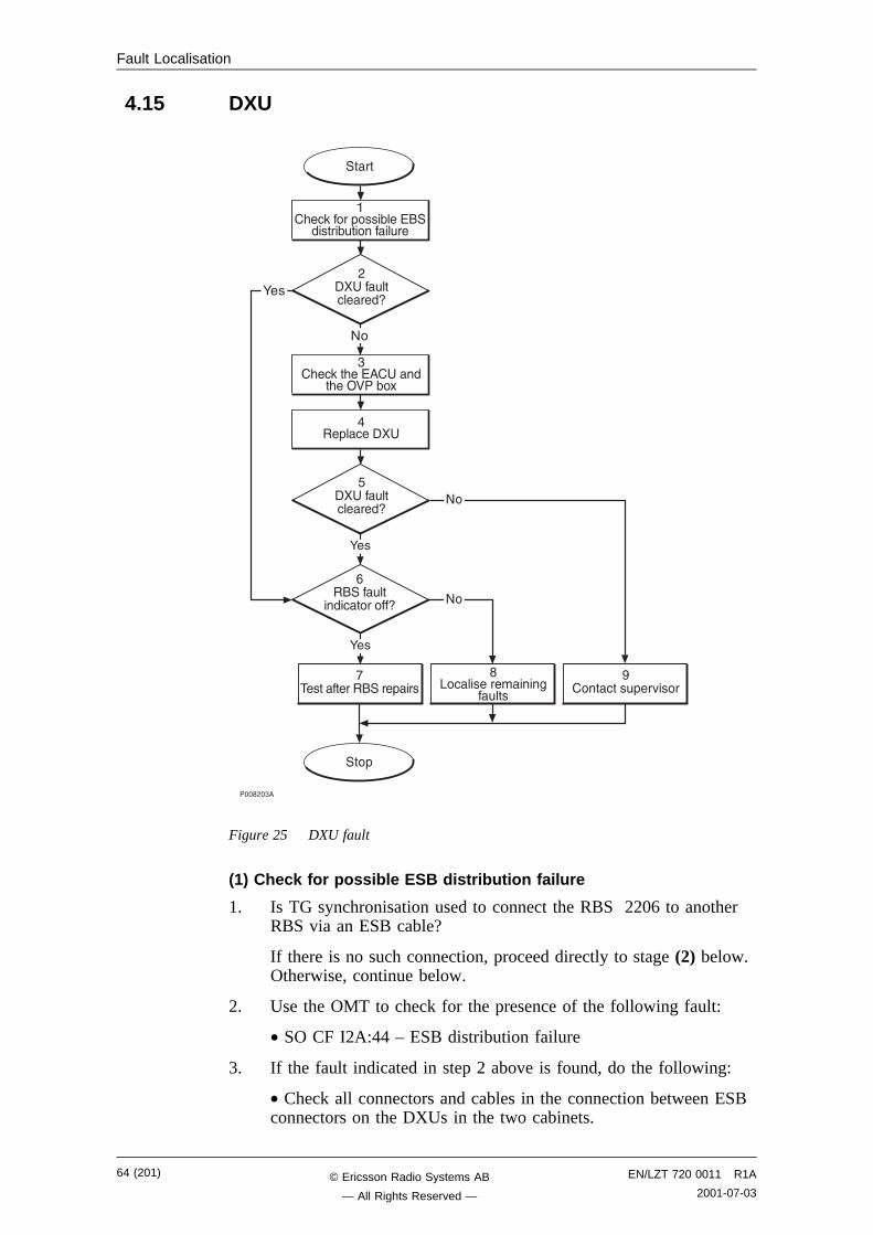
Fault Localisation
4.15 DXU
����,�"�
���+
!����������������+���
�.� ����������$
�#���
���� ���#+��0����
8�
8�
����
��&� 3�����+����(���)��
������(#�������#��
,�� ��#�� �����9
"�&� 3��&��)�� ��
�&��1<��(�*
:��
-�����#��
��� �������9
:��
:��
8�
���+� ����
6�� ��#�� �����9
Figure 25 DXU fault
(1) Check for possible ESB distribution failure
1. Is TG synchronisation used to connect the RBS 2206 to anotherRBS via an ESB cable?
If there is no such connection, proceed directly to stage (2) below.Otherwise, continue below.
2. Use the OMT to check for the presence of the following fault:
• SO CF I2A:44 – ESB distribution failure
3. If the fault indicated in step 2 above is found, do the following:
• Check all connectors and cables in the connection between ESBconnectors on the DXUs in the two cabinets.
64 (201) EN/LZT 720 0011 R1A
2001-07-03© Ericsson Radio Systems AB
— All Rights Reserved —
Fault Localisation
• If the external ESB cable is suspected to be faulty, replace thecable. See instructions in section ESB cable in chapter RBS FieldRepair.
(2) DXU fault cleared?
1. Check the red Fault and the green Operational indicators on theDXU.
Is the Fault indicator off and the Operational indicator on on theDXU?
Answer Comment Action
Yes The DXU fault is cleared. Proceed to stage (6)
No There is still a DXU fault. Proceed to stage (3)
Note that the status of the DXU can also be checked with the OMT.
(3) Check the EACU and the OVP box
Note: When a fault is suspected in the DXU, the overvoltagearrestors in the EACU and the OVP functions of the DFmust be replaced. If the DXU is faulty, due to surges causedby lightning, then the overvoltage arrestors in the EACUand the OVP functions of the DF are likely to be faulty.
1. Replace the overvoltage arrestors in the EACU functions of theDF.
2. If the PCM connection or ESB cable is routed via the DF, thenthe overvoltage arrestors in the OVP functions of the DF must bereplaced.
(4) Replace DXU
1. Replace the faulty DXU according to instructions in section DXUin chapter RBS Field Repair.
(5) DXU fault cleared?
1. Check the red Fault and the green Operational indicators on theDXU.
Is the Fault indicator off and the Operational indicator on on theDXU?
Answer Comment Action
Yes The DXU fault is cleared. Proceed to stage (6)
No There is still a DXU fault. Proceed to stage (9)
Note that the status of the DXU can also be checked with the OMT.
EN/LZT 720 0011 R1A
2001-07-0365 (201)© Ericsson Radio Systems AB
— All Rights Reserved —
Fault Localisation
(6) RBS fault indicator off?
1. Check that there are no faults remaining in the RBS. The yellowRBS fault indicator is located on the RBS Status Panel as well ason the DXU.
Is the RBS fault indicator off?
Answer Comment Action
Yes There are no faults in the RBS. Proceed to stage (7)
No There is still one or more faults inthe RBS.
Proceed to stage (8)
Note that the status of the RBS can also be checked with the OMT.
(7) Test after repair
1. Make a test call over all TRUs. Proceed to section Test Call inchapter Test after Repair.
2. Proceed to section Before Leaving the Site in chapter ConcludingRoutines.
(8) Localise remaining faults
1. Use the monitor Display Faulty RUs in the OMT to list all RUsthat are faulty.
2. Localise the faults that are listed by the OMT. See respective RUsection in chapter Fault Localisation.
(9) Contact supervisor
1. Contact the supervisor, or manager, who will take further action,for example, to consult an FSC.
4.16 EnvironmentNote: This section will be included in the next release.
4.17 EOM BusNote: This section will be included in the next release.
4.18 EPC Bus/Power Communication LoopThe EPC bus is a fibre optic loop used for control and supervision ofthe power system. When the loop is opened, the power system switchesto stand alone mode and the fault EPC bus/Power Communication Loopis set in the RU map.
Possible faults are a faulty RU or a faulty fibre optic cable. Theindicator EPC bus fault will be lit on the DXU and on those RUs thathave lost communication with the EPC function of the DXU.
66 (201) EN/LZT 720 0011 R1A
2001-07-03© Ericsson Radio Systems AB
— All Rights Reserved —
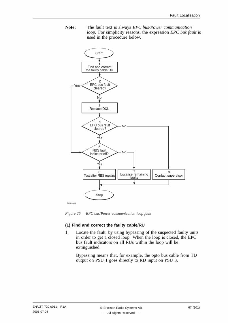
Fault Localisation
Note: The fault text is always EPC bus/Power communicationloop. For simplicity reasons, the expression EPC bus fault isused in the procedure below.
����"�6�
-����������������+���
!.� ����������$
�#���
���� ���#+��0����
8�
8�
����
������� ���� �
�&���#��%� (��=�
"��+� ����
�)���(#���#��
�����9
:��
6�����#��
��� �������9
:��
:��
8�
���+
,)���(#���#��
�����9
Figure 26 EPC bus/Power communication loop fault
(1) Find and correct the faulty cable/RU
1. Locate the fault, by using bypassing of the suspected faulty unitsin order to get a closed loop. When the loop is closed, the EPCbus fault indicators on all RUs within the loop will beextinguished.
Bypassing means that, for example, the opto bus cable from TDoutput on PSU 1 goes directly to RD input on PSU 3.
EN/LZT 720 0011 R1A
2001-07-0367 (201)© Ericsson Radio Systems AB
— All Rights Reserved —

Fault Localisation
����"�-�
��
��
����
����
�� �� �� �, �� �" �� �� ��
��
�� ��
��
��
��
��
�����,���
��
��
�#��% �� ���
��� ��$'��
��� ������+��� �� ���
��
��
)���(#���#���������&����#���
Figure 27 Example of a fault situation in the power communication loop
2. Repeat the bypass until the faulty RU or cable is identified.
3. • If found to be faulty, replace the EPC bus cable.
• If found to be faulty, replace any faulty RU in the RBS cabinetaccording to instructions in section PSU, FCU or DXU in chapterRBS Field Repair.
• If found to be faulty, replace the BFU in the external batterysystem. See manufacturer’s documentation.
Note: The opto bus cables must have a bending radius of at least35 mm.
(2) EPC bus fault cleared?
1. Check the yellow indicator EPC bus fault on each RU connectedto the EPC bus.
Is the indicator EPC bus fault off on each RU connected to theEPC bus?
Answer Comment Action
Yes The EPC bus fault is cleared. Proceed to stage (5)
No There is still an EPC bus fault. Proceed to stage (3)
Note that the status of the EPC bus can also be checked with the OMT.
68 (201) EN/LZT 720 0011 R1A
2001-07-03© Ericsson Radio Systems AB
— All Rights Reserved —
Fault Localisation
(3) Replace DXU
1. Replace the faulty DXU according to instructions in section DXUin chapter RBS Field Repair.
(4) EPC bus fault cleared?
1. Check the yellow indicator EPC bus fault on all RUs connected tothe EPC bus.
Is the indicator EPC bus fault off on all RUs connected to theEPC bus?
Answer Comment Action
Yes The EPC bus fault is cleared. Proceed to stage (5)
No There is still an EPC bus fault. Proceed to stage (8)
Note that the status of the EPC bus can also be checked with the OMT.
(5) RBS fault indicator off?
1. Check that there are no faults remaining in the RBS. The yellowRBS fault indicator is located on the RBS Status Panel as well ason the DXU.
Is the RBS fault indicator off?
Answer Comment Action
Yes There are no faults in the RBS. Proceed to stage (6)
No There is still one or more faults inthe RBS.
Proceed to stage (7)
Note that the status of the RBS can also be checked with the OMT.
(6) Test after repair
1. (Only if the DXU has been replaced ) Make test calls over allTRUs. Proceed to section Test Call in chapter Test after Repair.
2. Proceed to section Before Leaving the Site in chapter ConcludingRoutines.
(7) Localise remaining faults
1. Use the monitor Display Faulty RUs in the OMT to list all RUsthat are faulty.
2. Localise the faults that are listed by the OMT. See respective RUsection in chapter Fault Localisation.
(8) Contact supervisor
1. Contact the supervisor, or manager, who will take further action,for example, to consult an FSC.
EN/LZT 720 0011 R1A
2001-07-0369 (201)© Ericsson Radio Systems AB
— All Rights Reserved —
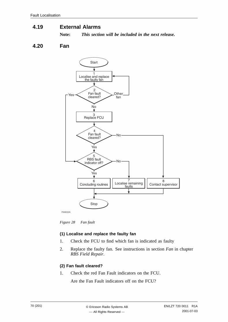
Fault Localisation
4.19 External AlarmsNote: This section will be included in the next release.
4.20 Fan
����"",�
-�� �#��$���#����
!.� ����������$
�#���
���� ���#+��0����
8�
8�
����
����#�� �����9
:��
6�����#��
��� �������9
:��
8�
���+
,���#�� �����9
�.� ���������+� �
�&���#��%��
:��
"��+� ����
1�&���
Figure 28 Fan fault
(1) Localise and replace the faulty fan
1. Check the FCU to find which fan is indicated as faulty
2. Replace the faulty fan. See instructions in section Fan in chapterRBS Field Repair.
(2) Fan fault cleared?
1. Check the red Fan Fault indicators on the FCU.
Are the Fan Fault indicators off on the FCU?
70 (201) EN/LZT 720 0011 R1A
2001-07-03© Ericsson Radio Systems AB
— All Rights Reserved —
Fault Localisation
Answer Comment Action
Yes The Fan fault is cleared. Proceed to stage (5)
No The same fan is indicated as faulty. Proceed to stage (3)
Otherfan
Another fan is indicated as faulty. Go back to stage (1)
Note that the status of the fans can also be checked with the OMT.
(3) Replace FCU
1. Replace the FCU according to instructions in section FCU inchapter RBS Field Repair.
(4) Fan fault cleared?
1. Check the red Fan Fault indicators on the FCU.
Are the Fan Fault indicators off on the FCU?
Answer Comment Action
Yes The Fan fault is cleared. Proceed to stage (5)
No There is still a Fan fault. Proceed to stage (8)
Note that the status of the fans can also be checked with the OMT.
(5) RBS fault indicator off?
1. Check that there are no faults remaining in the RBS. The yellowRBS fault indicator is located on the RBS Status Panel as well ason the DXU.
Is the RBS fault indicator off?
Answer Comment Action
Yes There are no faults in the RBS. Proceed to stage (6)
No There is still one or more faults inthe RBS.
Proceed to stage (7)
Note that the status of the RBS can also be checked with the OMT.
(6) Concluding routines
1. Proceed to section Before Leaving the Site in chapter ConcludingRoutines.
(7) Localise remaining faults
1. Use the monitor Display Faulty RUs in the OMT to list all RUsthat are faulty.
2. Localise the faults that are listed by the OMT. See respective RUsection in chapter Fault Localisation.
EN/LZT 720 0011 R1A
2001-07-0371 (201)© Ericsson Radio Systems AB
— All Rights Reserved —
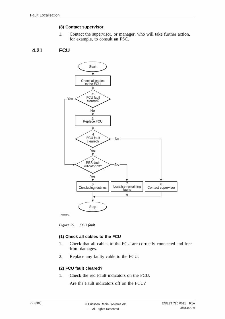
Fault Localisation
(8) Contact supervisor
1. Contact the supervisor, or manager, who will take further action,for example, to consult an FSC.
4.21 FCU
����""��
-�� �#��$���#����
!.� ����������$
�#���
���� ���#+��0����
8�
8�
����
��� ��#�� �����9
:��
6�����#��
��� �������9
:��
8�
���+
,�� ��#�� �����9
��&� 3���� (���
����&����
:��
"��+� ����
Figure 29 FCU fault
(1) Check all cables to the FCU
1. Check that all cables to the FCU are correctly connected and freefrom damages.
2. Replace any faulty cable to the FCU.
(2) FCU fault cleared?
1. Check the red Fault indicators on the FCU.
Are the Fault indicators off on the FCU?
72 (201) EN/LZT 720 0011 R1A
2001-07-03© Ericsson Radio Systems AB
— All Rights Reserved —
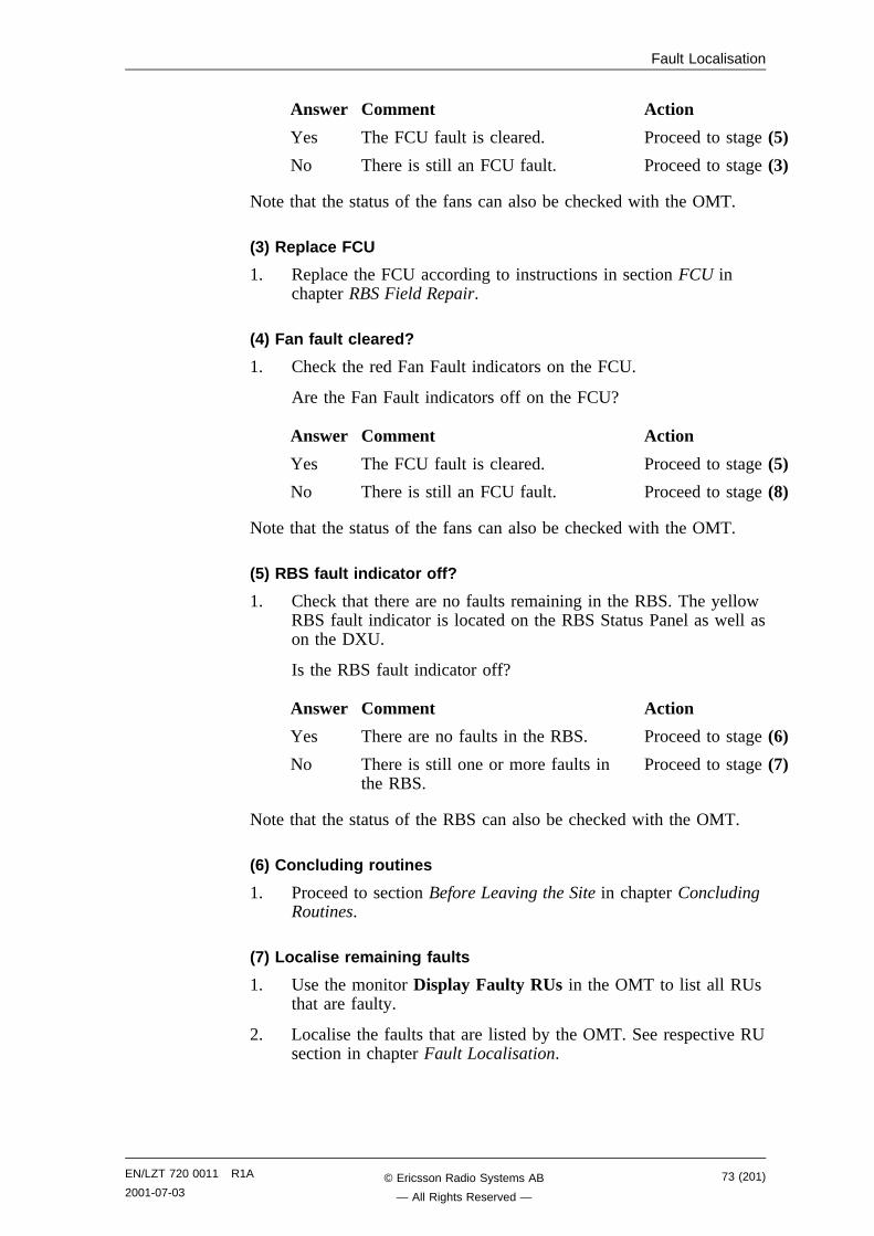
Fault Localisation
Answer Comment Action
Yes The FCU fault is cleared. Proceed to stage (5)
No There is still an FCU fault. Proceed to stage (3)
Note that the status of the fans can also be checked with the OMT.
(3) Replace FCU
1. Replace the FCU according to instructions in section FCU inchapter RBS Field Repair.
(4) Fan fault cleared?
1. Check the red Fan Fault indicators on the FCU.
Are the Fan Fault indicators off on the FCU?
Answer Comment Action
Yes The FCU fault is cleared. Proceed to stage (5)
No There is still an FCU fault. Proceed to stage (8)
Note that the status of the fans can also be checked with the OMT.
(5) RBS fault indicator off?
1. Check that there are no faults remaining in the RBS. The yellowRBS fault indicator is located on the RBS Status Panel as well ason the DXU.
Is the RBS fault indicator off?
Answer Comment Action
Yes There are no faults in the RBS. Proceed to stage (6)
No There is still one or more faults inthe RBS.
Proceed to stage (7)
Note that the status of the RBS can also be checked with the OMT.
(6) Concluding routines
1. Proceed to section Before Leaving the Site in chapter ConcludingRoutines.
(7) Localise remaining faults
1. Use the monitor Display Faulty RUs in the OMT to list all RUsthat are faulty.
2. Localise the faults that are listed by the OMT. See respective RUsection in chapter Fault Localisation.
EN/LZT 720 0011 R1A
2001-07-0373 (201)© Ericsson Radio Systems AB
— All Rights Reserved —
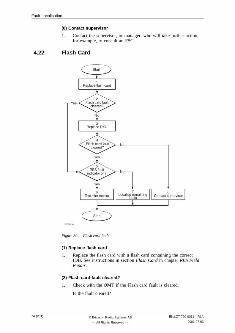
Fault Localisation
(8) Contact supervisor
1. Contact the supervisor, or manager, who will take further action,for example, to consult an FSC.
4.22 Flash Card
����,�6�
-������������+���
!.� ����������$
�#���
���� ���#+��0����
8�
8�
����
���+� �����&� ��
,���&� ����#��
�����9
"��+� ����
����&� ����#��
�����9
:��
6�����#��
��� �������9
:��
:��
8�
���+
Figure 30 Flash card fault
(1) Replace flash card
1. Replace the flash card with a flash card containing the correctIDB. See instructions in section Flash Card in chapter RBS FieldRepair.
(2) Flash card fault cleared?
1. Check with the OMT if the Flash card fault is cleared.
Is the fault cleared?
74 (201) EN/LZT 720 0011 R1A
2001-07-03© Ericsson Radio Systems AB
— All Rights Reserved —
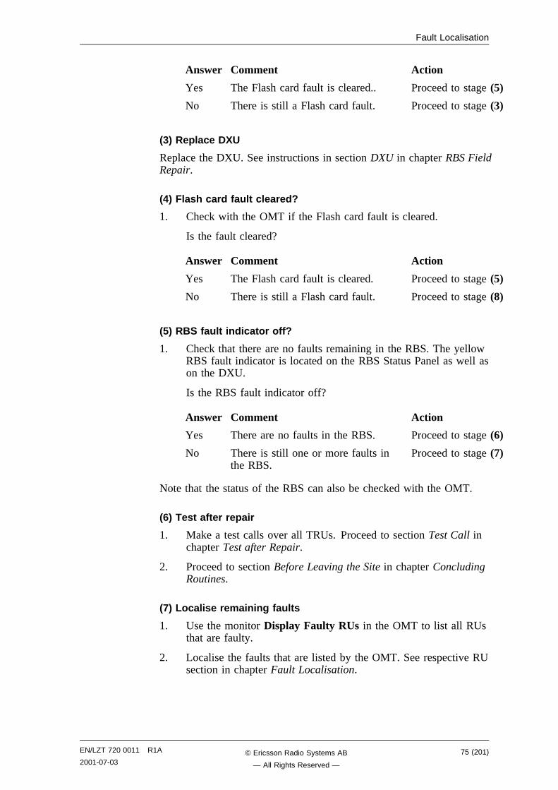
Fault Localisation
Answer Comment Action
Yes The Flash card fault is cleared.. Proceed to stage (5)
No There is still a Flash card fault. Proceed to stage (3)
(3) Replace DXU
Replace the DXU. See instructions in section DXU in chapter RBS FieldRepair.
(4) Flash card fault cleared?
1. Check with the OMT if the Flash card fault is cleared.
Is the fault cleared?
Answer Comment Action
Yes The Flash card fault is cleared. Proceed to stage (5)
No There is still a Flash card fault. Proceed to stage (8)
(5) RBS fault indicator off?
1. Check that there are no faults remaining in the RBS. The yellowRBS fault indicator is located on the RBS Status Panel as well ason the DXU.
Is the RBS fault indicator off?
Answer Comment Action
Yes There are no faults in the RBS. Proceed to stage (6)
No There is still one or more faults inthe RBS.
Proceed to stage (7)
Note that the status of the RBS can also be checked with the OMT.
(6) Test after repair
1. Make a test calls over all TRUs. Proceed to section Test Call inchapter Test after Repair.
2. Proceed to section Before Leaving the Site in chapter ConcludingRoutines.
(7) Localise remaining faults
1. Use the monitor Display Faulty RUs in the OMT to list all RUsthat are faulty.
2. Localise the faults that are listed by the OMT. See respective RUsection in chapter Fault Localisation.
EN/LZT 720 0011 R1A
2001-07-0375 (201)© Ericsson Radio Systems AB
— All Rights Reserved —
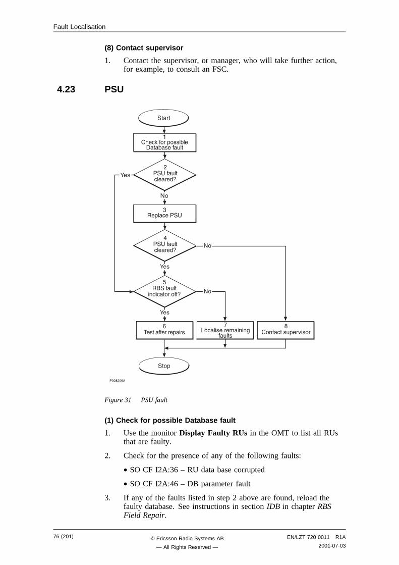
Fault Localisation
(8) Contact supervisor
1. Contact the supervisor, or manager, who will take further action,for example, to consult an FSC.
4.23 PSU
����,�-�
���+
-������������+���
!.� ����������$
�#���
���� ���#+��0����
8�
8�
����
��&� 3�����+����(����(����#��
,�� ��#�� �����9
"��+� ����
��� ��#�� �����9
:��
6�����#��
��� �������9
:��
:��
8�
Figure 31 PSU fault
(1) Check for possible Database fault
1. Use the monitor Display Faulty RUs in the OMT to list all RUsthat are faulty.
2. Check for the presence of any of the following faults:
• SO CF I2A:36 – RU data base corrupted
• SO CF I2A:46 – DB parameter fault
3. If any of the faults listed in step 2 above are found, reload thefaulty database. See instructions in section IDB in chapter RBSField Repair.
76 (201) EN/LZT 720 0011 R1A
2001-07-03© Ericsson Radio Systems AB
— All Rights Reserved —
Fault Localisation
(2) PSU fault cleared?
1. Check the red Fault and the green Operational indicators on thePSU.
Is the Fault indicator off and the Operational indicator on on thePSU?
Answer Comment Action
Yes The PSU fault is cleared. Proceed to stage (5)
No There is still a PSU fault. Proceed to stage (3)
Note that the status of the PSU can also be checked with the OMT.
(3) Replace PSU
1. Replace the faulty PSU. See instructions in section PSU in chapterRBS Field Repair.
(4) PSU fault cleared?
1. Check the red Fault and the green Operational indicators on thePSU.
Is the Fault indicator off and the Operational indicator on on thePSU?
Answer Comment Action
Yes The PSU fault is cleared. Proceed to stage (5)
No There is still a PSU fault. Proceed to stage (8)
Note that the status of the PSU can also be checked with the OMT.
(5) RBS fault indicator off?
1. Check that there are no faults remaining in the RBS. The yellowRBS fault indicator is located on the RBS Status Panel as well ason the DXU.
Is the RBS fault indicator off?
Answer Comment Action
Yes There are no faults in the RBS. Proceed to stage (6)
No There is still one or more faults inthe RBS.
Proceed to stage (7)
Note that the status of the RBS can also be checked with the OMT.
(6) Test after repair
1. Proceed to section Before Leaving the Site in chapter ConcludingRoutines.
EN/LZT 720 0011 R1A
2001-07-0377 (201)© Ericsson Radio Systems AB
— All Rights Reserved —
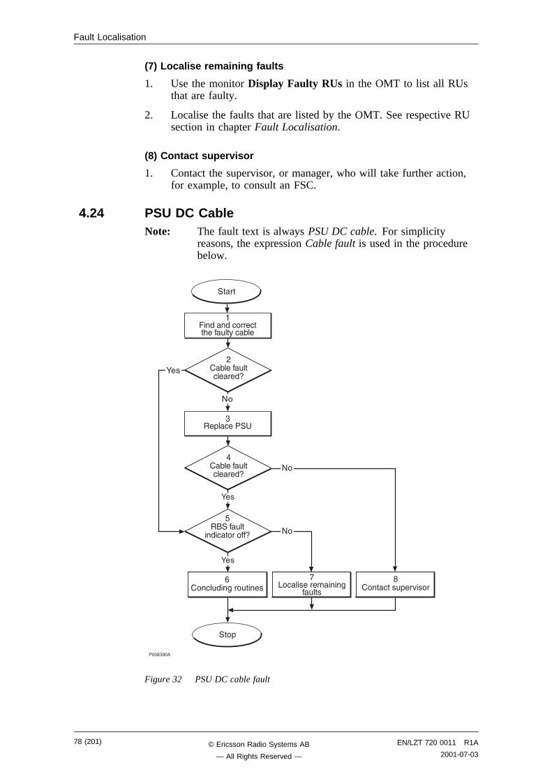
Fault Localisation
(7) Localise remaining faults
1. Use the monitor Display Faulty RUs in the OMT to list all RUsthat are faulty.
2. Localise the faults that are listed by the OMT. See respective RUsection in chapter Fault Localisation.
(8) Contact supervisor
1. Contact the supervisor, or manager, who will take further action,for example, to consult an FSC.
4.24 PSU DC CableNote: The fault text is always PSU DC cable. For simplicity
reasons, the expression Cable fault is used in the procedurebelow.
����"���
-�� �#��$���#����
!.� ����������$
�#���
���� ���#+��0����
8�
8�
����
������� ���� ��&���#��%� (��
"��+� ����
��(����#�� �����9
:��
6�����#��
��� �������9
:��
:��
8�
���+
,�(����#�� �����9
Figure 32 PSU DC cable fault
78 (201) EN/LZT 720 0011 R1A
2001-07-03© Ericsson Radio Systems AB
— All Rights Reserved —
Fault Localisation
(1) Find and correct the faulty cable
1. Use the monitor Display Faulty RUs in the OMT to list all RUsthat are faulty.
2. Localise the faulty PSU DC cable.
3. Check that the cable is correctly connected at both ends. Seesection Power Cables in chapter Cable Connections.
4. Check that the cable connector as well as the correspondingconnector in the PSU are not burned or mechanically damaged.
5. Check that the cable connector is correctly inserted into theconnector in the PSU.
6. If the fault does not disappear, replace the faulty cable.
(2) Cable fault cleared?
1. Use the monitor Display Faulty RUs in the OMT to list all RUsthat are faulty.
Has the fault PSU DC cable disappeared?
Answer Comment Action
Yes The cable fault is cleared. Proceed to stage (5)
No There is still a cable fault. Proceed to stage (3)
(3) Replace PSU
1. Replace the PSU connected to the suspected cable. Seeinstructions in section PSU in chapter RBS Field Repair.
(4) Cable fault cleared?
1. Use the monitor Display Faulty RUs in the OMT to list all RUsthat are faulty.
Has the fault PSU DC cable disappeared?
Answer Comment Action
Yes The cable fault is cleared. Proceed to stage (5)
No There is still a cable fault. Proceed to stage (8)
(5) RBS fault indicator off?
1. Check that there are no faults remaining in the RBS. The yellowRBS fault indicator is located on the RBS Status Panel as well ason the DXU.
Is the RBS fault indicator off?
EN/LZT 720 0011 R1A
2001-07-0379 (201)© Ericsson Radio Systems AB
— All Rights Reserved —
Fault Localisation
Answer Comment Action
Yes There are no faults in the RBS. Proceed to stage (6)
No There is still one or more faults inthe RBS.
Proceed to stage (7)
Note that the status of the RBS can also be checked with the OMT.
(6) Concluding routines
1. Proceed to section Before Leaving the Site in chapter ConcludingRoutines.
(7) Localise remaining faults
1. Use the monitor Display Faulty RUs in the OMT to list all RUsthat are faulty.
2. Localise the faults that are listed by the OMT. See respective RUsection in chapter Fault Localisation.
(8) Contact supervisor
1. Contact the supervisor, or manager, who will take further action,for example, to consult an FSC.
80 (201) EN/LZT 720 0011 R1A
2001-07-03© Ericsson Radio Systems AB
— All Rights Reserved —
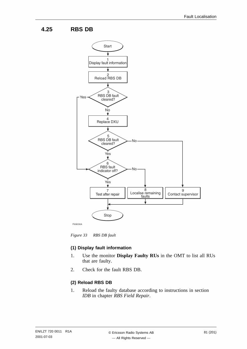
Fault Localisation
4.25 RBS DB
����""��
!������������+��
�.� ����������$
�#���
���� ���#+��0����
8�
8�
����
6��������#�� �����9
:��
-�����#��
��� �������9
:��
8�
���+
"��������#�� �����9
,������������
����+�%��#�����������
:��
���+� ����
Figure 33 RBS DB fault
(1) Display fault information
1. Use the monitor Display Faulty RUs in the OMT to list all RUsthat are faulty.
2. Check for the fault RBS DB.
(2) Reload RBS DB
1. Reload the faulty database according to instructions in sectionIDB in chapter RBS Field Repair.
EN/LZT 720 0011 R1A
2001-07-0381 (201)© Ericsson Radio Systems AB
— All Rights Reserved —
Fault Localisation
(3) RBS DB fault cleared?
1. Use the monitor Display Faulty RUs in the OMT to list all RUsthat are faulty.
2. Check for the fault RBS DB.
Is the RBS DB fault cleared?
Answer Comment Action
Yes The RBS DB fault is cleared. Proceed to stage (6)
No There is still a RBS DB fault. Proceed to stage (4)
(4) Replace DXU
1. Replace the faulty DXU according to instructions in section DXUin chapter RBS Field Repair.
(5) RBS DB fault cleared?
1. Use the monitor Display Faulty RUs in the OMT to list all RUsthat are faulty.
2. Check for the fault RBS DB.
Is the RBS DB fault cleared?
Answer Comment Action
Yes The RBS DB fault is cleared. Proceed to stage (6)
No There is still a RBS DB fault. Proceed to stage (9)
(6) RBS fault indicator status?
1. Check that there are no faults remaining in the RBS. The yellowRBS fault indicator is located on the RBS Status Panel as well ason the DXU.
Is the RBS fault indicator off?
Answer Comment Action
Yes There are no faults in the RBS. Proceed to stage (7)
No There is still one or more faults inthe RBS.
Proceed to stage (8)
Note that the status of the RBS can also be checked with the OMT.
(7) Test after repair
1. Proceed to section Before Leaving the Site in chapter Test afterRepair.
82 (201) EN/LZT 720 0011 R1A
2001-07-03© Ericsson Radio Systems AB
— All Rights Reserved —
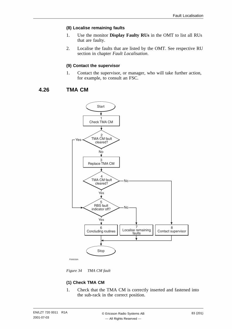
Fault Localisation
(8) Localise remaining faults
1. Use the monitor Display Faulty RUs in the OMT to list all RUsthat are faulty.
2. Localise the faults that are listed by the OMT. See respective RUsection in chapter Fault Localisation.
(9) Contact the supervisor
1. Contact the supervisor, or manager, who will take further action,for example, to consult an FSC.
4.26 TMA CM
����""-�
���+
-�� �#��$���#����
!.� ����������$
�#���
���� ���#+��0����
8�
8�
����
,��������#��
�����9
"��+� ��������
���������#��
�����9
:��
6�����#��
��� �������9
:��
:��
8�
��&� 3�������
Figure 34 TMA CM fault
(1) Check TMA CM
1. Check that the TMA CM is correctly inserted and fastened intothe sub-rack in the correct position.
EN/LZT 720 0011 R1A
2001-07-0383 (201)© Ericsson Radio Systems AB
— All Rights Reserved —
Fault Localisation
2. Check that the TMA power connector is correctly connected tothe TMA CM.
(2) TMA CM fault cleared?
1. Check the red Fault and the green Operational indicators on theTMA CM.
Is the Fault indicator off and the Operational indicator on on theTMA CM?
Answer Comment Action
Yes The TMA CM fault is cleared. Proceed to stage (5)
No There is still a TMA CM fault. Proceed to stage (3)
Note that the status of the TMA CM can also be checked with the OMT.
(3) Replace TMA CM
1. Replace the faulty TMA CM. See instructions in section TMA CMin chapter RBS Field Repair.
(4) TMA CM fault cleared?
1. Check the red Fault and the green Operational indicators on theTMA CM.
Is the Fault indicator off and the Operational indicator on on theTMA CM?
Answer Comment Action
Yes The TMA CM fault is cleared. Proceed to stage (5)
No There is still a TMA CM fault. Proceed to stage (8)
Note that the status of the TMA CM can also be checked with the OMT.
(5) RBS fault indicator off?
1. Check that there are no faults remaining in the RBS. The yellowRBS fault indicator is located on the RBS Status Panel as well ason the DXU.
Is the RBS fault indicator off?
Answer Comment Action
Yes There are no faults in the RBS. Proceed to stage (6)
No There is still one or more faults inthe RBS.
Proceed to stage (7)
Note that the status of the RBS can also be checked with the OMT.
84 (201) EN/LZT 720 0011 R1A
2001-07-03© Ericsson Radio Systems AB
— All Rights Reserved —

Fault Localisation
(6) Test after repair
1. Make test calls over all TRUs. Proceed to section Test Call inchapter Test after Repair.
2. Proceed to section Before Leaving the Site in chapter ConcludingRoutines.
(7) Localise remaining faults
1. Use the monitor Display Faulty RUs in the OMT to list all RUsthat are faulty.
2. Localise the faults that are listed by the OMT. See respective RUsection in chapter Fault Localisation.
(8) Contact supervisor
1. Contact the supervisor, or manager, who will take further action,for example, to consult an FSC.
4.27 TMA CM CableNote: This section will be included in the next release.
4.28 TRU, dTRU or ATRUNote: The fault text is always TRU, dTRU or ATRU. For simplicity
reasons, the expression TRU is used in the procedure below.
EN/LZT 720 0011 R1A
2001-07-0385 (201)© Ericsson Radio Systems AB
— All Rights Reserved —
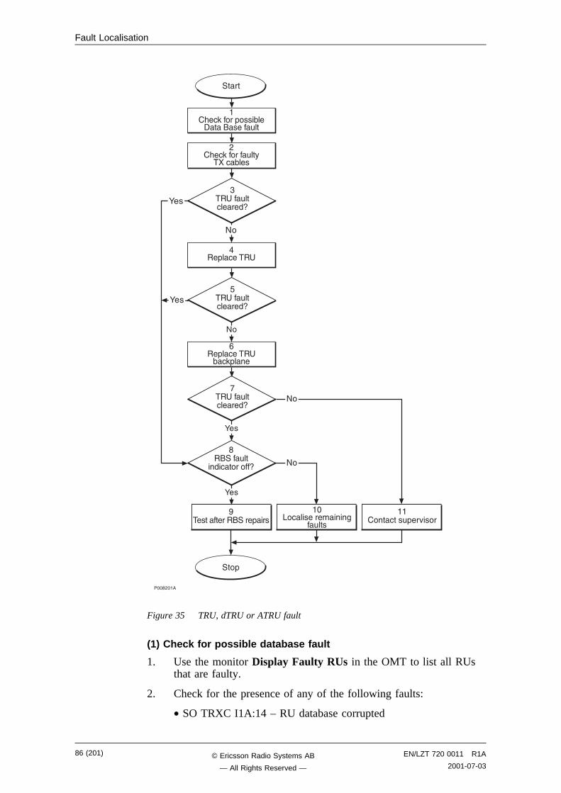
Fault Localisation
����,���
���+
�����������������+���
��.� ����������$
�#���
����� ���#+��0����
8�
8�
����
��&� 3�����+����(����������#��
,�&� 3������#��%
��� (���
"�� ��#�� �����9
���+� ����
6�� ��#�� �����9
8�
-��+� ���� ( 3+��
!�� ��#�� �����9
:��
������#��
��� �������9
:��
:��
8�
:��
Figure 35 TRU, dTRU or ATRU fault
(1) Check for possible database fault
1. Use the monitor Display Faulty RUs in the OMT to list all RUsthat are faulty.
2. Check for the presence of any of the following faults:
• SO TRXC I1A:14 – RU database corrupted
86 (201) EN/LZT 720 0011 R1A
2001-07-03© Ericsson Radio Systems AB
— All Rights Reserved —
Fault Localisation
• SO TRXC I2A:26 – DB parameter fault
3. If any of the faults listed in step 2 above is found, reload thefaulty database. See instructions in section IDB in chapter RBSField Repair.
4. Proceed to stage (2) below..
(2) Check for faulty TX cables
1. Replace one or both CDU-TRU TX cables according toinstructions in section CDU-TRU TX Cables in chapter RBS FieldRepair.
(3) TRU fault cleared?
1. Check the red Fault and the green Operational indicators on theTRU.
Is the Fault indicator off and the Operational indicator on on theTRU?
Answer Comment Action
Yes The TRU fault is cleared. Proceed to stage (8)
No There is still a TRU fault. Proceed to stage (4)
Note that the status of the TRU can also be checked with the OMT.
(4) Replace TRU
1. Replace the faulty TRU according to instructions in section TRUin chapter RBS Field Repair.
(5) TRU fault cleared?
1. Check the red Fault and the green Operational indicators on theTRU.
Is the Fault indicator off and the Operational indicator on on theTRU?
Answer Comment Action
Yes The TRU fault is cleared. Proceed to stage (8)
No There is still a TRU fault. Proceed to stage (6)
Note that the status of the TRU can also be checked with the OMT.
(6) Replace TRU backplane
The fault is probably located in the backplane.
1. Replace the TRU backplane according to section TRU backplanein chapter RBS Field Repair.
EN/LZT 720 0011 R1A
2001-07-0387 (201)© Ericsson Radio Systems AB
— All Rights Reserved —
Fault Localisation
(7) TRU fault cleared?
1. Check the red Fault and the green Operational indicators on theTRU.
Is the Fault indicator off and the Operational indicator on on theTRU?
Answer Comment Action
Yes The TRU fault is cleared. Proceed to stage (8)
No There is still a TRU fault. Proceed to stage (11)
Note that the status of the TRU can also be checked with the OMT.
(8) RBS fault indicator status?
1. Check that there are no faults remaining in the RBS. The yellowRBS fault indicator is located on the RBS Status Panel as well ason the DXU.
Is the RBS fault indicator off?
Answer Comment Action
Yes There are no faults in the RBS. Proceed to stage (9)
No There is still one or more faults inthe RBS.
Proceed to stage (10)
Note that the status of the RBS can also be checked with the OMT.
(9) Test after repair
1. Make a test call:
• If a TRU was replaced, make a test call over that specific TRUaccording to section Test Call in chapter Test after Repair.
• If the TRU backplane was replaced, make test calls over allTRUs according to section Test Call in chapter Test after Repair.
2. Proceed to section Before Leaving the Site in chapter ConcludingRoutines.
(10) Localise remaining faults
1. Use the monitor Display Faulty RUs in the OMT to list all RUsthat are faulty.
2. Localise the faults that are listed by the OMT. See respective RUsection in chapter Fault Localisation.
(11) Contact supervisor
1. Contact the supervisor, or manager, who will take further action,for example, to consult an FSC.
88 (201) EN/LZT 720 0011 R1A
2001-07-03© Ericsson Radio Systems AB
— All Rights Reserved —
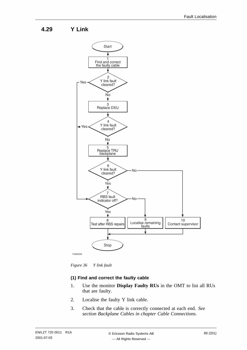
Fault Localisation
4.29 Y Link
����",��
�����������������+���
�.� ����������$
�#���
����� ���#+��0����
8�
8�
����
-:���3��#�� �����9
:��
!�����#��
��� �������9
:��
8�
���+
�:���3��#�� �����9
,:���3��#�� �����9
"��+� ����
������� ���� ��&���#��%� (��
6��+� ���� ( 3+��
8�
:��
:��
Figure 36 Y link fault
(1) Find and correct the faulty cable
1. Use the monitor Display Faulty RUs in the OMT to list all RUsthat are faulty.
2. Localise the faulty Y link cable.
3. Check that the cable is correctly connected at each end. Seesection Backplane Cables in chapter Cable Connections.
EN/LZT 720 0011 R1A
2001-07-0389 (201)© Ericsson Radio Systems AB
— All Rights Reserved —
Fault Localisation
4. Check that the cable connectors are correctly inserted into theconnectors in the DXU and the TRU backplane.
5. If the fault does not disappear, replace the faulty cable.
(2) Y link fault cleared?
1. Use the monitor Display Faulty RUs in the OMT to list all RUsthat are faulty.
Has the Y link fault been cleared?
Answer Comment Action
Yes The Y link fault is cleared. Proceed to stage (7)
No There is still a Y link fault. Proceed to stage (3)
Note that the status of the Y link can also be checked with the OMT.
(3) Replace DXU
1. Replace the DXU according to instructions in section DXU inchapter RBS Field Repair.
(4) Y link fault cleared?
1. Use the monitor Display Faulty RUs in the OMT to list all RUsthat are faulty.
Has the Y link fault been cleared?
Answer Comment Action
Yes The Y link fault is cleared. Proceed to stage (7)
No There is still a Y link fault. Proceed to stage (5)
Note that the status of the Y link can also be checked with the OMT.
(5) Replace TRU backplane
1. Replace the TRU backplane. See instructions in section TRUbackplane in chapter RBS Field Repair.
(6) Y link fault cleared?
1. Use the monitor Display Faulty RUs in the OMT to list all RUsthat are faulty.
Has the Y link fault been cleared?
Answer Comment Action
Yes The Y link fault is cleared. Proceed to stage (7)
No There is still a Y link fault. Proceed to stage (10)
Note that the status of the Y link can also be checked with the OMT.
90 (201) EN/LZT 720 0011 R1A
2001-07-03© Ericsson Radio Systems AB
— All Rights Reserved —
Fault Localisation
(7) RBS fault indicator off?
1. Check that there are no faults remaining in the RBS. The yellowRBS fault indicator is located on the RBS Status Panel as well ason the DXU.
Is the RBS fault indicator off?
Answer Comment Action
Yes There are no faults in the RBS. Proceed to stage (8)
No There is still one or more faults inthe RBS.
Proceed to stage (9)
Note that the status of the RBS can also be checked with the OMT.
(8) Test after repair
1. Make test calls over all dTRUs. Proceed to section Test Call inchapter Test after Repair.
2. Proceed to section Before Leaving the Site in chapter ConcludingRoutines.
(9) Localise remaining faults
1. Use the monitor Display Faulty RUs in the OMT to list all RUsthat are faulty.
2. Localise the faults that are listed by the OMT. See respective RUsection in chapter Fault Localisation.
(10) Contact supervisor
1. Contact the supervisor, or manager, who will take further action,for example, to consult an FSC.
EN/LZT 720 0011 R1A
2001-07-0391 (201)© Ericsson Radio Systems AB
— All Rights Reserved —

Fault Localisation
This page is intentionally left blank
92 (201) EN/LZT 720 0011 R1A
2001-07-03© Ericsson Radio Systems AB
— All Rights Reserved —
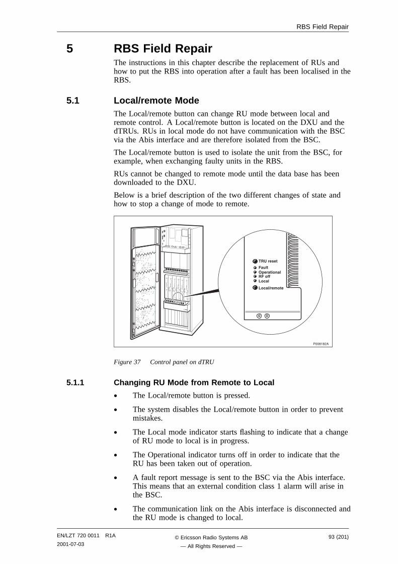
RBS Field Repair
5 RBS Field RepairThe instructions in this chapter describe the replacement of RUs andhow to put the RBS into operation after a fault has been localised in theRBS.
5.1 Local/remote ModeThe Local/remote button can change RU mode between local andremote control. A Local/remote button is located on the DXU and thedTRUs. RUs in local mode do not have communication with the BSCvia the Abis interface and are therefore isolated from the BSC.
The Local/remote button is used to isolate the unit from the BSC, forexample, when exchanging faulty units in the RBS.
RUs cannot be changed to remote mode until the data base has beendownloaded to the DXU.
Below is a brief description of the two different changes of state andhow to stop a change of mode to remote.
������,�
���������
��� �����������������
�����������
Figure 37 Control panel on dTRU
5.1.1 Changing RU Mode from Remote to Local
• The Local/remote button is pressed.
• The system disables the Local/remote button in order to preventmistakes.
• The Local mode indicator starts flashing to indicate that a changeof RU mode to local is in progress.
• The Operational indicator turns off in order to indicate that theRU has been taken out of operation.
• A fault report message is sent to the BSC via the Abis interface.This means that an external condition class 1 alarm will arise inthe BSC.
• The communication link on the Abis interface is disconnected andthe RU mode is changed to local.
EN/LZT 720 0011 R1A
2001-07-0393 (201)© Ericsson Radio Systems AB
— All Rights Reserved —
RBS Field Repair
• The indicators RF off and Local mode both turn on. TheOperational indicator is also turned on, if the RU is free fromclass 1 faults, in order to indicate that the RU is in local operation.
• The system enables the Local/remote button again.
5.1.2 Changing RU Mode from Local to Remote
• The Local/remote button is pressed.
• The Local mode indicator starts flashing to indicate that a changeof RU mode to remote is in progress.
• The Operational indicator turns off in order to indicate that theRU has been taken out of operation.
• The communication link on the Abis interface is established byorder from the BSC. The RU is changed to remote modeimmediately after the link towards the BSC has been established.
• The indicators RF off and Local mode both turn off.
• In order to indicate that the RU is ready to carry traffic, theOperational indicator turns on. Note that this will only happen ifthe RU is considered as operational by the BSC. (For example,the unit may be blocked from the BSC.)
5.1.3 Stopping a Change of RU Mode from Local to Remote
If the Local/remote button is pushed while the Local mode indicator isflashing, the change of RU mode to remote is interrupted.
Note: This function is only valid during a change of RU modefrom local to remote.
• The Local/remote button is pressed.
• The attempt to enable a connection with the BSC will stop.
• The RU will then remain in local mode with the communicationlink disconnected and the indicators RF off and Local mode bothremain on.
94 (201) EN/LZT 720 0011 R1A
2001-07-03© Ericsson Radio Systems AB
— All Rights Reserved —
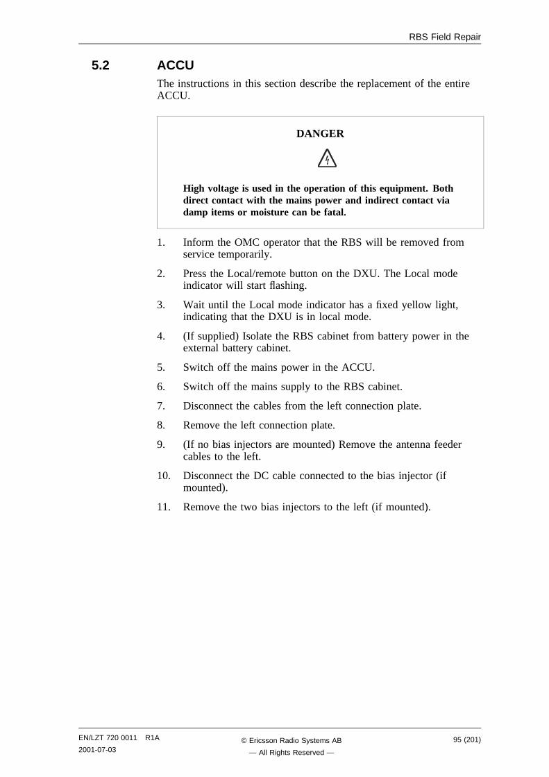
RBS Field Repair
5.2 ACCUThe instructions in this section describe the replacement of the entireACCU.
DANGER
High voltage is used in the operation of this equipment. Bothdirect contact with the mains power and indirect contact viadamp items or moisture can be fatal.
1. Inform the OMC operator that the RBS will be removed fromservice temporarily.
2. Press the Local/remote button on the DXU. The Local modeindicator will start flashing.
3. Wait until the Local mode indicator has a fixed yellow light,indicating that the DXU is in local mode.
4. (If supplied) Isolate the RBS cabinet from battery power in theexternal battery cabinet.
5. Switch off the mains power in the ACCU.
6. Switch off the mains supply to the RBS cabinet.
7. Disconnect the cables from the left connection plate.
8. Remove the left connection plate.
9. (If no bias injectors are mounted) Remove the antenna feedercables to the left.
10. Disconnect the DC cable connected to the bias injector (ifmounted).
11. Remove the two bias injectors to the left (if mounted).
EN/LZT 720 0011 R1A
2001-07-0395 (201)© Ericsson Radio Systems AB
— All Rights Reserved —

RBS Field Repair
����,�-�
�����>� ���
��� ���+���
���
Figure 38 Cables, connection plate and ACCU
12. Remove the ACCU cover plate.
13. Disconnect the AC mains cables from the top of the AC mainsswitch.
96 (201) EN/LZT 720 0011 R1A
2001-07-03© Ericsson Radio Systems AB
— All Rights Reserved —
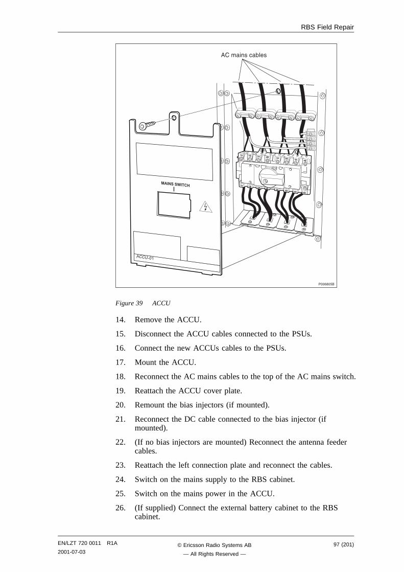
RBS Field Repair
���-��6�
�� �� �� �� �� �� �� ��
�� �� �� �� �� �� �� ��
����������
�������
������� (���
Figure 39 ACCU
14. Remove the ACCU.
15. Disconnect the ACCU cables connected to the PSUs.
16. Connect the new ACCUs cables to the PSUs.
17. Mount the ACCU.
18. Reconnect the AC mains cables to the top of the AC mains switch.
19. Reattach the ACCU cover plate.
20. Remount the bias injectors (if mounted).
21. Reconnect the DC cable connected to the bias injector (ifmounted).
22. (If no bias injectors are mounted) Reconnect the antenna feedercables.
23. Reattach the left connection plate and reconnect the cables.
24. Switch on the mains supply to the RBS cabinet.
25. Switch on the mains power in the ACCU.
26. (If supplied) Connect the external battery cabinet to the RBScabinet.
EN/LZT 720 0011 R1A
2001-07-0397 (201)© Ericsson Radio Systems AB
— All Rights Reserved —
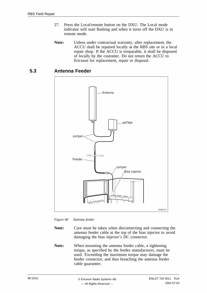
RBS Field Repair
27. Press the Local/remote button on the DXU. The Local modeindicator will start flashing and when it turns off the DXU is inremote mode.
Note: Unless under contractual warranty, after replacement, theACCU shall be repaired locally at the RBS site or in a localrepair shop. If the ACCU is irreparable, it shall be disposedof locally by the customer. Do not return the ACCU toEricsson for replacement, repair or disposal.
5.3 Antenna Feeder
����"���
?#�+��
������
�����
?#�+�������>� ���
���
Figure 40 Antenna feeder
Note: Care must be taken when disconnecting and connecting theantenna feeder cable at the top of the bias injector to avoiddamaging the bias injector’s DC connector.
Note: When mounting the antenna feeder cable, a tighteningtorque, as specified by the feeder manufacturer, must beused. Exceeding the maximum torque may damage thefeeder connector, and thus breaching the antenna feedercable guarantee.
98 (201) EN/LZT 720 0011 R1A
2001-07-03© Ericsson Radio Systems AB
— All Rights Reserved —
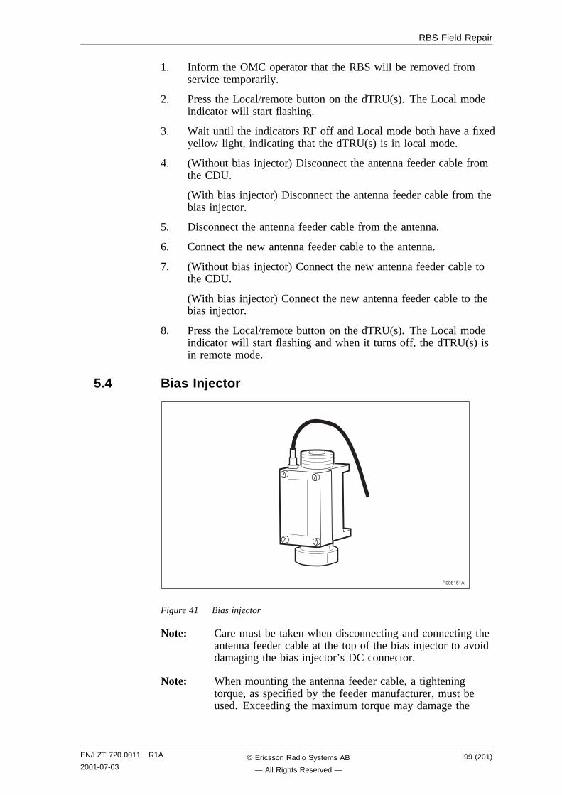
RBS Field Repair
1. Inform the OMC operator that the RBS will be removed fromservice temporarily.
2. Press the Local/remote button on the dTRU(s). The Local modeindicator will start flashing.
3. Wait until the indicators RF off and Local mode both have a fixedyellow light, indicating that the dTRU(s) is in local mode.
4. (Without bias injector) Disconnect the antenna feeder cable fromthe CDU.
(With bias injector) Disconnect the antenna feeder cable from thebias injector.
5. Disconnect the antenna feeder cable from the antenna.
6. Connect the new antenna feeder cable to the antenna.
7. (Without bias injector) Connect the new antenna feeder cable tothe CDU.
(With bias injector) Connect the new antenna feeder cable to thebias injector.
8. Press the Local/remote button on the dTRU(s). The Local modeindicator will start flashing and when it turns off, the dTRU(s) isin remote mode.
5.4 Bias Injector
�����6��
Figure 41 Bias injector
Note: Care must be taken when disconnecting and connecting theantenna feeder cable at the top of the bias injector to avoiddamaging the bias injector’s DC connector.
Note: When mounting the antenna feeder cable, a tighteningtorque, as specified by the feeder manufacturer, must beused. Exceeding the maximum torque may damage the
EN/LZT 720 0011 R1A
2001-07-0399 (201)© Ericsson Radio Systems AB
— All Rights Reserved —
RBS Field Repair
feeder connector, and thus breaching the antenna feedercable guarantee.
1. Inform the OMC operator that a bias injector will be replaced.
2. Press the Local/remote button on the dTRUs that are connected tothe faulty bias injector. The Local mode indicator will startflashing.
3. Wait until the indicators RF off and Local mode both have a fixedyellow light, indicating that the dTRUs are in local mode.
4. Disconnect the DC cable connected to the bias injector.
5. Disconnect the antenna feeder cable connected to the bias injector.
6. Replace the faulty bias injector.
7. Reconnect the antenna feeder cable to the new bias injector.
8. Reconnect the DC cable to the bias injector.
9. Press the Local/remote button on the dTRUs. The Local modeindicator will start flashing and when it turns off the dTRUs are inremote mode.
5.5 CDUNote: CDUs are marked on the front with a label showing the
frequency. Make sure that the appropriate CDU is available.
100 (201) EN/LZT 720 0011 R1A
2001-07-03© Ericsson Radio Systems AB
— All Rights Reserved —
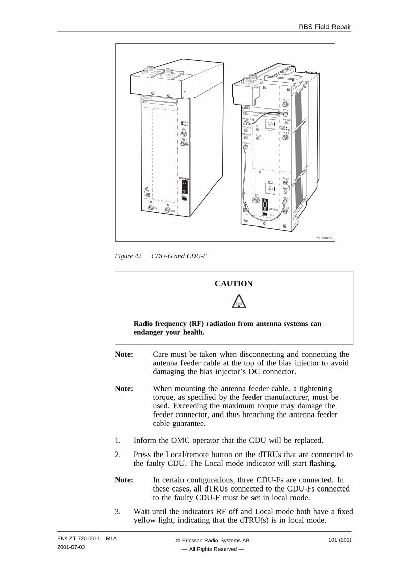
RBS Field Repair
���,@,
���!��-�
���
�� /�
�� /A���
�#��1+��
�� �(#��� �(#�
����
�����,
���
��,
�#��1+��
�����,
������
����@�
����@,
���,@�
������
�����,
���,
��
�� �(#�
����
����#��,
����#���
����#��,
����#���
����
���,
����
������
������
Figure 42 CDU-G and CDU-F
CAUTION
Radio frequency (RF) radiation from antenna systems canendanger your health.
Note: Care must be taken when disconnecting and connecting theantenna feeder cable at the top of the bias injector to avoiddamaging the bias injector’s DC connector.
Note: When mounting the antenna feeder cable, a tighteningtorque, as specified by the feeder manufacturer, must beused. Exceeding the maximum torque may damage thefeeder connector, and thus breaching the antenna feedercable guarantee.
1. Inform the OMC operator that the CDU will be replaced.
2. Press the Local/remote button on the dTRUs that are connected tothe faulty CDU. The Local mode indicator will start flashing.
Note: In certain configurations, three CDU-Fs are connected. Inthese cases, all dTRUs connected to the CDU-Fs connectedto the faulty CDU-F must be set in local mode.
3. Wait until the indicators RF off and Local mode both have a fixedyellow light, indicating that the dTRU(s) is in local mode.
EN/LZT 720 0011 R1A
2001-07-03101 (201)© Ericsson Radio Systems AB
— All Rights Reserved —
RBS Field Repair
4. Switch off the circuit breaker CDU 1, CDU 2 or CDU 3.
Note: To prevent damage to TRUs and exposure to RF radiation,be sure that the indicators RF off and Local mode on theTRUs, that are connected to the faulty CDU, all have afixed yellow light before taking any further actions.
5. (With bias injectors) Remove the bias injectors connected to thefaulty CDU. See Section 5.4 Bias Injector on page 99.
(Without bias injectors) Remove the antenna feeder cables.
6. Disconnect all cables connected to the faulty CDU.
7. If the CDU is equipped with a CNU, move the CNU to the newCDU. See instructions in Section 5.9 CNU on page 106.
8. Replace the CDU.
9. (With bias injectors) Reattach the bias injectors.
(Without bias injectors) Reconnect the antenna feeder cables.
10. Reconnect all cables.
11. Switch on the circuit breaker CDU 1, CDU 2 or CDU 3.
12. Press DXU Reset on the DXU. The RU information from the newCDU will then be loaded into the RBS data base.
13. Press the Local/remote buttons on both dTRUs that are connectedto the new CDU. The Local mode indicator will start flashing andwhen it turns off the dTRUs are in remote mode.
Note: If baseband hopping is used, the hopping sequence can onlybe re-initiated by the BSC/MSC. After placing a dTRU inremote mode, contact the BSC/MSC and request they takethe required action.
Note: After replacement, the CDU must be returned to Ericssonfor repair. Maintenance personnel must attach a repairdelivery note, LZF 084 64 (Blue Tag), to the CDU. Therepair delivery note must include a clear description of thefault found. See the chapter Concluding Routines forinstructions on completing a repair deliver note.
5.6 CDU Bus1. Press the Local/remote button on the dTRU(s). The Local mode
indicator will start flashing.
2. Wait until the indicators RF off and Local mode both have a fixedyellow light, indicating that the dTRU(s) is in local mode.
3. Disconnect the CDU Bus cable attached to the CDU.
4. Connect the new CDU Bus cable to the CDU.
5. Remove the IDM.
6. Remove the dTRU.
102 (201) EN/LZT 720 0011 R1A
2001-07-03© Ericsson Radio Systems AB
— All Rights Reserved —
RBS Field Repair
7. Disconnect the CDU Bus cable attached to the TRU backplane.
8. Connect the new CDU Bus cable to the TRU backplane.
9. Mount the dTRU and the IDM.
10. Press the Local/remote button on the dTRU(s). The Local modeindicator will start flashing and when it turns off, the dTRU(s) isin remote mode.
EN/LZT 720 0011 R1A
2001-07-03103 (201)© Ericsson Radio Systems AB
— All Rights Reserved —
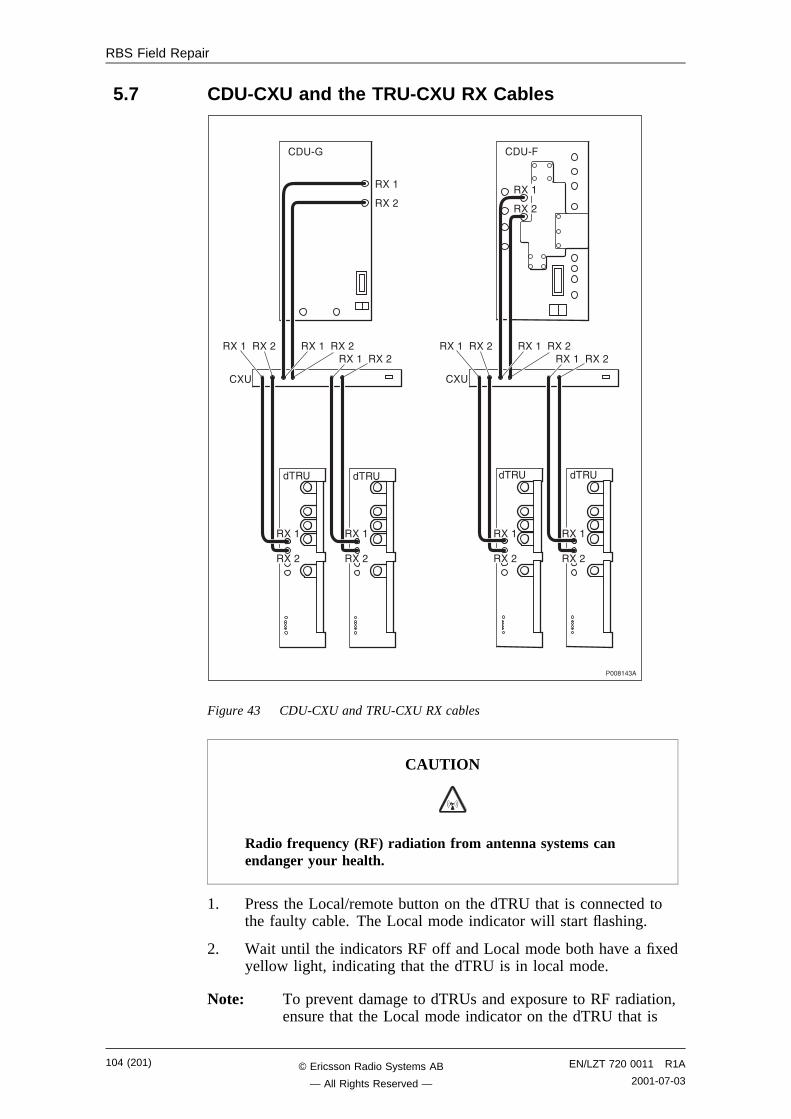
RBS Field Repair
5.7 CDU-CXU and the TRU-CXU RX Cables
������"�
��
���
�� /A
���
��
���
�� /�
���
����
���,����
���,
����
���,
����
���,
����
���,
����
���,
���������, ���������,���������,
���������, ���������,���������,
Figure 43 CDU-CXU and TRU-CXU RX cables
CAUTION
Radio frequency (RF) radiation from antenna systems canendanger your health.
1. Press the Local/remote button on the dTRU that is connected tothe faulty cable. The Local mode indicator will start flashing.
2. Wait until the indicators RF off and Local mode both have a fixedyellow light, indicating that the dTRU is in local mode.
Note: To prevent damage to dTRUs and exposure to RF radiation,ensure that the Local mode indicator on the dTRU that is
104 (201) EN/LZT 720 0011 R1A
2001-07-03© Ericsson Radio Systems AB
— All Rights Reserved —
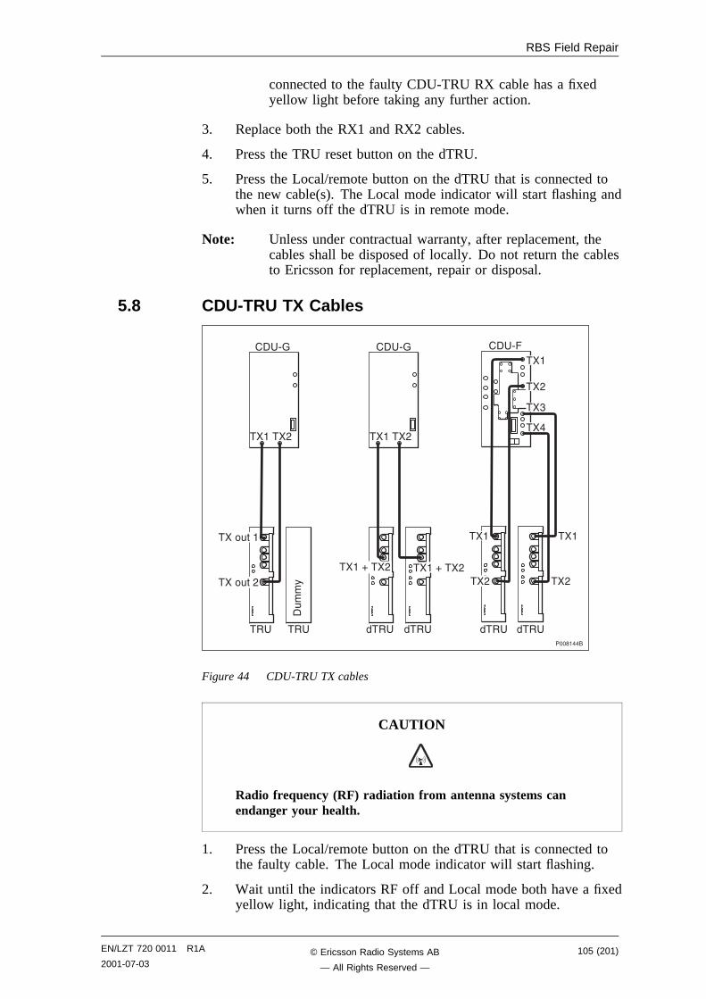
RBS Field Repair
connected to the faulty CDU-TRU RX cable has a fixedyellow light before taking any further action.
3. Replace both the RX1 and RX2 cables.
4. Press the TRU reset button on the dTRU.
5. Press the Local/remote button on the dTRU that is connected tothe new cable(s). The Local mode indicator will start flashing andwhen it turns off the dTRU is in remote mode.
Note: Unless under contractual warranty, after replacement, thecables shall be disposed of locally. Do not return the cablesto Ericsson for replacement, repair or disposal.
5.8 CDU-TRU TX Cables
��������
��
�#�
�%
�� /A �� /A �� /�
��� ��, ��� ��,
���
��,
��"
���
�� ��� ��� ��� ���
����#���
����#��,����B���, ����B���,
��� ���
��, ��,
Figure 44 CDU-TRU TX cables
CAUTION
Radio frequency (RF) radiation from antenna systems canendanger your health.
1. Press the Local/remote button on the dTRU that is connected tothe faulty cable. The Local mode indicator will start flashing.
2. Wait until the indicators RF off and Local mode both have a fixedyellow light, indicating that the dTRU is in local mode.
EN/LZT 720 0011 R1A
2001-07-03105 (201)© Ericsson Radio Systems AB
— All Rights Reserved —
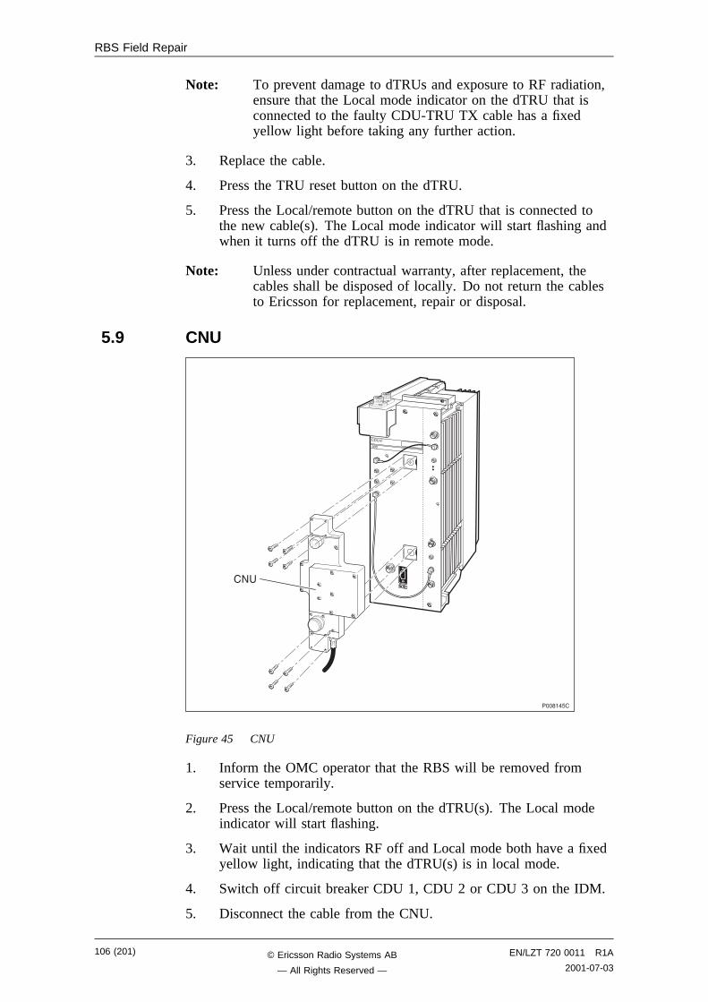
RBS Field Repair
Note: To prevent damage to dTRUs and exposure to RF radiation,ensure that the Local mode indicator on the dTRU that isconnected to the faulty CDU-TRU TX cable has a fixedyellow light before taking any further action.
3. Replace the cable.
4. Press the TRU reset button on the dTRU.
5. Press the Local/remote button on the dTRU that is connected tothe new cable(s). The Local mode indicator will start flashing andwhen it turns off the dTRU is in remote mode.
Note: Unless under contractual warranty, after replacement, thecables shall be disposed of locally. Do not return the cablesto Ericsson for replacement, repair or disposal.
5.9 CNU
������6�
���
�� /�
�8
Figure 45 CNU
1. Inform the OMC operator that the RBS will be removed fromservice temporarily.
2. Press the Local/remote button on the dTRU(s). The Local modeindicator will start flashing.
3. Wait until the indicators RF off and Local mode both have a fixedyellow light, indicating that the dTRU(s) is in local mode.
4. Switch off circuit breaker CDU 1, CDU 2 or CDU 3 on the IDM.
5. Disconnect the cable from the CNU.
106 (201) EN/LZT 720 0011 R1A
2001-07-03© Ericsson Radio Systems AB
— All Rights Reserved —
RBS Field Repair
6. Remove the CNU by unscrewing the eight screws. See figureabove.
7. Attach the new CNU to the CDU-F and tighten the eight screws.
8. Connect the cable from the CNU to the CDU.
9. Switch on circuit breaker CDU 1, CDU 2 or CDU 3 on the IDM.
10. Press the Local/remote button on the dTRU(s). The Local modeindicator will start flashing and when it turns off, the dTRU(s) isin remote mode.
5.10 CXU1. Inform the OMC operator that the RBS will be removed from
service temporarily.
2. Press the Local/remote button on the DXU. The Local modeindicator will start flashing.
3. Wait until the Local mode indicator has a fixed yellow light,indicating that the DXU is in local mode.
4. Switch off circuit breaker CXU1–2 on the IDM.
5. Remove all cables connected to the CXU.
6. Replace the CXU and reconnect the disconnected cables.
7. Switch on circuit breaker CXU1–2 on the IDM.
8. Press the Local/remote button on the DXU. The Local modeindicator will start flashing.
9. When the Local mode indicator is turned off, the DXU is inremote mode.
10. Check that the RBS fault indicator (DXU) is off. This means thatthere are no active faults in the RBS.
EN/LZT 720 0011 R1A
2001-07-03107 (201)© Ericsson Radio Systems AB
— All Rights Reserved —
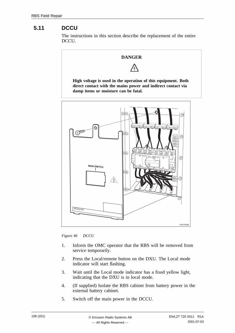
RBS Field Repair
5.11 DCCUThe instructions in this section describe the replacement of the entireDCCU.
DANGER
High voltage is used in the operation of this equipment. Bothdirect contact with the mains power and indirect contact viadamp items or moisture can be fatal.
���!6���
�� �� �� �� �� �� �� ��
�� �� �� �� �� �� �� ��
���������
�������
Figure 46 DCCU
1. Inform the OMC operator that the RBS will be removed fromservice temporarily.
2. Press the Local/remote button on the DXU. The Local modeindicator will start flashing.
3. Wait until the Local mode indicator has a fixed yellow light,indicating that the DXU is in local mode.
4. (If supplied) Isolate the RBS cabinet from battery power in theexternal battery cabinet.
5. Switch off the main power in the DCCU.
108 (201) EN/LZT 720 0011 R1A
2001-07-03© Ericsson Radio Systems AB
— All Rights Reserved —

RBS Field Repair
6. Switch off the mains supply to the RBS cabinet.
7. Disconnect the cables from the left connection plate.
8. Remove the connection plate.
9. (If no bias injectors are mounted) Remove the antenna feedercables to the left.
10. Disconnect the DC cable connected to the bias injector (ifmounted).
11. Remove the two bias injectors to the left (if mounted).
12. Remove the DCCU cover plate.
13. Disconnect the DC supply cables from the top of the DC mainswitch.
14. Remove the DCCU.
15. Disconnect the DCCU cables connected to the PSUs.
16. Connect the new DCCUs cables to the PSUs.
17. Mount the new DCCU.
18. Reconnect the DC supply cables to the top of the DC main switch.
19. Reattach the DCCU cover plate.
20. Remount the bias injectors (if mounted).
21. Reconnect the DC cable connected to the bias injector (ifmounted).
22. (If no bias injectors are mounted) Reconnect the antenna feedercables.
23. Reattach the connection plate and reconnect the cables.
24. Switch on the mains supply to the RBS cabinet.
25. Switch on the main power in the DCCU.
26. (If supplied) Connect the external battery cabinet to the RBScabinet.
27. Press the Local/remote button on the DXU. The Local modeindicator will start flashing and when it turns off the DXU is inremote mode.
5.12 DC FilterNote: These instructions are valid only for cabinets equipped with
external batteries.
EN/LZT 720 0011 R1A
2001-07-03109 (201)© Ericsson Radio Systems AB
— All Rights Reserved —
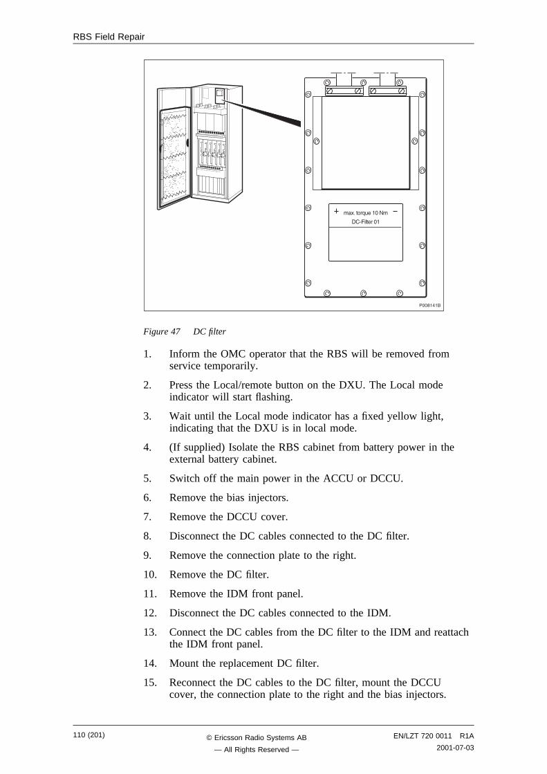
RBS Field Repair
��������
�*C����;#�����8�
��/���������
Figure 47 DC filter
1. Inform the OMC operator that the RBS will be removed fromservice temporarily.
2. Press the Local/remote button on the DXU. The Local modeindicator will start flashing.
3. Wait until the Local mode indicator has a fixed yellow light,indicating that the DXU is in local mode.
4. (If supplied) Isolate the RBS cabinet from battery power in theexternal battery cabinet.
5. Switch off the main power in the ACCU or DCCU.
6. Remove the bias injectors.
7. Remove the DCCU cover.
8. Disconnect the DC cables connected to the DC filter.
9. Remove the connection plate to the right.
10. Remove the DC filter.
11. Remove the IDM front panel.
12. Disconnect the DC cables connected to the IDM.
13. Connect the DC cables from the DC filter to the IDM and reattachthe IDM front panel.
14. Mount the replacement DC filter.
15. Reconnect the DC cables to the DC filter, mount the DCCUcover, the connection plate to the right and the bias injectors.
110 (201) EN/LZT 720 0011 R1A
2001-07-03© Ericsson Radio Systems AB
— All Rights Reserved —
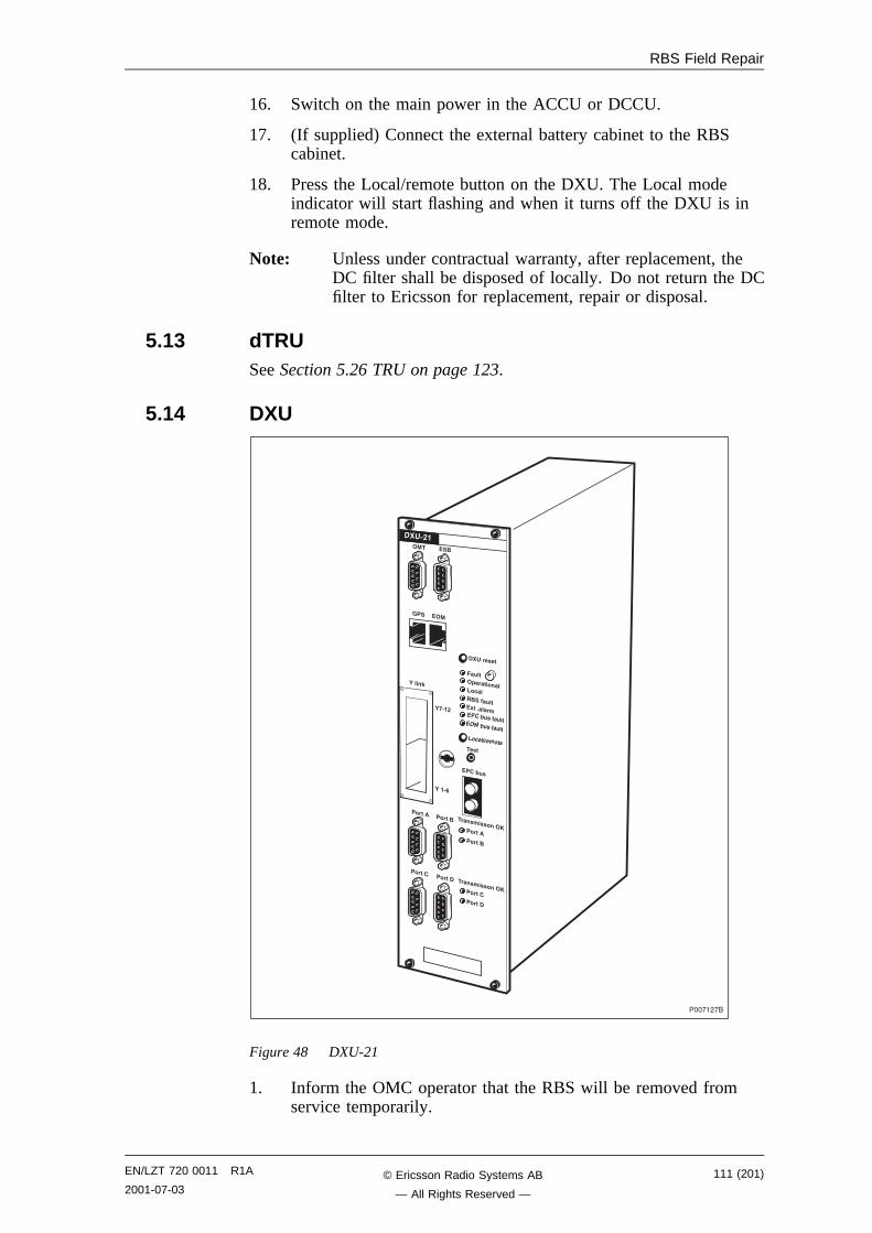
RBS Field Repair
16. Switch on the main power in the ACCU or DCCU.
17. (If supplied) Connect the external battery cabinet to the RBScabinet.
18. Press the Local/remote button on the DXU. The Local modeindicator will start flashing and when it turns off the DXU is inremote mode.
Note: Unless under contractual warranty, after replacement, theDC filter shall be disposed of locally. Do not return the DCfilter to Ericsson for replacement, repair or disposal.
5.13 dTRUSee Section 5.26 TRU on page 123.
5.14 DXU
���!�,!�
���������
��� ������������
� !�"�������� #�"�������
��$������%��&���
���������������
� !�"��
���'��
����� �����
����� �����
����� ����!
#� �$�
( $ � #
)*'��
)��'+
����������� , ����! �����
����������� ,
)����-
Figure 48 DXU-21
1. Inform the OMC operator that the RBS will be removed fromservice temporarily.
EN/LZT 720 0011 R1A
2001-07-03111 (201)© Ericsson Radio Systems AB
— All Rights Reserved —
RBS Field Repair
2. Press the Local/remote button on the DXU. The Local modeindicator will start flashing.
3. Wait until Local mode indicator has a fixed yellow light,indicating that the DXU is in local mode.
4. Switch off circuit breaker DXU/Sys.volt.sens on the IDM.
5. Remove all cables connected to the DXU.
6. Remove the Flash Card from DXU and place it in the new DXUbefore sending the DXU to the Repair Centre.
Note: If the Flash Card is faulty, reload the IDB. See Section 5.19Flash Card on page 117.
7. Replace the DXU and reconnect the disconnected cables.
8. Switch on circuit breaker DXU/Sys.volt.sens on the IDM.
9. Press the DXU reset button on the DXU. This will distribute theIDB to the RUs.
10. Wait until the Operational indicator on the new DXU has a fixedgreen light.
11. Press the Local/remote button on the new DXU. The Local/remotebutton will start flashing and when it turns off, the DXU is inremote mode.
12. Make a request to the OMC operator to check that all MOs areoperational.
Note: After replacement, the DXU must be returned to Ericssonfor repair. Maintenance personnel must attach a repairdelivery note, LZF 084 64 (Blue Tag), to the DXU. Therepair delivery note must include a clear description of thefault found. See chapter Concluding Routines forinstructions on completing a repair delivery note.
5.15 DXU BackplaneNote: When changing the DXU backplane, see chapter Cable
Connections. Note the position of RUs within the originalsub-rack, so that they can be replaced into the correctposition without changing the IDB.
112 (201) EN/LZT 720 0011 R1A
2001-07-03© Ericsson Radio Systems AB
— All Rights Reserved —
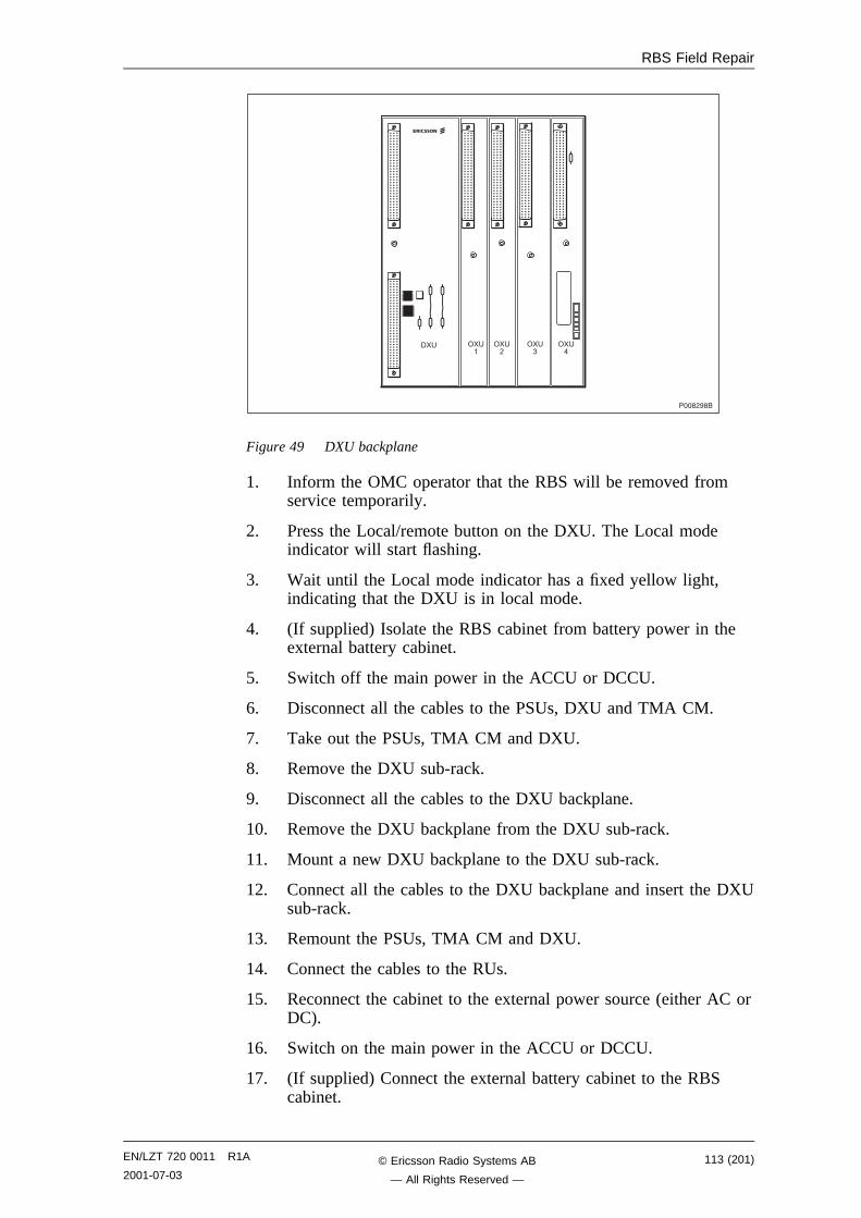
RBS Field Repair
����,���
��� ���
��
���
���
Figure 49 DXU backplane
1. Inform the OMC operator that the RBS will be removed fromservice temporarily.
2. Press the Local/remote button on the DXU. The Local modeindicator will start flashing.
3. Wait until the Local mode indicator has a fixed yellow light,indicating that the DXU is in local mode.
4. (If supplied) Isolate the RBS cabinet from battery power in theexternal battery cabinet.
5. Switch off the main power in the ACCU or DCCU.
6. Disconnect all the cables to the PSUs, DXU and TMA CM.
7. Take out the PSUs, TMA CM and DXU.
8. Remove the DXU sub-rack.
9. Disconnect all the cables to the DXU backplane.
10. Remove the DXU backplane from the DXU sub-rack.
11. Mount a new DXU backplane to the DXU sub-rack.
12. Connect all the cables to the DXU backplane and insert the DXUsub-rack.
13. Remount the PSUs, TMA CM and DXU.
14. Connect the cables to the RUs.
15. Reconnect the cabinet to the external power source (either AC orDC).
16. Switch on the main power in the ACCU or DCCU.
17. (If supplied) Connect the external battery cabinet to the RBScabinet.
EN/LZT 720 0011 R1A
2001-07-03113 (201)© Ericsson Radio Systems AB
— All Rights Reserved —
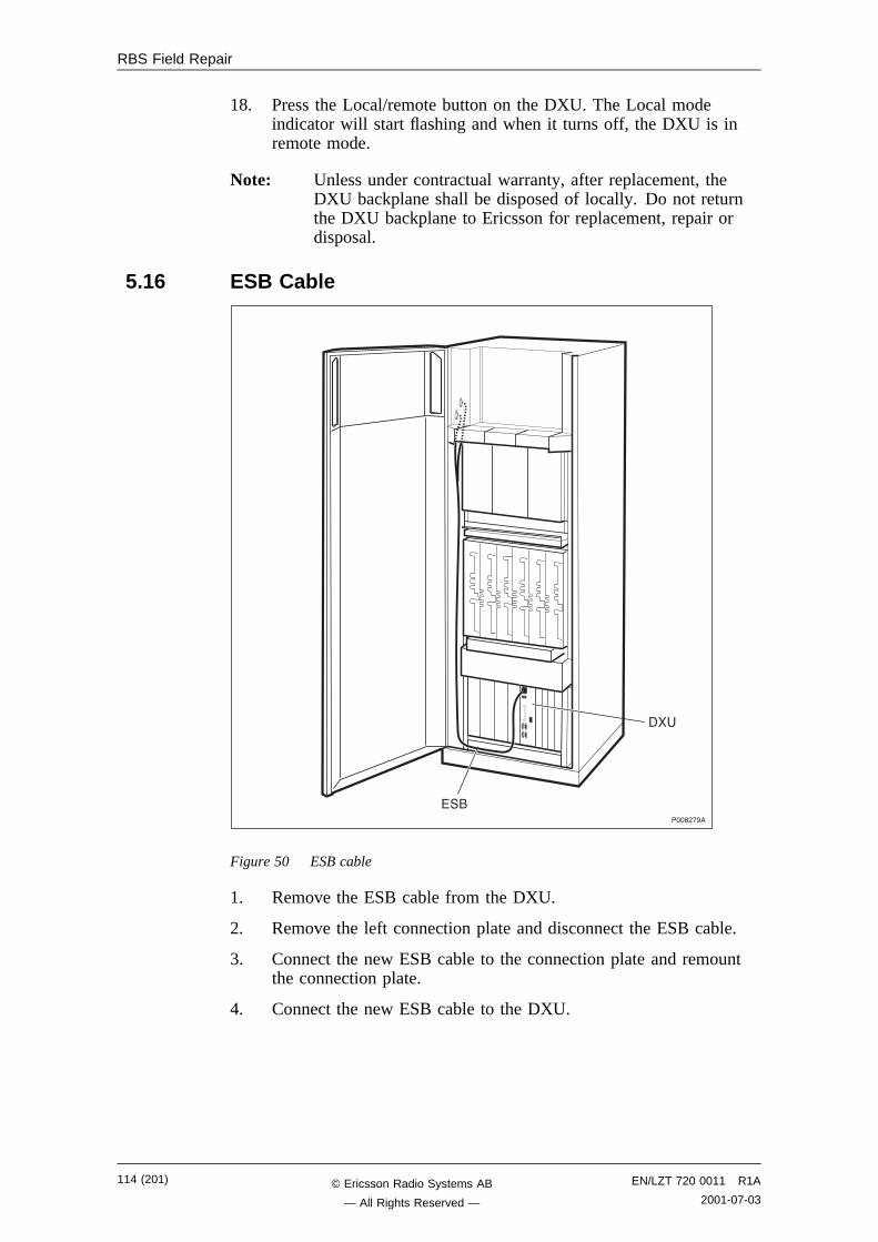
RBS Field Repair
18. Press the Local/remote button on the DXU. The Local modeindicator will start flashing and when it turns off, the DXU is inremote mode.
Note: Unless under contractual warranty, after replacement, theDXU backplane shall be disposed of locally. Do not returnthe DXU backplane to Ericsson for replacement, repair ordisposal.
5.16 ESB Cable
����,!��
��
)��
Figure 50 ESB cable
1. Remove the ESB cable from the DXU.
2. Remove the left connection plate and disconnect the ESB cable.
3. Connect the new ESB cable to the connection plate and remountthe connection plate.
4. Connect the new ESB cable to the DXU.
114 (201) EN/LZT 720 0011 R1A
2001-07-03© Ericsson Radio Systems AB
— All Rights Reserved —
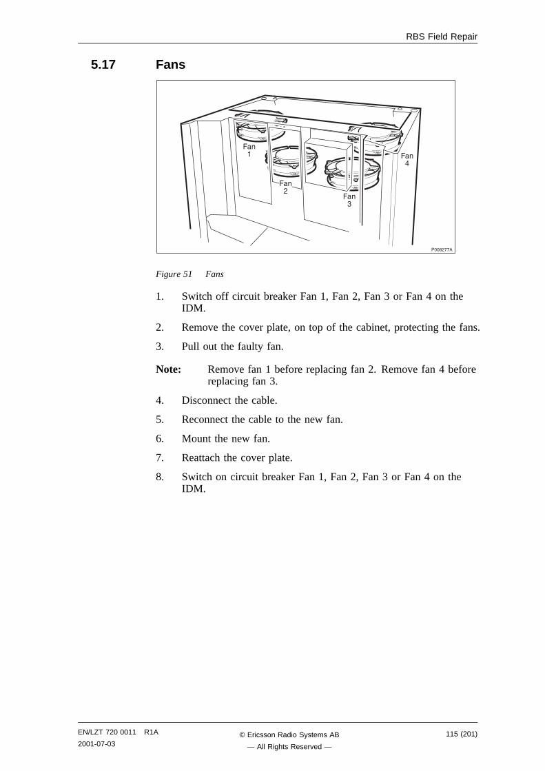
RBS Field Repair
5.17 Fans
����,!!�
��
�,
�"
��
Figure 51 Fans
1. Switch off circuit breaker Fan 1, Fan 2, Fan 3 or Fan 4 on theIDM.
2. Remove the cover plate, on top of the cabinet, protecting the fans.
3. Pull out the faulty fan.
Note: Remove fan 1 before replacing fan 2. Remove fan 4 beforereplacing fan 3.
4. Disconnect the cable.
5. Reconnect the cable to the new fan.
6. Mount the new fan.
7. Reattach the cover plate.
8. Switch on circuit breaker Fan 1, Fan 2, Fan 3 or Fan 4 on theIDM.
EN/LZT 720 0011 R1A
2001-07-03115 (201)© Ericsson Radio Systems AB
— All Rights Reserved —
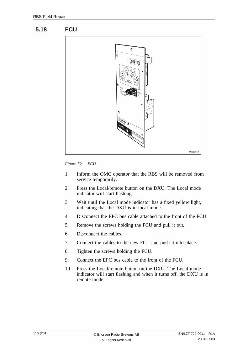
RBS Field Repair
5.18 FCU
����,-6�
Figure 52 FCU
1. Inform the OMC operator that the RBS will be removed fromservice temporarily.
2. Press the Local/remote button on the DXU. The Local modeindicator will start flashing.
3. Wait until the Local mode indicator has a fixed yellow light,indicating that the DXU is in local mode.
4. Disconnect the EPC bus cable attached to the front of the FCU.
5. Remove the screws holding the FCU and pull it out.
6. Disconnect the cables.
7. Connect the cables to the new FCU and push it into place.
8. Tighten the screws holding the FCU.
9. Connect the EPC bus cable to the front of the FCU.
10. Press the Local/remote button on the DXU. The Local modeindicator will start flashing and when it turns off, the DXU is inremote mode.
116 (201) EN/LZT 720 0011 R1A
2001-07-03© Ericsson Radio Systems AB
— All Rights Reserved —
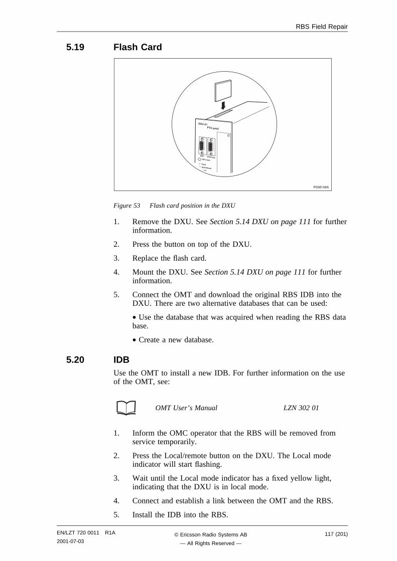
RBS Field Repair
5.19 Flash Card
��������
����
! �������
��� ��������
���'�� �������
#� $).!�"��
Figure 53 Flash card position in the DXU
1. Remove the DXU. See Section 5.14 DXU on page 111 for furtherinformation.
2. Press the button on top of the DXU.
3. Replace the flash card.
4. Mount the DXU. See Section 5.14 DXU on page 111 for furtherinformation.
5. Connect the OMT and download the original RBS IDB into theDXU. There are two alternative databases that can be used:
• Use the database that was acquired when reading the RBS database.
• Create a new database.
5.20 IDBUse the OMT to install a new IDB. For further information on the useof the OMT, see:
OMT User’s Manual LZN 302 01
1. Inform the OMC operator that the RBS will be removed fromservice temporarily.
2. Press the Local/remote button on the DXU. The Local modeindicator will start flashing.
3. Wait until the Local mode indicator has a fixed yellow light,indicating that the DXU is in local mode.
4. Connect and establish a link between the OMT and the RBS.
5. Install the IDB into the RBS.
EN/LZT 720 0011 R1A
2001-07-03117 (201)© Ericsson Radio Systems AB
— All Rights Reserved —
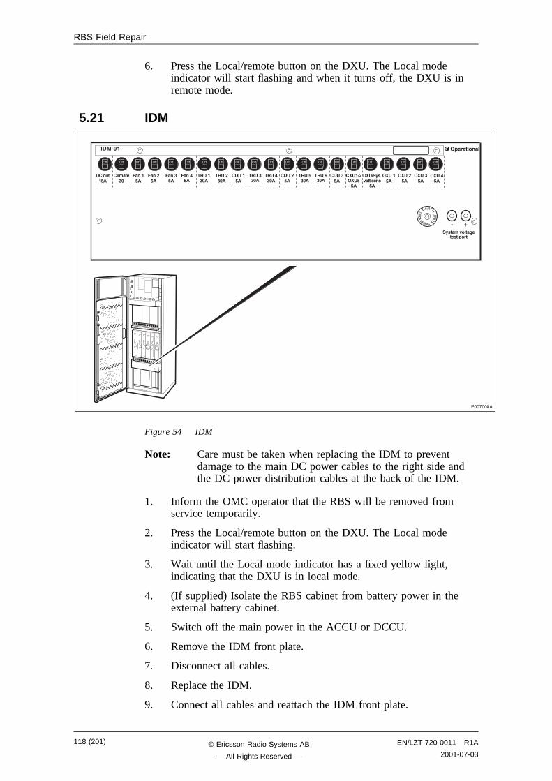
RBS Field Repair
6. Press the Local/remote button on the DXU. The Local modeindicator will start flashing and when it turns off, the DXU is inremote mode.
5.21 IDM
���!����
$/�����0���1����������
�!�����2�
!������3
���2�
���2�
���2�
������3�
������3�
!����2�
����2�3�
!����2�
!���'� ��22�
����2�
!����2�
��������4�#'3�
���2�
������3�
������3�
����+�3�
����$/�&0���&����2�
����2�
����2�
����2�
/ B
)���5
�1�8�
A�1 8��8A
Figure 54 IDM
Note: Care must be taken when replacing the IDM to preventdamage to the main DC power cables to the right side andthe DC power distribution cables at the back of the IDM.
1. Inform the OMC operator that the RBS will be removed fromservice temporarily.
2. Press the Local/remote button on the DXU. The Local modeindicator will start flashing.
3. Wait until the Local mode indicator has a fixed yellow light,indicating that the DXU is in local mode.
4. (If supplied) Isolate the RBS cabinet from battery power in theexternal battery cabinet.
5. Switch off the main power in the ACCU or DCCU.
6. Remove the IDM front plate.
7. Disconnect all cables.
8. Replace the IDM.
9. Connect all cables and reattach the IDM front plate.
118 (201) EN/LZT 720 0011 R1A
2001-07-03© Ericsson Radio Systems AB
— All Rights Reserved —
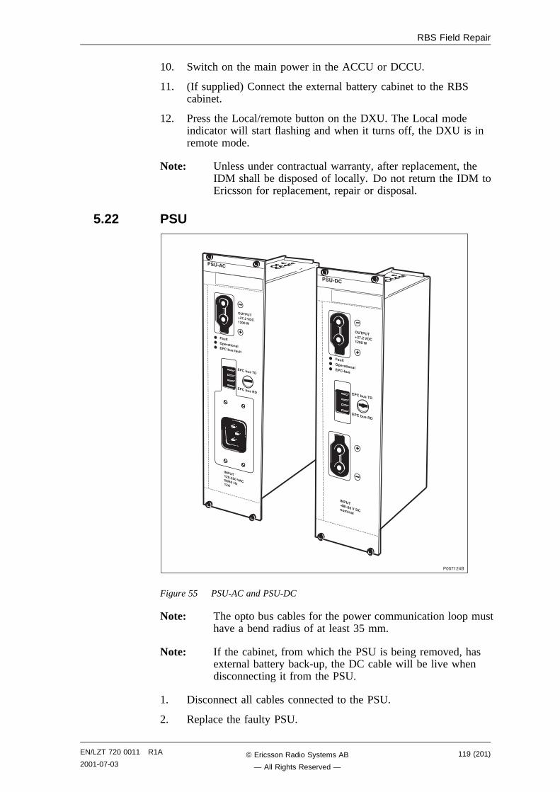
RBS Field Repair
10. Switch on the main power in the ACCU or DCCU.
11. (If supplied) Connect the external battery cabinet to the RBScabinet.
12. Press the Local/remote button on the DXU. The Local modeindicator will start flashing and when it turns off, the DXU is inremote mode.
Note: Unless under contractual warranty, after replacement, theIDM shall be disposed of locally. Do not return the IDM toEricsson for replacement, repair or disposal.
5.22 PSU
4. ����3'�23�5�!23�+3�67���
��� ��������� !�"�������
$�'�!
� !�"�����
� !�"�����
�� ��8�*&��5�!��33�9
���!�,��
��� ��������� !'"��
4. ��'�:�'+3�5��!������
$�'�!
�� ��8�*&��5�!��33�9
� !�"�����
� !�"�����
Figure 55 PSU-AC and PSU-DC
Note: The opto bus cables for the power communication loop musthave a bend radius of at least 35 mm.
Note: If the cabinet, from which the PSU is being removed, hasexternal battery back-up, the DC cable will be live whendisconnecting it from the PSU.
1. Disconnect all cables connected to the PSU.
2. Replace the faulty PSU.
EN/LZT 720 0011 R1A
2001-07-03119 (201)© Ericsson Radio Systems AB
— All Rights Reserved —
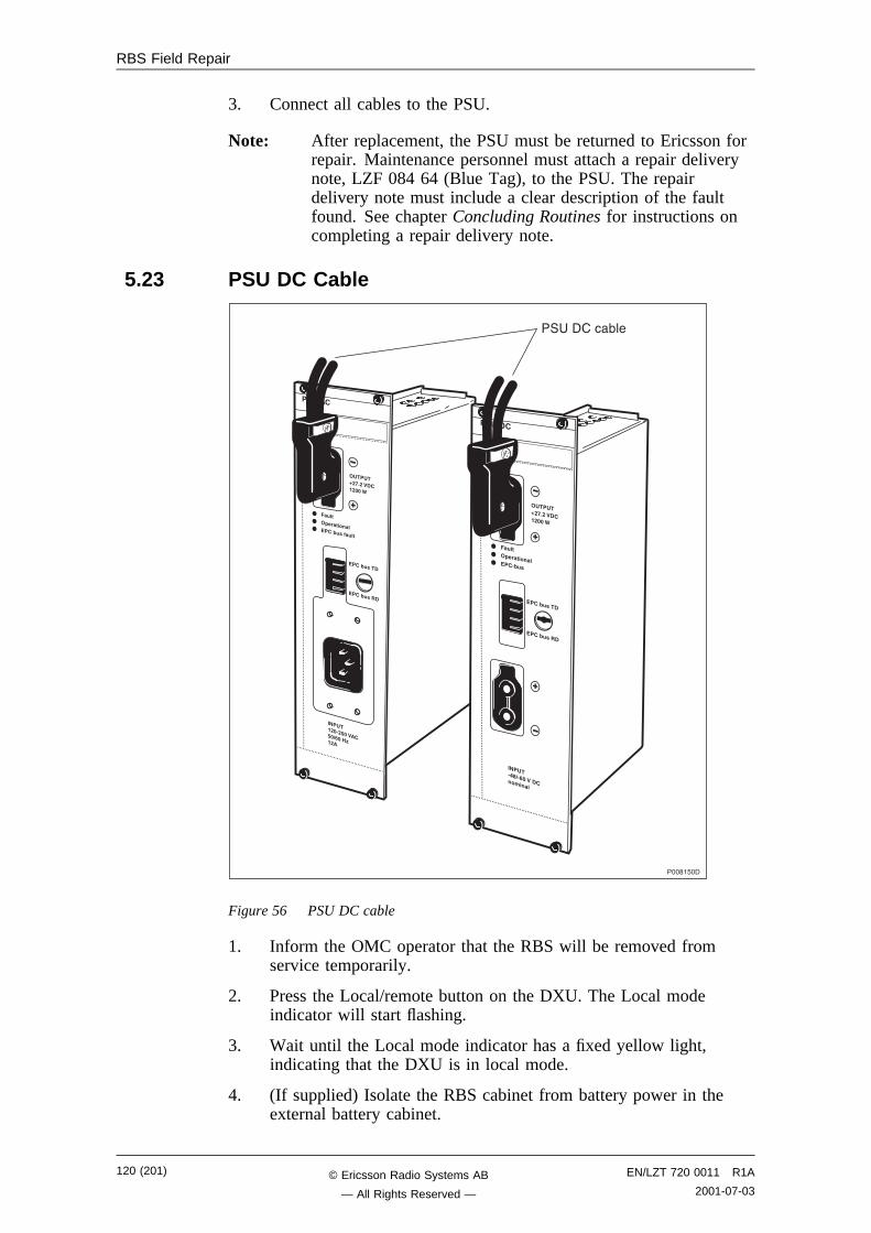
RBS Field Repair
3. Connect all cables to the PSU.
Note: After replacement, the PSU must be returned to Ericsson forrepair. Maintenance personnel must attach a repair deliverynote, LZF 084 64 (Blue Tag), to the PSU. The repairdelivery note must include a clear description of the faultfound. See chapter Concluding Routines for instructions oncompleting a repair delivery note.
5.23 PSU DC Cable
4. ����3'�23�5�!23�+3�67���
��� ��������� !�"�������
$�'�!
� !�"�����
� !�"�����
�� ��8�*&��5�!��33�9
�����6��
��� ��������� !'"��
4. ��'�:�'+3�5��!������
$�'�!
�� ��8�*&��5�!��33�9
� !�"�����
� !�"�����
�� ���� (��
Figure 56 PSU DC cable
1. Inform the OMC operator that the RBS will be removed fromservice temporarily.
2. Press the Local/remote button on the DXU. The Local modeindicator will start flashing.
3. Wait until the Local mode indicator has a fixed yellow light,indicating that the DXU is in local mode.
4. (If supplied) Isolate the RBS cabinet from battery power in theexternal battery cabinet.
120 (201) EN/LZT 720 0011 R1A
2001-07-03© Ericsson Radio Systems AB
— All Rights Reserved —
RBS Field Repair
5. Switch off the main power in the ACCU or DCCU.
6. Disconnect the DC cable connected to the PSU.
7. Remove the IDM.
8. Disconnect the DC cable connected to the back of the IDM.
9. Connect the new DC cable to the IDM.
10. Mount the IDM.
11. Connect the DC cable to the PSU.
12. Switch on the main power in the ACCU or DCCU.
13. (If supplied) Connect the external battery cabinet to the RBScabinet.
14. Press the Local/remote button on the DXU. The Local modeindicator will start flashing and when it turns off, the DXU is inremote mode.
5.24 RX Antenna FeederSee Section 5.3 Antenna Feeder on page 98.
EN/LZT 720 0011 R1A
2001-07-03121 (201)© Ericsson Radio Systems AB
— All Rights Reserved —
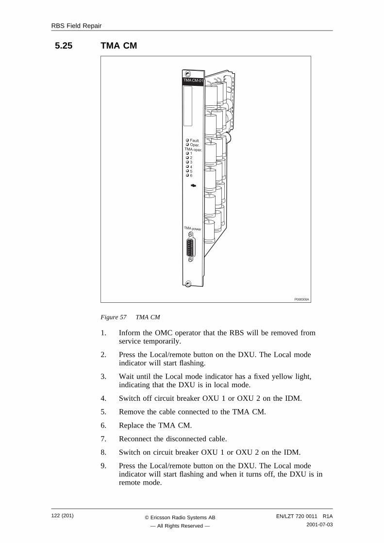
RBS Field Repair
5.25 TMA CM
�������
���������
�����
���������
���������
���������
Figure 57 TMA CM
1. Inform the OMC operator that the RBS will be removed fromservice temporarily.
2. Press the Local/remote button on the DXU. The Local modeindicator will start flashing.
3. Wait until the Local mode indicator has a fixed yellow light,indicating that the DXU is in local mode.
4. Switch off circuit breaker OXU 1 or OXU 2 on the IDM.
5. Remove the cable connected to the TMA CM.
6. Replace the TMA CM.
7. Reconnect the disconnected cable.
8. Switch on circuit breaker OXU 1 or OXU 2 on the IDM.
9. Press the Local/remote button on the DXU. The Local modeindicator will start flashing and when it turns off, the DXU is inremote mode.
122 (201) EN/LZT 720 0011 R1A
2001-07-03© Ericsson Radio Systems AB
— All Rights Reserved —
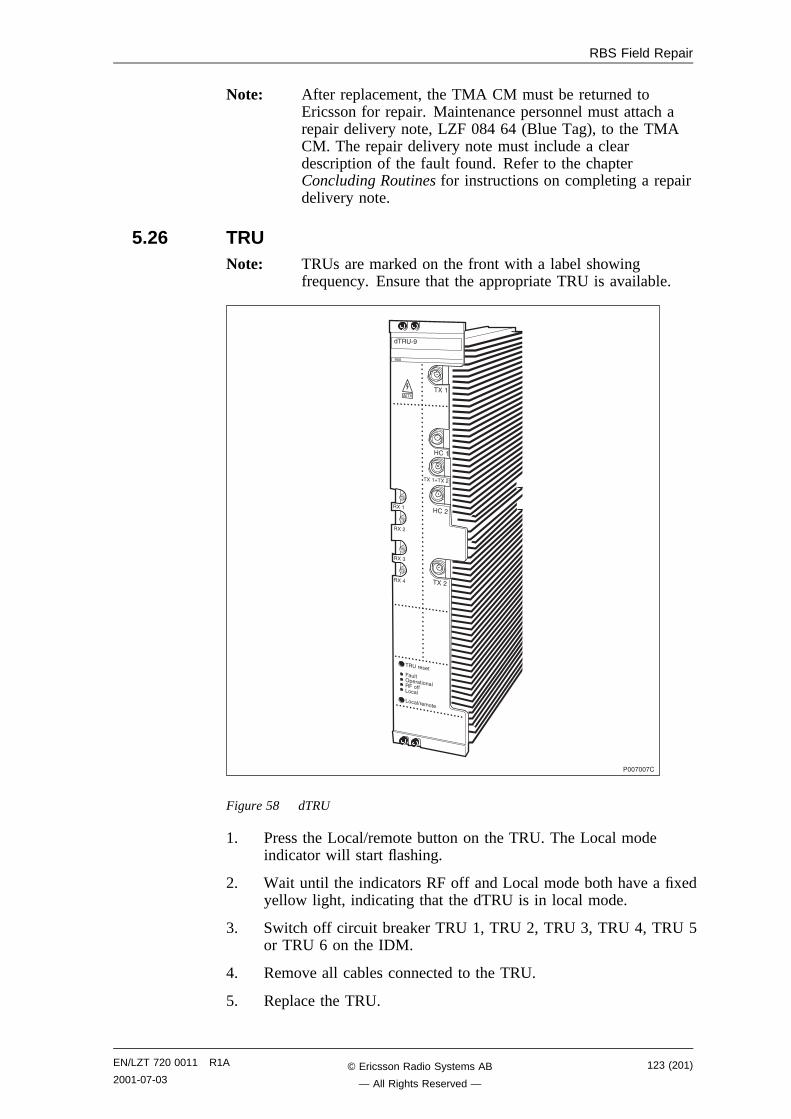
RBS Field Repair
Note: After replacement, the TMA CM must be returned toEricsson for repair. Maintenance personnel must attach arepair delivery note, LZF 084 64 (Blue Tag), to the TMACM. The repair delivery note must include a cleardescription of the fault found. Refer to the chapterConcluding Routines for instructions on completing a repairdelivery note.
5.26 TRUNote: TRUs are marked on the front with a label showing
frequency. Ensure that the appropriate TRU is available.
���!��!�
��� /�
����
5���
����B���,
5��,
���,
����
���,
���"
����
�� ������
���
�#��1+������������.� �
.� �=������
������
Figure 58 dTRU
1. Press the Local/remote button on the TRU. The Local modeindicator will start flashing.
2. Wait until the indicators RF off and Local mode both have a fixedyellow light, indicating that the dTRU is in local mode.
3. Switch off circuit breaker TRU 1, TRU 2, TRU 3, TRU 4, TRU 5or TRU 6 on the IDM.
4. Remove all cables connected to the TRU.
5. Replace the TRU.
EN/LZT 720 0011 R1A
2001-07-03123 (201)© Ericsson Radio Systems AB
— All Rights Reserved —
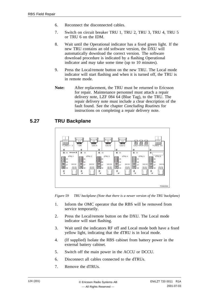
RBS Field Repair
6. Reconnect the disconnected cables.
7. Switch on circuit breaker TRU 1, TRU 2, TRU 3, TRU 4, TRU 5or TRU 6 on the IDM.
8. Wait until the Operational indicator has a fixed green light. If thenew TRU contains an old software version, the DXU willautomatically download the correct version. The softwaredownload procedure is indicated by a flashing Operationalindicator and may take some time (up to 10 minutes).
9. Press the Local/remote button on the new TRU. The Local modeindicator will start flashing and when it is turned off, the TRU isin remote mode.
Note: After replacement, the TRU must be returned to Ericssonfor repair. Maintenance personnel must attach a repairdelivery note, LZF 084 64 (Blue Tag), to the TRU. Therepair delivery note must include a clear description of thefault found. See the chapter Concluding Routines forinstructions on completing a repair delivery note.
5.27 TRU Backplane
:/.�8D���/��" :/.�8D����/-��1� �� /� �� /� �� /� �� � 1� 6 �� ,
��� �-��� �6��� ����� �"��� �,��� ��
�6
�-
�!
��
,�<�<
�6
�-
�!
��
,�<�<
�6
�-
�!
��
,�<�<
�6
�-
�!
��
,�<�<
�6
�-
�!
��
,�<�<
�6
�-
�!
��
,�<�<
�" �" �" �" �"
����,���
Figure 59 TRU backplane (Note that there is a newer version of the TRU backplane)
1. Inform the OMC operator that the RBS will be removed fromservice temporarily.
2. Press the Local/remote button on the DXU. The Local modeindicator will start flashing.
3. Wait until the indicators RF off and Local mode both have a fixedyellow light, indicating that the dTRU is in local mode.
4. (If supplied) Isolate the RBS cabinet from battery power in theexternal battery cabinet.
5. Switch off the main power in the ACCU or DCCU.
6. Disconnect all cables connected to the dTRUs.
7. Remove the dTRUs.
124 (201) EN/LZT 720 0011 R1A
2001-07-03© Ericsson Radio Systems AB
— All Rights Reserved —
RBS Field Repair
8. Disconnect all cables connected to the TRU backplane.
9. Replace the TRU backplane.
10. Connect all the cables to the TRU backplane.
11. Mount all the dTRUs and connect all cables.
12. Switch on the main power in the ACCU or DCCU.
13. (If supplied) Connect the external battery cabinet to the RBScabinet.
14. Press the Local/remote button on the DXU. The Local modeindicator will start flashing and when it turns off, the DXU is inremote mode.
Note: Unless under contractual warranty, after replacement, theTRU backplane shall be disposed of locally. Do not returnthe TRU backplane to Ericsson for replacement, repair ordisposal.
5.28 TX Antenna FeederSee Section 5.3 Antenna Feeder on page 98.
EN/LZT 720 0011 R1A
2001-07-03125 (201)© Ericsson Radio Systems AB
— All Rights Reserved —

RBS Field Repair
This page is intentionally left blank
126 (201) EN/LZT 720 0011 R1A
2001-07-03© Ericsson Radio Systems AB
— All Rights Reserved —
Test after Repair
6 Test after RepairThis chapter describes the methods for verifying the RBS. The intentionis to verify that the problem has been solved and that the RBS is fullyfunctional.
Note: All known faults must be cleared before performing the tests.
6.1 PreconditionsTest calls should be performed with a TEMS using the TEMS Software.
6.2 Test CallTest calls must be made when a CXU, TRU or CDU has been replacedto ensure that the replaced units carry traffic.
If the technican is required to make a test call on a specific RU,information is needed on the ARFCN(s) for each TRU. Contact theBSC personnel for information on ARFCN(s).
The test procedure is divided into two parts, that are done in sequence.The first test sequence of the downlink connection is monitored by theTEMS. The second test sequence of the uplink connection is monitoredby the OMT.
Note: Before starting the test call, the Operational indicators on theDXU and TRUs must be on. Set all units to remote mode.
Monitoring the Dedicated channel with a TEMS
1. Connect the TEMS to the PC serial port.
2. Start the TEMS program in the Windows environment.
3. Select Enable Connections in the Externals menu and specifythe serial port for the TEMS.
4. Contact the BSC personnel to find out which ARFCN and TS thata test call should be performed on.
The BSC personnel can use the printout command:
RXCDP:MO=RXOTG-tg;
Note: The RXCDP gives, for the TG specified, the ARFCN andTN (timeslot number on the air interface) that correspondsto the equipment TS. The TS and TN are normally thesame, but there are exceptions. Therefore always check theTN with RXCDP).
5. Choose Cell Selection in the Control menu.
6. Choose Target frequency and select the ARFCN for the TRUthat is to be tested. Mark the frequency in the list.
7. Disable the Handover button in the Cell Selection menu.
8. Select Status information in the Monitor menu.
9. Choose Dedicated channel.
EN/LZT 720 0011 R1A
2001-07-03127 (201)© Ericsson Radio Systems AB
— All Rights Reserved —
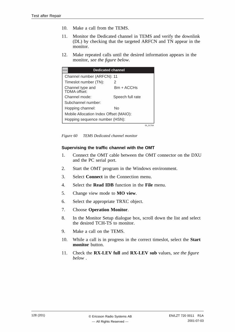
Test after Repair
10. Make a call from the TEMS.
11. Monitor the Dedicated channel in TEMS and verify the downlink(DL) by checking that the targeted ARFCN and TN appear in themonitor.
12. Make repeated calls until the desired information appears in themonitor, see the figure below.
Channel number (ARFCN): 11Timeslot number (TN): 2Channel type and Bm + ACCHsTDMA offset:Channel mode: Speech full rate
Subchannel number:Hopping channel: No
Mobile Allocation Index Offset (MAIO):Hopping sequence number (HSN):
Dedicated channel
06_0178A
Figure 60 TEMS Dedicated channel monitor
Supervising the traffic channel with the OMT
1. Connect the OMT cable between the OMT connector on the DXUand the PC serial port.
2. Start the OMT program in the Windows environment.
3. Select Connect in the Connection menu.
4. Select the Read IDB function in the File menu.
5. Change view mode to MO view.
6. Select the appropriate TRXC object.
7. Choose Operation Monitor.
8. In the Monitor Setup dialogue box, scroll down the list and selectthe desired TCH-TS to monitor.
9. Make a call on the TEMS.
10. While a call is in progress in the correct timeslot, select the Startmonitor button.
11. Check the RX-LEV full and RX-LEV sub values, see the figurebelow .
128 (201) EN/LZT 720 0011 R1A
2001-07-03© Ericsson Radio Systems AB
— All Rights Reserved —
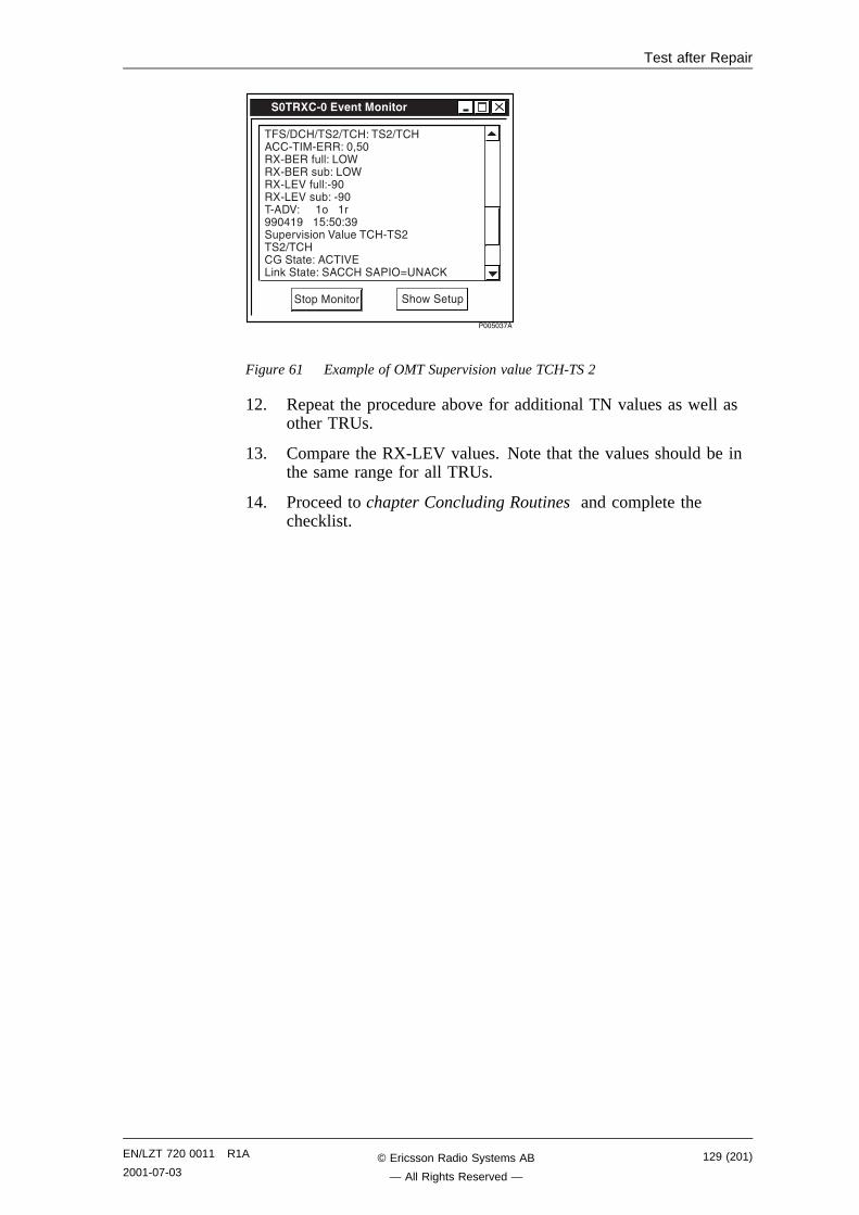
Test after Repair
���6�"!�
$3���!'3��0����#������
���=��5=��,=��5@���,=��5���/���/)��@��E6���/�)���#��@�.14��/�)���#(@�.14��/.)<��#��@/����/.)<��#(@�/���/��<@����������������������6@6�@"��#+��0�����<�#����5/��,��,=��5�A�����@�����<).�3�����@�����5�����1F 8��D
���+������� �&�2����#+
Figure 61 Example of OMT Supervision value TCH-TS 2
12. Repeat the procedure above for additional TN values as well asother TRUs.
13. Compare the RX-LEV values. Note that the values should be inthe same range for all TRUs.
14. Proceed to chapter Concluding Routines and complete thechecklist.
EN/LZT 720 0011 R1A
2001-07-03129 (201)© Ericsson Radio Systems AB
— All Rights Reserved —

Test after Repair
This page is intentionally left blank
130 (201) EN/LZT 720 0011 R1A
2001-07-03© Ericsson Radio Systems AB
— All Rights Reserved —
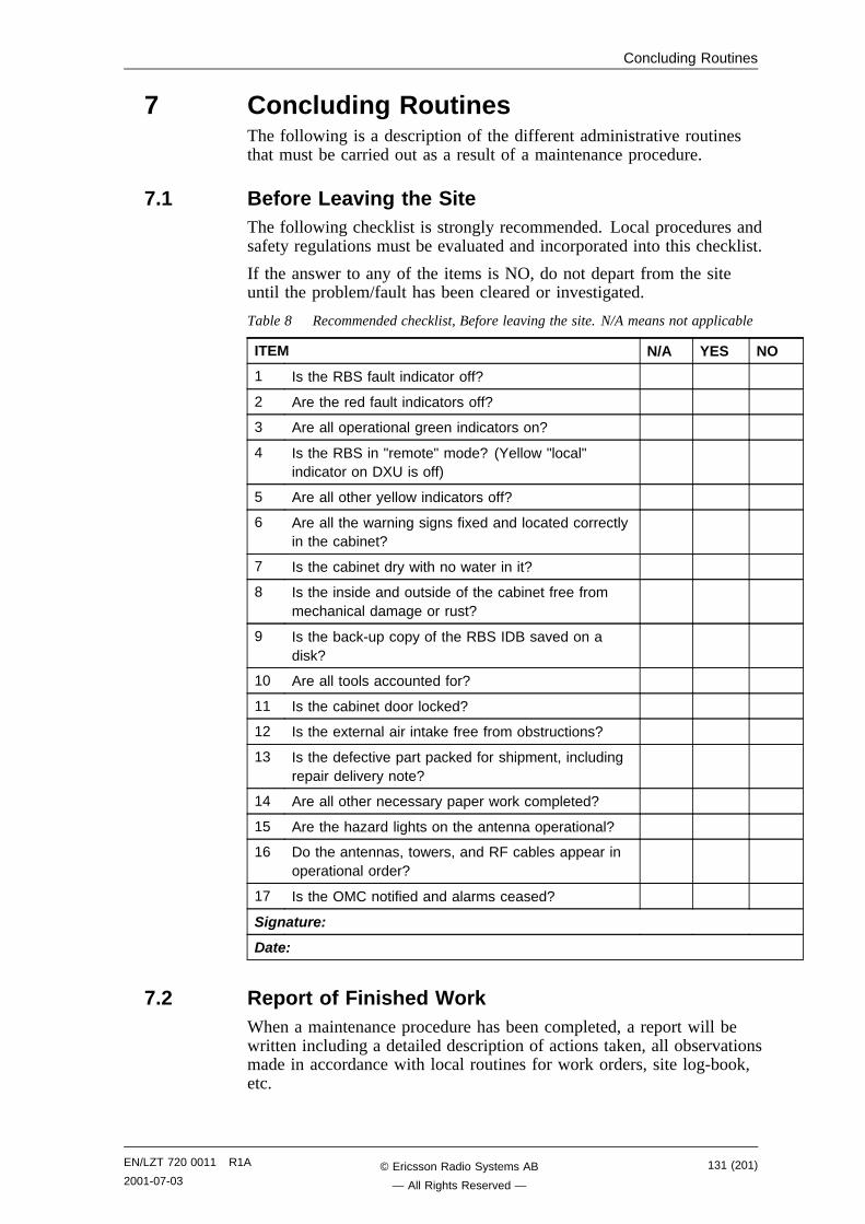
Concluding Routines
7 Concluding RoutinesThe following is a description of the different administrative routinesthat must be carried out as a result of a maintenance procedure.
7.1 Before Leaving the SiteThe following checklist is strongly recommended. Local procedures andsafety regulations must be evaluated and incorporated into this checklist.
If the answer to any of the items is NO, do not depart from the siteuntil the problem/fault has been cleared or investigated.
Table 8 Recommended checklist, Before leaving the site. N/A means not applicable
ITEM N/A YES NO
1 Is the RBS fault indicator off?
2 Are the red fault indicators off?
3 Are all operational green indicators on?
4 Is the RBS in "remote" mode? (Yellow "local"indicator on DXU is off)
5 Are all other yellow indicators off?
6 Are all the warning signs fixed and located correctlyin the cabinet?
7 Is the cabinet dry with no water in it?
8 Is the inside and outside of the cabinet free frommechanical damage or rust?
9 Is the back-up copy of the RBS IDB saved on adisk?
10 Are all tools accounted for?
11 Is the cabinet door locked?
12 Is the external air intake free from obstructions?
13 Is the defective part packed for shipment, includingrepair delivery note?
14 Are all other necessary paper work completed?
15 Are the hazard lights on the antenna operational?
16 Do the antennas, towers, and RF cables appear inoperational order?
17 Is the OMC notified and alarms ceased?
Signature:
Date:
7.2 Report of Finished WorkWhen a maintenance procedure has been completed, a report will bewritten including a detailed description of actions taken, all observationsmade in accordance with local routines for work orders, site log-book,etc.
EN/LZT 720 0011 R1A
2001-07-03131 (201)© Ericsson Radio Systems AB
— All Rights Reserved —
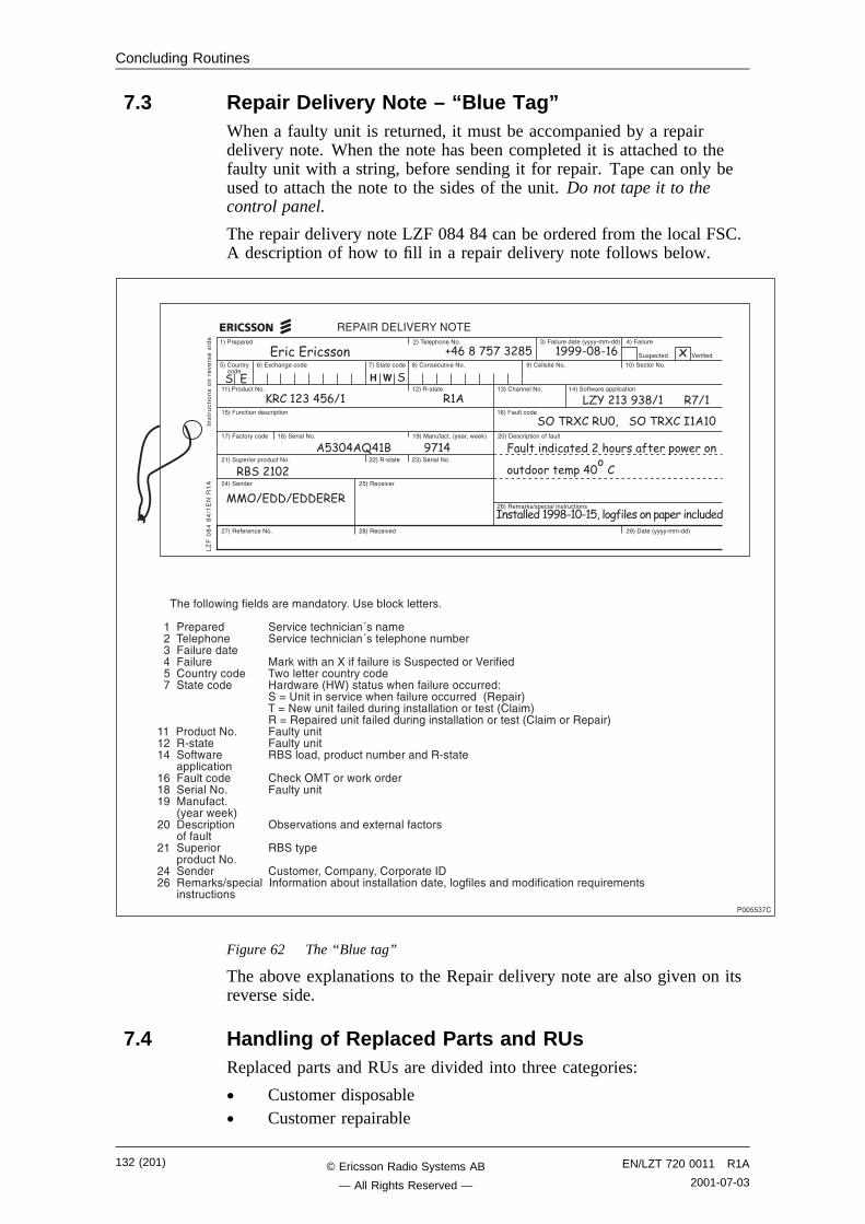
Concluding Routines
7.3 Repair Delivery Note – “Blue Tag”When a faulty unit is returned, it must be accompanied by a repairdelivery note. When the note has been completed it is attached to thefaulty unit with a string, before sending it for repair. Tape can only beused to attach the note to the sides of the unit. Do not tape it to thecontrol panel.
The repair delivery note LZF 084 84 can be ordered from the local FSC.A description of how to fill in a repair delivery note follows below.
�G����+��� ,G�����+&���8�C
6G���#��% ���
-G�)* &$�� ��� !G������ ��� �G����� #��0��8�C �G����������8�C ��G��� ����8�C
��G�����# ��8�C �,G��/���� �"G��&���8�C ��G�����2���++�� ���
�6G��# ������� ��+��� �-G��#��� ���
�!G�� ���%� ��� ��G�������8�C ��G��#� �C�H%��E�2��3G ,�G���� ��+��������#��
,�G��#+������+���# ��8�C ,,G��/���� ,"G�������8�C
,�G������ ,6G��� ��0��
,!G������� ��8�C ,�G��� ��0��
,-G�����3�=�+� �������# ����
"G����#�������H%%%%/��/��G �G����#��
�#�+� ��� <�������
,�G�����H%%%%/��/��G
�)������).�<)�:�81�)
����#
���������0
���������
.I���
����
�=�
)8��
��
���66"!�
������������� ���� � ����� ���������� �
���� 6��9���
������������ ��� �������������������� ��
������� � � !"#$%���&��"%'&���(�#���")%'��*�+'����
�#%&����%',*������ ������
-��%"$$'&�����������.�$�/)�$'�����*"*'�����$#&'&
�����&�������2�$����������������%C� ���(�� 3��������C
��������+���� �����0� ���� &� �J������,������+&�� �����0� ���� &� �J������+&���#�(����"�����#��������������#�� ����3�2��&����������#�������#�+� �������<���������6����#��%� ��� ���2��������� �#��%� �����!������� ��� ��5��2���H54G����#��2&�����#���� #����@
����F� ��������0� ��2&�����#���� #������H��+��G����F�8�2�#����������#��$������������������H����G����F���+�����#����������#��$������������������H����������+��G
��������# ��8�C ���#��%�#���,���/���� ���#��%�#����������2���� ���������E�+���# ��#�(������/����������++�� ����-���#��� ��� ���&� 3�1������2��3����������������8�C ���#��%�#�������#� �C������H%���2��3G,������ ��+��� ��1(���0��������*������ ��������������#��,����#+����� �������%+�������+���# ��8�C,�������� ���#������E����+%E����+�������,-������3�=�+� �������������(�#��������������E���$�������������� ������;#�����������������# ����
�0�1�2���3�.����0�1�2��-����
440��55��55����
Figure 62 The “Blue tag”
The above explanations to the Repair delivery note are also given on itsreverse side.
7.4 Handling of Replaced Parts and RUsReplaced parts and RUs are divided into three categories:
• Customer disposable• Customer repairable
132 (201) EN/LZT 720 0011 R1A
2001-07-03© Ericsson Radio Systems AB
— All Rights Reserved —
Concluding Routines
• Depot repairable
The definitions of these categories as well as explanations how to treatthe parts is given below.
Customer disposable
Customer disposable parts are consumable parts, which have no lowersub-assembly or component that can be used to repair them.
These items are identified in the appropriate RBS Spare PartsCatalogue as "Recommended spare parts for customer stock (notrepairable)" or "Other available parts".
Spare Parts Catalogue
Examples of these parts are:
• Cables and wiring• Connectors• Fuses, circuit breakers, varistors and overvoltage arresters• Fans, compressors and heaters• Printed circuit board assemblies (circuit cards, backplanes,
temperature sensors and humidity sensors)• Batteries• Antennas• Transformers• Capacitors• Mechanical hardware (doors, hinges, plates, locks, seals, gaskets,
brackets and other parts of the RBS cabinet)
Unless under contractual warranty, after replacement, these parts shallbe disposed of locally. Do not return these parts to Ericsson forreplacement, repair or disposal.
Customer repairable
Customer repairable parts are such parts, which have a lowersub-assembly or component that can be used to repair them.
These items are identified in the appropriate RBS Spare PartsCatalogue as "Recommended spare parts for customer stock (notrepairable)" or "Other available parts".
Spare Parts Catalogue
Examples of these parts are:
• IDMs
Unless under contractual warranty, after replacement, these parts shallbe repaired locally at the RBS site or in a local repair shop.
EN/LZT 720 0011 R1A
2001-07-03133 (201)© Ericsson Radio Systems AB
— All Rights Reserved —
Concluding Routines
Depot repairable
Depot repairable parts are for direct one to one replacement at the RBSsite.
These items are identified in the appropriate RBS Spare Parts Catalogueas "Recommended spare parts for customer stock (repairable)".
Spare Parts Catalogue
Examples of these parts are:
• CDUs• DXU• PSUs• TRUs• CXU
After replacement, these parts must be returned to Ericsson for repair.Maintenance personnel must attach a repair delivery note, LZF 084 64(Blue Tag), to the returned part. The repair delivery note shall include aclear description of the fault found. Refer to the section "RepairDelivery Note – ‘Blue Tag’" for instructions on completing a repairdelivery note.
7.5 Transport of a Repairable UnitThe repairable unit must be protected against ESD and damage due totransport. Therefore the repairable unit must be packed in an ESD-insulated plastic bag and transported in a shock-absorbing box. Thismust be done by re-using the same packing material as the spare unitwas delivered in. Refer to the appropriate Spare Parts Catalogue todetermine which repairable units should be returned for repair.
Spare Parts Catalogue
7.6 Trouble Report on Equipment or on this ManualA trouble report should be written when system components are notoperating as expected or when disturbances occur repeatedly. It shouldnot be written for occasional hardware failures. A trouble report shouldalso be written when a fault is found in this manual. Any comments onthis manual can be submitted in a similar way.
When writing a trouble report, always include as much information aspossible. Write the trouble report as soon as possible, preferably at theRBS site. The next pages contain an example of a filled-in troublereport and a blank trouble report.
The trouble report should be sent to the nearest FSC for resolution andregistration in the Ericsson trouble report system MHS (ModificationHandling System). The FSC should forward the trouble report via thenode MHO ERA BTS.
134 (201) EN/LZT 720 0011 R1A
2001-07-03© Ericsson Radio Systems AB
— All Rights Reserved —
Concluding Routines
7.6.1 Special Explanations
Product number The product number can be found on thelabel of the unit. For example KRC 13147/01
R-state Revision state, found on the label of theunit after the product number. Forexample R1A
Site status Can be “Installation Test” or “Operation”
EN/LZT 720 0011 R1A
2001-07-03135 (201)© Ericsson Radio Systems AB
— All Rights Reserved —
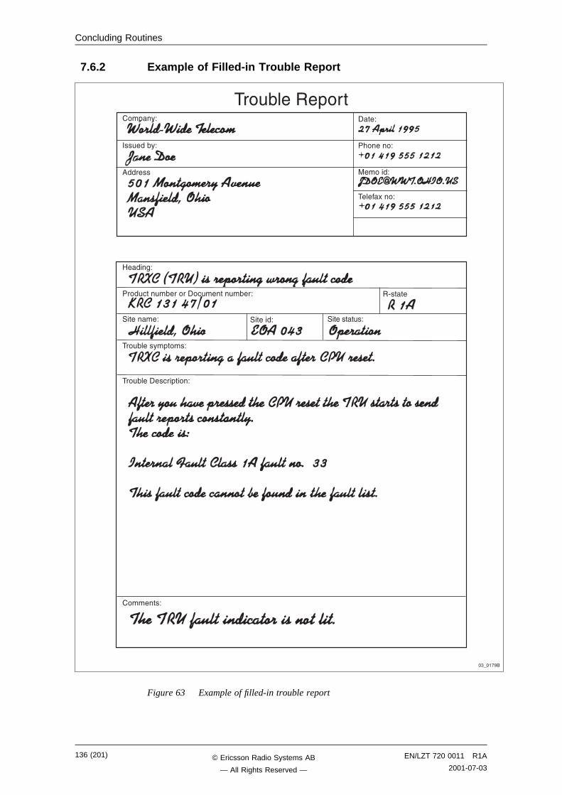
Concluding Routines
7.6.2 Example of Filled-in Trouble Report
5���$@
����# ��#�(�������� #����#�(��@ �/����
��������#�@�������@�������@
���#(����%�+����@
���#(������ ��+���@
���+%@
���#���(%@
�������
���@
�&����@
�������@
�����*��@
���#(�����+���
�������@
�"7��!��
Figure 63 Example of filled-in trouble report
136 (201) EN/LZT 720 0011 R1A
2001-07-03© Ericsson Radio Systems AB
— All Rights Reserved —
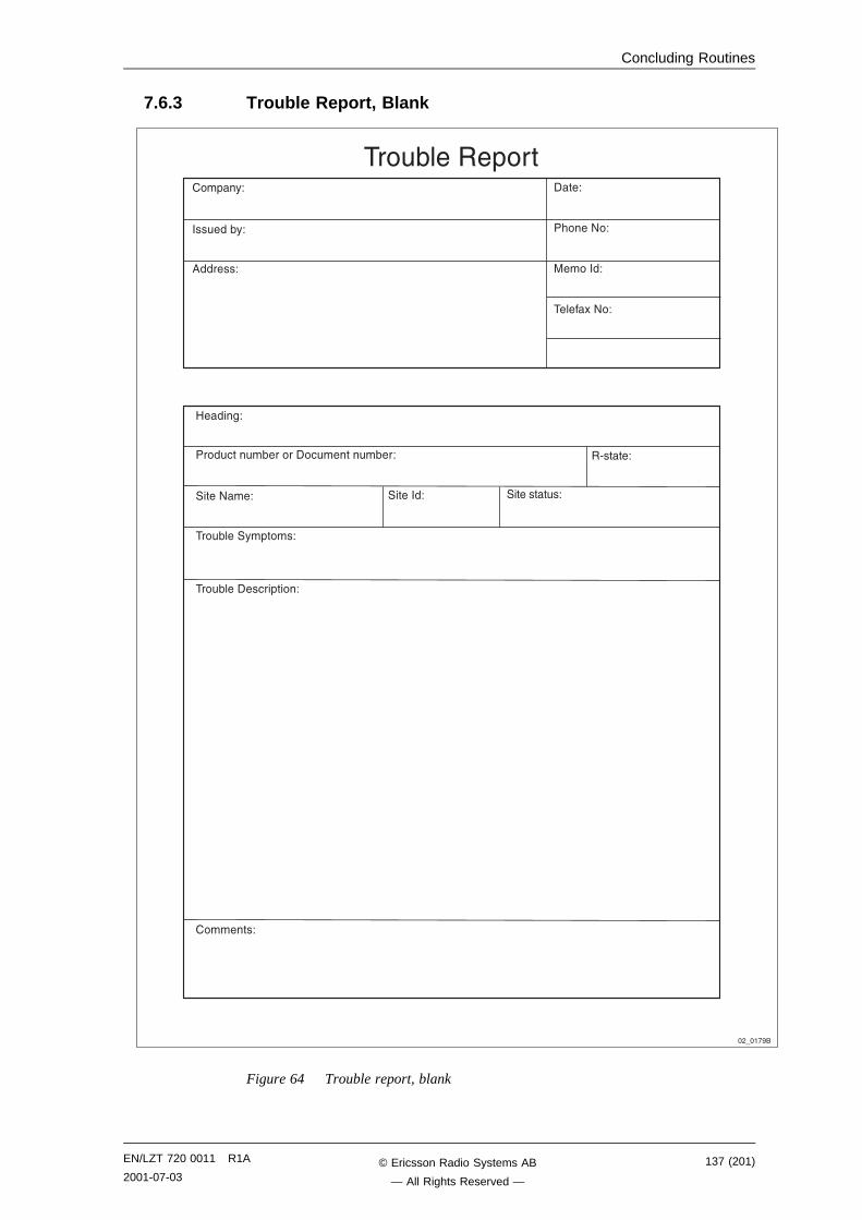
Concluding Routines
7.6.3 Trouble Report, Blank
�,7��!��
5���$@
����# ��#�(�������� #����#�(��@ �/����@
��������#�@�������@�����8��@
���#(����%�+����@
���#(������ ��+���@
���+%@
���#���(%@
�������@
���@
�&���8�@
�������@
�����*�8�@
���#(�����+���
�������@
Figure 64 Trouble report, blank
EN/LZT 720 0011 R1A
2001-07-03137 (201)© Ericsson Radio Systems AB
— All Rights Reserved —

Concluding Routines
This page is intentionally left blank
138 (201) EN/LZT 720 0011 R1A
2001-07-03© Ericsson Radio Systems AB
— All Rights Reserved —
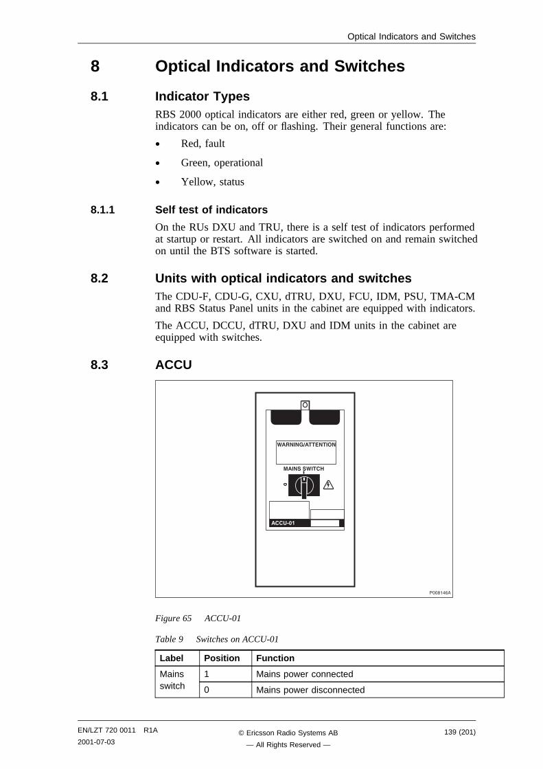
Optical Indicators and Switches
8 Optical Indicators and Switches
8.1 Indicator TypesRBS 2000 optical indicators are either red, green or yellow. Theindicators can be on, off or flashing. Their general functions are:
• Red, fault
• Green, operational
• Yellow, status
8.1.1 Self test of indicators
On the RUs DXU and TRU, there is a self test of indicators performedat startup or restart. All indicators are switched on and remain switchedon until the BTS software is started.
8.2 Units with optical indicators and switchesThe CDU-F, CDU-G, CXU, dTRU, DXU, FCU, IDM, PSU, TMA-CMand RBS Status Panel units in the cabinet are equipped with indicators.
The ACCU, DCCU, dTRU, DXU and IDM units in the cabinet areequipped with switches.
8.3 ACCU
������-�
9��.4.(�����.�4 .
#�4.$�$94�!6
�!!�'3�
Figure 65 ACCU-01
Table 9 Switches on ACCU-01
Label Position Function
1 Mains power connectedMainsswitch 0 Mains power disconnected
EN/LZT 720 0011 R1A
2001-07-03139 (201)© Ericsson Radio Systems AB
— All Rights Reserved —
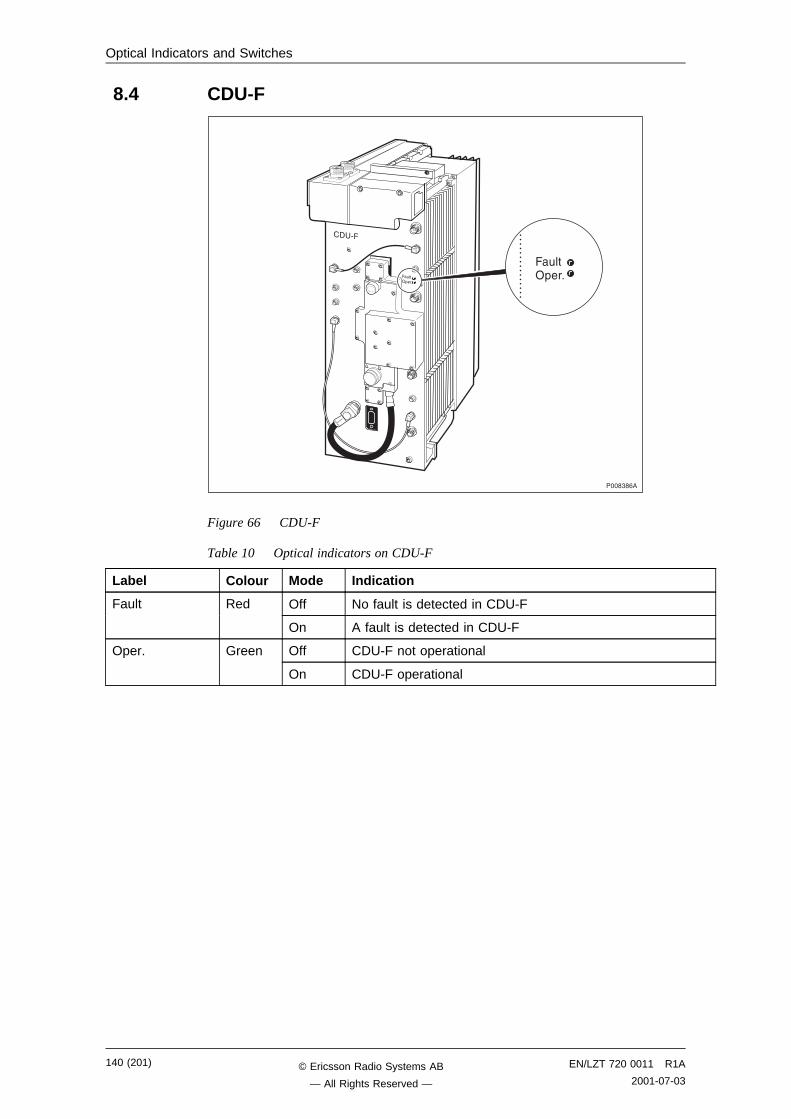
Optical Indicators and Switches
8.4 CDU-F
����"�-�
�� /�
�#��1+��C
�#��1+��C
Figure 66 CDU-F
Table 10 Optical indicators on CDU-F
Label Colour Mode Indication
Fault Red Off No fault is detected in CDU-F
On A fault is detected in CDU-F
Oper. Green Off CDU-F not operational
On CDU-F operational
140 (201) EN/LZT 720 0011 R1A
2001-07-03© Ericsson Radio Systems AB
— All Rights Reserved —
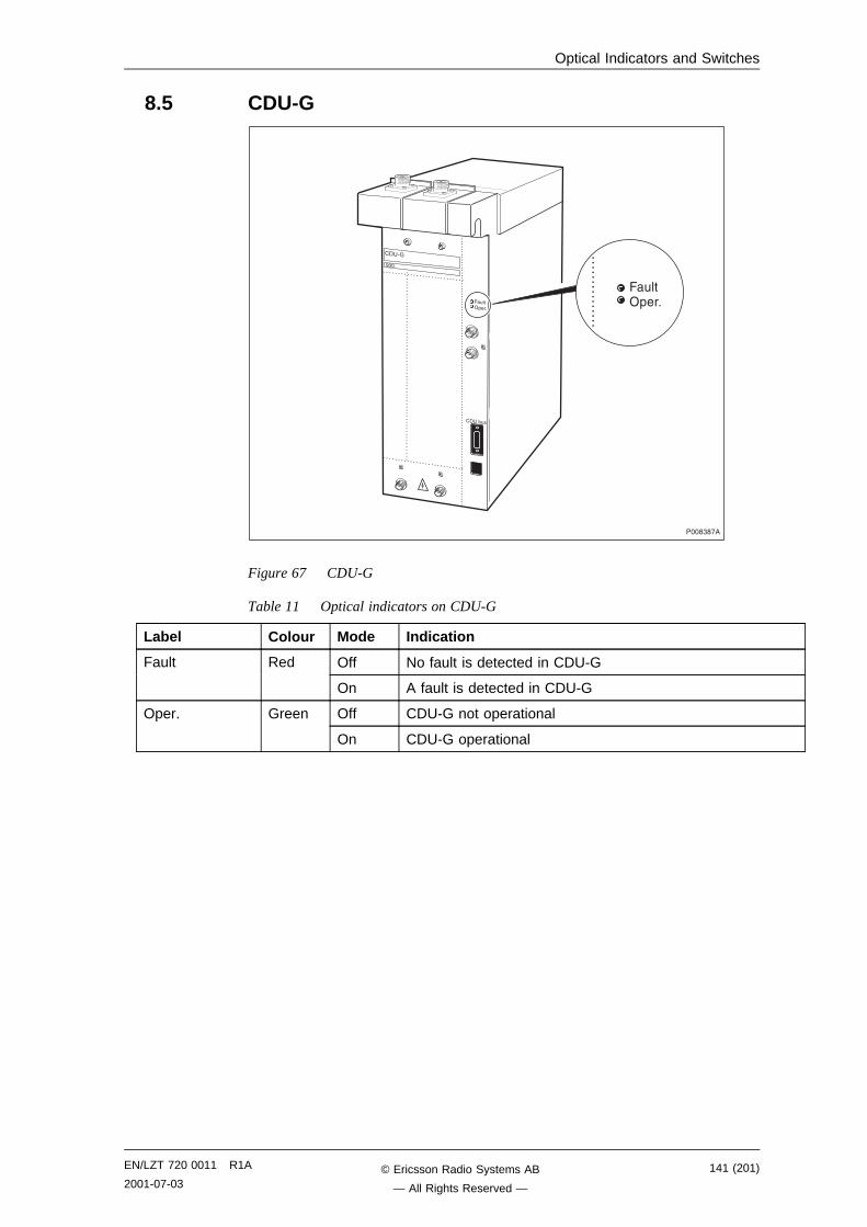
Optical Indicators and Switches
8.5 CDU-G
�� /A
���
�� �(#�
����"�!�
�#��1+��C
�#��1+��C
Figure 67 CDU-G
Table 11 Optical indicators on CDU-G
Label Colour Mode Indication
Fault Red Off No fault is detected in CDU-G
On A fault is detected in CDU-G
Oper. Green Off CDU-G not operational
On CDU-G operational
EN/LZT 720 0011 R1A
2001-07-03141 (201)© Ericsson Radio Systems AB
— All Rights Reserved —
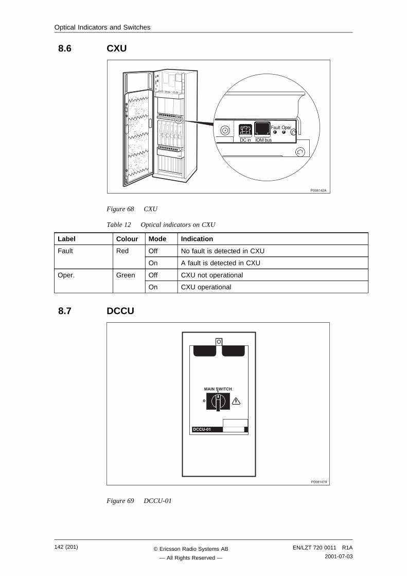
Optical Indicators and Switches
8.6 CXU
������,�
1+��C�#��
�1��(#�����
Figure 68 CXU
Table 12 Optical indicators on CXU
Label Colour Mode Indication
Fault Red Off No fault is detected in CXU
On A fault is detected in CXU
Oper. Green Off CXU not operational
On CXU operational
8.7 DCCU
#�4.�$94�!6
�!!�'3�
������!�
Figure 69 DCCU-01
142 (201) EN/LZT 720 0011 R1A
2001-07-03© Ericsson Radio Systems AB
— All Rights Reserved —
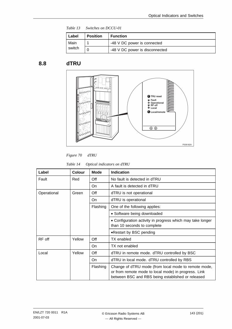
Optical Indicators and Switches
Table 13 Switches on DCCU-01
Label Position Function
1 -48 V DC power is connectedMainswitch 0 -48 V DC power is disconnected
8.8 dTRU
������,�
���������
��� �����������������
�����������
Figure 70 dTRU
Table 14 Optical indicators on dTRU
Label Colour Mode Indication
Fault Red Off No fault is detected in dTRU
On A fault is detected in dTRU
Operational Green Off dTRU is not operational
On dTRU is operational
Flashing One of the following applies:
• Software being downloaded
• Configuration activity in progress which may take longerthan 10 seconds to complete
•Restart by BSC pending
RF off Yellow Off TX enabled
On TX not enabled
Local Yellow Off dTRU in remote mode. dTRU controlled by BSC
On dTRU in local mode. dTRU controlled by RBS
Flashing Change of dTRU mode (from local mode to remote mode,or from remote mode to local mode) in progress. Linkbetween BSC and RBS being established or released
EN/LZT 720 0011 R1A
2001-07-03143 (201)© Ericsson Radio Systems AB
— All Rights Reserved —
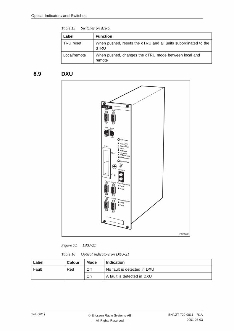
Optical Indicators and Switches
Table 15 Switches on dTRU
Label Function
TRU reset When pushed, resets the dTRU and all units subordinated to thedTRU
Local/remote When pushed, changes the dTRU mode between local andremote
8.9 DXU
���!�,!�
���������
��� ������������
� !�"�������� #�"�������
��$������%��&���
���������������
� !�"��
���'��
����� �����
����� �����
����� ����!
#� �$�
( $ � #
)*'��
)��'+
����������� , ����! �����
����������� ,
)����-
Figure 71 DXU-21
Table 16 Optical indicators on DXU-21
Label Colour Mode Indication
Fault Red Off No fault is detected in DXU
On A fault is detected in DXU
144 (201) EN/LZT 720 0011 R1A
2001-07-03© Ericsson Radio Systems AB
— All Rights Reserved —
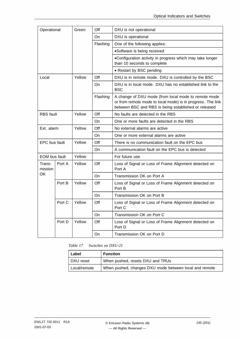
Optical Indicators and Switches
Operational Green Off DXU is not operational
On DXU is operational
Flashing One of the following applies:
•Software is being received
•Configuration activity in progress which may take longerthan 10 seconds to complete
• Restart by BSC pending
Local Yellow Off DXU is in remote mode. DXU is controlled by the BSC
On DXU is in local mode. DXU has no established link to theBSC
Flashing A change of DXU mode (from local mode to remote modeor from remote mode to local mode) is in progress. The linkbetween BSC and RBS is being established or released
RBS fault Yellow Off No faults are detected in the RBS
On One or more faults are detected in the RBS
Ext. alarm Yellow Off No external alarms are active
On One or more external alarms are active
EPC bus fault Yellow Off There is no communication fault on the EPC bus
On A communication fault on the EPC bus is detected
EOM bus fault Yellow For future use
Port A Yellow Off Loss of Signal or Loss of Frame Alignment detected onPort A
On Transmission OK on Port A
Port B Yellow Off Loss of Signal or Loss of Frame Alignment detected onPort B
On Transmission OK on Port B
Port C Yellow Off Loss of Signal or Loss of Frame Alignment detected onPort C
On Transmission OK on Port C
Port D Yellow Off Loss of Signal or Loss of Frame Alignment detected onPort D
Trans-missionOK
On Transmission OK on Port D
Table 17 Switches on DXU-21
Label Function
DXU reset When pushed, resets DXU and TRUs
Local/remote When pushed, changes DXU mode between local and remote
EN/LZT 720 0011 R1A
2001-07-03145 (201)© Ericsson Radio Systems AB
— All Rights Reserved —
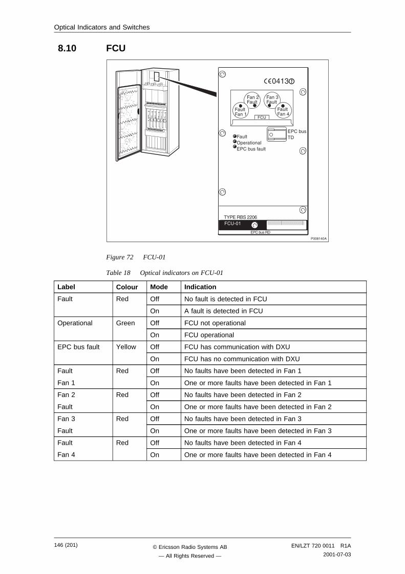
Optical Indicators and Switches
8.10 FCU
��������
�#�����
�#�����
��,�#��
��"�#��
��
�#��1+������)���(#���#��
�� /��
)���(#���
�:�)�����,,�-
)���(#����
���"
Figure 72 FCU-01
Table 18 Optical indicators on FCU-01
Label Colour Mode Indication
Fault Red Off No fault is detected in FCU
On A fault is detected in FCU
Operational Green Off FCU not operational
On FCU operational
EPC bus fault Yellow Off FCU has communication with DXU
On FCU has no communication with DXU
Fault Red Off No faults have been detected in Fan 1
Fan 1 On One or more faults have been detected in Fan 1
Fan 2 Red Off No faults have been detected in Fan 2
Fault On One or more faults have been detected in Fan 2
Fan 3 Red Off No faults have been detected in Fan 3
Fault On One or more faults have been detected in Fan 3
Fault Red Off No faults have been detected in Fan 4
Fan 4 On One or more faults have been detected in Fan 4
146 (201) EN/LZT 720 0011 R1A
2001-07-03© Ericsson Radio Systems AB
— All Rights Reserved —
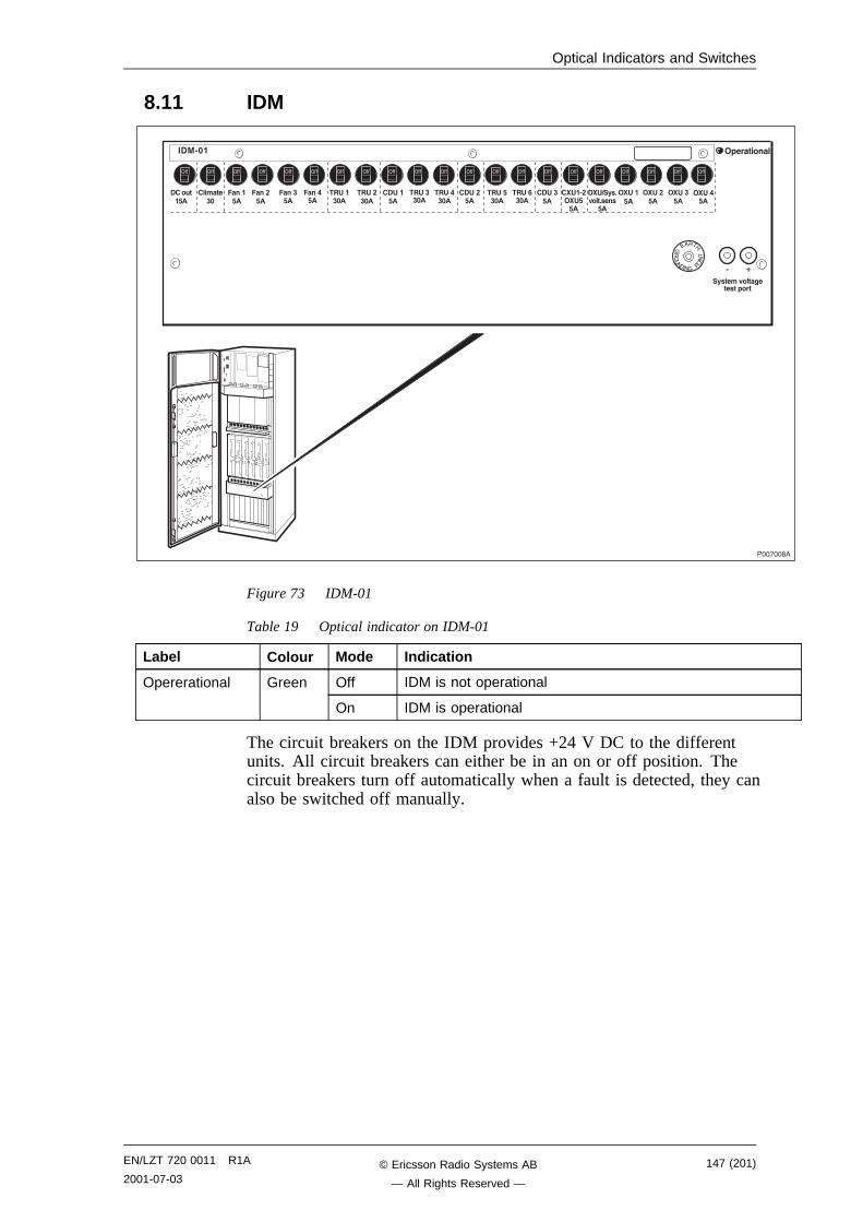
Optical Indicators and Switches
8.11 IDM
���!����
$/�����0���1����������
�!�����2�
!������3
���2�
���2�
���2�
������3�
������3�
!����2�
����2�3�
!����2�
!���'� ��22�
����2�
!����2�
��������4�#'3�
���2�
������3�
������3�
����+�3�
����$/�&0���&����2�
����2�
����2�
����2�
/ B
)���5
�1�8�
A�1 8��8A
Figure 73 IDM-01
Table 19 Optical indicator on IDM-01
Label Colour Mode Indication
Opererational Green Off IDM is not operational
On IDM is operational
The circuit breakers on the IDM provides +24 V DC to the differentunits. All circuit breakers can either be in an on or off position. Thecircuit breakers turn off automatically when a fault is detected, they canalso be switched off manually.
EN/LZT 720 0011 R1A
2001-07-03147 (201)© Ericsson Radio Systems AB
— All Rights Reserved —
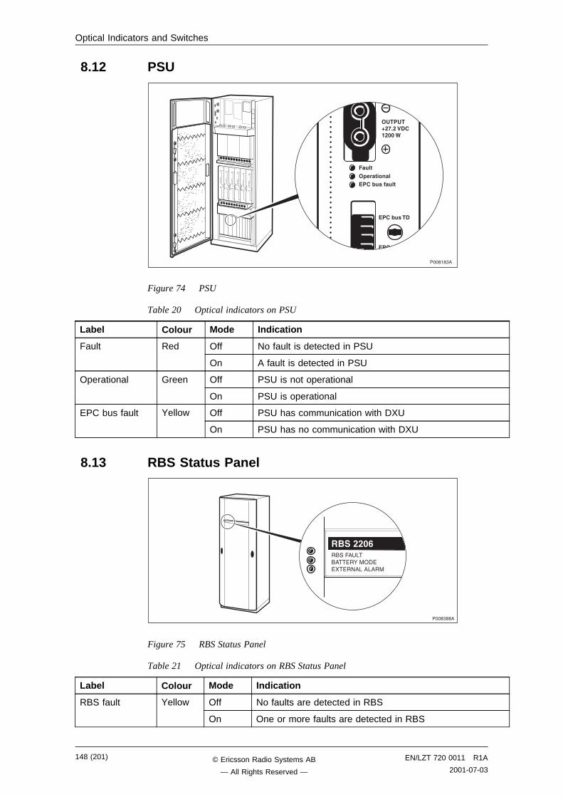
Optical Indicators and Switches
8.12 PSU
������"�
��� ��������� !�"�������
�� ��8�*&��5�!��33�9
� !�"�����
� !�"�����
Figure 74 PSU
Table 20 Optical indicators on PSU
Label Colour Mode Indication
Fault Red Off No fault is detected in PSU
On A fault is detected in PSU
Operational Green Off PSU is not operational
On PSU is operational
EPC bus fault Yellow Off PSU has communication with DXU
On PSU has no communication with DXU
8.13 RBS Status Panel
����"���
������ .�����)�:��1�))��)�8�.��.���
��$���3+
������ .�����)�:��1�))��)�8�.��.���
��$���3+
Figure 75 RBS Status Panel
Table 21 Optical indicators on RBS Status Panel
Label Colour Mode Indication
RBS fault Yellow Off No faults are detected in RBS
On One or more faults are detected in RBS
148 (201) EN/LZT 720 0011 R1A
2001-07-03© Ericsson Radio Systems AB
— All Rights Reserved —

Preventive Maintenance
External alarm Yellow Off No external alarms are active
On One or more external alarms are active
Battery mode Yellow Off No battery power used
On Battery power supply fully or partly used
8.14 TMA CM
�����
���/��
���������
�����
���������
����"���
Figure 76 TMA CM
Table 22 Optical Indicators on TMA CM
Label Colour Mode Indication
Fault Red Off No fault is detected in TMA CM
On A fault is detected in TMA CM
Operational Green Off TMA CM is not operational
On TMA CM is operational
1 Green Off TMA 1 is not operational
On TMA 1 is operational
2 Green Off TMA 2 is not operational
On TMA 2 is operational
3 Green Off TMA 3 is not operational
On TMA 3 is operational
4 Green Off TMA 4 is not operational
On TMA 4 is operational
5 Green Off TMA 5 is not operational
On TMA 5 is operational
6 Green Off TMA 6 is not operational
TMAoper.
On TMA 6 is operational
EN/LZT 720 0011 R1A
2001-07-03149 (201)© Ericsson Radio Systems AB
— All Rights Reserved —

Preventive Maintenance
This page is intentionally left blank
150 (201) EN/LZT 720 0011 R1A
2001-07-03© Ericsson Radio Systems AB
— All Rights Reserved —
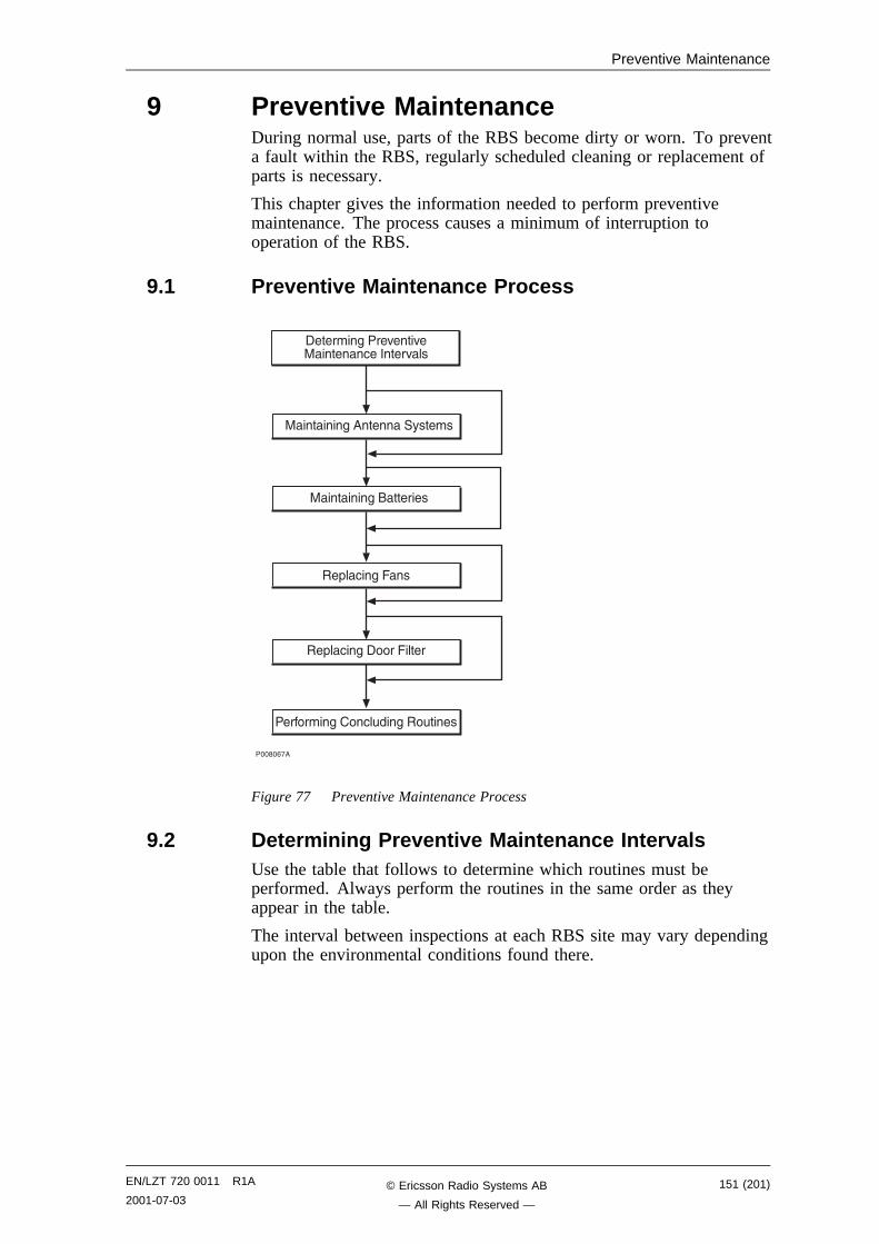
Preventive Maintenance
9 Preventive MaintenanceDuring normal use, parts of the RBS become dirty or worn. To preventa fault within the RBS, regularly scheduled cleaning or replacement ofparts is necessary.
This chapter gives the information needed to perform preventivemaintenance. The process causes a minimum of interruption tooperation of the RBS.
9.1 Preventive Maintenance Process
�����-!�
�������$����0���0����� ������0��
�����$���������
��������$��� �#��$���#����
��+� �$������������
��+� �$���
�����$������%�����
Figure 77 Preventive Maintenance Process
9.2 Determining Preventive Maintenance IntervalsUse the table that follows to determine which routines must beperformed. Always perform the routines in the same order as theyappear in the table.
The interval between inspections at each RBS site may vary dependingupon the environmental conditions found there.
EN/LZT 720 0011 R1A
2001-07-03151 (201)© Ericsson Radio Systems AB
— All Rights Reserved —
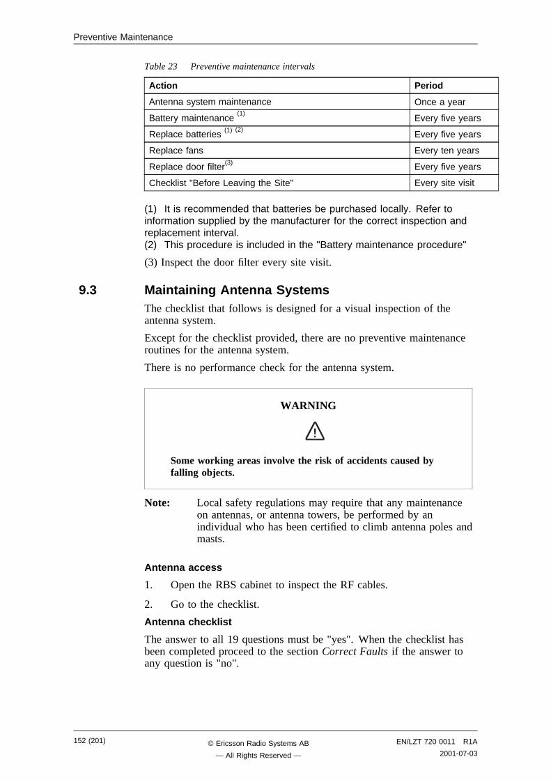
Preventive Maintenance
Table 23 Preventive maintenance intervals
Action Period
Antenna system maintenance Once a year
Battery maintenance(1)
Every five years
Replace batteries (1) (2)Every five years
Replace fans Every ten years
Replace door filter(3) Every five years
Checklist "Before Leaving the Site" Every site visit
(1) It is recommended that batteries be purchased locally. Refer toinformation supplied by the manufacturer for the correct inspection andreplacement interval.(2) This procedure is included in the "Battery maintenance procedure"
(3) Inspect the door filter every site visit.
9.3 Maintaining Antenna SystemsThe checklist that follows is designed for a visual inspection of theantenna system.
Except for the checklist provided, there are no preventive maintenanceroutines for the antenna system.
There is no performance check for the antenna system.
WARNING
Some working areas involve the risk of accidents caused byfalling objects.
Note: Local safety regulations may require that any maintenanceon antennas, or antenna towers, be performed by anindividual who has been certified to climb antenna poles andmasts.
Antenna access
1. Open the RBS cabinet to inspect the RF cables.
2. Go to the checklist.
Antenna checklist
The answer to all 19 questions must be "yes". When the checklist hasbeen completed proceed to the section Correct Faults if the answer toany question is "no".
152 (201) EN/LZT 720 0011 R1A
2001-07-03© Ericsson Radio Systems AB
— All Rights Reserved —
Preventive Maintenance
Table 24 Antenna checklist
ITEM N/A1 Yes No
1 Are poles in safe condition, that is, free of cracks, notbent or loose?
2 Is lightning protection secure and functional?
3 Is the TMA firmly mounted and in good condition?
4 Do all cables have markers?
5 Are cables secured to poles (approximately once every0.6 meters)?
6 Are the cable seals at the entry point into the cabinet ingood condition?
7 Are all cables free from abrasions, cuts and cracks?
8 Are all cable connector seals in good condition?
9 Are all cable ducts dry and the seals in good condition?
10 Are antenna towers and legs free of corrosion?
11 Are antenna towers free of bows or bends?
12 Are hazard lights operational ?
13 Are support pedestals free of signs of wear and/orcracks?
14 Are the guy wires relatively free of corrosion?
15 Are the guy wires free of signs of slipping?
16 Are the guy wires free of broken strands?
17 Are the antennas correctly orientated?
18 Are the antennas firmly mounted?
19 Is the RBS transmission path free of obstructions? (Nonew buildings, towers, and so on blocking it sinceinstallation.)
Signature:
Date:
1N/A stands for not applicable.
Correct faults
1. Only tighten loose connections, or replace RF cables in thecabinet.
2. Contact the supervisor to inform them of any other faults foundwhen performing the checklist as further repair activitis mayrequire field technicans trained and certified to climb towers.
9.4 Maintaining BatteriesThis section describes how to access the batteries, both internal andexternal when used. There is also a battery checklist and instructions onhow to correct faults at the end of the section.
EN/LZT 720 0011 R1A
2001-07-03153 (201)© Ericsson Radio Systems AB
— All Rights Reserved —
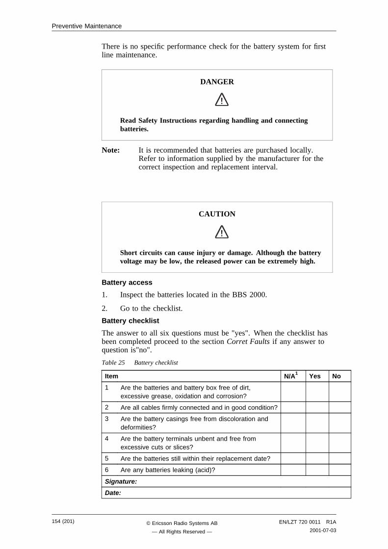
Preventive Maintenance
There is no specific performance check for the battery system for firstline maintenance.
DANGER
Read Safety Instructions regarding handling and connectingbatteries.
Note: It is recommended that batteries are purchased locally.Refer to information supplied by the manufacturer for thecorrect inspection and replacement interval.
CAUTION
Short circuits can cause injury or damage. Although the batteryvoltage may be low, the released power can be extremely high.
Battery access
1. Inspect the batteries located in the BBS 2000.
2. Go to the checklist.
Battery checklist
The answer to all six questions must be "yes". When the checklist hasbeen completed proceed to the section Corret Faults if any answer toquestion is"no".
Table 25 Battery checklist
Item N/A1 Yes No
1 Are the batteries and battery box free of dirt,excessive grease, oxidation and corrosion?
2 Are all cables firmly connected and in good condition?
3 Are the battery casings free from discoloration anddeformities?
4 Are the battery terminals unbent and free fromexcessive cuts or slices?
5 Are the batteries still within their replacement date?
6 Are any batteries leaking (acid)?
Signature:
Date:
154 (201) EN/LZT 720 0011 R1A
2001-07-03© Ericsson Radio Systems AB
— All Rights Reserved —
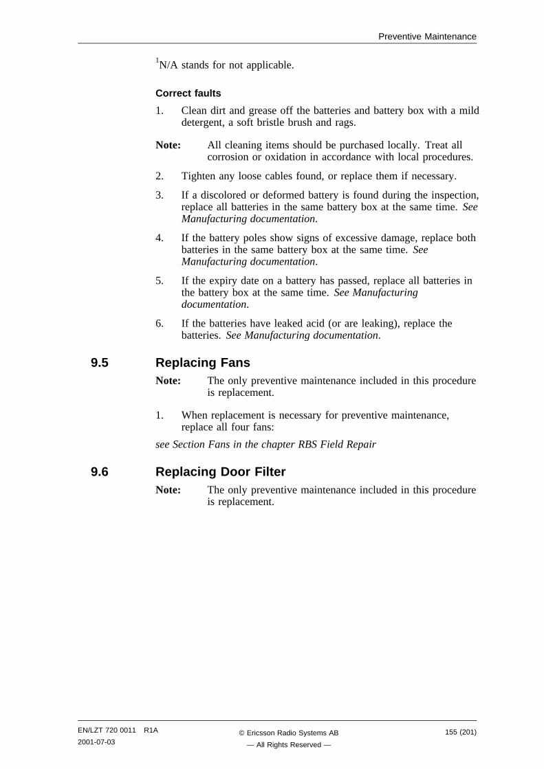
Preventive Maintenance
1N/A stands for not applicable.
Correct faults
1. Clean dirt and grease off the batteries and battery box with a milddetergent, a soft bristle brush and rags.
Note: All cleaning items should be purchased locally. Treat allcorrosion or oxidation in accordance with local procedures.
2. Tighten any loose cables found, or replace them if necessary.
3. If a discolored or deformed battery is found during the inspection,replace all batteries in the same battery box at the same time. SeeManufacturing documentation.
4. If the battery poles show signs of excessive damage, replace bothbatteries in the same battery box at the same time. SeeManufacturing documentation.
5. If the expiry date on a battery has passed, replace all batteries inthe battery box at the same time. See Manufacturingdocumentation.
6. If the batteries have leaked acid (or are leaking), replace thebatteries. See Manufacturing documentation.
9.5 Replacing FansNote: The only preventive maintenance included in this procedure
is replacement.
1. When replacement is necessary for preventive maintenance,replace all four fans:
see Section Fans in the chapter RBS Field Repair
9.6 Replacing Door FilterNote: The only preventive maintenance included in this procedure
is replacement.
EN/LZT 720 0011 R1A
2001-07-03155 (201)© Ericsson Radio Systems AB
— All Rights Reserved —
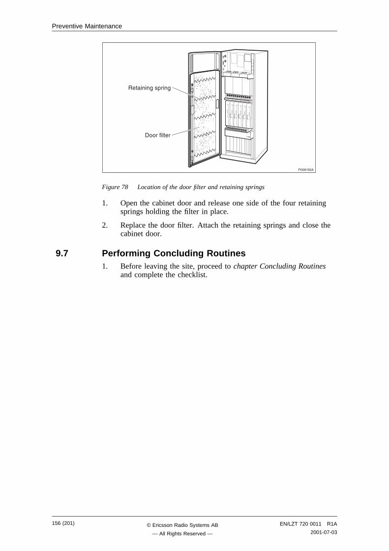
Preventive Maintenance
��������
�����$��+��$
�����������
Figure 78 Location of the door filter and retaining springs
1. Open the cabinet door and release one side of the four retainingsprings holding the filter in place.
2. Replace the door filter. Attach the retaining springs and close thecabinet door.
9.7 Performing Concluding Routines1. Before leaving the site, proceed to chapter Concluding Routines
and complete the checklist.
156 (201) EN/LZT 720 0011 R1A
2001-07-03© Ericsson Radio Systems AB
— All Rights Reserved —
Cable Connections
10 Cable ConnectionsThe cabinet cables are grouped into three cable groups:
• Power cables
• Opto cables
• Backplane cables
10.1 Power CablesThere are no power cables for the maintenance personnel to connect ifthe +24 V DC option is selected. 24 V power cables are factoryconnected.
230 V AC and -48 V DC power cables are pre-mounted to the cabinet.Connection of the power cables to the PSUs is shown in figure below.
����,!��
� , " �
�� �� �� �, �� �" �� ��
��
��� �������� 1�
�#�����
6 - ! �
Figure 79 230 V AC and -48 V DC power cables
Table 26 PSU power
Connector No. Product No. Connects to
1 to 4 — ACCU/DCCU connectionfield
5 to 8 — IDM panel
230 V AC power cable RPM 513 1341/02250 may substitute for the230 V AC power cable RPM 513 1178/02250 in some cabinet variants.
10.2 Opto CablesCables from the Cable set Basic are connected as shown in figure below.
EN/LZT 720 0011 R1A
2001-07-03157 (201)© Ericsson Radio Systems AB
— All Rights Reserved —
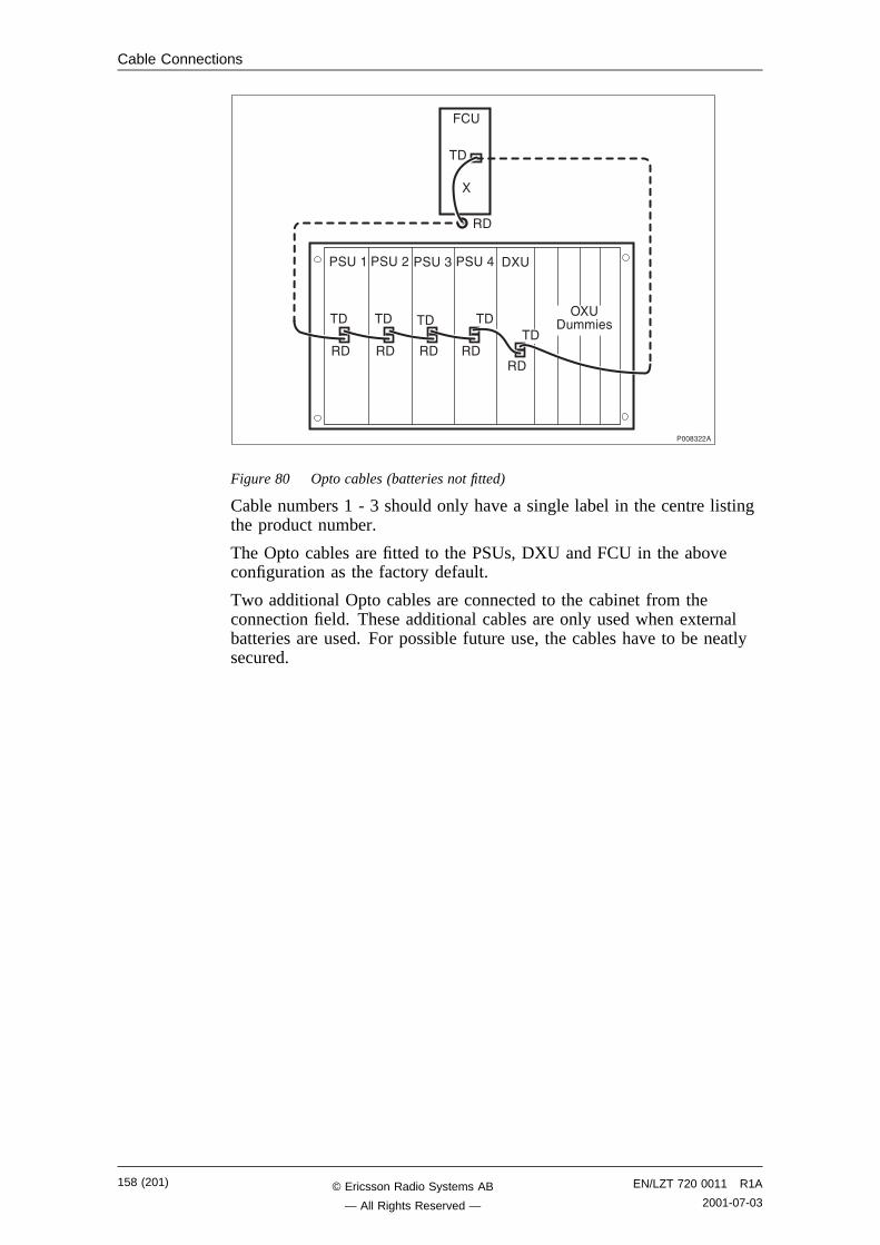
Cable Connections
��������
����",,�
��
������
�� �� �� �, �� �" �� �� ��
1� �#�����
�� ��
��
��
��
�
Figure 80 Opto cables (batteries not fitted)
Cable numbers 1 - 3 should only have a single label in the centre listingthe product number.
The Opto cables are fitted to the PSUs, DXU and FCU in the aboveconfiguration as the factory default.
Two additional Opto cables are connected to the cabinet from theconnection field. These additional cables are only used when externalbatteries are used. For possible future use, the cables have to be neatlysecured.
158 (201) EN/LZT 720 0011 R1A
2001-07-03© Ericsson Radio Systems AB
— All Rights Reserved —
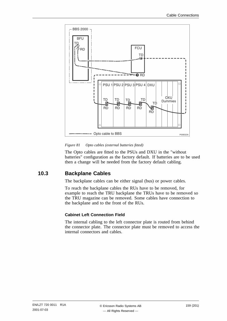
Cable Connections
��
����","�
��������
����
�� �� �� �, �� �" �� �� ��
1� �#�����
�� ��
��
��
��
�����,���
��
��
��
��
1+��� (���������
Figure 81 Opto cables (external batteries fitted)
The Opto cables are fitted to the PSUs and DXU in the "withoutbatteries" configuration as the factory default. If batteries are to be usedthen a change will be needed from the factory default cabling.
10.3 Backplane CablesThe backplane cables can be either signal (bus) or power cables.
To reach the backplane cables the RUs have to be removed, forexample to reach the TRU backplane the TRUs have to be removed sothe TRU magazine can be removed. Some cables have connection tothe backplane and to the front of the RUs.
Cabinet Left Connection Field
The internal cabling to the left connector plate is routed from behindthe connector plate. The connector plate must be removed to access theinternal connectors and cables.
EN/LZT 720 0011 R1A
2001-07-03159 (201)© Ericsson Radio Systems AB
— All Rights Reserved —
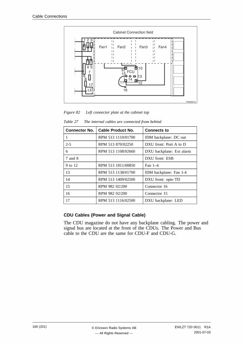
Cable Connections
����"�!�
�(������� ���������
�� �, �" ��
��
.)�
� , "
� 6
-!
�
�!
� ��
�,��
�"
��
�-
�6
Figure 82 Left connector plate at the cabinet top
Table 27 The internal cables are connected from behind
Connector No. Cable Product No. Connects to
1 RPM 513 1110/01700 IDM backplane: DC out
2-5 RPM 513 870/02250 DXU front: Port A to D
6 RPM 513 1108/02660 DXU backplane: Ext alarm
7 and 8 DXU front: ESB
9 to 12 RPM 513 1811/00850 Fan 1–4
13 RPM 513 1138/01700 IDM backplane: Fan 1-4
14 RPM 513 1409/02500 DXU front: opto TD
15 RPM 982 02/200 Connector 16
16 RPM 982 02/200 Connector 15
17 RPM 513 1116/02500 DXU backplane: LED
CDU Cables (Power and Signal Cable)
The CDU magazine do not have any backplane cabling. The power andsignal bus are located at the front of the CDUs. The Power and Buscable to the CDU are the same for CDU-F and CDU-G.
160 (201) EN/LZT 720 0011 R1A
2001-07-03© Ericsson Radio Systems AB
— All Rights Reserved —
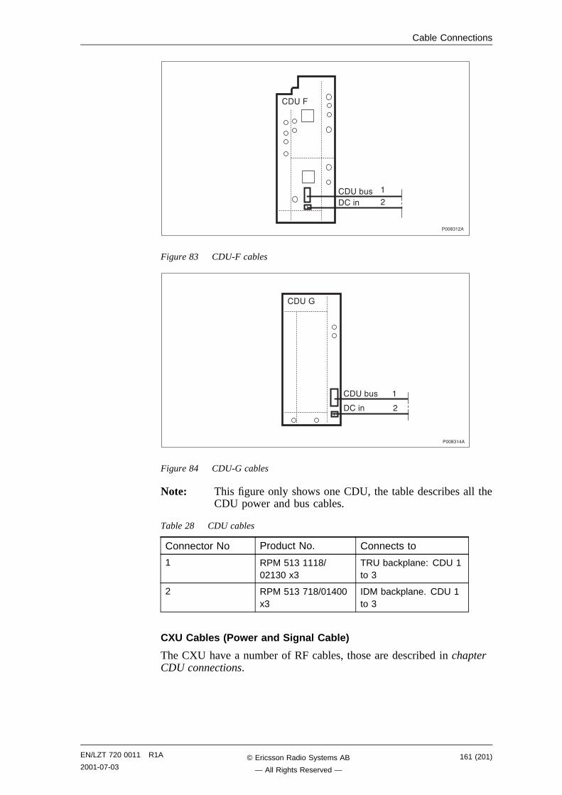
Cable Connections
����"�,�
,
�� ��
�� �(#�����
�
Figure 83 CDU-F cables
����"���
�� �A
�� �(#��������
����������������,
Figure 84 CDU-G cables
Note: This figure only shows one CDU, the table describes all theCDU power and bus cables.
Table 28 CDU cables
Connector No Product No. Connects to
1 RPM 513 1118/02130 x3
TRU backplane: CDU 1to 3
2 RPM 513 718/01400x3
IDM backplane. CDU 1to 3
CXU Cables (Power and Signal Cable)
The CXU have a number of RF cables, those are described in chapterCDU connections.
EN/LZT 720 0011 R1A
2001-07-03161 (201)© Ericsson Radio Systems AB
— All Rights Reserved —
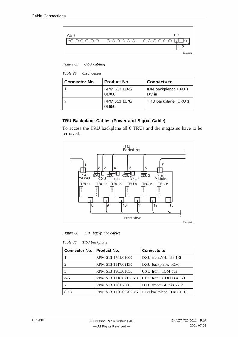
Cable Connections
����"�"�
�� ��
� ,
Figure 85 CXU cabling
Table 29 CXU cables
Connector No. Product No. Connects to
1 RPM 513 1162/01000
IDM backplane: CXU 1DC in
2 RPM 513 1178/01650
TRU backplane: CXU 1
TRU Backplane Cables (Power and Signal Cable)
To access the TRU backplane all 6 TRUs and the magazine have to beremoved.
����"���
�����0��2
�� � 3+��
�, " � 6 -
!
� � �� �� �, �"
�� �� �� �, �� �" �� �� �� �6 �� �-
�/-:/.�3� �� � �� , 1� 6
�1� �� �� �� �, �� �" !/�,:/.�3�
Figure 86 TRU backplane cables
Table 30 TRU backplane
Connector No. Product No. Connects to
1 RPM 513 1781/02000 DXU front:Y-Links 1-6
2 RPM 513 1117/02130 DXU backplane: IOM
3 RPM 513 1903/01650 CXU front: IOM bus
4-6 RPM 513 1118/02130 x3 CDU front: CDU Bus 1-3
7 RPM 513 1781/2000 DXU front:Y-Links 7-12
8-13 RPM 513 1120/00700 x6 IDM backplane: TRU 1- 6
162 (201) EN/LZT 720 0011 R1A
2001-07-03© Ericsson Radio Systems AB
— All Rights Reserved —
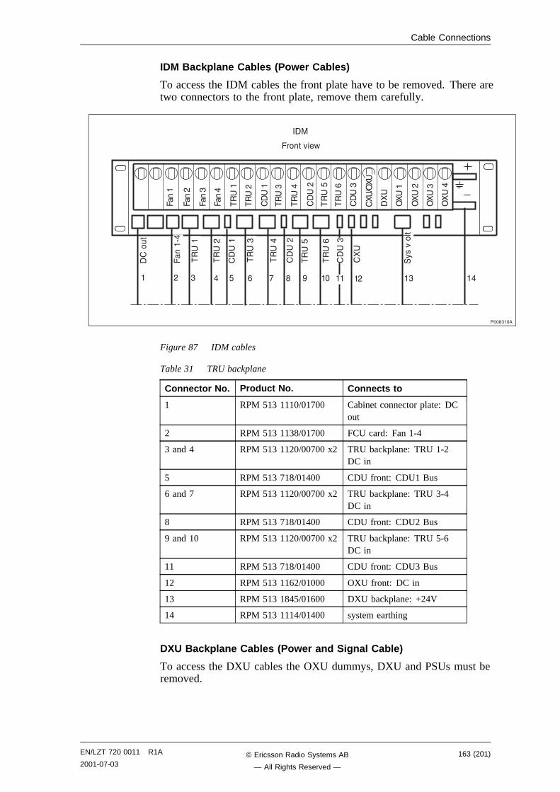
Cable Connections
IDM Backplane Cables (Power Cables)
To access the IDM cables the front plate have to be removed. There aretwo connectors to the front plate, remove them carefully.
����#�
���/�
�� ��
�� �,
�� �"
�� ��
�� ��
�� �,
�� �6
�� �-
��
���
�����0��2
����"���
1� ��
� , " � 6 - ! � � �� �� �, �" ��
1� �"
1� �,
1�
��
��
�� �"
�� �-
�� �6
�� ��
�� �"
�� �,
�� ��
���
��"
��,
���
�� ��
�� �,
�� �"
�%�
�0����
��
=1�
Figure 87 IDM cables
Table 31 TRU backplane
Connector No. Product No. Connects to
1 RPM 513 1110/01700 Cabinet connector plate: DCout
2 RPM 513 1138/01700 FCU card: Fan 1-4
3 and 4 RPM 513 1120/00700 x2 TRU backplane: TRU 1-2DC in
5 RPM 513 718/01400 CDU front: CDU1 Bus
6 and 7 RPM 513 1120/00700 x2 TRU backplane: TRU 3-4DC in
8 RPM 513 718/01400 CDU front: CDU2 Bus
9 and 10 RPM 513 1120/00700 x2 TRU backplane: TRU 5-6DC in
11 RPM 513 718/01400 CDU front: CDU3 Bus
12 RPM 513 1162/01000 OXU front: DC in
13 RPM 513 1845/01600 DXU backplane: +24V
14 RPM 513 1114/01400 system earthing
DXU Backplane Cables (Power and Signal Cable)
To access the DXU cables the OXU dummys, DXU and PSUs must beremoved.
EN/LZT 720 0011 R1A
2001-07-03163 (201)© Ericsson Radio Systems AB
— All Rights Reserved —
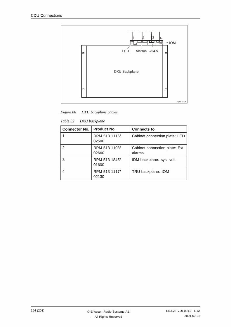
CDU Connections
����"���
�� �� 3+��
� , " �
.)� ����� B,��<
�1�
Figure 88 DXU backplane cables
Table 32 DXU backplane
Connector No. Product No. Connects to
1 RPM 513 1116/02500
Cabinet connection plate: LED
2 RPM 513 1108/02660
Cabinet connection plate: Extalarms
3 RPM 513 1845/01600
IDM backplane: sys. volt
4 RPM 513 1117/02130
TRU backplane: IOM
164 (201) EN/LZT 720 0011 R1A
2001-07-03© Ericsson Radio Systems AB
— All Rights Reserved —
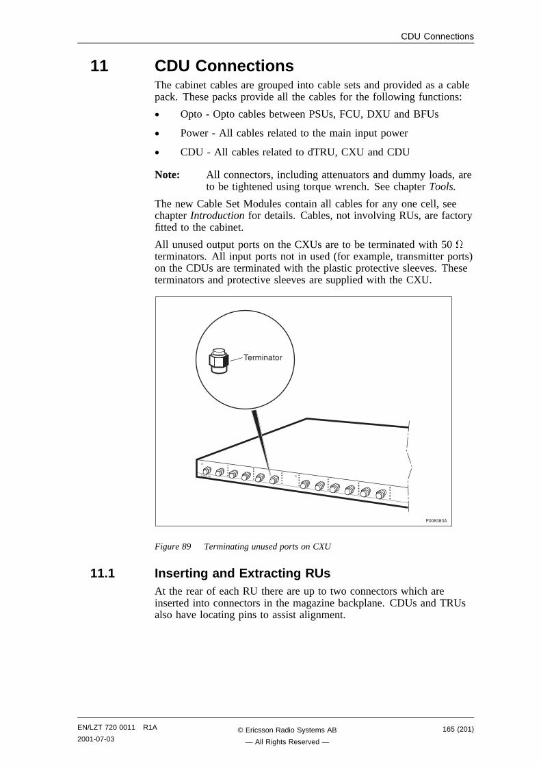
CDU Connections
11 CDU ConnectionsThe cabinet cables are grouped into cable sets and provided as a cablepack. These packs provide all the cables for the following functions:
• Opto - Opto cables between PSUs, FCU, DXU and BFUs
• Power - All cables related to the main input power
• CDU - All cables related to dTRU, CXU and CDU
Note: All connectors, including attenuators and dummy loads, areto be tightened using torque wrench. See chapter Tools.
The new Cable Set Modules contain all cables for any one cell, seechapter Introduction for details. Cables, not involving RUs, are factoryfitted to the cabinet.
All unused output ports on the CXUs are to be terminated with 50 terminators. All input ports not in used (for example, transmitter ports)on the CDUs are terminated with the plastic protective sleeves. Theseterminators and protective sleeves are supplied with the CXU.
������
��������
����"�"�
Figure 89 Terminating unused ports on CXU
11.1 Inserting and Extracting RUsAt the rear of each RU there are up to two connectors which areinserted into connectors in the magazine backplane. CDUs and TRUsalso have locating pins to assist alignment.
EN/LZT 720 0011 R1A
2001-07-03165 (201)© Ericsson Radio Systems AB
— All Rights Reserved —
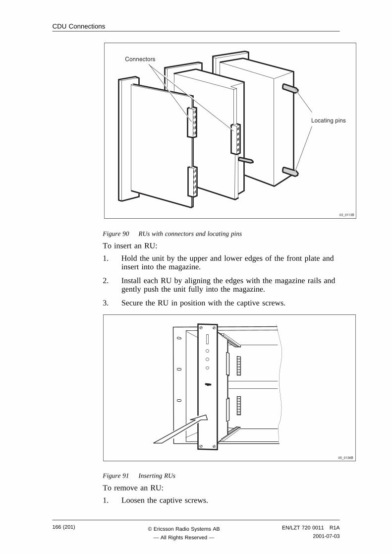
CDU Connections
�"7���"�
��� ����
.� ��$�+��
Figure 90 RUs with connectors and locating pins
To insert an RU:
1. Hold the unit by the upper and lower edges of the front plate andinsert into the magazine.
2. Install each RU by aligning the edges with the magazine rails andgently push the unit fully into the magazine.
3. Secure the RU in position with the captive screws.
�67��"-�
Figure 91 Inserting RUs
To remove an RU:
1. Loosen the captive screws.
166 (201) EN/LZT 720 0011 R1A
2001-07-03© Ericsson Radio Systems AB
— All Rights Reserved —
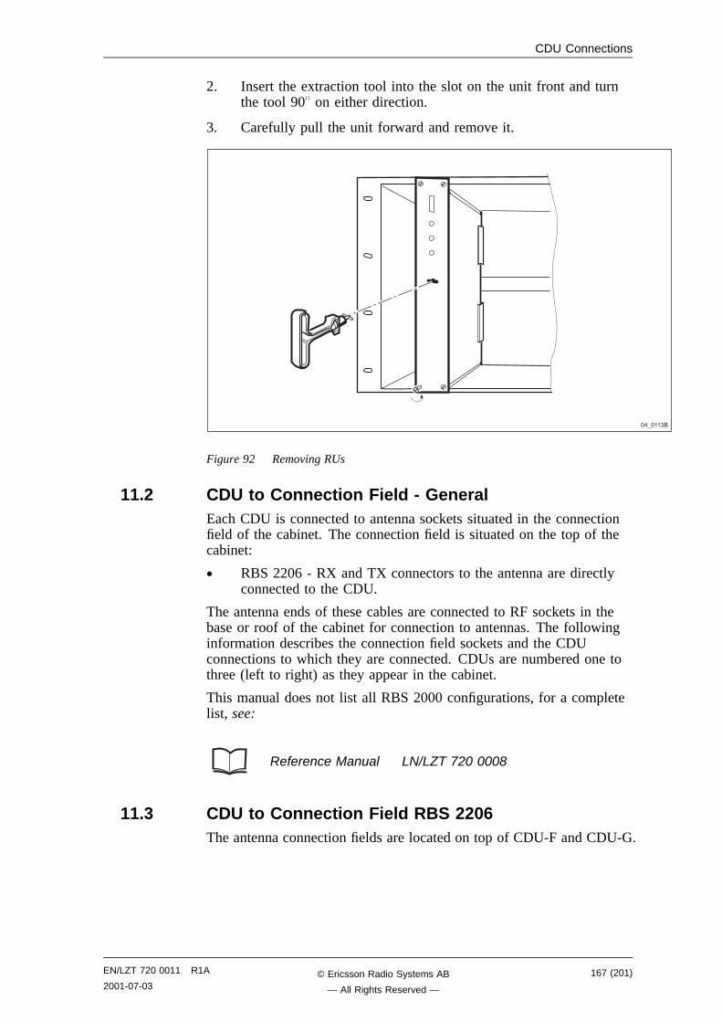
CDU Connections
2. Insert the extraction tool into the slot on the unit front and turnthe tool 90 on either direction.
3. Carefully pull the unit forward and remove it.
��7���"�
Figure 92 Removing RUs
11.2 CDU to Connection Field - GeneralEach CDU is connected to antenna sockets situated in the connectionfield of the cabinet. The connection field is situated on the top of thecabinet:
• RBS 2206 - RX and TX connectors to the antenna are directlyconnected to the CDU.
The antenna ends of these cables are connected to RF sockets in thebase or roof of the cabinet for connection to antennas. The followinginformation describes the connection field sockets and the CDUconnections to which they are connected. CDUs are numbered one tothree (left to right) as they appear in the cabinet.
This manual does not list all RBS 2000 configurations, for a completelist, see:
Reference Manual LN/LZT 720 0008
11.3 CDU to Connection Field RBS 2206The antenna connection fields are located on top of CDU-F and CDU-G.
EN/LZT 720 0011 R1A
2001-07-03167 (201)© Ericsson Radio Systems AB
— All Rights Reserved —
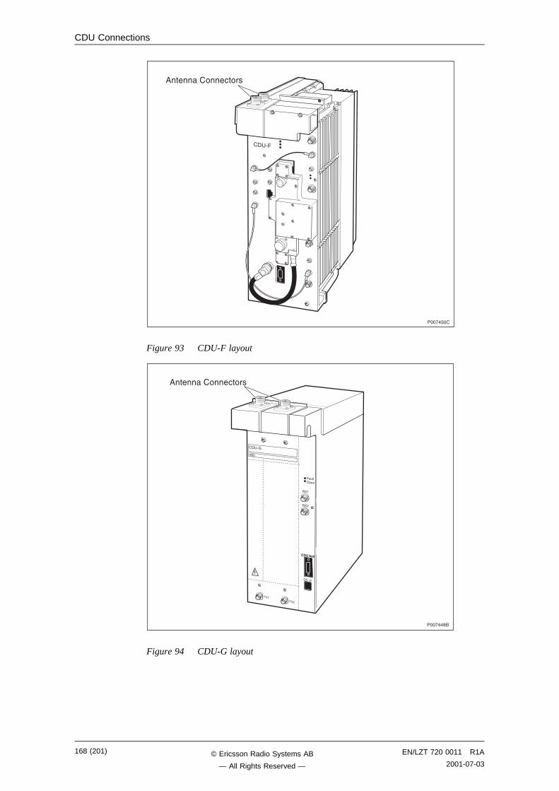
CDU Connections
���!�6��
�� /�
������� ����
Figure 93 CDU-F layout
�� /A
���
�� �(#��� �(#�
����
�����,
���!����
���
��,
�#��1+�
������� ����
Figure 94 CDU-G layout
168 (201) EN/LZT 720 0011 R1A
2001-07-03© Ericsson Radio Systems AB
— All Rights Reserved —
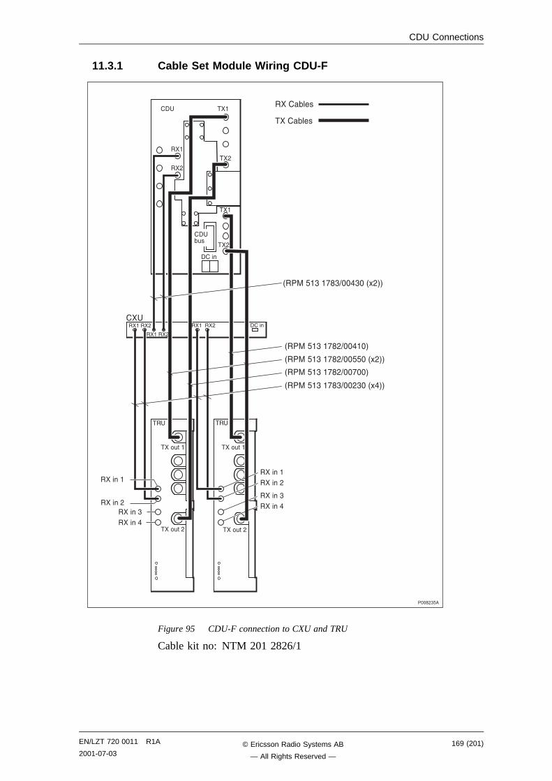
CDU Connections
11.3.1 Cable Set Module Wiring CDU-F
����,"6�
H����6�"��!�"=���"��H*,GG
H����6�"��!�,=�����G
H����6�"��!�,=��66��H*,GG
H����6�"��!�,=��!��G
H����6�"��!�"=��,"��H*�GG
����(���
����(���
��
����#���
����#��,
��
����#���
����#��,
������
�����,�����"������
�����������,
�����"������
�� ���
��,
���
��,
����
��
���
��,
�� (#�
����
������,
�������,������,
Figure 95 CDU-F connection to CXU and TRU
Cable kit no: NTM 201 2826/1
EN/LZT 720 0011 R1A
2001-07-03169 (201)© Ericsson Radio Systems AB
— All Rights Reserved —
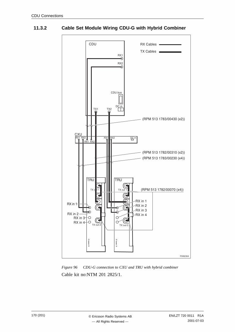
CDU Connections
11.3.2 Cable Set Module Wiring CDU-G with Hybrid Combiner
����(���
����(���
����,"-�
��
����#���
����#��,
������
�����,�����"������
�����������,�����"������
��
����
�� �������,
H����6�"��!�"=���"��H*,GG
H����6�"��!�,=��"���H*,GG
H����6�"��!�"=��,"��H*�GG
���
��,
�� �(#�
������������,
H����6�"��!�,=���!��H*�GG
��� ��,
��
����#��,
����#���
�������,
Figure 96 CDU-G connection to CXU and TRU with hybrid combiner
Cable kit no:NTM 201 2825/1.
170 (201) EN/LZT 720 0011 R1A
2001-07-03© Ericsson Radio Systems AB
— All Rights Reserved —
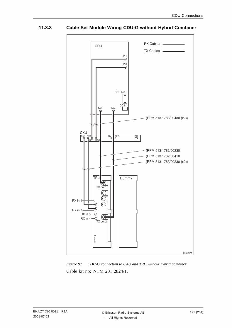
CDU Connections
11.3.3 Cable Set Module Wiring CDU-G without Hybrid Combiner
��
����
�� �������,
H����6�"��!�"=���"��H*,GG
H����6�"��!�,=��,"�
H����6�"��!�,=�����
����(���
����(������
��,
�� �(#�
��
����,"!�
��������,
��� ��,
��
����#��,
����#���
H����6�"��!�"=��,"��H*,GG
������
�����,�����"������
�#��%
��������,
Figure 97 CDU-G connection to CXU and TRU without hybrid combiner
Cable kit no: NTM 201 2824/1.
EN/LZT 720 0011 R1A
2001-07-03171 (201)© Ericsson Radio Systems AB
— All Rights Reserved —
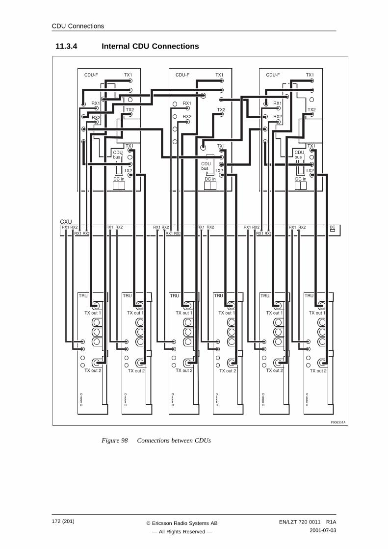
CDU Connections
11.3.4 Internal CDU Connections
����"6��
��
����#���
����#��,
��
����#���
����#��,
�� /� ���
��,
���
��,
����
��
���
��,
������,
�������,������,
��
����#���
����#��,
��
����#���
����#��,
�� /� ���
��,
���
��,
����
���
��,
�� (#�
������,
�������,������,
��
����#���
����#��,
��
����#���
����#��,
�� /� ���
��,
���
��,
����
���
��,
�� (#�
��
������,
�������,������,
�� (#�
Figure 98 Connections between CDUs
172 (201) EN/LZT 720 0011 R1A
2001-07-03© Ericsson Radio Systems AB
— All Rights Reserved —
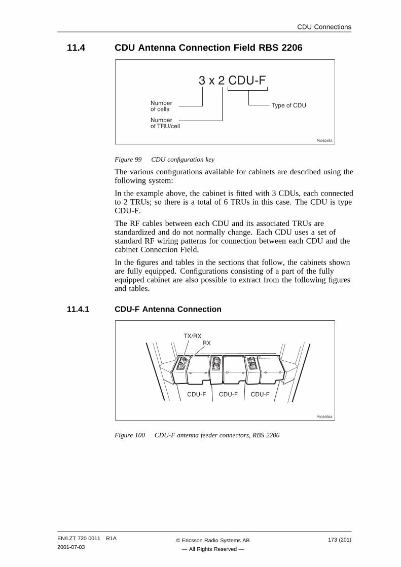
CDU Connections
11.4 CDU Antenna Connection Field RBS 2206
����,�6�
"�*�,��� /�
8#�(����� ����
8#�(������� = ���
�%+�������
Figure 99 CDU configuration key
The various configurations available for cabinets are described using thefollowing system:
In the example above, the cabinet is fitted with 3 CDUs, each connectedto 2 TRUs; so there is a total of 6 TRUs in this case. The CDU is typeCDU-F.
The RF cables between each CDU and its associated TRUs arestandardized and do not normally change. Each CDU uses a set ofstandard RF wiring patterns for connection between each CDU and thecabinet Connection Field.
In the figures and tables in the sections that follow, the cabinets shownare fully equipped. Configurations consisting of a part of the fullyequipped cabinet are also possible to extract from the following figuresand tables.
11.4.1 CDU-F Antenna Connection
����"6-�
�� /� �� /� �� /�
��=����
Figure 100 CDU-F antenna feeder connectors, RBS 2206
EN/LZT 720 0011 R1A
2001-07-03173 (201)© Ericsson Radio Systems AB
— All Rights Reserved —
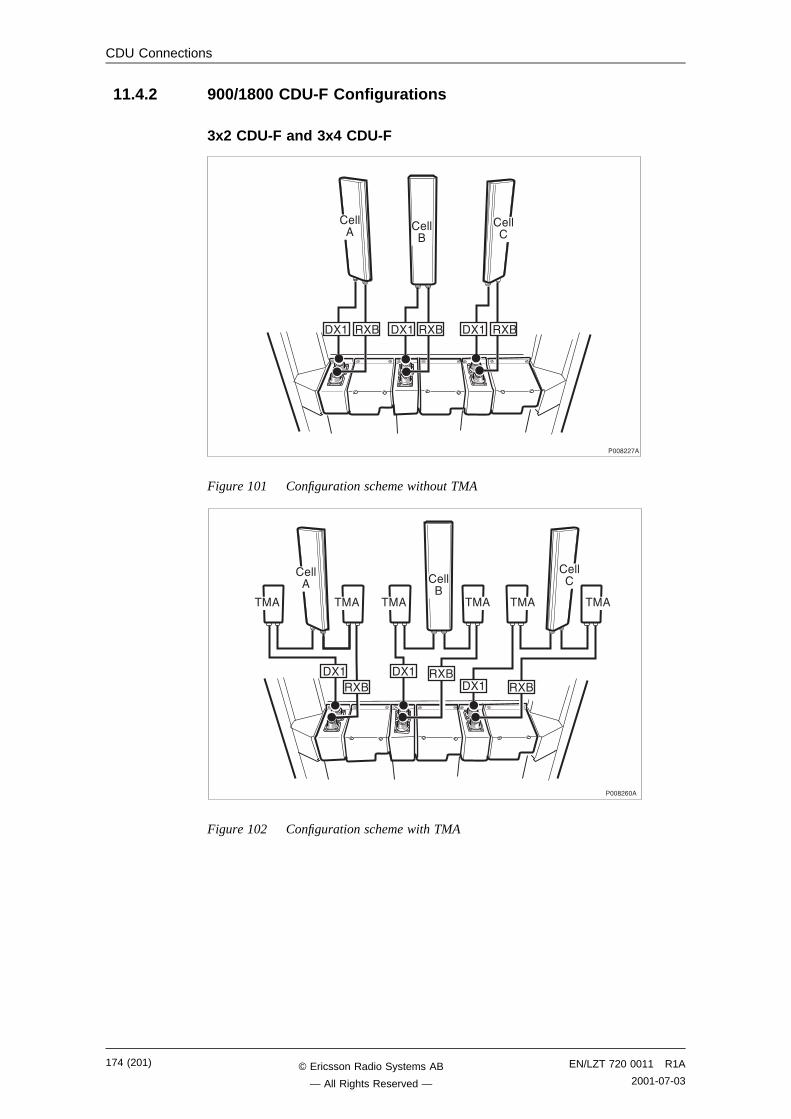
CDU Connections
11.4.2 900/1800 CDU-F Configurations
3x2 CDU-F and 3x4 CDU-F
����,,!�
��� ��� ��� ��� ���
����� ����
������
���
Figure 101 Configuration scheme without TMA
����,-��
���
������
�����
��� ��� ���
�����
���
���
���
�����
��� ������
Figure 102 Configuration scheme with TMA
174 (201) EN/LZT 720 0011 R1A
2001-07-03© Ericsson Radio Systems AB
— All Rights Reserved —
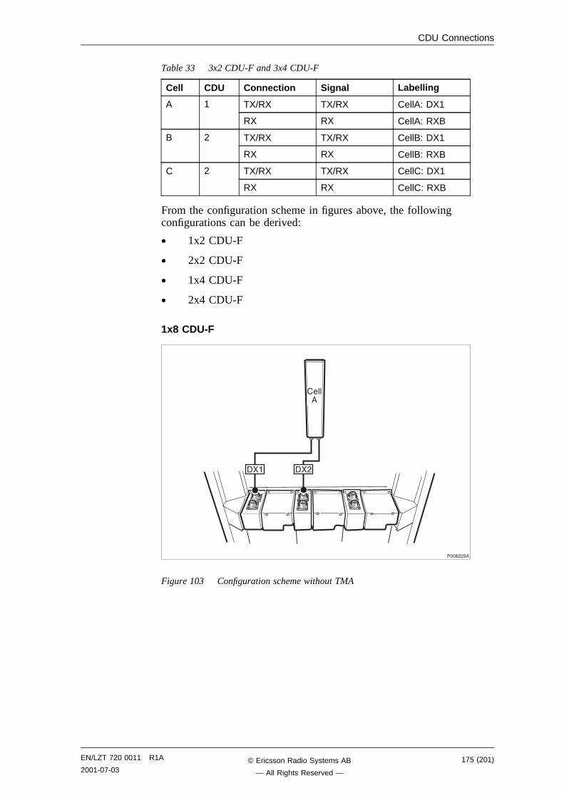
CDU Connections
Table 33 3x2 CDU-F and 3x4 CDU-F
Cell CDU Connection Signal Labelling
TX/RX TX/RX CellA: DX1A 1
RX RX CellA: RXB
TX/RX TX/RX CellB: DX1B 2
RX RX CellB: RXB
TX/RX TX/RX CellC: DX1C 2
RX RX CellC: RXB
From the configuration scheme in figures above, the followingconfigurations can be derived:
• 1x2 CDU-F
• 2x2 CDU-F
• 1x4 CDU-F
• 2x4 CDU-F
1x8 CDU-F
����,,��
��� ��,
�����
Figure 103 Configuration scheme without TMA
EN/LZT 720 0011 R1A
2001-07-03175 (201)© Ericsson Radio Systems AB
— All Rights Reserved —
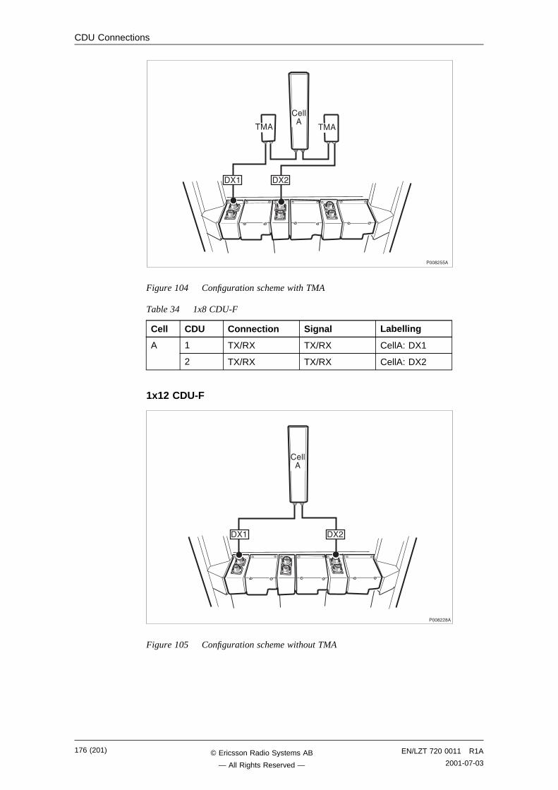
CDU Connections
����,66�
��� ��,
��� ���
�����
Figure 104 Configuration scheme with TMA
Table 34 1x8 CDU-F
Cell CDU Connection Signal Labelling
1 TX/RX TX/RX CellA: DX1A
2 TX/RX TX/RX CellA: DX2
1x12 CDU-F
����,,��
��� ��,
�����
Figure 105 Configuration scheme without TMA
176 (201) EN/LZT 720 0011 R1A
2001-07-03© Ericsson Radio Systems AB
— All Rights Reserved —
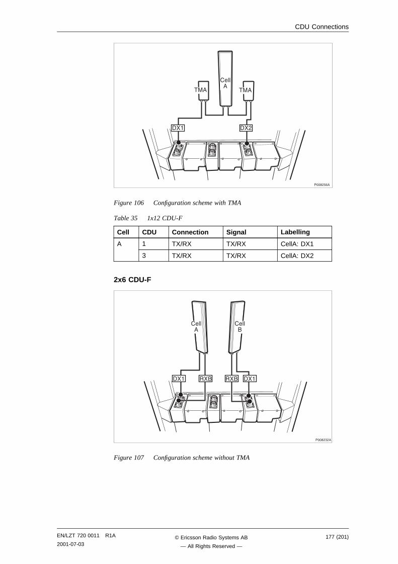
CDU Connections
����,6-�
��� ��,
��� ���
�����
Figure 106 Configuration scheme with TMA
Table 35 1x12 CDU-F
Cell CDU Connection Signal Labelling
1 TX/RX TX/RX CellA: DX1A
3 TX/RX TX/RX CellA: DX2
2x6 CDU-F
����,",�
��� ���
�����
�����
��� ���
Figure 107 Configuration scheme without TMA
EN/LZT 720 0011 R1A
2001-07-03177 (201)© Ericsson Radio Systems AB
— All Rights Reserved —
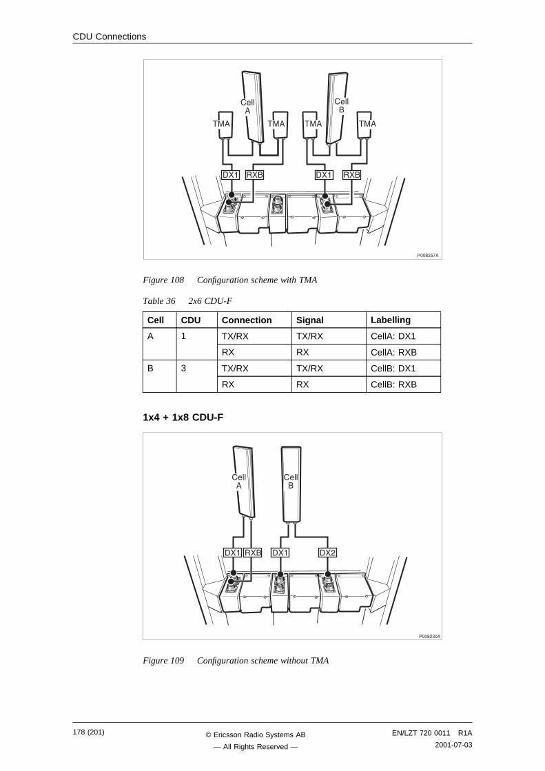
CDU Connections
����,6!�
���
���
�����
���
�����
��� ���
��� ���
���
Figure 108 Configuration scheme with TMA
Table 36 2x6 CDU-F
Cell CDU Connection Signal Labelling
TX/RX TX/RX CellA: DX1A 1
RX RX CellA: RXB
TX/RX TX/RX CellB: DX1B 3
RX RX CellB: RXB
1x4 + 1x8 CDU-F
����,"��
��� ������ ��,
�����
�����
Figure 109 Configuration scheme without TMA
178 (201) EN/LZT 720 0011 R1A
2001-07-03© Ericsson Radio Systems AB
— All Rights Reserved —
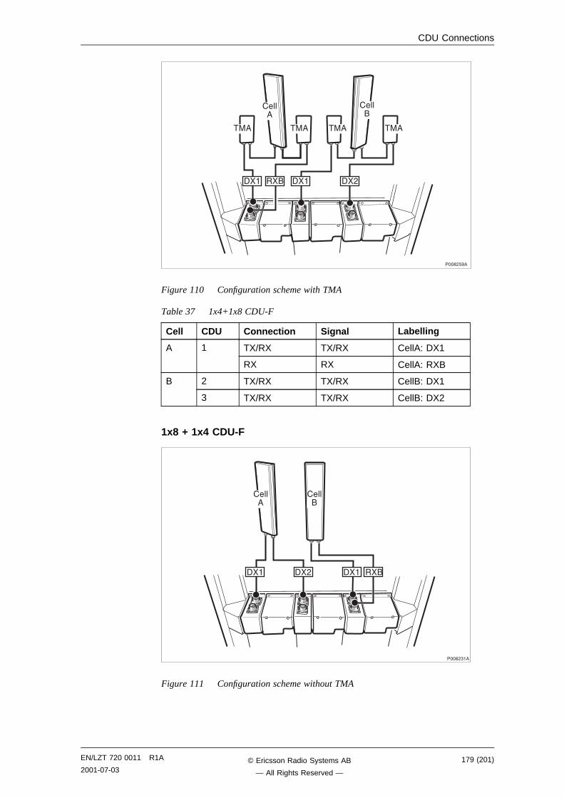
CDU Connections
����,6��
�����
�����
��� ���
��,
���
��� ���
���
���
Figure 110 Configuration scheme with TMA
Table 37 1x4+1x8 CDU-F
Cell CDU Connection Signal Labelling
TX/RX TX/RX CellA: DX1A 1
RX RX CellA: RXB
2 TX/RX TX/RX CellB: DX1B
3 TX/RX TX/RX CellB: DX2
1x8 + 1x4 CDU-F
����,"��
��� ��� �����,
�����
�����
Figure 111 Configuration scheme without TMA
EN/LZT 720 0011 R1A
2001-07-03179 (201)© Ericsson Radio Systems AB
— All Rights Reserved —
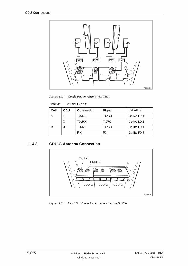
CDU Connections
����,6��
���
���
�����
�����
��� ���
���
���
��,���
Figure 112 Configuration scheme with TMA
Table 38 1x8+1x4 CDU-F
Cell CDU Connection Signal Labelling
1 TX/RX TX/RX CellA: DX1A
2 TX/RX TX/RX CellA: DX2
TX/RX TX/RX CellB: DX1B 3
RX RX CellB: RXB
11.4.3 CDU-G Antenna Connection
����"6!�
�� /A �� /A �� /A
��=������=���,
Figure 113 CDU-G antenna feeder connectors, RBS 2206
180 (201) EN/LZT 720 0011 R1A
2001-07-03© Ericsson Radio Systems AB
— All Rights Reserved —
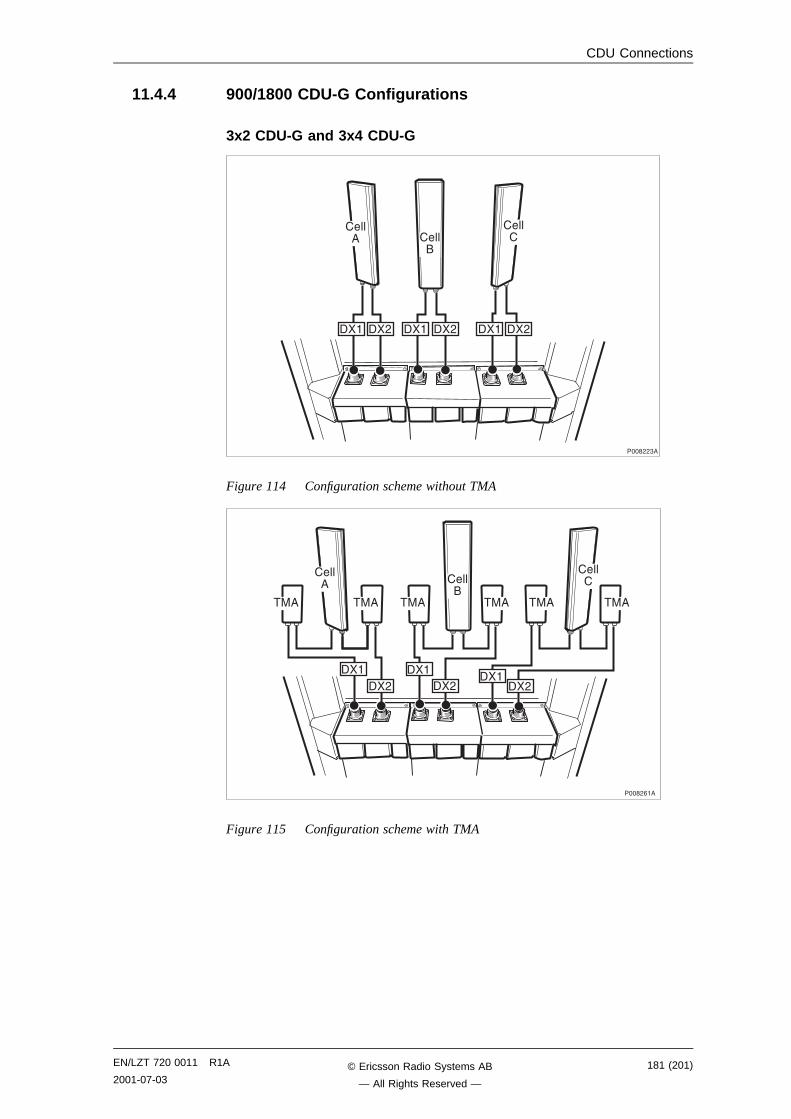
CDU Connections
11.4.4 900/1800 CDU-G Configurations
3x2 CDU-G and 3x4 CDU-G
����� ����
�
�����
����,,"�
��� ��, ��� ��, ��� ��,
Figure 114 Configuration scheme without TMA
����,-��
���
��,
�����
��� ��� ���
�����
��� ���
�����
�����,
�����,
���
Figure 115 Configuration scheme with TMA
EN/LZT 720 0011 R1A
2001-07-03181 (201)© Ericsson Radio Systems AB
— All Rights Reserved —
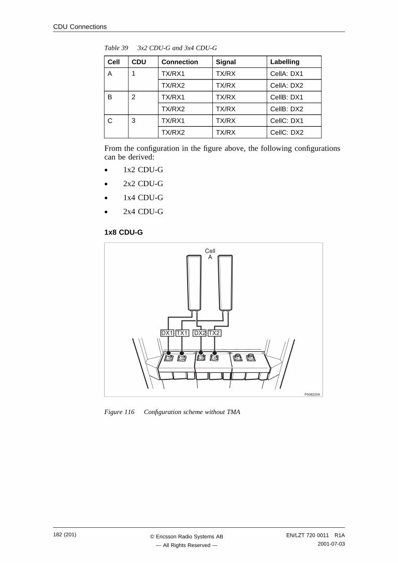
CDU Connections
Table 39 3x2 CDU-G and 3x4 CDU-G
Cell CDU Connection Signal Labelling
TX/RX1 TX/RX CellA: DX1A 1
TX/RX2 TX/RX CellA: DX2
TX/RX1 TX/RX CellB: DX1B 2
TX/RX2 TX/RX CellB: DX2
TX/RX1 TX/RX CellC: DX1C 3
TX/RX2 TX/RX CellC: DX2
From the configuration in the figure above, the following configurationscan be derived:
• 1x2 CDU-G
• 2x2 CDU-G
• 1x4 CDU-G
• 2x4 CDU-G
1x8 CDU-G
����,,6�
��� ���
�����
��,��,
Figure 116 Configuration scheme without TMA
182 (201) EN/LZT 720 0011 R1A
2001-07-03© Ericsson Radio Systems AB
— All Rights Reserved —
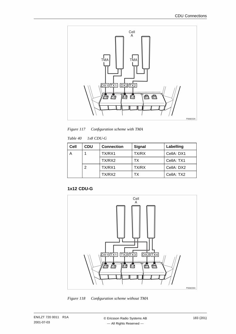
CDU Connections
����,""�
��� ���
�����
��,��,
��� ���
Figure 117 Configuration scheme with TMA
Table 40 1x8 CDU-G
Cell CDU Connection Signal Labelling
TX/RX1 TX/RX CellA: DX11
TX/RX2 TX CellA: TX1
TX/RX1 TX/RX CellA: DX2
A
2
TX/RX2 TX CellA: TX2
1x12 CDU-G
����,,-�
��� ���
�����
��"��, ��, ���
Figure 118 Configuration scheme without TMA
EN/LZT 720 0011 R1A
2001-07-03183 (201)© Ericsson Radio Systems AB
— All Rights Reserved —
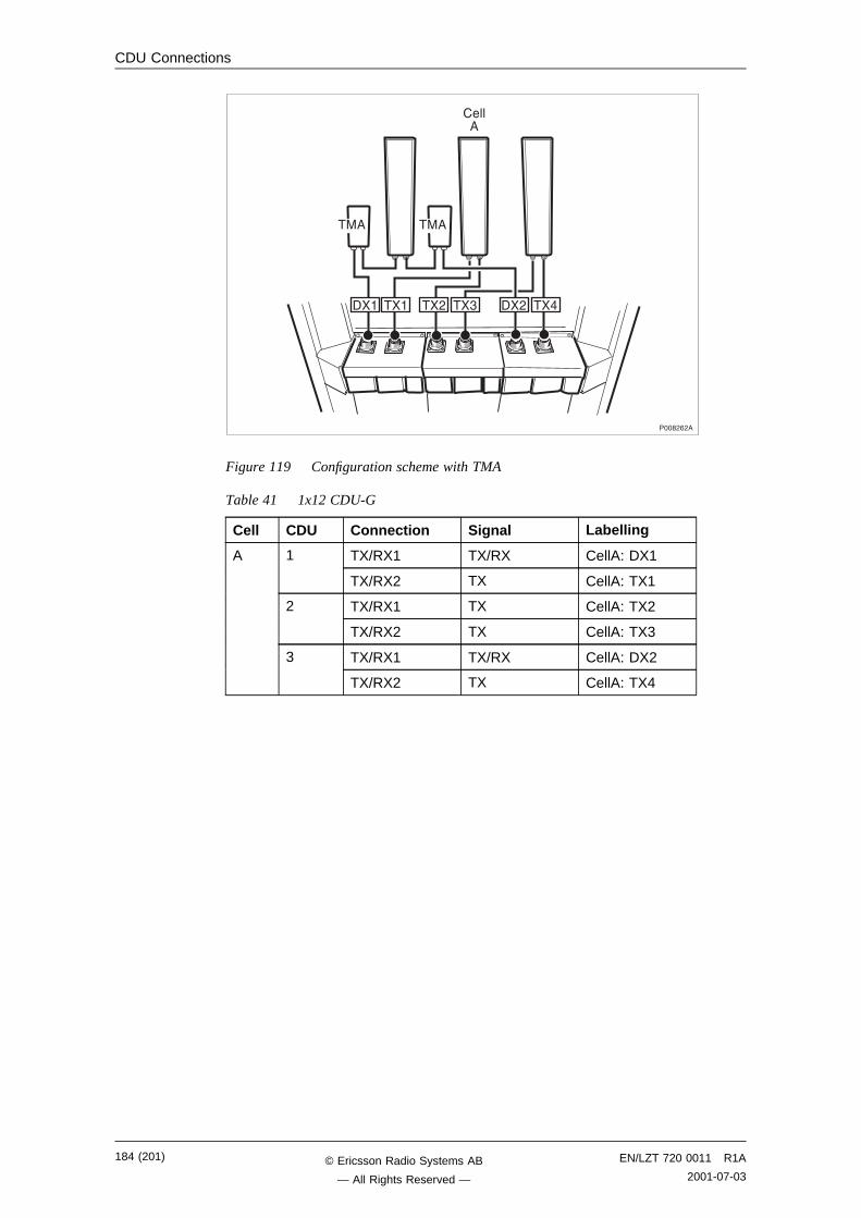
CDU Connections
����,-,�
��� ��,
���
��� ��, ��" ���
�����
���
Figure 119 Configuration scheme with TMA
Table 41 1x12 CDU-G
Cell CDU Connection Signal Labelling
TX/RX1 TX/RX CellA: DX11
TX/RX2 TX CellA: TX1
TX/RX1 TX CellA: TX22
TX/RX2 TX CellA: TX3
TX/RX1 TX/RX CellA: DX2
A
3
TX/RX2 TX CellA: TX4
184 (201) EN/LZT 720 0011 R1A
2001-07-03© Ericsson Radio Systems AB
— All Rights Reserved —
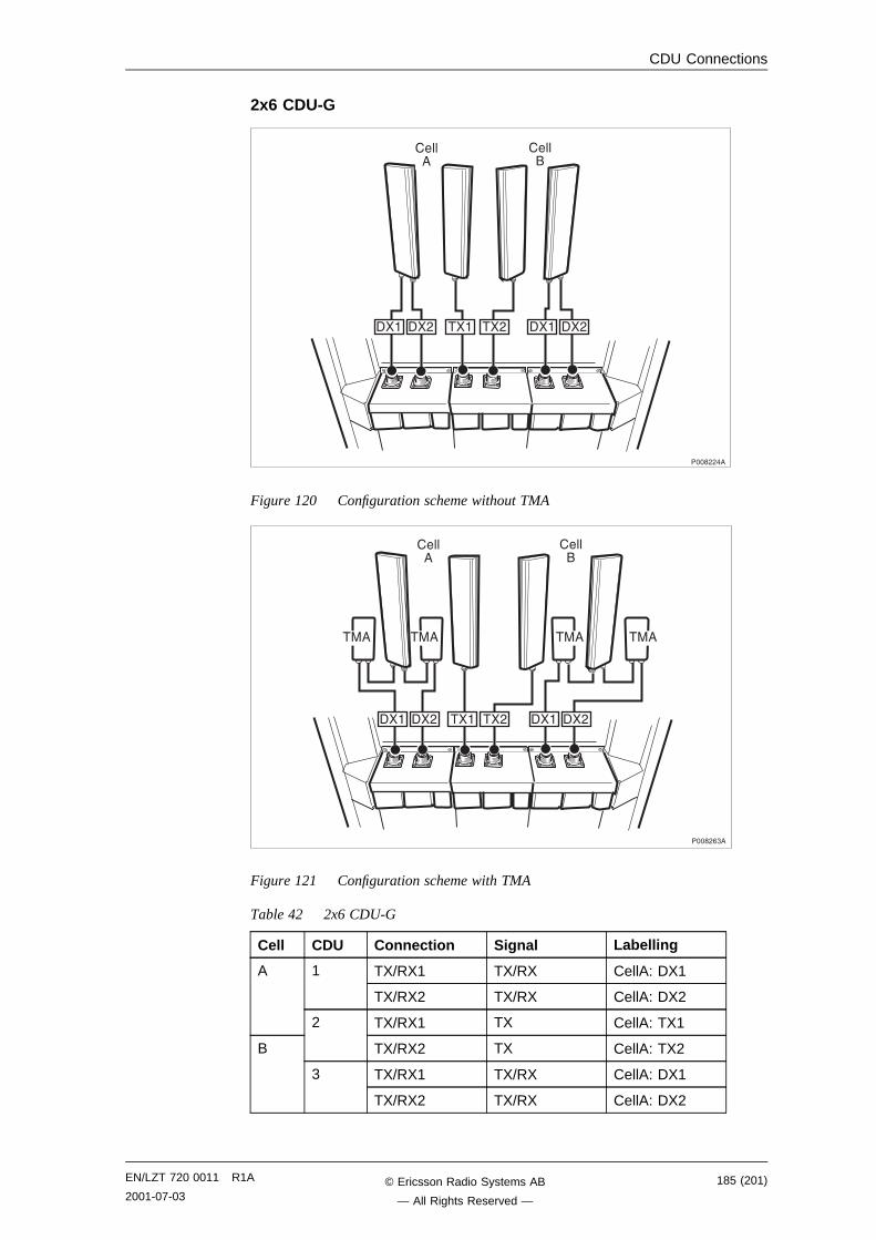
CDU Connections
2x6 CDU-G
����,,��
�����
��� ��, ��� ��,
�����
��� ��,
Figure 120 Configuration scheme without TMA
����,-"�
���
���
�����
�����
��, ��� ��,
��� ���
��,���
���
Figure 121 Configuration scheme with TMA
Table 42 2x6 CDU-G
Cell CDU Connection Signal Labelling
TX/RX1 TX/RX CellA: DX11
TX/RX2 TX/RX CellA: DX2
A
TX/RX1 TX CellA: TX12
TX/RX2 TX CellA: TX2
TX/RX1 TX/RX CellA: DX1
B
3
TX/RX2 TX/RX CellA: DX2
EN/LZT 720 0011 R1A
2001-07-03185 (201)© Ericsson Radio Systems AB
— All Rights Reserved —

CDU Connections
This page is intentionally left blank
186 (201) EN/LZT 720 0011 R1A
2001-07-03© Ericsson Radio Systems AB
— All Rights Reserved —
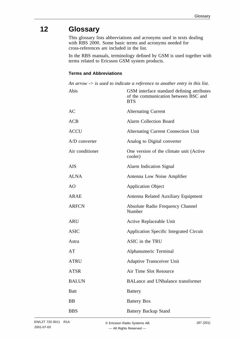
Glossary
12 GlossaryThis glossary lists abbreviations and acronyms used in texts dealingwith RBS 2000. Some basic terms and acronyms needed forcross-references are included in the list.
In the RBS manuals, terminology defined by GSM is used together withterms related to Ericsson GSM system products.
Terms and Abbreviations
An arrow -> is used to indicate a reference to another entry in this list.
Abis GSM interface standard defining attributesof the communication between BSC andBTS
AC Alternating Current
ACB Alarm Collection Board
ACCU Alternating Current Connection Unit
A/D converter Analog to Digital converter
Air conditioner One version of the climate unit (Activecooler)
AIS Alarm Indication Signal
ALNA Antenna Low Noise Amplifier
AO Application Object
ARAE Antenna Related Auxiliary Equipment
ARFCN Absolute Radio Frequency ChannelNumber
ARU Active Replaceable Unit
ASIC Application Specific Integrated Circuit
Astra ASIC in the TRU
AT Alphanumeric Terminal
ATRU Adaptive Transceiver Unit
ATSR Air Time Slot Resource
BALUN BALance and UNbalance transformer
Batt Battery
BB Battery Box
BBS Battery Backup Stand
EN/LZT 720 0011 R1A
2001-07-03187 (201)© Ericsson Radio Systems AB
— All Rights Reserved —
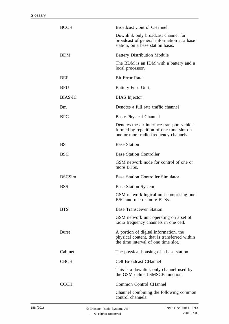
Glossary
BCCH Broadcast Control CHannel
Downlink only broadcast channel forbroadcast of general information at a basestation, on a base station basis.
BDM Battery Distribution Module
The BDM is an IDM with a battery and alocal processor.
BER Bit Error Rate
BFU Battery Fuse Unit
BIAS-IC BIAS Injector
Bm Denotes a full rate traffic channel
BPC Basic Physical Channel
Denotes the air interface transport vehicleformed by repetition of one time slot onone or more radio frequency channels.
BS Base Station
BSC Base Station Controller
GSM network node for control of one ormore BTSs.
BSCSim Base Station Controller Simulator
BSS Base Station System
GSM network logical unit comprising oneBSC and one or more BTSs.
BTS Base Transceiver Station
GSM network unit operating on a set ofradio frequency channels in one cell.
Burst A portion of digital information, thephysical content, that is transferred withinthe time interval of one time slot.
Cabinet The physical housing of a base station
CBCH Cell Broadcast CHannel
This is a downlink only channel used bythe GSM defined SMSCB function.
CCCH Common Control CHannel
Channel combining the following commoncontrol channels:
188 (201) EN/LZT 720 0011 R1A
2001-07-03© Ericsson Radio Systems AB
— All Rights Reserved —
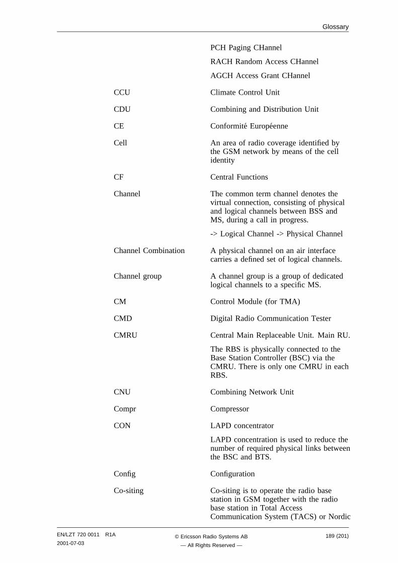
Glossary
PCH Paging CHannel
RACH Random Access CHannel
AGCH Access Grant CHannel
CCU Climate Control Unit
CDU Combining and Distribution Unit
CE Conformite Europeenne
Cell An area of radio coverage identified bythe GSM network by means of the cellidentity
CF Central Functions
Channel The common term channel denotes thevirtual connection, consisting of physicaland logical channels between BSS andMS, during a call in progress.
-> Logical Channel -> Physical Channel
Channel Combination A physical channel on an air interfacecarries a defined set of logical channels.
Channel group A channel group is a group of dedicatedlogical channels to a specific MS.
CM Control Module (for TMA)
CMD Digital Radio Communication Tester
CMRU Central Main Replaceable Unit. Main RU.
The RBS is physically connected to theBase Station Controller (BSC) via theCMRU. There is only one CMRU in eachRBS.
CNU Combining Network Unit
Compr Compressor
CON LAPD concentrator
LAPD concentration is used to reduce thenumber of required physical links betweenthe BSC and BTS.
Config Configuration
Co-siting Co-siting is to operate the radio basestation in GSM together with the radiobase station in Total AccessCommunication System (TACS) or Nordic
EN/LZT 720 0011 R1A
2001-07-03189 (201)© Ericsson Radio Systems AB
— All Rights Reserved —
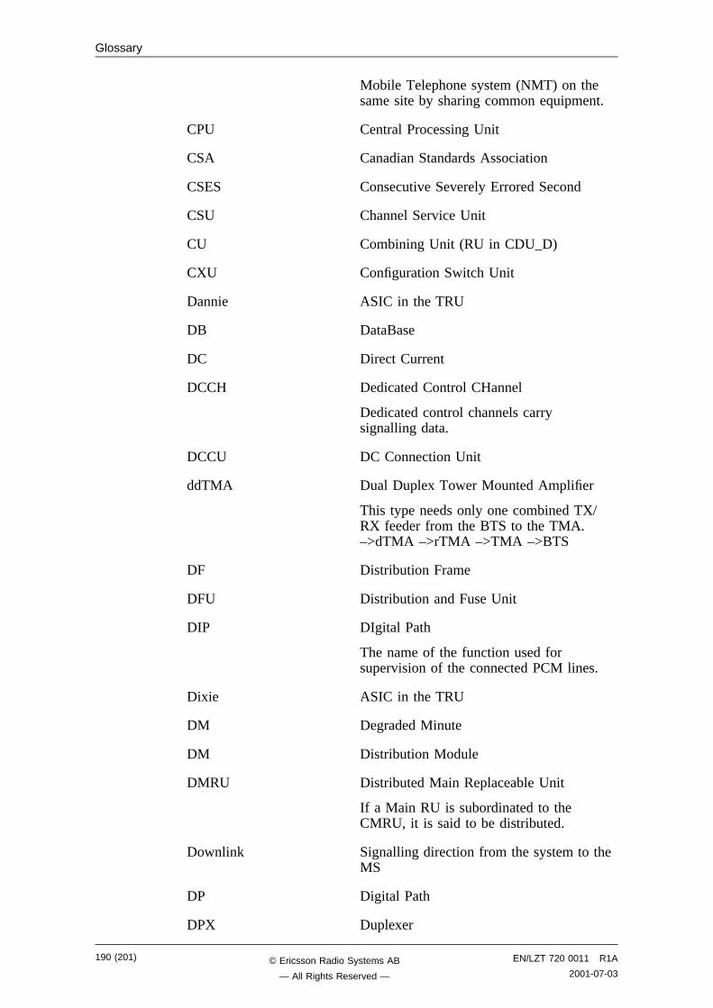
Glossary
Mobile Telephone system (NMT) on thesame site by sharing common equipment.
CPU Central Processing Unit
CSA Canadian Standards Association
CSES Consecutive Severely Errored Second
CSU Channel Service Unit
CU Combining Unit (RU in CDU_D)
CXU Configuration Switch Unit
Dannie ASIC in the TRU
DB DataBase
DC Direct Current
DCCH Dedicated Control CHannel
Dedicated control channels carrysignalling data.
DCCU DC Connection Unit
ddTMA Dual Duplex Tower Mounted Amplifier
This type needs only one combined TX/RX feeder from the BTS to the TMA.–>dTMA –>rTMA –>TMA –>BTS
DF Distribution Frame
DFU Distribution and Fuse Unit
DIP DIgital Path
The name of the function used forsupervision of the connected PCM lines.
Dixie ASIC in the TRU
DM Degraded Minute
DM Distribution Module
DMRU Distributed Main Replaceable Unit
If a Main RU is subordinated to theCMRU, it is said to be distributed.
Downlink Signalling direction from the system to theMS
DP Digital Path
DPX Duplexer
190 (201) EN/LZT 720 0011 R1A
2001-07-03© Ericsson Radio Systems AB
— All Rights Reserved —
Glossary
DS1 Digital Signal level 1 (1544 kbit/s)
DSP Digital Signal Processor
DT Data Transcript
dTMA Duplex TMA
dTMA is similar to the old ALNA exceptfor different characteristics. –>ddTMA–>rTMA –>TMA
dTRU double Transceiver Unit
DU Distribution Unit (RU in CDU-D)
DX Direct Exchange
DXC Digital Cross Connector
DXU Distribution Switch Unit
DXX Ericsson Cellular Transmission Systemincluding NMS
E1 Short for G.703 2048 kbit/s PCM link
E-GSM Extended GSM
EACU External Alarm Connection Unit
ECU Energy Control Unit
EC1 External Condition Map Class 1
EC2 External Condition Map Class 2
EDGE Enhanced Data rate for Global Evolution
EDT Electrical Down Tilt
EEPROM Electrically Erasable ProgrammableRead-Only Memory
EMC Electro Magnetic Compatibility
EMF ElectroMotive Force
EMI Electromagnetic Interference
ENV Environmental
ES Errored Second
ESB External Synchronization Bus
ESD ElectroStatic Discharge
ESO Ericsson Support Office
EN/LZT 720 0011 R1A
2001-07-03191 (201)© Ericsson Radio Systems AB
— All Rights Reserved —
Glossary
EXT External
FACCH Fast Associated Control CHannel
Main signalling channel in associationwith a TCH.
FCC Federal Communications Commission
FCCH Frequency Correction CHannel
FCOMB Filter COMBiner
FCU Fan Control Unit
FDL Facility Data Link
FER Frame Erasure Ratio
FIU Fan Interface Unit
FS Function Specification
FSC Field Support Centre
FU Filter Unit (RU in CDU-D)
FUd Filter Unit with duplexer (RU in CDU-D)
FXU Future Expansion Unit
G01 MO model for RBS 200
G12 MO model for RBS 2000
G.703 CCITT Standard for transmission
GPRS General Packet Radio Services
GSM Global System for Mobile communications
International standard for a TDMA digitalmobile communication system. Originally,GSM was an abbreviation for GroupSpecial Mobile, which is a Europeanmobile telecommunication interest group,established in 1982.
HCOMB Hybrid COMBiner
HDLC High level Data Link Control
HDSL High bit rate Digital Subscriber Line
Heat Exchanger One version of the climate unit
HEU Heat Exchanger Unit
HLIN High Level IN
192 (201) EN/LZT 720 0011 R1A
2001-07-03© Ericsson Radio Systems AB
— All Rights Reserved —
Glossary
HLOUT High Level OUT
HMS Heat Management System
Hum Humidity
HW HardWare
HWU Hardware Unit
An HWU consists of one or more SEs. AnHWU is a functional unit within the RBS.The HWU is either active (equipped with aprocessor) or passive (without processor).
IC Integrated Circuit
ID IDentification
IDB Installation Data Base
IDM Internal Distribution Module
IEC International Electric Commission
IMSI International Mobile Subscriber Identity
INIT Initial
INT Internal
IOG Input/Output Group
IOM Internal Operation and Maintenance bus
IR InfraRed
IS Interface Switch
IWD InterWork Description
I1A Internal Fault Map Class 1A
I1B Internal Fault Map Class 1B
I2A Internal Fault Map Class 2A
JTC Joint Technical Committee
LAPD Link Access Procedures on D-channel
LAPD is the data link layer (layer 2)protocol used for communication betweenthe BSC and the BTS on the Abisinterface.
Abis layer 2 is sometimes usedsynonymously with LAPD.
EN/LZT 720 0011 R1A
2001-07-03193 (201)© Ericsson Radio Systems AB
— All Rights Reserved —
Glossary
LBO Line Build Out
LED Light Emitting Diode
LLB Line Loop Back
LNA Low Noise Amplifier
Local bus The local bus offers communicationbetween a central main RU (DXU) anddistributed main RUs (TRU and ECU).
Local mode When the RU is in RU mode Local it isnot prepared for BSC communication.
Local/Remote switch Using the Local/Remote switch, anoperator orders the RU to enter Local orRemote mode.
LOF Loss Of Frame
Logical Channel A logical channel represents a specifiedportion of the information carryingcapacity of a physical channel.
GSM defines two major categories oflogical channels:
TCHs Traffic CHannels, for speech oruser data
CCHs Control CHannels, for controlsignalling.
-> Physical Channel -> ChannelCombination
Logical RU A unit which can be referred to, but is nota single physical unit. There are threedifferent kinds of logical RUs:
1. Buses
2. Antennas
3. Environment
LOS Loss Of Signal
MAC Medium Access Controller
Magazine A magazine is a reserved space in thecabinet, which may hold one or more RUs.
Main RU A main replaceable unit is a replaceableunit that contains one or more processors,to which software can be downloadedfrom the BSC.
MHS Modification Handling System
194 (201) EN/LZT 720 0011 R1A
2001-07-03© Ericsson Radio Systems AB
— All Rights Reserved —
Glossary
Ericsson trouble report database
MMI Man-Machine Interface
MO Managed Object
MR Measurement Receiver
MS Mobile Station
MSC Mobile services Switching Centre
GSM network unit for switching, routingand controlling calls to and from thePublic Switched Telephone Network(PSTN) and other networks.
MSTP Mobile Station Test Point
Multidrop Two or more RBSs are connected in achain to the same transmission system.All the relevant timeslots are dropped outby each RBS. (This function is sometimecalled cascading.)
NEBS Network Equipment Building System
NMS Ericsson Network Management System inDXX
Nominal Power The nominal power is the power leveldefined when configuring the transceiver.
N terminal Neutral terminal in a AC mains connection
O&M Operation and Maintenance
General term for activities such asconfiguration, utilization of channels(frequency bands), cell planning, systemsupervision, hardware and softwaremaintenance, subscriber administration,and so forth.
OMC Operation and Maintenance Centre
OML Operation and Maintenance Link
Layer 2 communication link for operationand maintenance services on Abis.
OMT Operation and Maintenance Terminal
The OMT is a terminal that supportsfunctions for handling the RBS on site.The terminal can be a portable PC.
Operation Operation is the normal, everyday runningof the RBS with full functionality.
EN/LZT 720 0011 R1A
2001-07-03195 (201)© Ericsson Radio Systems AB
— All Rights Reserved —
Glossary
OPI OPerational Instructions
OVP OverVoltage Protection
OXU Space for Optional Expansion
P-GSM Primary GSM
Passive RU A passive replaceable unit has a very lowlevel of intelligence and is independent ofthe processor system.
PCAT Product CATalogue
A web-based ordering system inEricsson’s intranet.
PCH Paging CHannel
Downlink only subchannel of CCCH forsystem paging of MSs.
-> CCCH
PCM Pulse Code Modulation
PCU Packet Control Unit
PE terminal Protective Earth terminal in a AC mainsconnection
PFWD Power Forward
Physical Channel An air interface physical channel carriesone or more logical channels. A physicalchannel uses a combination of frequencyand time division multiplexing and isdefined as a sequence of radio frequencychannels and time slots.
-> TDMA frame -> Logical channel
PIN Personal Identification Number
PLB Payload Loop Back
PLMN Public Land Mobile Network
A network, established and operated by anadministration or its licensed operator(s),for the specific purpose of providing landmobile communication services to thepublic. It provides communicationpossibilities for mobile users. Forcommunication between mobile and fixedusers, interworking with a fixed network isnecessary.
PPE Personal Protective Equipment
196 (201) EN/LZT 720 0011 R1A
2001-07-03© Ericsson Radio Systems AB
— All Rights Reserved —
Glossary
PREFL Power Reflected
PSU Power Supply Unit
PWU Power Unit
RACH Random Access CHannel
Uplink only subchannel of CCCH for MSrequest for allocation of a dedicatedchannel.
-> CCCH
RAI Remote Alarm Indication
RAM Random Access Memory
RBER Radio Bit Error Ratio
RBS Radio Base Station
All equipment forming one or moreEricsson base stations.
->BTS
RCB Radio Connection Box
RD Receive Data
Remote mode When the RU is in RU mode Remote, alink is established between the BCS andthe central main RU.
RF Radio Frequency
RFCH Radio Frequency CHannel
A radio frequency carrier with itsassociated bandwidth.
RFTL Radio Frequency Test Loop
RLC Repair Logistic Centre
R-state Release state
RS232 American standard for term/MODEMinterconnection
rTMA Receiver TMA
rTMA has no duplexers. It is used foramplification of the RX signal. –>ddTMA–>dTMA –>TMA
RU Replacement Unit
EN/LZT 720 0011 R1A
2001-07-03197 (201)© Ericsson Radio Systems AB
— All Rights Reserved —
Glossary
An RU consists of one or more HWUs.An RU may be replaced by another RU ofthe same type. The RU is the smallestunit that can be handled on site.
RX Receiver
RX1 Receiver antenna branch 1
RX2 Receiver antenna branch 2
RXA Receiver antenna branch A
RXB Receiver antenna branch B
RXD Receiver Divider
RXDA Receiver Divider Amplifier
RXLEV Measure of signal strength as defined inGSM 05.08:8.1.4
RXQUAL Measure of signal quality as defined inGSM 05.08:8.2.4
SACCH Slow Associated Control CHannel
SCH Synchronization CHannel
SDCCH Stand alone Dedicated Control CHannel
Main dedicated signalling channel on theair interface, mainly used for call locatingand establishment.
SCU Switching and Combining Unit
SE Supervised Entity
SES Severely Errored Second
SIG Signalling
SIM Subscriber Identity Module
SMS Short Message Service (point to point)
A short message, up to 160 alphanumericcharacters long, can be sent to or from anMS (point to point).
SO Service Object
SS Swedish Standard
Sub-RU A sub-replaceable unit is alwaysconnected to a superior Main RU. Thisconnection is used for example for
198 (201) EN/LZT 720 0011 R1A
2001-07-03© Ericsson Radio Systems AB
— All Rights Reserved —
Glossary
retrieval of the RU identity. A sub-RUnormally does not have a processor. Notethat an RU with a processor, which cannotbe loaded, is classified as a sub-RU.
SVS System Voltage Sensor
SW SoftWare
SWR Standing Wave Ratio
SYNC Synchronous
T1 Transmission facility for DS1 (1544 kbit/s)
TA Timing Advance
A signal sent by the BTS to the MS whichthe MS uses to advance its timing oftransmissions to the BTS to compensatefor propagation delay.
TC Transaction Capabilities
TCH Traffic CHannel
The traffic channels carry either encodedspeech or user data.
TCH SIG Traffic CHannel Signalling
TD Transmit Data
TDMA Time Division Multiple Access
Multiplexing of several channels in acommon frequency band. Each channel isassigned a certain time division, a timeslot.
TDMA frame GSM air interface time frame comprisingeight time slots
TDR Time Domain Reflectometer
TEI Terminal Endpoint Identifier
TEI is an identification code carried by aLAPD frame as a terminal connectionendpoint within a Service Access Point(SAP).
TEMS TEst Mobile Station
TF Timing Function
TG Transceiver Group
EN/LZT 720 0011 R1A
2001-07-03199 (201)© Ericsson Radio Systems AB
— All Rights Reserved —
Glossary
Timing bus The timing bus carries air timinginformation from the timing unit in theDXU to the TRUs.
TM Transport Module
The Transport module is non-RBSequipment belonging to the transportnetwork.
TMA Tower Mounted Amplifier
There are three types of TMAs: dTMA,rTMA and ddTMA. –>dTMA –>rTMA–>ddTMA
TMA CM Tower Mounted Amplifier Control Module
TN Timeslot Number
TN O&M Transport Network operation andMaintenance (in general)
Tora ASIC in the TRU
TRA Transcoder Rate Adapter
The TRA Unit performs transcoding ofspeech information and rate adaption ofdata information.
Tracy ASIC in the TRU
TRS Transceiver System
TRU Transceiver Unit
TRX Transceiver
TRXC Transceiver Controller
TS Time Slot
A 0.577 ms period (TDMA frame subunit)corresponding to 156.25 raw bits ofinformation. The eight time slots of eachTDMA frame are numbered 0...7.
-> Burst
TT Total Time
TU Timing Unit
TX Transmitter
TXA Transmitter Antenna A
TXB Transmitter Antenna B
200 (201) EN/LZT 720 0011 R1A
2001-07-03© Ericsson Radio Systems AB
— All Rights Reserved —
Glossary
TXBP Transmitter BandPass filter
UAS Unavailable Seconds
UL Underwriter Laboratories
Uplink Signalling direction from the MS to thesystem
UPS Uninterrupted Power Supply
VCO Voltage Controlled Oscillator
VSWR Voltage Standing Wave Ratio RF signalmeasure. The quotient betweentransmitted and reflected voltage.
X-bus The X-bus carries transmit air data framesbetween transceivers.
Y-link The interface between the DXU and eachDSP System in Core based TRUs
EN/LZT 720 0011 R1A
2001-07-03201 (201)© Ericsson Radio Systems AB
— All Rights Reserved —


���
����
�
��������
���� ������������
��������������� ���
����� �!�����"���"#

�������� � ��� �
�� ����
��� ����� ��������
EN/LZT 720 0012 R1A © Ericsson Radio Systems AB 1 (59)
2001-06-06 - All Rights Reserved -

This page is intentionally left blank
2 (59) © Ericsson Radio Systems AB EN/LZT 720 0012 R1A
- All Rights Reserved - 2001-06-06
Spare Parts Catalogue
��� ����� �������� © Ericsson Radio Systems AB - All Rights Reserved -
EN/LZT 720 0012 R1A © Ericsson Radio Systems AB 3 (59)
2001-06-06 - All Rights Reserved -
Spare Parts Catalogue
Due to continued progress in methodology, design and manufactoring the contents of this documentare subject to revision without notice.
4 (59) © Ericsson Radio Systems AB EN/LZT 720 0012 R1A
- All Rights Reserved - 2001-06-06

���� ���
�� ��� � � � � � � � � � � � � � � � � � � � � � � � � � � � � � � � � � � � � � � � � � � � � � � �
Release History . . . . . . . . . . . . . . . . . . . . . . . . . . . . . . . . . . . . . . . . . 8
��� ����� ���������� ��� �� ���� � � � � � � � � � � � � � � � � � � � � � � � � � � � � �
General Information . . . . . . . . . . . . . . . . . . . . . . . . . . . . . . . . . . . . . . . 9
� ���� � !� �����"� # ��� ����� ��� ������ � ���$ � � � � � � � � � � � � � �%%
Basic Units . . . . . . . . . . . . . . . . . . . . . . . . . . . . . . . . . . . . . . . . . . . .13
900 MHz Units . . . . . . . . . . . . . . . . . . . . . . . . . . . . . . . . . . . . . . . . . .15
1800 MHz Units . . . . . . . . . . . . . . . . . . . . . . . . . . . . . . . . . . . . . . . . .17
1900 MHz Units . . . . . . . . . . . . . . . . . . . . . . . . . . . . . . . . . . . . . . . . .19
� ���� � !&�� � �����"� # ��� ����� ��� ������ � ���$ � � � � � � � � � � ��%
Basic Units . . . . . . . . . . . . . . . . . . . . . . . . . . . . . . . . . . . . . . . . . . . .23
Cabinet Parts . . . . . . . . . . . . . . . . . . . . . . . . . . . . . . . . . . . . . . . . . . .25
Common Cables . . . . . . . . . . . . . . . . . . . . . . . . . . . . . . . . . . . . . . . . .27
'�� � ()����"� ������ � � � � � � � � � � � � � � � � � � � � � � � � � � � � � � � � � � � � ���
Miscellaneous Parts . . . . . . . . . . . . . . . . . . . . . . . . . . . . . . . . . . . . . . .31
ACCU/DCCU/VDC-filter . . . . . . . . . . . . . . . . . . . . . . . . . . . . . . . . . . . . .33
Cabinet Parts . . . . . . . . . . . . . . . . . . . . . . . . . . . . . . . . . . . . . . . . . . .35
CNU connections. . . . . . . . . . . . . . . . . . . . . . . . . . . . . . . . . . . . . . . . .37
Cables. . . . . . . . . . . . . . . . . . . . . . . . . . . . . . . . . . . . . . . . . . . . . . .39
Coaxial Cables CDU-G without hybrid . . . . . . . . . . . . . . . . . . . . . . . . . . . . .43
Coaxial Cables CDU-G with hybrid . . . . . . . . . . . . . . . . . . . . . . . . . . . . . . .45
Coaxial Cables CDU-F. . . . . . . . . . . . . . . . . . . . . . . . . . . . . . . . . . . . . .47
Dummies . . . . . . . . . . . . . . . . . . . . . . . . . . . . . . . . . . . . . . . . . . . . .49
Packing . . . . . . . . . . . . . . . . . . . . . . . . . . . . . . . . . . . . . . . . . . . . . .51
� ���� �� *��� ��+� ����� � � � � � � � � � � � � � � � � � � � � � � � � � � � � � � � �,-
&�� ����� .� /� � � � � � � � � � � � � � � � � � � � � � � � � � � � � � � � � � � � � � � � �,�
EN/LZT 720 0012 R1A © Ericsson Radio Systems AB 5 (59)
2001-06-06 - All Rights Reserved -

This page is intentionally left blank
6 (59) © Ericsson Radio Systems AB EN/LZT 720 0012 R1A
- All Rights Reserved - 2001-06-06
Preface
�� ���
This catalogue is a complement to the Maintenance Manual and provides the information necessaryto order replaceable parts. This information is useful for the general planning of a maintenance organ-isation and in building up a spare parts stock.
The main target groups are:
• Field Technichians
• Technical Administrators
������ � 0���� ������� 1�"����
The user documentation for the RBS 2206 consists of customer manuals divided up to suit differentprocess events. The ������� ����� contains the following information for each manual:
• Short description
• Recommended target group
• Product number
For more information about the RBS 2000 customer documentation library, see:
�� ���� ������� ����� ��� ��� ��
EN/LZT 720 0012 R1A © Ericsson Radio Systems AB 7 (59)
2001-06-06 - All Rights Reserved -
Preface
� � �� 2������
In addition to editorial changes, such as corrections of spelling, grammar and layout, the followingchanges have been made for each release. Only the three last R-states are listed below.
8 (59) © Ericsson Radio Systems AB EN/LZT 720 0012 R1A
- All Rights Reserved - 2001-06-06
Spare Parts Philosophy for RBS 2000
��� ����� ���������� ��� �� ����
The specifying and classifying of spare parts is done during the service preparation process which isa part of the industrialization process. The result is a spare part list containing three classes of spareparts:
• Recommended for customer stock. Intended to be replaced on site and intended to be repaired atEricsson Repair Center or by the Local Service Organisation (code = U)
• Recommended for customer stock. Intended to be replaced on site or at local shop and intended tobe disposed after consumption (code = R).
• Not recommended for customer stock. The parts are available when needed (code = A).
The spare parts catalogue is adapted to this structure.
The dimensioning and recommendation of spare parts will not follow the principle one-of-each-board-in-use unless the customer expressly so insists.
The dimensioning and recommendation of spare part stocks is and will be done with a computer-basedcalculation model for BTS equipment.
The tool is working with the parameters:
• Product reliability (MTBF)
• Spare part delivery lead time or repair turn around time.
• Chosen service level (Spare Part Management).
• The spare part structure.
• Quantity of each unit in operation to be supported by the specific stock.
• The probability of shortage.
� � ��� .����������
The catalogue is divided into separate chapters, depending on recommendations (classifications).
Position numbers put in brackets ( ) are associated parts, not necessary shown in illustrations. Positionnumbers with letters, like 3A, 3B are alternative products. New products are indicated by a #-sign infront of the position number.
Parts without Product number may be shown on illustrations, but are not recommended for customerstock, or may be included in a Spare Parts Set (and not separate orderable). If a reference to anotherchapter is given, more information will be found there.
EN/LZT 720 0012 R1A © Ericsson Radio Systems AB 9 (59)
2001-06-06 - All Rights Reserved -
Spare Parts Philosophy for RBS 2000
��� ����� '� ���� ( � ��3
Please use the Regional Ericsson Company, else:
Ericsson Radio Systems AB
SG/ERA/GV/DP
Customer Support Services, Strategic Supply Management
S-164 80 Stockholm
FAX: +46 8 751 4176
� ���� 0 ��) �� ( � ��3
Please use the Regional Logistics Center specified in the System Services Contract with the localEricsson Company.
�������� '� ����3
Use the product no. ...... seen at the bottom of this page.
������� ���� can order Spare Parts Catalogues (or other manuals according to the Library Overview),from the same address as for Spare Parts, above.
������� ���� (within the Ericsson Company ) can always find the latest version of the Catalogue onthe Intranet address:
������������������� ����
� ���$�
������� ����� comments or questions regarding information in this catalogue should be addressedto:
Spare Parts Documentation, Telefax: ��� � ��� ����
or as e-mail to ������������������ ���
������� �������� ���� can make a MHS Trouble Report on the catalogue’ s Product No. and R-stateseen at the bottom of this page.
10 (59) © Ericsson Radio Systems AB EN/LZT 720 0012 R1A
- All Rights Reserved - 2001-06-06
Recommended (Repairable) Spare Parts for Customer Stock
� ���� � !� �����"� # ��� ����� ��� ������ ����$
("��� ���� ����� �
All parts in this chapter have the internal code = U. These parts recommended for Customer stock,are intended to be replaced on site and intended to be repaired at an Ericsson Repair Centre or by theLocal Service Organisation
It is only possible to order new repairable parts as long as serial production continues. When produc-tion ceases these parts can only be sent for repair.
EN/LZT 720 0012 R1A © Ericsson Radio Systems AB 11 (59)
2001-06-06 - All Rights Reserved -
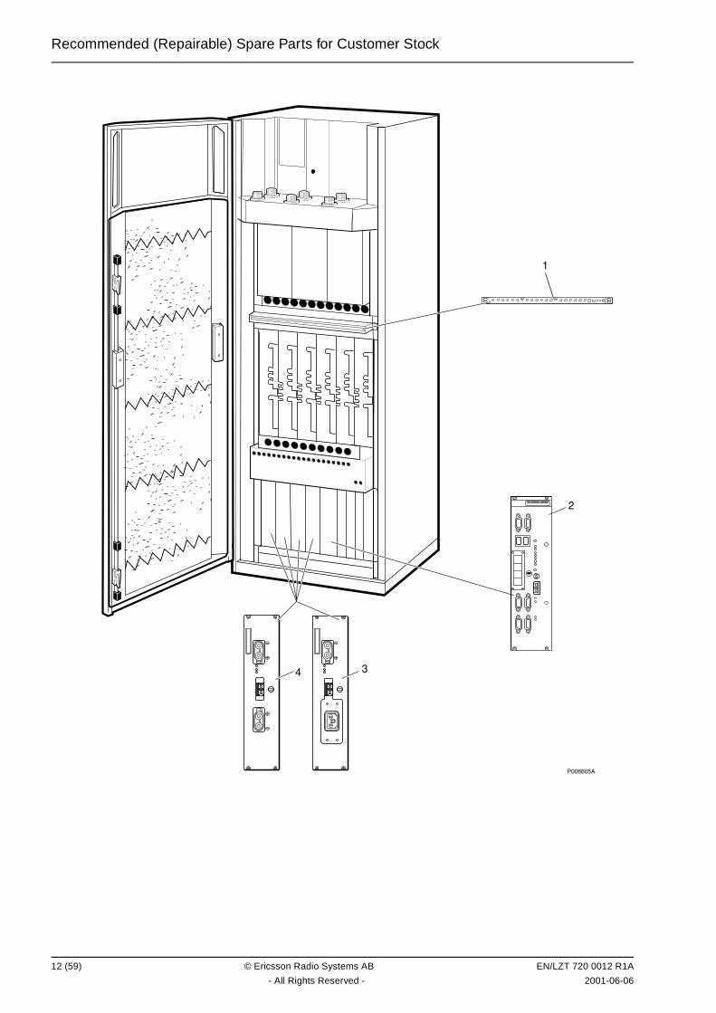
Recommended (Repairable) Spare Parts for Customer Stock
��������
� �
�
12 (59) © Ericsson Radio Systems AB EN/LZT 720 0012 R1A
- All Rights Reserved - 2001-06-06

Recommended (Repairable) Spare Parts for Customer Stock
����� 4����
��� ��� ��� &��" � ��� ��� &�� 0 ���������
1 KRY 101 1856/1 Unit CXU 900/1800MHz
2 BOE 602 14/1 Functional unit DXU-21
3 BML 231 202/1 Power supply unit PSU230 1000W +24VDC FC OPTO
4 BMR 960 014/1 Dc/dc-converter PSU48 1200W, -48/+24VDC FC
EN/LZT 720 0012 R1A © Ericsson Radio Systems AB 13 (59)
2001-06-06 - All Rights Reserved -
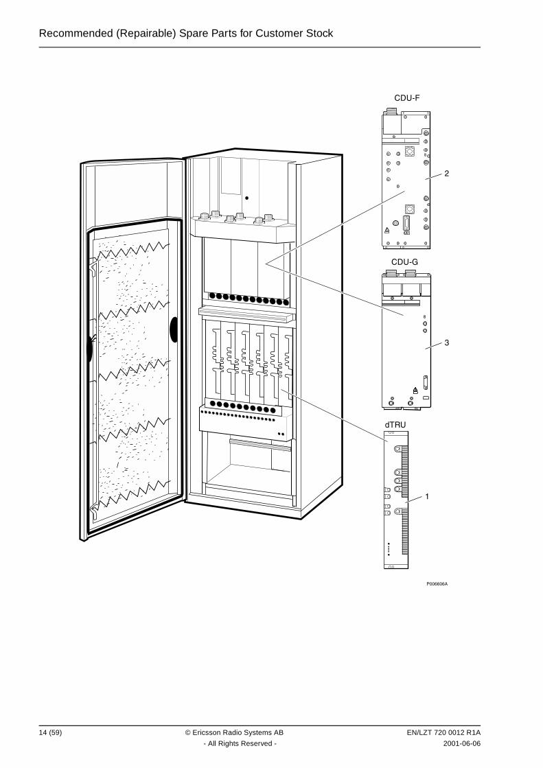
Recommended (Repairable) Spare Parts for Customer Stock
��������
��
�� ��
�� ��
�
�
14 (59) © Ericsson Radio Systems AB EN/LZT 720 0012 R1A
- All Rights Reserved - 2001-06-06
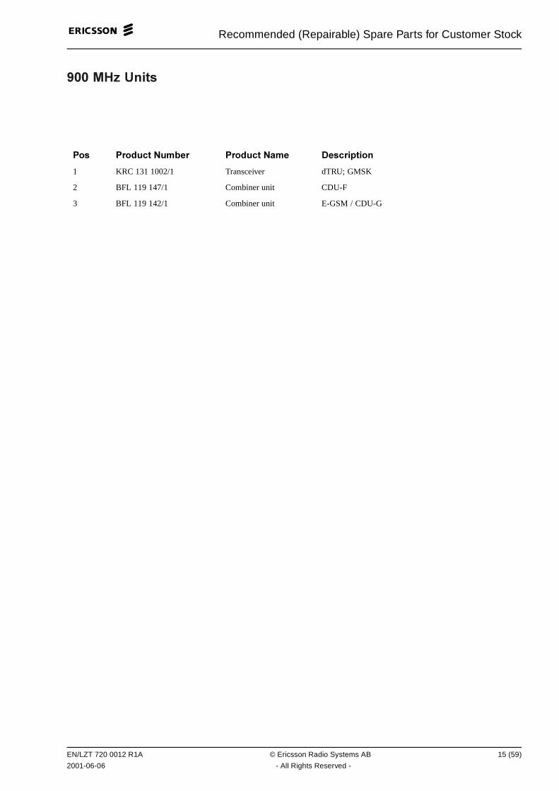
Recommended (Repairable) Spare Parts for Customer Stock
��� 25 4����
��� ��� ��� &��" � ��� ��� &�� 0 ���������
1 KRC 131 1002/1 Transceiver dTRU; GMSK
2 BFL 119 147/1 Combiner unit CDU-F
3 BFL 119 142/1 Combiner unit E-GSM / CDU-G
EN/LZT 720 0012 R1A © Ericsson Radio Systems AB 15 (59)
2001-06-06 - All Rights Reserved -
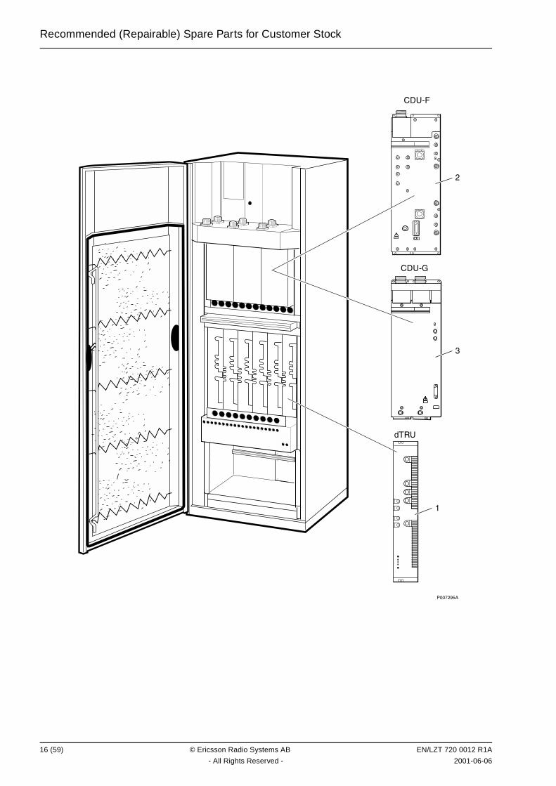
Recommended (Repairable) Spare Parts for Customer Stock
��������
��
�� ��
�� ��
�
�
16 (59) © Ericsson Radio Systems AB EN/LZT 720 0012 R1A
- All Rights Reserved - 2001-06-06

Recommended (Repairable) Spare Parts for Customer Stock
%6�� 25 4����
��� ��� ��� &��" � ��� ��� &�� 0 ���������
1 KRC 131 1003/1 Transceiver dTRU; GMSK
2 BFL 119 149/1 Combiner unit CDU-F
3 BFL 119 143/1 Combiner unit CDU-G
EN/LZT 720 0012 R1A © Ericsson Radio Systems AB 17 (59)
2001-06-06 - All Rights Reserved -
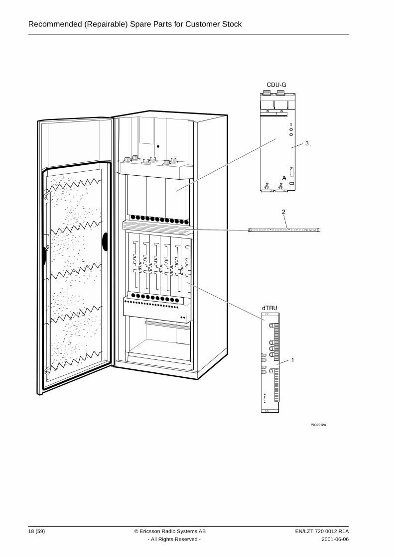
Recommended (Repairable) Spare Parts for Customer Stock
�� ��
�
�������
��
�
18 (59) © Ericsson Radio Systems AB EN/LZT 720 0012 R1A
- All Rights Reserved - 2001-06-06
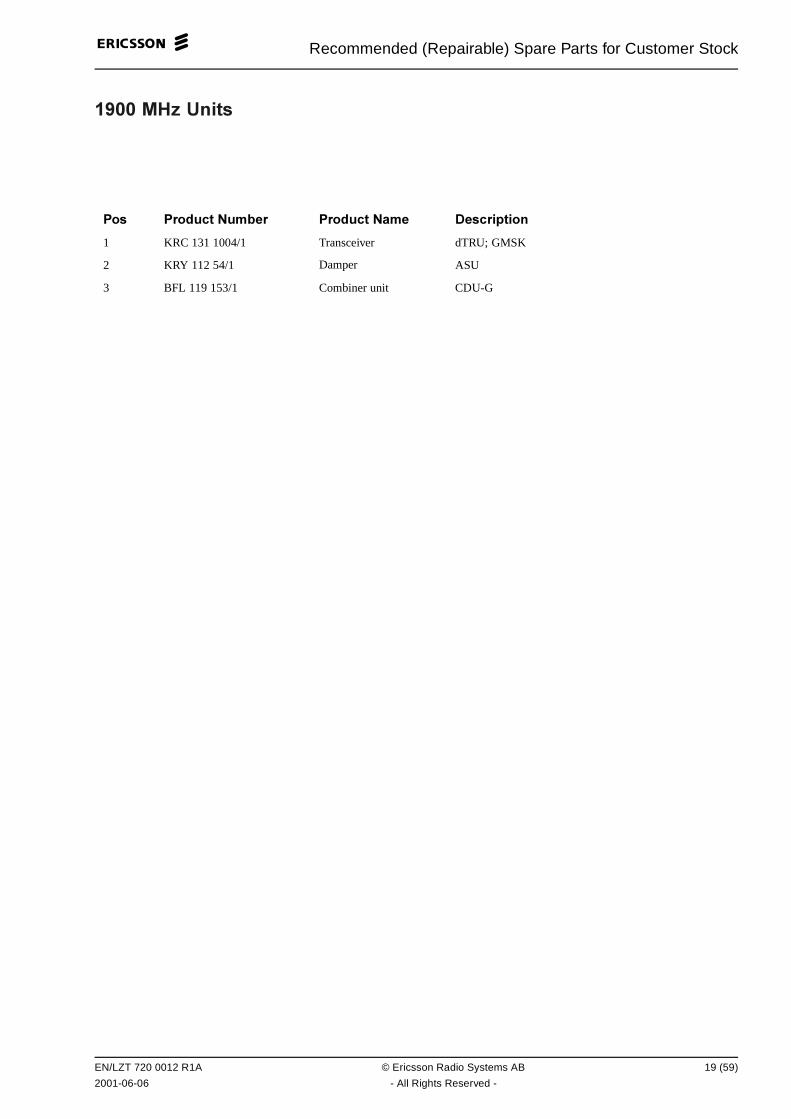
Recommended (Repairable) Spare Parts for Customer Stock
%��� 25 4����
��� ��� ��� &��" � ��� ��� &�� 0 ���������
1 KRC 131 1004/1 Transceiver dTRU; GMSK
2 KRY 112 54/1 Damper ASU
3 BFL 119 153/1 Combiner unit CDU-G
EN/LZT 720 0012 R1A © Ericsson Radio Systems AB 19 (59)
2001-06-06 - All Rights Reserved -
Recommended (Repairable) Spare Parts for Customer Stock
This page is intentionally left blank
20 (59) © Ericsson Radio Systems AB EN/LZT 720 0012 R1A
- All Rights Reserved - 2001-06-06
Recommended (Not Repairable) Spare Parts for Customer Stock
� ���� � !&�� � �����"� # ��� ����� ��������� � ���$
("��� ���� ����� �
All parts in this chapter have the internal code = R.
These parts are recommended for customer stock, and are intended to be replaced on site, or at a localshop and are intended to be disposed of after consumption.
EN/LZT 720 0012 R1A © Ericsson Radio Systems AB 21 (59)
2001-06-06 - All Rights Reserved -
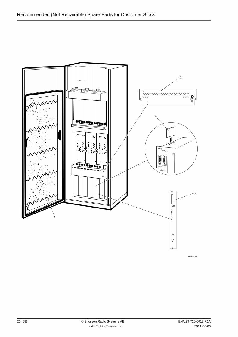
Recommended (Not Repairable) Spare Parts for Customer Stock
�����
���
����
���
����
��
����
��
����
��
����
��
���� ������ � �������
��������
�
�� �
�!��� � �
������ ������
���"��!#������
�$# �%&��'��
�
�
22 (59) © Ericsson Radio Systems AB EN/LZT 720 0012 R1A
- All Rights Reserved - 2001-06-06
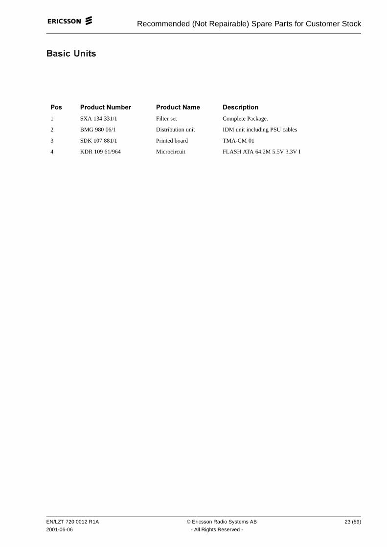
Recommended (Not Repairable) Spare Parts for Customer Stock
����� 4����
��� ��� ��� &��" � ��� ��� &�� 0 ���������
1 SXA 134 331/1 Filter set Complete Package.
2 BMG 980 06/1 Distribution unit IDM unit including PSU cables
3 SDK 107 881/1 Printed board TMA-CM 01
4 KDR 109 61/964 Microcircuit FLASH ATA 64.2M 5.5V 3.3V I
EN/LZT 720 0012 R1A © Ericsson Radio Systems AB 23 (59)
2001-06-06 - All Rights Reserved -
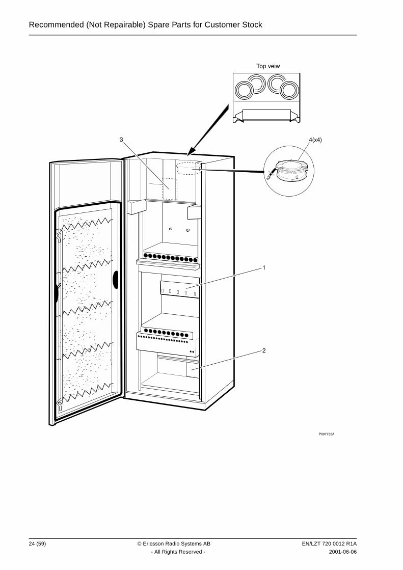
Recommended (Not Repairable) Spare Parts for Customer Stock
��������
�
� �����
��������
24 (59) © Ericsson Radio Systems AB EN/LZT 720 0012 R1A
- All Rights Reserved - 2001-06-06
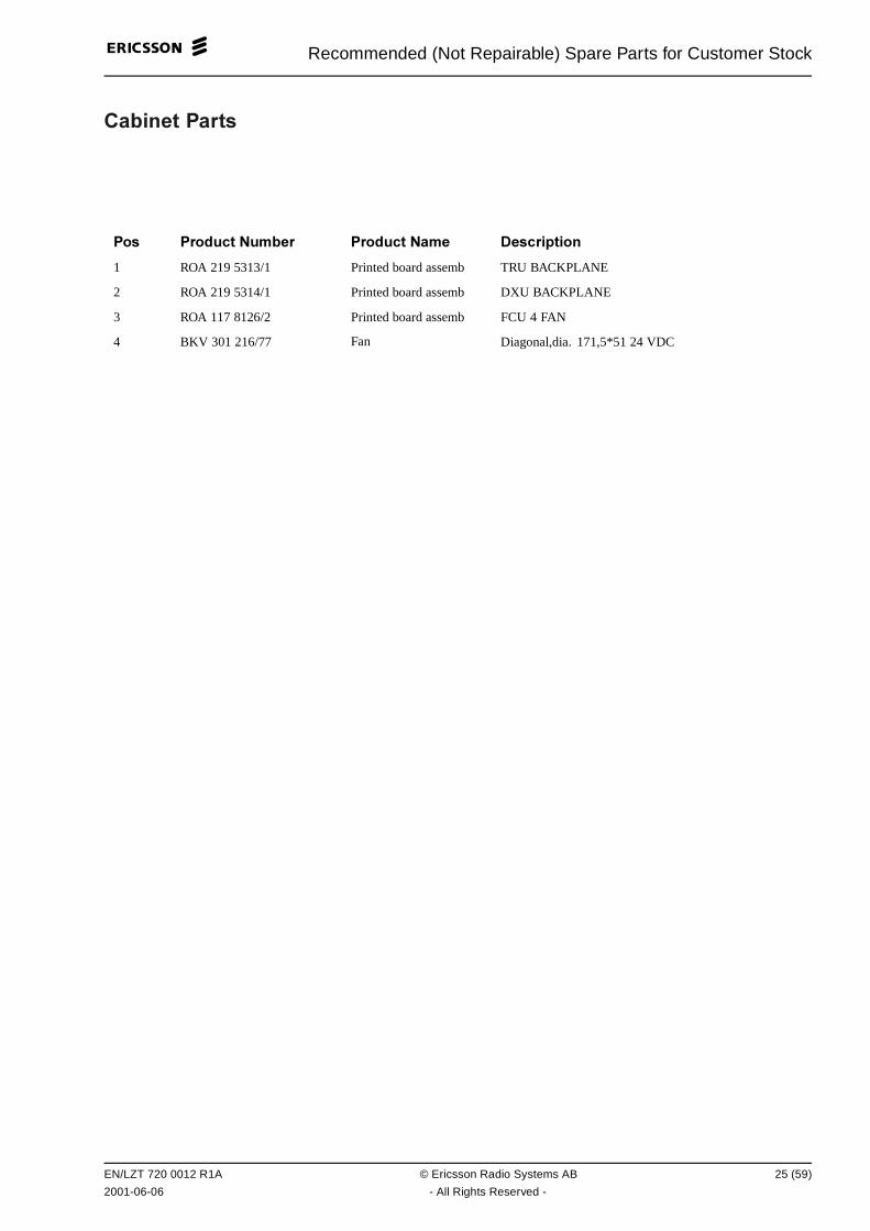
Recommended (Not Repairable) Spare Parts for Customer Stock
��"�� � �����
��� ��� ��� &��" � ��� ��� &�� 0 ���������
1 ROA 219 5313/1 Printed board assemb TRU BACKPLANE
2 ROA 219 5314/1 Printed board assemb DXU BACKPLANE
3 ROA 117 8126/2 Printed board assemb FCU 4 FAN
4 BKV 301 216/77 Fan Diagonal,dia. 171,5*51 24 VDC
EN/LZT 720 0012 R1A © Ericsson Radio Systems AB 25 (59)
2001-06-06 - All Rights Reserved -
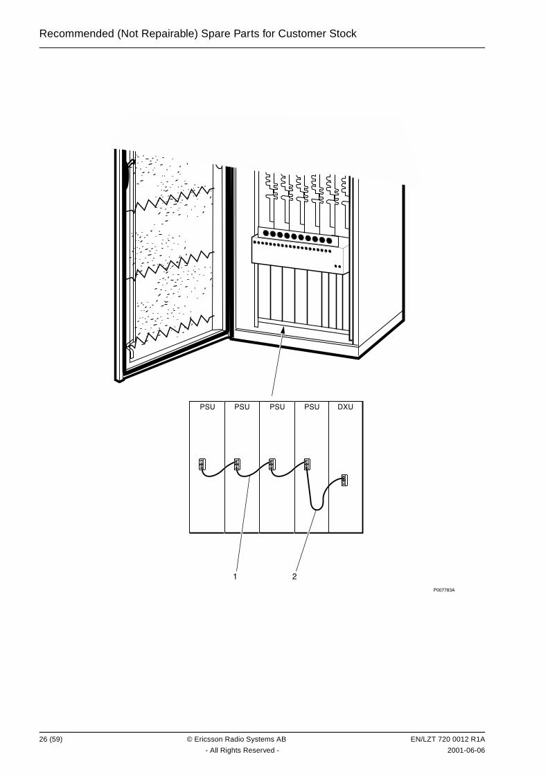
Recommended (Not Repairable) Spare Parts for Customer Stock
��������
� � � � �!
�
26 (59) © Ericsson Radio Systems AB EN/LZT 720 0012 R1A
- All Rights Reserved - 2001-06-06
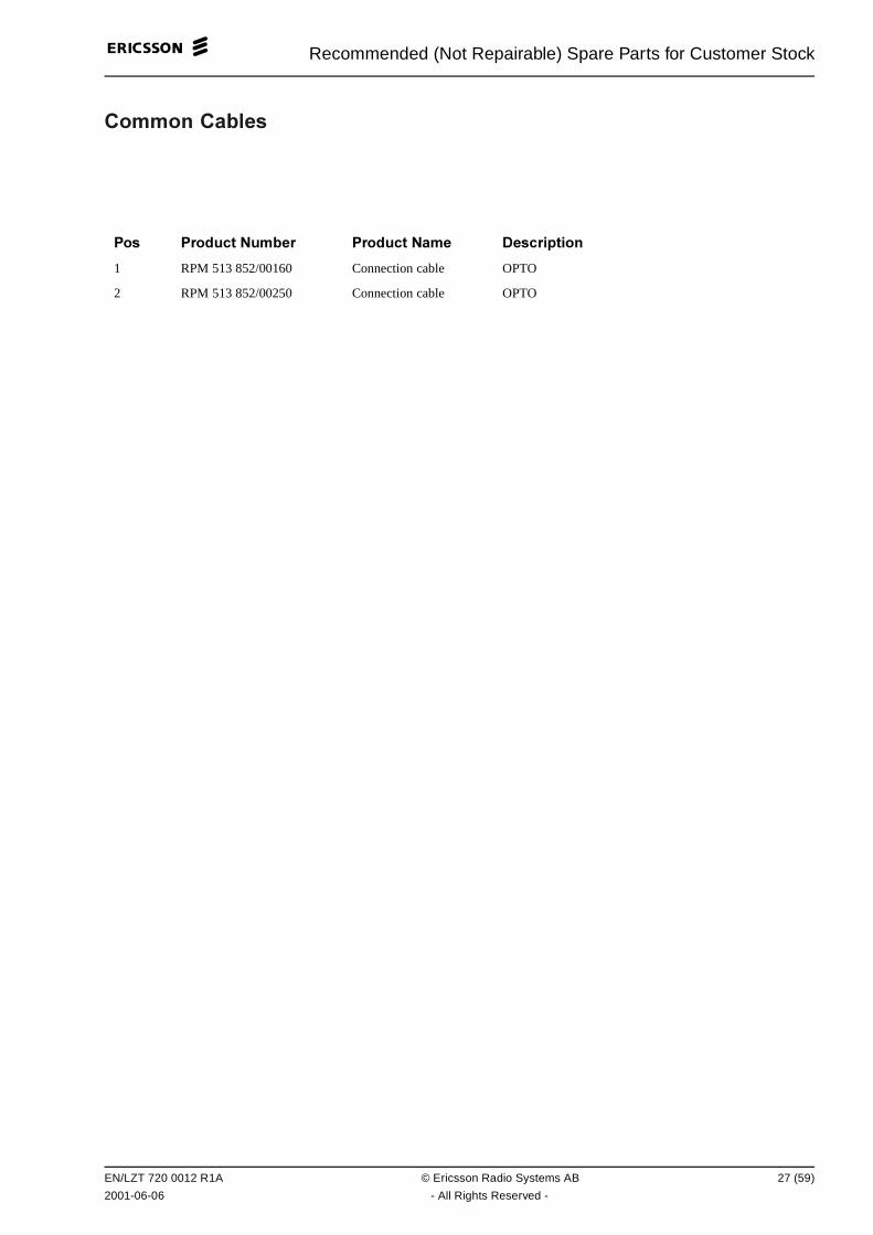
Recommended (Not Repairable) Spare Parts for Customer Stock
������ ��"� �
��� ��� ��� &��" � ��� ��� &�� 0 ���������
1 RPM 513 852/00160 Connection cable OPTO
2 RPM 513 852/00250 Connection cable OPTO
EN/LZT 720 0012 R1A © Ericsson Radio Systems AB 27 (59)
2001-06-06 - All Rights Reserved -
Recommended (Not Repairable) Spare Parts for Customer Stock
This page is intentionally left blank
28 (59) © Ericsson Radio Systems AB EN/LZT 720 0012 R1A
- All Rights Reserved - 2001-06-06
Other Available Parts
'�� � ()����"� �����
("��� ���� ����� �
All parts in this chapter have the internal code = A.
These parts are not recommended for customer stock. The parts are available upon request and thelead time may be longer.
EN/LZT 720 0012 R1A © Ericsson Radio Systems AB 29 (59)
2001-06-06 - All Rights Reserved -
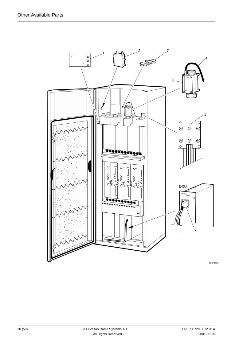
Other Available Parts
��������
�
�
�
���"��!#������
�
�!
�
�
30 (59) © Ericsson Radio Systems AB EN/LZT 720 0012 R1A
- All Rights Reserved - 2001-06-06
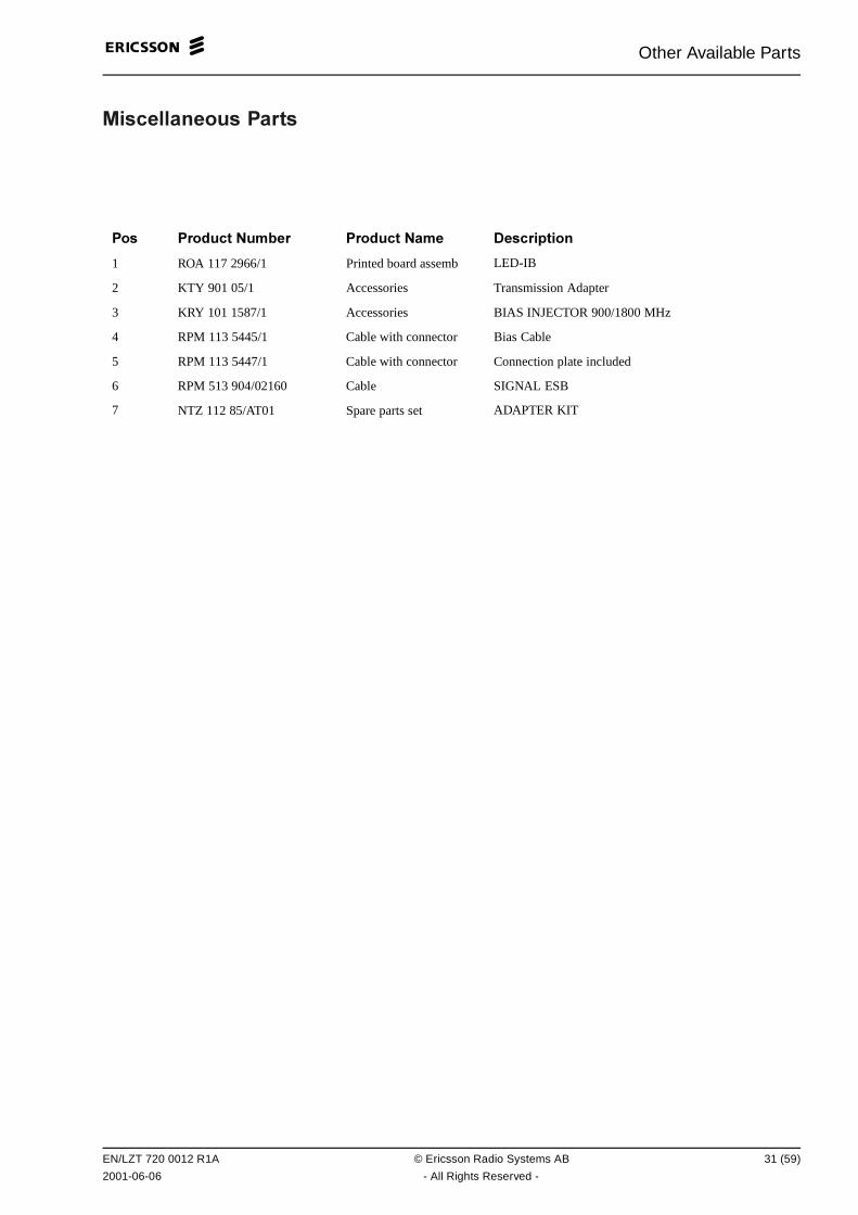
Other Available Parts
��� ���� ��� �����
��� ��� ��� &��" � ��� ��� &�� 0 ���������
1 ROA 117 2966/1 Printed board assemb LED-IB
2 KTY 901 05/1 Accessories Transmission Adapter
3 KRY 101 1587/1 Accessories BIAS INJECTOR 900/1800 MHz
4 RPM 113 5445/1 Cable with connector Bias Cable
5 RPM 113 5447/1 Cable with connector Connection plate included
6 RPM 513 904/02160 Cable SIGNAL ESB
7 NTZ 112 85/AT01 Spare parts set ADAPTER KIT
EN/LZT 720 0012 R1A © Ericsson Radio Systems AB 31 (59)
2001-06-06 - All Rights Reserved -
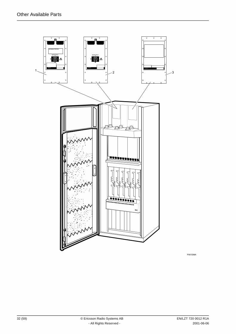
Other Available Parts
��������
(�)&*&+,�##-&#*�&
$�*&���(*�.
����"��
$�*&���(*�.
����"�����/� ����
�� �
32 (59) © Ericsson Radio Systems AB EN/LZT 720 0012 R1A
- All Rights Reserved - 2001-06-06
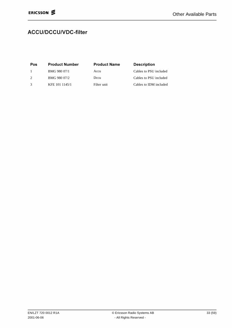
Other Available Parts
(��470��4780�9���� �
��� ��� ��� &��" � ��� ��� &�� 0 ���������
1 BMG 980 07/1 Accu Cables to PSU included
2 BMG 980 07/2 Dccu Cables to PSU included
3 KFE 101 1145/1 Filter unit Cables to IDM included
EN/LZT 720 0012 R1A © Ericsson Radio Systems AB 33 (59)
2001-06-06 - All Rights Reserved -

Other Available Parts
��������
�
�
�
�
�
�
�
34 (59) © Ericsson Radio Systems AB EN/LZT 720 0012 R1A
- All Rights Reserved - 2001-06-06
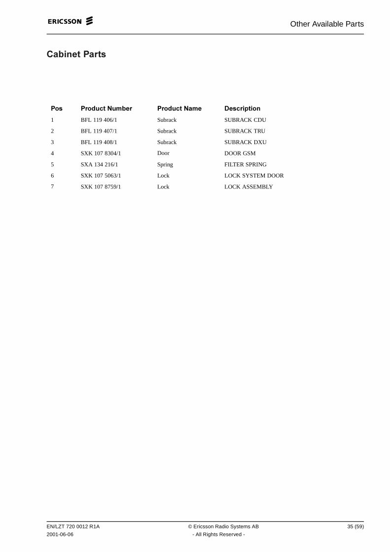
Other Available Parts
��"�� � �����
��� ��� ��� &��" � ��� ��� &�� 0 ���������
1 BFL 119 406/1 Subrack SUBRACK CDU
2 BFL 119 407/1 Subrack SUBRACK TRU
3 BFL 119 408/1 Subrack SUBRACK DXU
4 SXK 107 8304/1 Door DOOR GSM
5 SXA 134 216/1 Spring FILTER SPRING
6 SXK 107 5063/1 Lock LOCK SYSTEM DOOR
7 SXK 107 8759/1 Lock LOCK ASSEMBLY
EN/LZT 720 0012 R1A © Ericsson Radio Systems AB 35 (59)
2001-06-06 - All Rights Reserved -
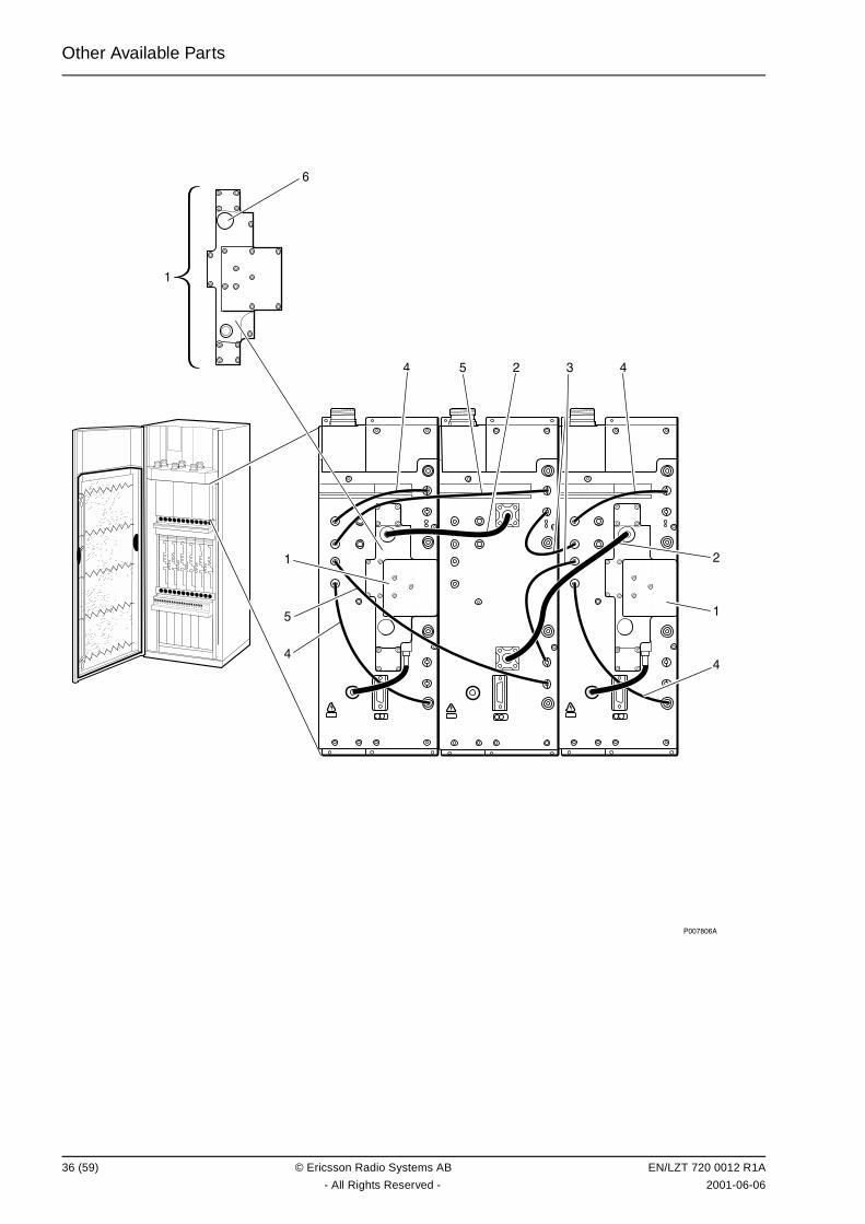
Other Available Parts
��������
� � � � �
�
�
�
�
�
36 (59) © Ericsson Radio Systems AB EN/LZT 720 0012 R1A
- All Rights Reserved - 2001-06-06
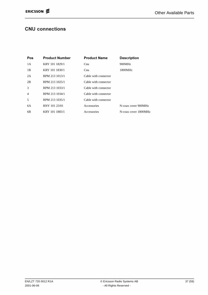
Other Available Parts
�&4 ���� ������
��� ��� ��� &��" � ��� ��� &�� 0 ���������
1A KRY 101 1829/1 Cnu 900MHz
1B KRY 101 1830/1 Cnu 1800MHz
2A RPM 213 1013/1 Cable with connector
2B RPM 213 1025/1 Cable with connector
3 RPM 213 1033/1 Cable with connector
4 RPM 213 1034/1 Cable with connector
5 RPM 213 1035/1 Cable with connector
6A RNY 101 23/01 Accessories N-coax cover 900MHz
6B KRY 101 1883/1 Accessories N-coax cover 1800MHz
EN/LZT 720 0012 R1A © Ericsson Radio Systems AB 37 (59)
2001-06-06 - All Rights Reserved -
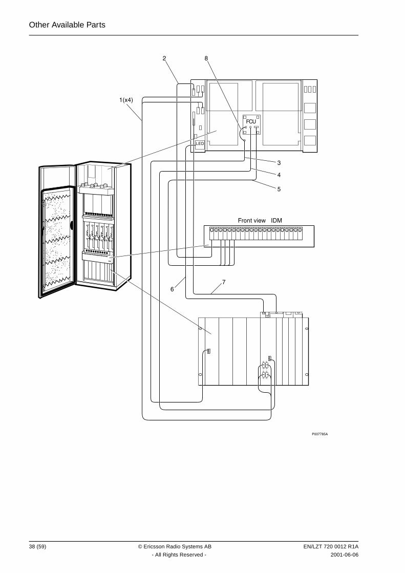
Other Available Parts
��������
��
"#�
�$�%&��������'�(
�
����
�
�
��
�
�
38 (59) © Ericsson Radio Systems AB EN/LZT 720 0012 R1A
- All Rights Reserved - 2001-06-06

Other Available Parts
��"� �
��� ��� ��� &��" � ��� ��� &�� 0 ���������
1 RPM 513 870/02250 Cable with connector 120 ohm/L=2.25 m/Bus G703/DXU11
2 RPM 513 1110/01700 Connection cable Connect.Cable +24V
3 RPM 513 1410/02500 Optical fibre cable OPTICAL FIBRE CABLE
4 RPM 513 1409/02500 Optical fibre cable OPTICAL FIBRE CABLE
5 RPM 513 1138/01700 Power cable POWER CABLE
6 RPM 513 1116/02500 Signalling cable LED-CABLE GSM SYST
7 RPM 513 1108/02660 Connection cable EXT-LARM GSM SYST
8 RPM 982 02/200 Opt.cable w. connect L=200 MM
EN/LZT 720 0012 R1A © Ericsson Radio Systems AB 39 (59)
2001-06-06 - All Rights Reserved -
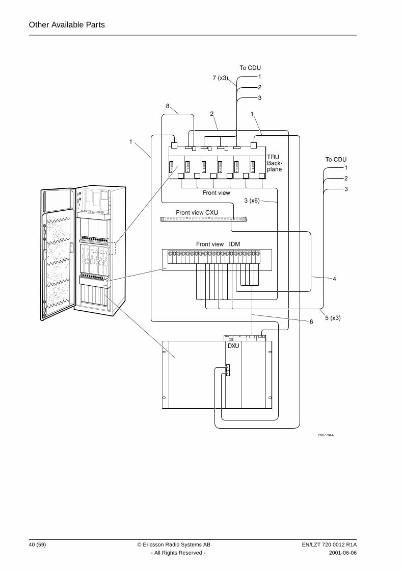
Other Available Parts
��������
�
������
�
�������$�%&�����
�� )*+,��-*%�
�$�%&��������'�(
�
�
������
�
�
�
�
�����
�����
�$�%&�������!
�!
40 (59) © Ericsson Radio Systems AB EN/LZT 720 0012 R1A
- All Rights Reserved - 2001-06-06
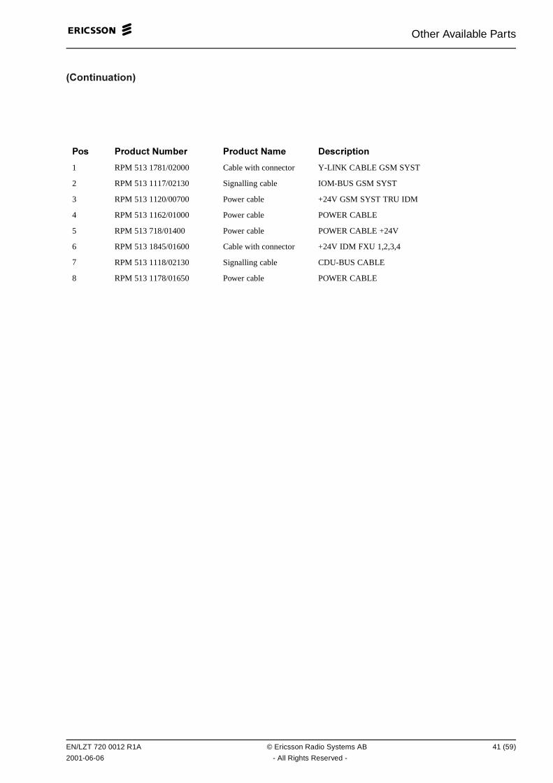
Other Available Parts
!������������#
��� ��� ��� &��" � ��� ��� &�� 0 ���������
1 RPM 513 1781/02000 Cable with connector Y-LINK CABLE GSM SYST
2 RPM 513 1117/02130 Signalling cable IOM-BUS GSM SYST
3 RPM 513 1120/00700 Power cable +24V GSM SYST TRU IDM
4 RPM 513 1162/01000 Power cable POWER CABLE
5 RPM 513 718/01400 Power cable POWER CABLE +24V
6 RPM 513 1845/01600 Cable with connector +24V IDM FXU 1,2,3,4
7 RPM 513 1118/02130 Signalling cable CDU-BUS CABLE
8 RPM 513 1178/01650 Power cable POWER CABLE
EN/LZT 720 0012 R1A © Ericsson Radio Systems AB 41 (59)
2001-06-06 - All Rights Reserved -
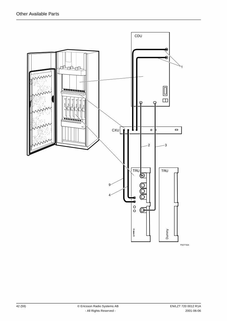
Other Available Parts
��������
�!
�� ��
��
�./
/0
�
��
�
42 (59) © Ericsson Radio Systems AB EN/LZT 720 0012 R1A
- All Rights Reserved - 2001-06-06
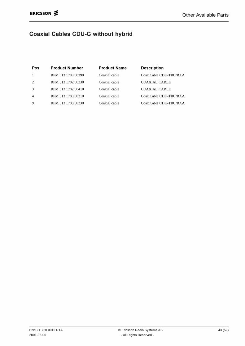
Other Available Parts
���/��� ��"� � �049� +������ ��"��
��� ��� ��� &��" � ��� ��� &�� 0 ���������
1 RPM 513 1783/00390 Coaxial cable Coax.Cable CDU-TRU/RXA
2 RPM 513 1782/00230 Coaxial cable COAXIAL CABLE
3 RPM 513 1782/00410 Coaxial cable COAXIAL CABLE
4 RPM 513 1783/00210 Coaxial cable Coax.Cable CDU-TRU/RXA
9 RPM 513 1783/00230 Coaxial cable Coax.Cable CDU-TRU/RXA
EN/LZT 720 0012 R1A © Ericsson Radio Systems AB 43 (59)
2001-06-06 - All Rights Reserved -
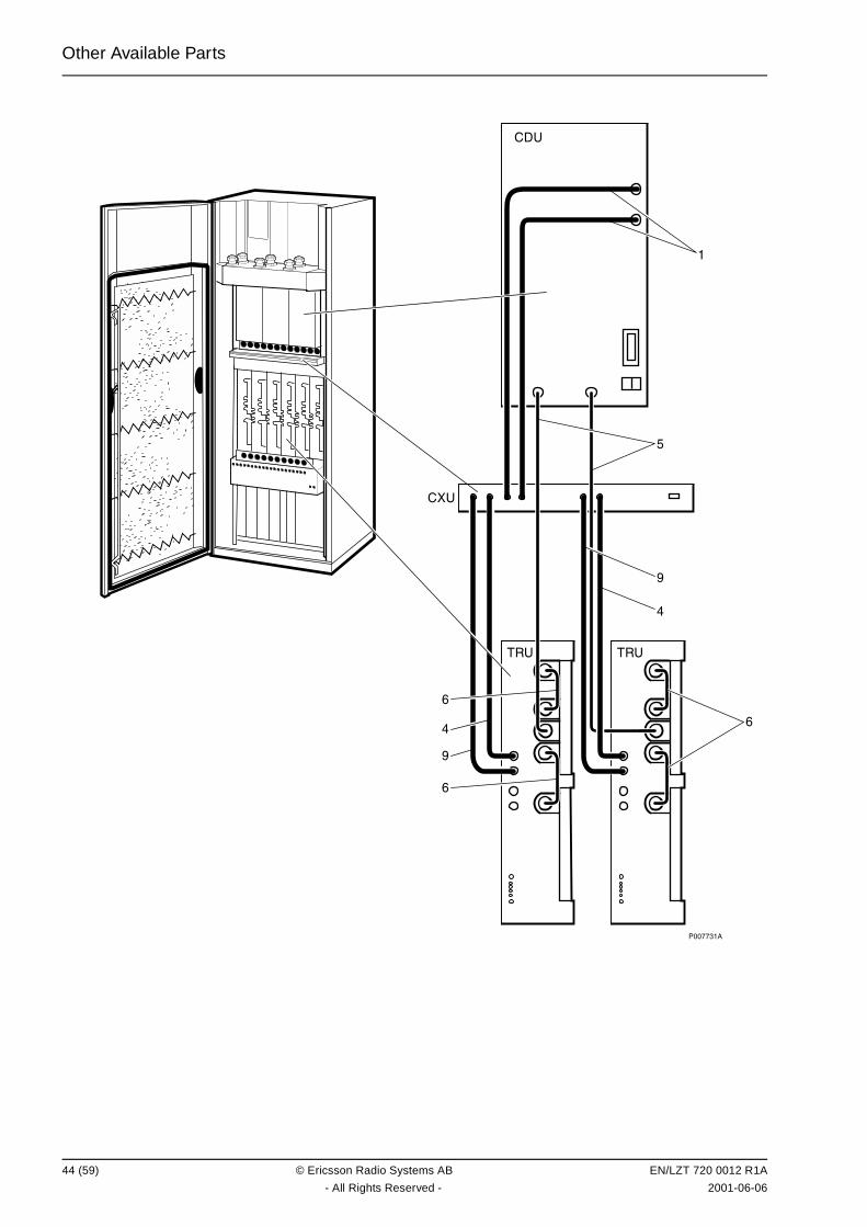
Other Available Parts
�������
�!
��
��
��
�
�
�
�
�
�
�
�
44 (59) © Ericsson Radio Systems AB EN/LZT 720 0012 R1A
- All Rights Reserved - 2001-06-06

Other Available Parts
���/��� ��"� � �049� +��� ��"��
��� ��� ��� &��" � ��� ��� &�� 0 ���������
1 RPM 513 1783/00390 Coaxial cable Coax.Cable CDU-TRU/RXA
4 RPM 513 1783/00210 Coaxial cable Coax.Cable CDU-TRU/RXA
5 RPM 513 1782/00310 Coaxial cable COAXIAL CABLE
6 RPM 513 1782/00070 Coaxial cable COAXIAL CABLE
9 RPM 513 1783/00230 Coaxial cable Coax.Cable CDU-TRU/RXA
EN/LZT 720 0012 R1A © Ericsson Radio Systems AB 45 (59)
2001-06-06 - All Rights Reserved -

Other Available Parts
��������
�!
��
��
��
�
�
�
�
�
�
�
�
46 (59) © Ericsson Radio Systems AB EN/LZT 720 0012 R1A
- All Rights Reserved - 2001-06-06
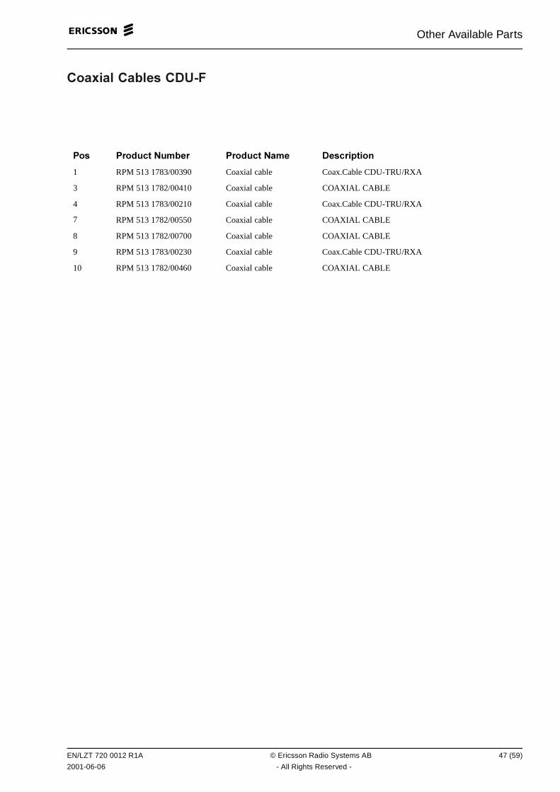
Other Available Parts
���/��� ��"� � �049:
��� ��� ��� &��" � ��� ��� &�� 0 ���������
1 RPM 513 1783/00390 Coaxial cable Coax.Cable CDU-TRU/RXA
3 RPM 513 1782/00410 Coaxial cable COAXIAL CABLE
4 RPM 513 1783/00210 Coaxial cable Coax.Cable CDU-TRU/RXA
7 RPM 513 1782/00550 Coaxial cable COAXIAL CABLE
8 RPM 513 1782/00700 Coaxial cable COAXIAL CABLE
9 RPM 513 1783/00230 Coaxial cable Coax.Cable CDU-TRU/RXA
10 RPM 513 1782/00460 Coaxial cable COAXIAL CABLE
EN/LZT 720 0012 R1A © Ericsson Radio Systems AB 47 (59)
2001-06-06 - All Rights Reserved -
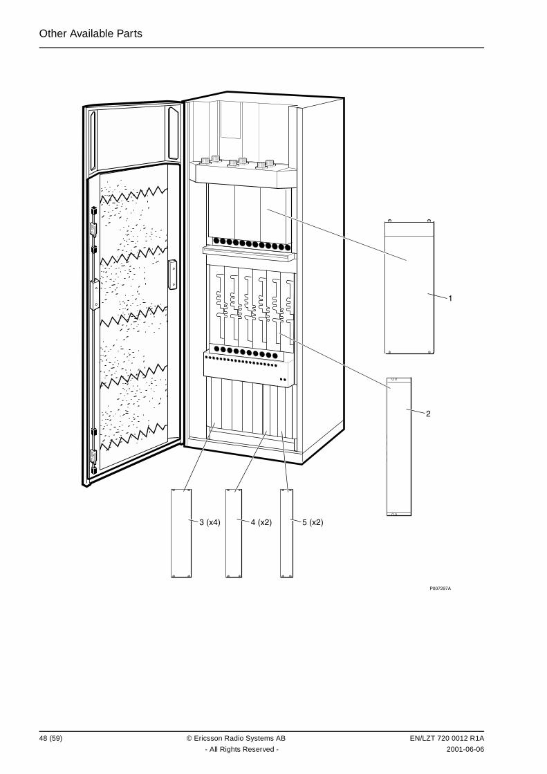
Other Available Parts
��������
�
������������������
48 (59) © Ericsson Radio Systems AB EN/LZT 720 0012 R1A
- All Rights Reserved - 2001-06-06
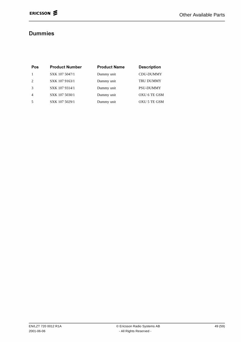
Other Available Parts
0���� �
��� ��� ��� &��" � ��� ��� &�� 0 ���������
1 SXK 107 5047/1 Dummy unit CDU-DUMMY
2 SXK 107 9163/1 Dummy unit TRU DUMMY
3 SXK 107 9314/1 Dummy unit PSU-DUMMY
4 SXK 107 5030/1 Dummy unit OXU 6 TE GSM
5 SXK 107 5029/1 Dummy unit OXU 5 TE GSM
EN/LZT 720 0012 R1A © Ericsson Radio Systems AB 49 (59)
2001-06-06 - All Rights Reserved -
Other Available Parts
This page is intentionally left blank
50 (59) © Ericsson Radio Systems AB EN/LZT 720 0012 R1A
- All Rights Reserved - 2001-06-06
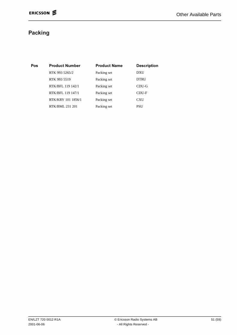
Other Available Parts
���$���
��� ��� ��� &��" � ��� ��� &�� 0 ���������
RTK 993 5265/2 Packing set DXU
RTK 993 5519 Packing set DTRU
RTK/BFL 119 142/1 Packing set CDU-G
RTK/BFL 119 147/1 Packing set CDU-F
RTK/KRY 101 1856/1 Packing set CXU
RTK/BML 231 201 Packing set PSU
EN/LZT 720 0012 R1A © Ericsson Radio Systems AB 51 (59)
2001-06-06 - All Rights Reserved -

Other Available Parts
This page is intentionally left blank
52 (59) © Ericsson Radio Systems AB EN/LZT 720 0012 R1A
- All Rights Reserved - 2001-06-06
Replaced and Withdrawn Parts
� ���� �� *��� ��+� �����
("��� ���� ����� �
This chapter shows replaced or withdrawn products
Due to continous improvement in design and production methods, some parts are changed.
This is the only place in this catalogue release where you still can find Product Numbers shown inprevious catalogues. In this way we manage to keep the Numerical Index as a list of orderable SpareParts.
EN/LZT 720 0012 R1A © Ericsson Radio Systems AB 53 (59)
2001-06-06 - All Rights Reserved -

Replaced and Withdrawn Parts
This page is intentionally left blank
54 (59) © Ericsson Radio Systems AB EN/LZT 720 0012 R1A
- All Rights Reserved - 2001-06-06
Replaced and Withdrawn Parts
��� ����� ������ !"��� #�� �����
EN/LZT 720 0012 R1A © Ericsson Radio Systems AB 55 (59)
2001-06-06 - All Rights Reserved -
Replaced and Withdrawn Parts
This page is intentionally left blank
56 (59) © Ericsson Radio Systems AB EN/LZT 720 0012 R1A
- All Rights Reserved - 2001-06-06
Numerical Index
&�� ����� .� /BFL 119 142/1 . . . . . . . . . . . . . . . . . . . . . . . . . . . . . . . . . . . . . . . . . . . . . . . . . . . . . . 15
BFL 119 143/1 . . . . . . . . . . . . . . . . . . . . . . . . . . . . . . . . . . . . . . . . . . . . . . . . . . . . . . 17
BFL 119 147/1 . . . . . . . . . . . . . . . . . . . . . . . . . . . . . . . . . . . . . . . . . . . . . . . . . . . . . . 15
BFL 119 149/1 . . . . . . . . . . . . . . . . . . . . . . . . . . . . . . . . . . . . . . . . . . . . . . . . . . . . . . 17
BFL 119 153/1 . . . . . . . . . . . . . . . . . . . . . . . . . . . . . . . . . . . . . . . . . . . . . . . . . . . . . . 19
BFL 119 406/1 . . . . . . . . . . . . . . . . . . . . . . . . . . . . . . . . . . . . . . . . . . . . . . . . . . . . . . 35
BFL 119 407/1 . . . . . . . . . . . . . . . . . . . . . . . . . . . . . . . . . . . . . . . . . . . . . . . . . . . . . . 35
BFL 119 408/1 . . . . . . . . . . . . . . . . . . . . . . . . . . . . . . . . . . . . . . . . . . . . . . . . . . . . . . 35
BKV 301 216/77 . . . . . . . . . . . . . . . . . . . . . . . . . . . . . . . . . . . . . . . . . . . . . . . . . . . . 25
BMG 980 06/1 . . . . . . . . . . . . . . . . . . . . . . . . . . . . . . . . . . . . . . . . . . . . . . . . . . . . . . 23
BMG 980 07/1 . . . . . . . . . . . . . . . . . . . . . . . . . . . . . . . . . . . . . . . . . . . . . . . . . . . . . . 33
BMG 980 07/2 . . . . . . . . . . . . . . . . . . . . . . . . . . . . . . . . . . . . . . . . . . . . . . . . . . . . . . 33
BML 231 202/1 . . . . . . . . . . . . . . . . . . . . . . . . . . . . . . . . . . . . . . . . . . . . . . . . . . . . . . 13
BMR 960 014/1 . . . . . . . . . . . . . . . . . . . . . . . . . . . . . . . . . . . . . . . . . . . . . . . . . . . . . . 13
BOE 602 14/1 . . . . . . . . . . . . . . . . . . . . . . . . . . . . . . . . . . . . . . . . . . . . . . . . . . . . . . . 13
KDR 109 61/964 . . . . . . . . . . . . . . . . . . . . . . . . . . . . . . . . . . . . . . . . . . . . . . . . . . . . 23
KFE 101 1145/1. . . . . . . . . . . . . . . . . . . . . . . . . . . . . . . . . . . . . . . . . . . . . . . . . . . . . 33
KRC 131 1002/1 . . . . . . . . . . . . . . . . . . . . . . . . . . . . . . . . . . . . . . . . . . . . . . . . . . . . 15
KRC 131 1003/1 . . . . . . . . . . . . . . . . . . . . . . . . . . . . . . . . . . . . . . . . . . . . . . . . . . . . 17
KRC 131 1004/1 . . . . . . . . . . . . . . . . . . . . . . . . . . . . . . . . . . . . . . . . . . . . . . . . . . . . 19
KRY 101 1587/1 . . . . . . . . . . . . . . . . . . . . . . . . . . . . . . . . . . . . . . . . . . . . . . . . . . . . 31
KRY 101 1829/1 . . . . . . . . . . . . . . . . . . . . . . . . . . . . . . . . . . . . . . . . . . . . . . . . . . . . 37
KRY 101 1830/1 . . . . . . . . . . . . . . . . . . . . . . . . . . . . . . . . . . . . . . . . . . . . . . . . . . . . 37
KRY 101 1856/1 . . . . . . . . . . . . . . . . . . . . . . . . . . . . . . . . . . . . . . . . . . . . . . . . . . . . 13
KRY 101 1883/1 . . . . . . . . . . . . . . . . . . . . . . . . . . . . . . . . . . . . . . . . . . . . . . . . . . . . 37
KRY 112 54/1 . . . . . . . . . . . . . . . . . . . . . . . . . . . . . . . . . . . . . . . . . . . . . . . . . . . . . . . 19
KTY 901 05/1 . . . . . . . . . . . . . . . . . . . . . . . . . . . . . . . . . . . . . . . . . . . . . . . . . . . . . . . 31
NTZ 112 85/AT01. . . . . . . . . . . . . . . . . . . . . . . . . . . . . . . . . . . . . . . . . . . . . . . . . . . . . 31
RNY 101 23/01 . . . . . . . . . . . . . . . . . . . . . . . . . . . . . . . . . . . . . . . . . . . . . . . . . . . . . . 37
ROA 117 2966/1 . . . . . . . . . . . . . . . . . . . . . . . . . . . . . . . . . . . . . . . . . . . . . . . . . . . . 31
ROA 117 8126/2 . . . . . . . . . . . . . . . . . . . . . . . . . . . . . . . . . . . . . . . . . . . . . . . . . . . . 25
ROA 219 5313/1 . . . . . . . . . . . . . . . . . . . . . . . . . . . . . . . . . . . . . . . . . . . . . . . . . . . . 25
ROA 219 5314/1 . . . . . . . . . . . . . . . . . . . . . . . . . . . . . . . . . . . . . . . . . . . . . . . . . . . . 25
RPM 113 5445/1 . . . . . . . . . . . . . . . . . . . . . . . . . . . . . . . . . . . . . . . . . . . . . . . . . . . . 31
RPM 113 5447/1 . . . . . . . . . . . . . . . . . . . . . . . . . . . . . . . . . . . . . . . . . . . . . . . . . . . . 31
RPM 213 1013/1 . . . . . . . . . . . . . . . . . . . . . . . . . . . . . . . . . . . . . . . . . . . . . . . . . . . . 37
RPM 213 1025/1 . . . . . . . . . . . . . . . . . . . . . . . . . . . . . . . . . . . . . . . . . . . . . . . . . . . . 37
RPM 213 1033/1 . . . . . . . . . . . . . . . . . . . . . . . . . . . . . . . . . . . . . . . . . . . . . . . . . . . . 37
RPM 213 1034/1 . . . . . . . . . . . . . . . . . . . . . . . . . . . . . . . . . . . . . . . . . . . . . . . . . . . . 37
RPM 213 1035/1 . . . . . . . . . . . . . . . . . . . . . . . . . . . . . . . . . . . . . . . . . . . . . . . . . . . . 37
EN/LZT 720 0012 R1A © Ericsson Radio Systems AB 57 (59)
2001-06-06 - All Rights Reserved -

Numerical Index
RPM 513 1108/02660 . . . . . . . . . . . . . . . . . . . . . . . . . . . . . . . . . . . . . . . . . . . . . . . . . . . 39
RPM 513 1110/01700 . . . . . . . . . . . . . . . . . . . . . . . . . . . . . . . . . . . . . . . . . . . . . . . . . . . 39
RPM 513 1116/02500 . . . . . . . . . . . . . . . . . . . . . . . . . . . . . . . . . . . . . . . . . . . . . . . . . . . 39
RPM 513 1117/02130 . . . . . . . . . . . . . . . . . . . . . . . . . . . . . . . . . . . . . . . . . . . . . . . . . . . 41
RPM 513 1118/02130 . . . . . . . . . . . . . . . . . . . . . . . . . . . . . . . . . . . . . . . . . . . . . . . . . . . 41
RPM 513 1120/00700 . . . . . . . . . . . . . . . . . . . . . . . . . . . . . . . . . . . . . . . . . . . . . . . . . . . 41
RPM 513 1138/01700 . . . . . . . . . . . . . . . . . . . . . . . . . . . . . . . . . . . . . . . . . . . . . . . . . . . 39
RPM 513 1162/01000 . . . . . . . . . . . . . . . . . . . . . . . . . . . . . . . . . . . . . . . . . . . . . . . . . . . 41
RPM 513 1178/01650 . . . . . . . . . . . . . . . . . . . . . . . . . . . . . . . . . . . . . . . . . . . . . . . . . . . 41
RPM 513 1409/02500 . . . . . . . . . . . . . . . . . . . . . . . . . . . . . . . . . . . . . . . . . . . . . . . . . . . 39
RPM 513 1410/02500 . . . . . . . . . . . . . . . . . . . . . . . . . . . . . . . . . . . . . . . . . . . . . . . . . . . 39
RPM 513 1781/02000 . . . . . . . . . . . . . . . . . . . . . . . . . . . . . . . . . . . . . . . . . . . . . . . . . . . 41
RPM 513 1782/00070 . . . . . . . . . . . . . . . . . . . . . . . . . . . . . . . . . . . . . . . . . . . . . . . . . . . 45
RPM 513 1782/00230 . . . . . . . . . . . . . . . . . . . . . . . . . . . . . . . . . . . . . . . . . . . . . . . . . . . 43
RPM 513 1782/00310 . . . . . . . . . . . . . . . . . . . . . . . . . . . . . . . . . . . . . . . . . . . . . . . . . . . 45
RPM 513 1782/00410 . . . . . . . . . . . . . . . . . . . . . . . . . . . . . . . . . . . . . . . . . . . . . . . . . . . 43
RPM 513 1782/00410 . . . . . . . . . . . . . . . . . . . . . . . . . . . . . . . . . . . . . . . . . . . . . . . . . . . 47
RPM 513 1782/00460 . . . . . . . . . . . . . . . . . . . . . . . . . . . . . . . . . . . . . . . . . . . . . . . . . . . 47
RPM 513 1782/00550 . . . . . . . . . . . . . . . . . . . . . . . . . . . . . . . . . . . . . . . . . . . . . . . . . . . 47
RPM 513 1782/00700 . . . . . . . . . . . . . . . . . . . . . . . . . . . . . . . . . . . . . . . . . . . . . . . . . . . 47
RPM 513 1783/00210 . . . . . . . . . . . . . . . . . . . . . . . . . . . . . . . . . . . . . . . . . . . . . . . . . . . 45
RPM 513 1783/00210 . . . . . . . . . . . . . . . . . . . . . . . . . . . . . . . . . . . . . . . . . . . . . . . . . . . 43
RPM 513 1783/00210 . . . . . . . . . . . . . . . . . . . . . . . . . . . . . . . . . . . . . . . . . . . . . . . . . . . 47
RPM 513 1783/00230 . . . . . . . . . . . . . . . . . . . . . . . . . . . . . . . . . . . . . . . . . . . . . . . . . . . 45
RPM 513 1783/00230 . . . . . . . . . . . . . . . . . . . . . . . . . . . . . . . . . . . . . . . . . . . . . . . . . . . 47
RPM 513 1783/00230 . . . . . . . . . . . . . . . . . . . . . . . . . . . . . . . . . . . . . . . . . . . . . . . . . . . 43
RPM 513 1783/00390 . . . . . . . . . . . . . . . . . . . . . . . . . . . . . . . . . . . . . . . . . . . . . . . . . . . 43
RPM 513 1783/00390 . . . . . . . . . . . . . . . . . . . . . . . . . . . . . . . . . . . . . . . . . . . . . . . . . . . 45
RPM 513 1783/00390 . . . . . . . . . . . . . . . . . . . . . . . . . . . . . . . . . . . . . . . . . . . . . . . . . . . 47
RPM 513 1845/01600 . . . . . . . . . . . . . . . . . . . . . . . . . . . . . . . . . . . . . . . . . . . . . . . . . . . 41
RPM 513 718/01400 . . . . . . . . . . . . . . . . . . . . . . . . . . . . . . . . . . . . . . . . . . . . . . . . . . 41
RPM 513 852/00160 . . . . . . . . . . . . . . . . . . . . . . . . . . . . . . . . . . . . . . . . . . . . . . . . . . 27
RPM 513 852/00250 . . . . . . . . . . . . . . . . . . . . . . . . . . . . . . . . . . . . . . . . . . . . . . . . . . 27
RPM 513 870/02250 . . . . . . . . . . . . . . . . . . . . . . . . . . . . . . . . . . . . . . . . . . . . . . . . . . 39
RPM 513 904/02160 . . . . . . . . . . . . . . . . . . . . . . . . . . . . . . . . . . . . . . . . . . . . . . . . . . 31
RPM 982 02/200 . . . . . . . . . . . . . . . . . . . . . . . . . . . . . . . . . . . . . . . . . . . . . . . . . . . . 39
RTK 993 5265/2. . . . . . . . . . . . . . . . . . . . . . . . . . . . . . . . . . . . . . . . . . . . . . . . . . . . . 51
RTK 993 5519. . . . . . . . . . . . . . . . . . . . . . . . . . . . . . . . . . . . . . . . . . . . . . . . . . . . . . . 51
RTK/BFL 119 142/1 . . . . . . . . . . . . . . . . . . . . . . . . . . . . . . . . . . . . . . . . . . . . . . . . . . 51
58 (59) © Ericsson Radio Systems AB EN/LZT 720 0012 R1A
- All Rights Reserved - 2001-06-06
Numerical Index
RTK/BFL 119 147/1 . . . . . . . . . . . . . . . . . . . . . . . . . . . . . . . . . . . . . . . . . . . . . . . . . . 51
RTK/BML 231 201 . . . . . . . . . . . . . . . . . . . . . . . . . . . . . . . . . . . . . . . . . . . . . . . . . . . . 51
RTK/KRY 101 1856/1 . . . . . . . . . . . . . . . . . . . . . . . . . . . . . . . . . . . . . . . . . . . . . . . . . . 51
SDK 107 881/1 . . . . . . . . . . . . . . . . . . . . . . . . . . . . . . . . . . . . . . . . . . . . . . . . . . . . . . 23
SXA 134 216/1 . . . . . . . . . . . . . . . . . . . . . . . . . . . . . . . . . . . . . . . . . . . . . . . . . . . . . . 35
SXA 134 331/1 . . . . . . . . . . . . . . . . . . . . . . . . . . . . . . . . . . . . . . . . . . . . . . . . . . . . . . 23
SXK 107 5029/1 . . . . . . . . . . . . . . . . . . . . . . . . . . . . . . . . . . . . . . . . . . . . . . . . . . . . 49
SXK 107 5030/1 . . . . . . . . . . . . . . . . . . . . . . . . . . . . . . . . . . . . . . . . . . . . . . . . . . . . 49
SXK 107 5047/1 . . . . . . . . . . . . . . . . . . . . . . . . . . . . . . . . . . . . . . . . . . . . . . . . . . . . 49
SXK 107 5063/1 . . . . . . . . . . . . . . . . . . . . . . . . . . . . . . . . . . . . . . . . . . . . . . . . . . . . 35
SXK 107 8304/1 . . . . . . . . . . . . . . . . . . . . . . . . . . . . . . . . . . . . . . . . . . . . . . . . . . . . 35
SXK 107 8759/1 . . . . . . . . . . . . . . . . . . . . . . . . . . . . . . . . . . . . . . . . . . . . . . . . . . . . 35
SXK 107 9163/1 . . . . . . . . . . . . . . . . . . . . . . . . . . . . . . . . . . . . . . . . . . . . . . . . . . . . 49
SXK 107 9314/1 . . . . . . . . . . . . . . . . . . . . . . . . . . . . . . . . . . . . . . . . . . . . . . . . . . . . 49
EN/LZT 720 0012 R1A © Ericsson Radio Systems AB 59 (59)
2001-06-06 - All Rights Reserved -

.


