1 RC RC - - 11 11 NIR MEASUREMENTS. Principles and practices of NIR MEASUREMENTS. Principles and practices of EMF characterization and measurements EMF characterization and measurements V. Cruz V. Cruz Ornetta Ornetta , , National Engineering University National Engineering University - - National Institute for Research and Training in National Institute for Research and Training in Telecommunications (INICTEL Telecommunications (INICTEL - - UNI), Lima, Peru UNI), Lima, Peru IRPA 12 12th International Congress of the International Radiation Protection Association 19th-24th October 2008, Buenos Aires, Argentina
Transcript
1
RCRC--11 11 NIR MEASUREMENTS. Principles and practices of NIR MEASUREMENTS. Principles and practices of
EMF characterization and measurementsEMF characterization and measurements
V. Cruz V. Cruz OrnettaOrnetta, , National Engineering UniversityNational Engineering University--National Institute for Research and Training in National Institute for Research and Training in
Telecommunications (INICTELTelecommunications (INICTEL-- UNI), Lima, PeruUNI), Lima, Peru
IRPA 1212th International Congress of the International Radiation
Protection Association19th-24th October 2008, Buenos Aires, Argentina
2
SummarySummary
1. 1. IntroductionIntroduction
2. Standards for limiting exposure to electromagnetic fields2. Standards for limiting exposure to electromagnetic fields
3. Prediction of electromagnetic field near telecommunication st3. Prediction of electromagnetic field near telecommunication stations ations 3. 3. FieldField regionsregions
The concern about nonThe concern about non--ionizing radiation (NIR) and its study started in the 1950ionizing radiation (NIR) and its study started in the 1950’’s. It s. It was established a very comprehensive research that continues untwas established a very comprehensive research that continues until now. According to il now. According to the WHOthe WHO-- EMFEMF--Project database there are more than 3000 studies.Project database there are more than 3000 studies.
Within the frame of the WHO International EMF Project it have beWithin the frame of the WHO International EMF Project it have been developed a huge en developed a huge research effort in order to conduct the risk assessment of nonresearch effort in order to conduct the risk assessment of non--ionizing radiation as a ionizing radiation as a basic step to establish policies and actions to enhance levels obasic step to establish policies and actions to enhance levels of peoplef people’’s radio s radio protection.protection.
One important task to the risk assessment is the evaluation of eOne important task to the risk assessment is the evaluation of exposure levels coming xposure levels coming from diverse sources from NIR. This is why this short course is from diverse sources from NIR. This is why this short course is aimed to give the basic aimed to give the basic Principles and practices of EMF measurement.Principles and practices of EMF measurement.
4
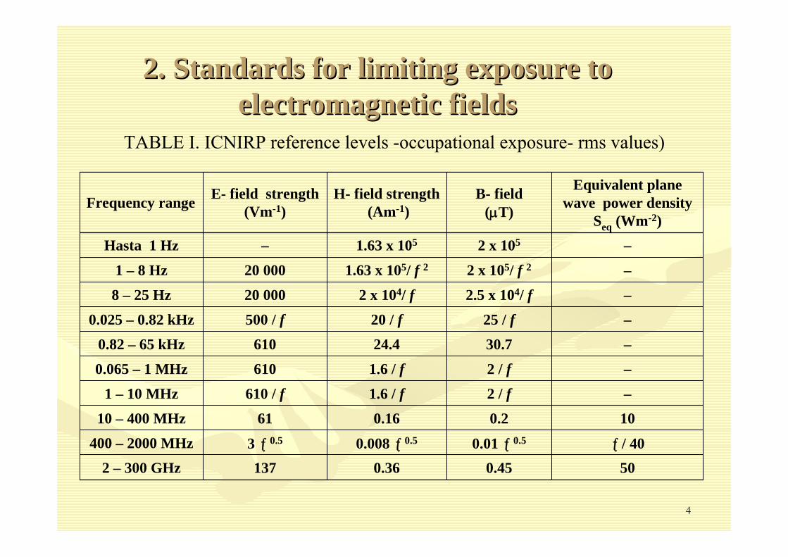
2. 2. Standards for limiting exposure to Standards for limiting exposure to electromagnetic fieldselectromagnetic fields
TABLE I. ICNIRP reference levels -occupational exposure- rms values)
TABLE III. ICNIRP reference levels for telecommunication services –general public exposure- rms values)
9.70.2060.51850- 1900 MHzPCS 1900
8.60.1956.91710- 1880 MHzPCS 1800
4.50.14
41.0890-960 MHzMobile Telephony 900 MHz
4.40.1440.6824-894MHz Mobile Telephony 800 MHz
4.30.1340.0806-869 MHzTrunking 800 MHz
2.00.09929.8407- 806 MHzUHF TV
2.00.09228.054- 88 MHz174- 216 MHzVHF TV
2.00.09228.088- 108 MHzFM broadcast
Equivalent plane wave power density Seq (Wm-2)
B- field (μT)
E- field strength (Vm-1)
Frequency range(MHz)Services
7
3.1 Reactive near field 3.1 Reactive near field
It is the region that is immediately surrounding the antenna andIt is the region that is immediately surrounding the antenna and where the where the reactive field predominates. The limit of region is considered treactive field predominates. The limit of region is considered to be at a distance o be at a distance of of λλ from the antenna] . The attenuation of electric field and magnfrom the antenna] . The attenuation of electric field and magnetic field is an etic field is an inverse function of the square and cube of distance respectivelyinverse function of the square and cube of distance respectively: For mobile : For mobile telephony systems the reactive near field limits is very limitedtelephony systems the reactive near field limits is very limited (some dozens of (some dozens of cm). The evaluation of these fields are only important for occupcm). The evaluation of these fields are only important for occupational exposure. ational exposure.
3.2. Reactive3.2. Reactive--radiating near field radiating near field
This region is a transition zone wherein radiating field gets anThis region is a transition zone wherein radiating field gets an increasing increasing importance compared with the reactive one. The limit of this subimportance compared with the reactive one. The limit of this sub--region is region is considered to be at 3 considered to be at 3 λλ from the antenna.from the antenna.
3. 3. FieldField regionsregions
8
3.3. Radiating near field 3.3. Radiating near field
This region only exists if the maximum dimension L of the antennThis region only exists if the maximum dimension L of the antenna is large compared a is large compared with with λλ. In this region the radiating field predominates. The field is . In this region the radiating field predominates. The field is not considered to not considered to propagate as plane waves but the electric and magnetic componentpropagate as plane waves but the electric and magnetic components of the field can be s of the field can be considered locally normal and related by the intrinsic impedanceconsidered locally normal and related by the intrinsic impedance of the medium of the medium ZZ00=377 =377 ohmiosohmios. The limit of this region is considered to be . The limit of this region is considered to be RRffff = 2L= 2L22 / / λλ
Where: Where: R is the distance between the evaluation location and the antennR is the distance between the evaluation location and the antennaaL is the greatest linear dimension of the radiating part of the L is the greatest linear dimension of the radiating part of the antennaantennaλλ is the wavelength of the electromagnetic field transmittedis the wavelength of the electromagnetic field transmitted
9
3.4. Far field (3.4. Far field (FranhouferFranhoufer regionregion))
According to the theory of electromagnetic fields the limit betwAccording to the theory of electromagnetic fields the limit between near field and far een near field and far field is located at field is located at
The field is considered to propagate as plane waves and the elecThe field is considered to propagate as plane waves and the electric and magnetic tric and magnetic components of the field are perpendicular and related by the intcomponents of the field are perpendicular and related by the intrinsic impedance of the rinsic impedance of the medium Zmedium Z00
The boundary curve between the far field and radiating near fielThe boundary curve between the far field and radiating near field is given by.d is given by.
where: where: αα: angle between the horizontal axis and the propagation directio: angle between the horizontal axis and the propagation direction n RRffff ((αα): ): FranhouferFranhoufer distance in the direction forming an angle distance in the direction forming an angle αα with the horizontal axiswith the horizontal axis
In Table IV it is summarized the main features of the field regiIn Table IV it is summarized the main features of the field regions, in Table V. it is ons, in Table V. it is shown the far field distance for mobile services and in Fig. 1. shown the far field distance for mobile services and in Fig. 1. it is presented a scheme it is presented a scheme of fields regionsof fields regions
λ≥
2
ffL2R
λα
=α22
ffcosL2)(R
10
TABLE IV. Main features of electromagnetic fields depending on TABLE IV. Main features of electromagnetic fields depending on fieldfield regionregion
0ZHE ≠
0ZHE ≠
0ZHE ≈
0ZHE =NormalS = EH2L2/ λ- ∞Radiating far-field
LocallyS ≈EH3 λ- 2L2/ λRadiating near-field
Not normalS < EH0- 3 λReactive- radiating near-field
Not normalS < EH0- λReactive near- field
Relation between E and HPower density
Distance range
TABLE V. Far field inner limit for mobile telecommunication servTABLE V. Far field inner limit for mobile telecommunication servicesices
)m(λ
2LR2
ff ≥
20.911.30218501710 - 1990739 495Kathrein
33.722.438851806 - 896DB848H90E-XY
Decibel
37.762.580851806 - 8967273.03Allgon
L(m)fc (MHz)Frequency range (MHz)
ModelFabricante
11
FIG. 1. Cross-sectional view of field regions for an antenna of 2.7 m high working at 900 MHz band
12
It is important to point out some remarks about the field regionIt is important to point out some remarks about the field regions s
(a)(a) The boundaries of the regions only depend on antenna dimensions The boundaries of the regions only depend on antenna dimensions and and wavelength, they do not depend on any case on the emitted power.wavelength, they do not depend on any case on the emitted power.
(b) In the reactive near field and reactive (b) In the reactive near field and reactive ––radiating near field regions are not radiating near field regions are not applicable the formulas for far field, but it does not necessapplicable the formulas for far field, but it does not necessarily imply that arily imply that the field strengths levels are important. the field strengths levels are important.
(c) The electric and magnetic fields for the reactive near field(c) The electric and magnetic fields for the reactive near field and reactive and reactive ––radiating near field regions could be calculated with relativelyradiating near field regions could be calculated with relatively complex complex methods and they can be measured with an spectrum analyzer and tmethods and they can be measured with an spectrum analyzer and the he appropriate antennas for every component.appropriate antennas for every component.
The main objective is to provide The main objective is to provide information in order to implement a information in order to implement a plan for protecting people from plan for protecting people from exposure levels above recommended exposure levels above recommended international or national standards. international or national standards.
The assessment of exposure could be The assessment of exposure could be done by calculation or by done by calculation or by measurements but normally both measurements but normally both evaluations are performed being the evaluations are performed being the calculation the first step before calculation the first step before measurements.measurements.
The assessment of the exposure level shall consider as general cThe assessment of the exposure level shall consider as general criteria: the worst riteria: the worst emission conditions and the simultaneous presence of several EMFemission conditions and the simultaneous presence of several EMF sources, even at sources, even at different frequencies. different frequencies.
The following parameters should be considered: The following parameters should be considered:
(a) The maximum EIRP of the antenna system for mean transmitter (a) The maximum EIRP of the antenna system for mean transmitter power.power.(b) The antenna gain G including maximum gain and beam width; (b) The antenna gain G including maximum gain and beam width; (c) The frequencies of operation; and (c) The frequencies of operation; and (d) Various characteristics of the installation, such as the ant(d) Various characteristics of the installation, such as the antenna location, antenna enna location, antenna height, beam direction, beam tilt. height, beam direction, beam tilt.
15
4.3. The installation classification schema:4.3. The installation classification schema:
Each emitter installation should be classified into the followinEach emitter installation should be classified into the following three classes: g three classes:
(a) Inherently compliant: These are sources that produce fields (a) Inherently compliant: These are sources that produce fields that comply with that comply with exposure limits at the operation frequencies a few centimeters aexposure limits at the operation frequencies a few centimeters away from the source. It way from the source. It is not necessary special precautions. (EIRP < 2W)is not necessary special precautions. (EIRP < 2W)
(b) Normally compliant: These are sources that produce EMF that (b) Normally compliant: These are sources that produce EMF that can exceed exposure can exceed exposure limits at the operation frequencies, but for normal installatiolimits at the operation frequencies, but for normal installation practices and typical use n practices and typical use the the exceedanceexceedance zone of these sources is not normally accessible to people but zone of these sources is not normally accessible to people but only to only to maintenance personnel. ITU states that normally compliant instalmaintenance personnel. ITU states that normally compliant installations include lations include antennas mounted on sufficiently tall towers or narrowantennas mounted on sufficiently tall towers or narrow--beam and only maintenance beam and only maintenance personnel who come into the close vicinity of emission antennae personnel who come into the close vicinity of emission antennae need to exercise need to exercise precaution. (Mobile telephony base stations)precaution. (Mobile telephony base stations)
(c) Provisionally compliant: These are installations that requir(c) Provisionally compliant: These are installations that require special measures to e special measures to achieve compliance which involves determination of the exposure achieve compliance which involves determination of the exposure zones and zones and measurements. (Broadcasting stations) measurements. (Broadcasting stations)
16
5.1 Simple Prediction Method to Evaluate Electromagnetic Field E5.1 Simple Prediction Method to Evaluate Electromagnetic Field Exposure xposure
The first step to calculate the exposure level is to compute theThe first step to calculate the exposure level is to compute the Maximum Equivalent Maximum Equivalent IsotropicallyIsotropically Radiated Power (Radiated Power (EIRPEIRPmaxmax) is given in Equation 1.) is given in Equation 1.
PPTxTx : Transmitter power : Transmitter power GGTxmTxm : Maximum Gain of antenna system : Maximum Gain of antenna system LLTxTx : Losses of antenna system: Losses of antenna system
The EIRP will depend on the The EIRP will depend on the EIRPEIRPmaxmax and the antenna directivity factor F(and the antenna directivity factor F(θθ).).
5. Prediction of Exposures from Base Stations5. Prediction of Exposures from Base Stations
17
Figures 3 and 4 show the parameters used in the calculation of tFigures 3 and 4 show the parameters used in the calculation of the exposure at the he exposure at the ground level and on adjacent building. ground level and on adjacent building.
FIG. 4. Exposure at an adjacent building
FIG.3. Exposure at ground level
18
(a) Exposure at ground level(a) Exposure at ground levelAccording to ITUAccording to ITU--T K.52 Recommendation the radiation centre of the antenna systemT K.52 Recommendation the radiation centre of the antenna systemis assumed to be at a height h and it is evaluated the power deis assumed to be at a height h and it is evaluated the power density at a point at a nsity at a point at a height of 2m above ground level at a distance x of the base of theight of 2m above ground level at a distance x of the base of the tower. The main he tower. The main bean of the antenna is axially symmetrical and downbean of the antenna is axially symmetrical and down----.tilted an angle . If the main bean .tilted an angle . If the main bean is parallel to ground is parallel to ground If hIf h’’=h =h –– 2m, then:2m, then:
and and
where where ρρ is the reflection coefficient.is the reflection coefficient.It is important to point out that the factor 2.56 could be replaIt is important to point out that the factor 2.56 could be replaced by 4 (that is ced by 4 (that is considering a reflection coefficient equal to 1)considering a reflection coefficient equal to 1)
⎟⎠
⎞⎜⎝
⎛=θ+= −
x'htan,x'hR 1222
φ
( ) ( ) ( ) )2.Eq(hx
EIRPF
456.2
hxEIRP
F4
1S 22
max22
max2
+φ−θ
π=
+θ
π
ρ+=
0=φ
19
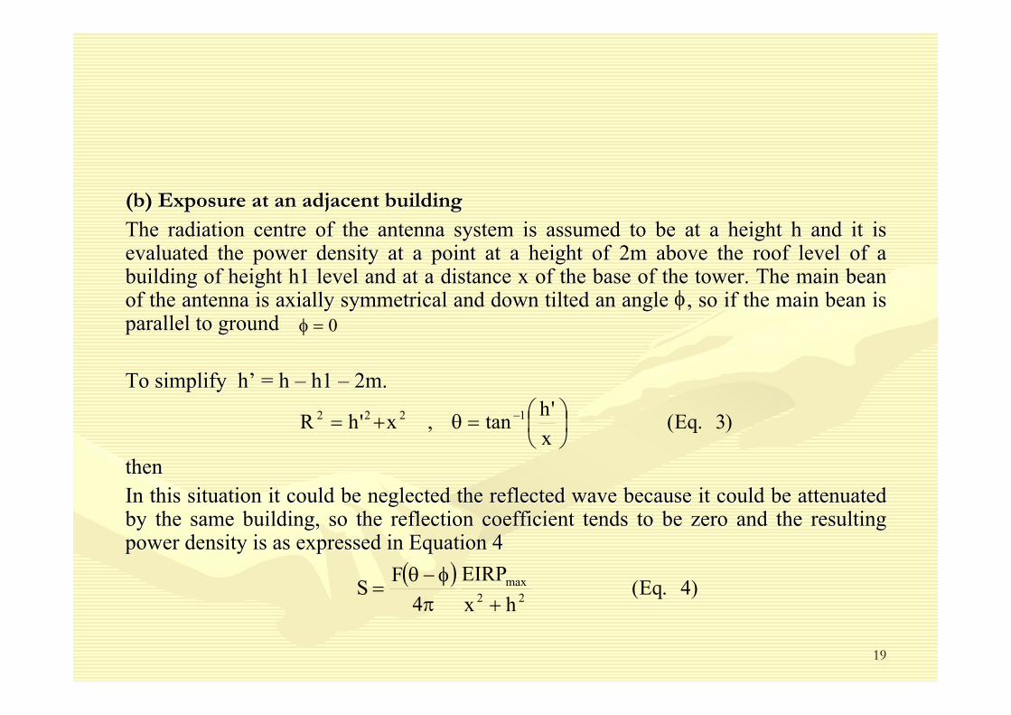
(b) Exposure at an adjacent building(b) Exposure at an adjacent building
The radiation centre of the antenna system is assumed to be at aThe radiation centre of the antenna system is assumed to be at a height h and it is height h and it is evaluated the power density at a point at a height of 2m above tevaluated the power density at a point at a height of 2m above the roof level of a he roof level of a building of height h1 level and at a distance x of the base of tbuilding of height h1 level and at a distance x of the base of the tower. The main bean he tower. The main bean of the antenna is axially symmetrical and down tilted an angle of the antenna is axially symmetrical and down tilted an angle , so if the main bean is , so if the main bean is parallel to ground parallel to ground
To To simplifysimplify hh’’ = h = h –– h1 h1 –– 2m. 2m.
then then In this situation it could be neglected the reflected wave becauIn this situation it could be neglected the reflected wave because it could be attenuated se it could be attenuated by the same building, so the reflection coefficient tends to be by the same building, so the reflection coefficient tends to be zero and the resulting zero and the resulting power density is as expressed in Equation 4power density is as expressed in Equation 4
φ0=φ
)3.Eq(x'htan,x'hR 1222 ⎟⎠⎞
⎜⎝⎛=θ+= −
( ) )4.Eq(hx
EIRP4
FS 22max
+πφ−θ
=
20
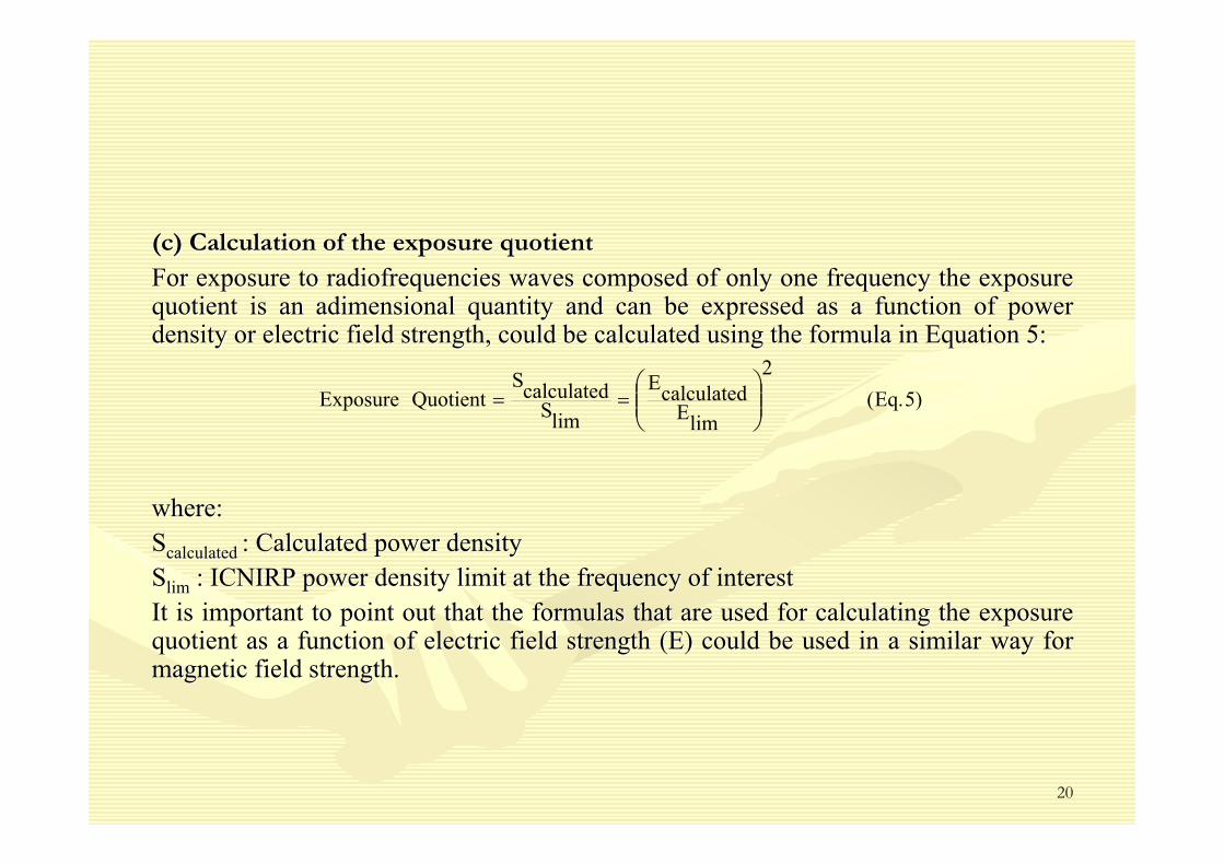
(c) Calculation of the exposure quotient(c) Calculation of the exposure quotient
For exposure to radiofrequencies waves composed of only one freqFor exposure to radiofrequencies waves composed of only one frequency the exposure uency the exposure quotient is an quotient is an adimensionaladimensional quantity and can be expressed as a function of power quantity and can be expressed as a function of power density or electric field strength, could be calculated using thdensity or electric field strength, could be calculated using the formula in Equation 5: e formula in Equation 5:
where: where: SScalculatedcalculated : Calculated power density : Calculated power density SSlimlim : ICNIRP power density limit at the frequency of interest: ICNIRP power density limit at the frequency of interestIt is important to point out that the formulas that are used forIt is important to point out that the formulas that are used for calculating the exposure calculating the exposure quotient as a function of electric field strength (E) could be uquotient as a function of electric field strength (E) could be used in a similar way for sed in a similar way for magnetic field strength. magnetic field strength.
)5.Eq(2
limEcalculatedE
limScalculatedS
QuotientExposure ⎟⎟⎠
⎞⎜⎜⎝
⎛==
21
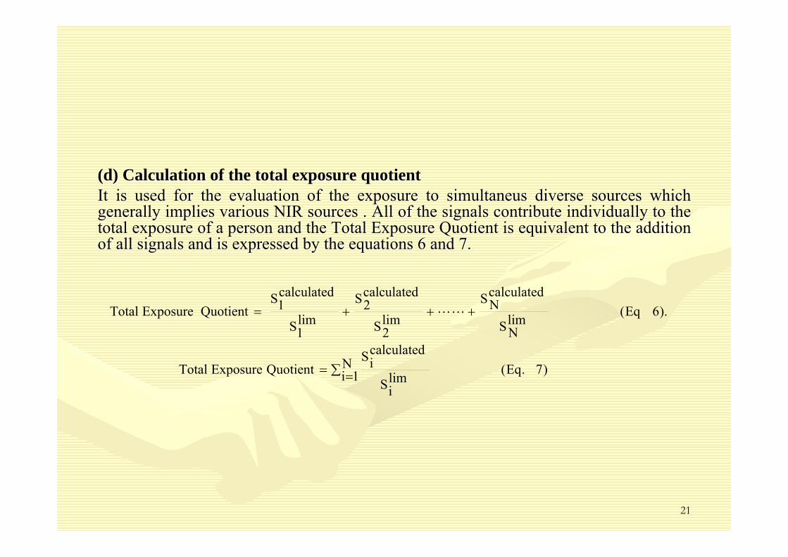
(d) Calculation of the total exposure quotient (d) Calculation of the total exposure quotient It is used for the evaluation of the exposure to It is used for the evaluation of the exposure to simultaneussimultaneus diverse sources which diverse sources which generally implies various NIR sources . All of the signals contrgenerally implies various NIR sources . All of the signals contribute individually to the ibute individually to the total exposure of a person and the Total Exposure Quotient is eqtotal exposure of a person and the Total Exposure Quotient is equivalent to the addition uivalent to the addition of all signals and is expressed by the equations 6 and 7. of all signals and is expressed by the equations 6 and 7.
)7.Eq(N1i lim
iS
calculatediS
QuotientExposureTotal
).6Eq(limNS
calculatedNS
lim2S
calculated2S
lim1S
calculated1S
QuotientExposureTotal
∑ ==
+++= LL
22
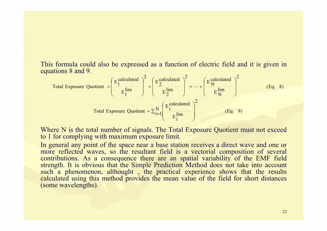
This formula could also be expressed as a function of electric fThis formula could also be expressed as a function of electric field and it is given in ield and it is given in equations 8 and 9. equations 8 and 9.
Where N is the total number of signals. The Total Exposure QuotiWhere N is the total number of signals. The Total Exposure Quotient must not exceed ent must not exceed to 1 for complying with maximum exposure limit.to 1 for complying with maximum exposure limit.In general any point of the space near a base station receives aIn general any point of the space near a base station receives a direct wave and one or direct wave and one or more reflected waves, so the resultant field is a more reflected waves, so the resultant field is a vectorialvectorial composition of several composition of several contributions. As a consequence there are an spatial variabilitycontributions. As a consequence there are an spatial variability of the EMF field of the EMF field strength. It is obvious that the Simple Prediction Method does nstrength. It is obvious that the Simple Prediction Method does not take into account ot take into account such a phenomenon, such a phenomenon, althoughtalthought , the practical experience shows that the results , the practical experience shows that the results calculated using this method provides the mean value of the fielcalculated using this method provides the mean value of the field for short distances d for short distances (some wavelengths).(some wavelengths).
)9.Eq(
2N
1i limi
calculatediQuotientExposureTotal
)8.Eq(
2
limN
calculatedN
2
lim2
calculated2
2
lim1
calculated1QuotientExposureTotal
∑ = Ε
Ε=
Ε
Ε++
Ε
Ε+
Ε
Ε=
⎟⎟⎟
⎠
⎞
⎜⎜⎜
⎝
⎛
⎟⎟
⎠
⎞
⎜⎜
⎝
⎛
⎟⎟
⎠
⎞
⎜⎜
⎝
⎛
⎟⎟
⎠
⎞
⎜⎜
⎝
⎛L
23
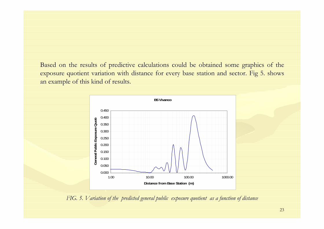
Based on the results of predictive calculations could be obtaineBased on the results of predictive calculations could be obtained some graphics of the d some graphics of the exposure quotient variation with distance for every base stationexposure quotient variation with distance for every base station and sector. Fig 5. shows and sector. Fig 5. shows an example of this kind of results.an example of this kind of results.
FIG. 5. Variation of the predicted general public exposure quoFIG. 5. Variation of the predicted general public exposure quotient as a function of distancetient as a function of distance
BS Vivanco
0.000
0.050
0.100
0.150
0.200
0.250
0.300
0.350
0.400
0.450
1.00 10.00 100.00 1000.00
Distance from Base Station (m)
Gen
eral
Pub
lic E
xpos
ure
Quo
tie
24
6. Exposure Measurement6. Exposure Measurement6.1 Site Analysis 6.1 Site Analysis It is necessary to clearly identify the measurement regions in oIt is necessary to clearly identify the measurement regions in order to restrict the rder to restrict the measurements to only one of the components electric (E) or magnemeasurements to only one of the components electric (E) or magnetic (H). This objective tic (H). This objective can be met by assuring far field conditions otherwise it is nececan be met by assuring far field conditions otherwise it is necessary to measure both of ssary to measure both of the fields. the fields. Measurement of electromagnetic fields from telecommunications muMeasurement of electromagnetic fields from telecommunications must be performed st be performed according to telecommunications service and the purpose of the eaccording to telecommunications service and the purpose of the evaluation. In most of valuation. In most of the cases the measurement will be done in the far field region othe cases the measurement will be done in the far field region or in the worst case in the r in the worst case in the radiating near field, so it is only necessary to measure E fieldradiating near field, so it is only necessary to measure E field..
45 cm1900 MHz GSM mobile communications90 cm900 MHz GSM mobile communications1.5 mUHF TV broadcasting4.5 mHigh band VHF TV broadcasting18 m Low band VHF TV broadcasting 9 m FM radiobroadcast
Approx. distance to radiating near field (3λ)Telecommunication service
TABLE VI. Distances for radiating near field for telecommunicatiTABLE VI. Distances for radiating near field for telecommunication serviceson services
25
6.2. Types of measurements6.2. Types of measurementsThere are two types of measurements could be carried out: There are two types of measurements could be carried out:
6.2.1. Broadband measurement6.2.1. Broadband measurementIn broadband measurements the total contribution over a large frIn broadband measurements the total contribution over a large frequency range is obtained equency range is obtained without distinction of the contribution of different sources opewithout distinction of the contribution of different sources operating at different rating at different frequencies.frequencies.
Limited sensitivity, so the broadband meters are often used for Limited sensitivity, so the broadband meters are often used for compliance assessment. compliance assessment. (Typical sensitivity of around 0.1 V/m)(Typical sensitivity of around 0.1 V/m)
It is recommended to use it for making measurements at locationIt is recommended to use it for making measurements at locations where the exposure s where the exposure quotient is dominated by emissions from the base station of intequotient is dominated by emissions from the base station of interest which has to be proven rest which has to be proven with narrow band measurementswith narrow band measurements
26
The probe generally consists of shortThe probe generally consists of short--electric electric dipoles (or loops) that detect the field. dipoles (or loops) that detect the field.
Isotropic probes measure the field components in Isotropic probes measure the field components in the three orthogonal directions in space and the three orthogonal directions in space and calculate the magnitude of the resultant field calculate the magnitude of the resultant field strength and thus facilitating the assessment strength and thus facilitating the assessment procedure. procedure.
On the field meter, the value obtained is shown On the field meter, the value obtained is shown as as rmsrms or peak value, or as a percentage of a or peak value, or as a percentage of a standard (ICNIRP or IEEE)standard (ICNIRP or IEEE)
FIG. 6. Electromagnetic field FIG. 6. Electromagnetic field analyzer and its electric field probeanalyzer and its electric field probe
27
(a) Advantages(a) Advantages••Broadband frequency range coverage which depends on the meter anBroadband frequency range coverage which depends on the meter and the probe to be d the probe to be used used
••Isotropic directivity Isotropic directivity ••Measurements are simple and less time Measurements are simple and less time ––consuming than narrowconsuming than narrow--band band measurements.measurements.
••Some meters are designed with frequency response shaped to meet Some meters are designed with frequency response shaped to meet the frequency the frequency variation of a particular international or national guideline (Ivariation of a particular international or national guideline (ICNIRP, IEEE) given the CNIRP, IEEE) given the fields levels as a exposure quotient.fields levels as a exposure quotient.
(b) Limitations(b) Limitations••These instruments are relatively insensitive, but they are gettiThese instruments are relatively insensitive, but they are getting better the typical ng better the typical sensitivity is around 0.1 V/m.sensitivity is around 0.1 V/m.
••General public exposures They are unable to responds to rapid siGeneral public exposures They are unable to responds to rapid signal changes due to gnal changes due to modulation, access mode and for base stations are near or below modulation, access mode and for base stations are near or below the detection the detection threshold threshold difficultingdifficulting reliable measurements. reliable measurements.
••Lack of frequency selectivity so the results could be the additiLack of frequency selectivity so the results could be the addition of several signals. on of several signals.
28
(c) Measurement uncertainty (accuracy) :The main sources of uncertainty or broadband measurements are linked to:
•Electrical factors: Linked to the calibration of the field analyzer and its probe. The calibration certificate provides information on isotropic value and its uncertainty. The data sheet provides information on calibration factor, frequency response, linearity, drift and their uncertainties
•Factors coming from measurement practices: During measurement the electromagnetic field analyzer with its probe is mounted on a tripod and the measurement is performed without no contact with the operator, but there are additional uncertainty factor which depend on the coupling or positioning related to fixed structures or the use of the meter by hand rather than on tripod.
Total expanded uncertainty uncertainty for broadband measurement can be estimated as 3 dB.
FIG. 7. Simplified schema of setup for broadband measurementFIG. 7. Simplified schema of setup for broadband measurement
29
6.2.2. Narrow band measurement 6.2.2. Narrow band measurement Narrow band measurements allow Narrow band measurements allow distinguishing between the specific distinguishing between the specific contributions in the different frequency contributions in the different frequency ranges. They are based on the use of a ranges. They are based on the use of a spectrum analyzer in conjunction with one spectrum analyzer in conjunction with one or several different antennas according to or several different antennas according to the frequency range to evaluate: tuned the frequency range to evaluate: tuned dipoles, bidipoles, bi--conical dipoles (30conical dipoles (30--300 MHz, 300 MHz, 2020-- 600 MHz, 250600 MHz, 250-- 1000 MHz), log1000 MHz), log--periodic antennas (200periodic antennas (200--1000 MHz), horn 1000 MHz), horn antennas (1antennas (1--18 GHz), double ridge 18 GHz), double ridge waveguide horn antennas (1 waveguide horn antennas (1 --18 GHz) 18 GHz) among others.among others.
Spectrum analyzers can detect signals Spectrum analyzers can detect signals being at least 8 to 10 orders of magnitude being at least 8 to 10 orders of magnitude lower as the limits specified in the lower as the limits specified in the guidelines, standards or other documents. guidelines, standards or other documents.
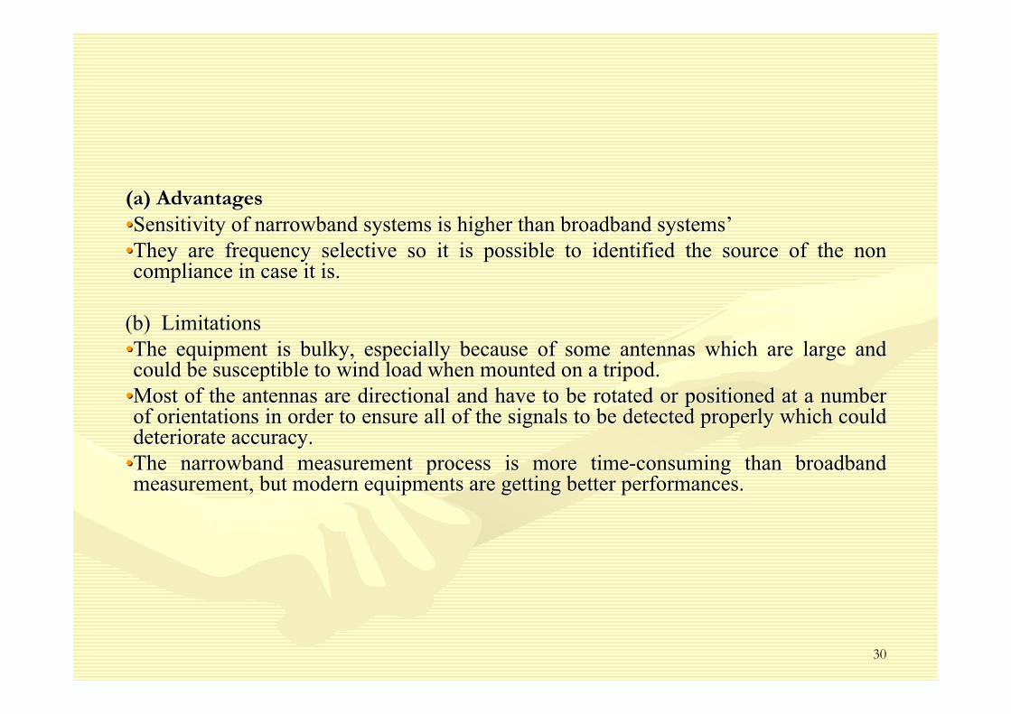
(a) Advantages(a) Advantages••Sensitivity of narrowband systems is higher than broadband systeSensitivity of narrowband systems is higher than broadband systemsms’’••They are frequency selective so it is possible to identified theThey are frequency selective so it is possible to identified the source of the non source of the non compliance in case it is.compliance in case it is.
(b) Limitations (b) Limitations ••The equipment is bulky, especially because of some antennas whicThe equipment is bulky, especially because of some antennas which are large and h are large and could be susceptible to wind load when mounted on a tripod.could be susceptible to wind load when mounted on a tripod.
••Most of the antennas are directional and have to be rotated or pMost of the antennas are directional and have to be rotated or positioned at a number ositioned at a number of orientations in order to ensure all of the signals to be deteof orientations in order to ensure all of the signals to be detected properly which could cted properly which could deteriorate accuracy. deteriorate accuracy.
••The narrowband measurement process is more timeThe narrowband measurement process is more time--consuming than broadband consuming than broadband measurement, but modern equipments are getting better performancmeasurement, but modern equipments are getting better performances. es.
31
((c) Measurement uncertaintyc) Measurement uncertaintyThe main sources of uncertainty or narrow band measurements are The main sources of uncertainty or narrow band measurements are linked to:linked to:••Electrical factors: These factors are linked to the calibration Electrical factors: These factors are linked to the calibration of the field analyzer and antennas of the field analyzer and antennas ••Factors coming from measurement practices: During measurement thFactors coming from measurement practices: During measurement the antennas are on tripods e antennas are on tripods and the measurement includes some rotations or positioning whichand the measurement includes some rotations or positioning which could result in additional could result in additional uncertainty because of the coupling or positioning related to fiuncertainty because of the coupling or positioning related to fixed structures in the vicinity or xed structures in the vicinity or the operatorthe operator’’s body.s body.Total expanded uncertainty for narrowband measurements can be eTotal expanded uncertainty for narrowband measurements can be estimated as 2 dBstimated as 2 dB
H o r n A n t e n n a 1 - 1 8 G H z
S p e c t r u m A n a l y z e r L a p t o p
C o a x i a l C a b l e
P o la r i z a t io n : A x is Y
S p e c t r u m A n a l y z e r L a p t o p
S p e c t r u m A n a l y z e rL a p t o p
L o g - P e r i o d i c A n t e n n a 2 0 0 - 1 0 0 0 M H z
D i p o l e A n t e n n a3 0 - 8 0 M H z / 8 0 - 2 3 0 M H z
T o w e r o f T e l e c o m m u n i c a t i o n s
C o a x i a l C a b l e
C o a x i a l C a b l e
P o la r iz a t io n : A x is Y
P o la r iz a t io n : A x is X
FIG. 9. Simplified schema of setup for narrowband measurementFIG. 9. Simplified schema of setup for narrowband measurement
32
6.5 Measurement Protocol6.5 Measurement Protocol
6.3.1 General considerations 6.3.1 General considerations
((a)Takinga)Taking into account the azimuths of antennas arrangement for each sectinto account the azimuths of antennas arrangement for each sector of the or of the base stations (the measurements points are located at 2, 10, 20,base stations (the measurements points are located at 2, 10, 20, 50 and 100 m from 50 and 100 m from the base of the antenna in the direction of the main beam of thethe base of the antenna in the direction of the main beam of the antennas antennas arrangement, whenever the measurements locations at these distanarrangement, whenever the measurements locations at these distances be accessible). ces be accessible).
((b)Theb)The measurements shall be made for a single point at 1.5 m over themeasurements shall be made for a single point at 1.5 m over the floor (temporal floor (temporal average). average). In order to avoid interferences and/or errors in the field measuIn order to avoid interferences and/or errors in the field measurement, the operator rement, the operator maintained a minimum distance of 2.5 m from the probe. maintained a minimum distance of 2.5 m from the probe.
((c)Thec)The average time for temporal average will depend on the standard uaverage time for temporal average will depend on the standard used to the sed to the assessment: for example for ICNIRP is 6 minutes and for IEEE is assessment: for example for ICNIRP is 6 minutes and for IEEE is 6 and 30 minutes.6 and 30 minutes.
33
((d) Depending on the measured value it could be done measurementsd) Depending on the measured value it could be done measurements for Spatial for Spatial Average along a vertical line with three measurements points locAverage along a vertical line with three measurements points located to 1.1 m, 1.5 m ated to 1.1 m, 1.5 m and 1.7 m. over the reference surface as it is illustrated in thand 1.7 m. over the reference surface as it is illustrated in the following figure:e following figure:
FIG. 10. Schema for spatial averagingFIG. 10. Schema for spatial averagingIn this case the field strength value used for further calculatiIn this case the field strength value used for further calculations is the average of the ons is the average of the three values obtained for each spatial point., as it is shown inthree values obtained for each spatial point., as it is shown in equations 10 and 11.equations 10 and 11.
)10.Eq(3
EE
3
1i
2i
averagespatial
∑=
− =
)11.Eq(3
SS
3
1ii
averagespatial
∑=
− =
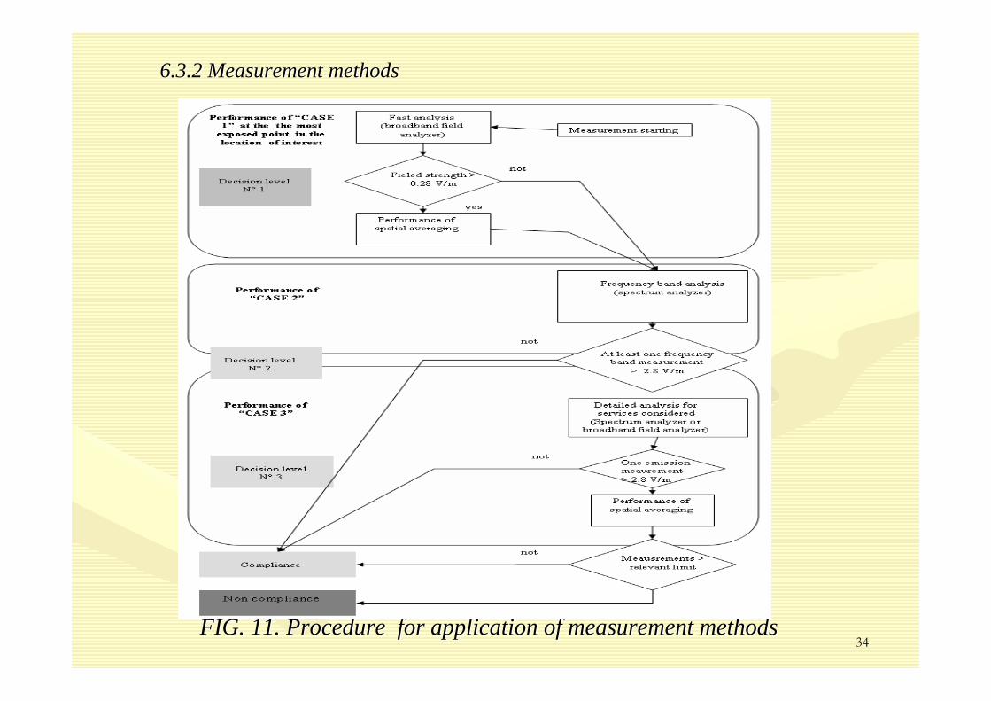
34FIG. 11. Procedure for application of measurement methodsFIG. 11. Procedure for application of measurement methods
6.3.3 Quick overview method6.3.3 Quick overview methodThis method is based on broadband measurement and basically is aThis method is based on broadband measurement and basically is aimed to evaluate imed to evaluate compliance with NIR standards, so it can not be applied in the fcompliance with NIR standards, so it can not be applied in the following cases.ollowing cases.When it is necessary to know the contributions of different sourWhen it is necessary to know the contributions of different sources by frequency.ces by frequency.If the equipment threshold is of the same order of expected measIf the equipment threshold is of the same order of expected measurement values.urement values.(a) Measurement procedure(a) Measurement procedureThe equipment that it is necessary to use is the same as expressThe equipment that it is necessary to use is the same as expressed in ..ed in ..Choose of the most suitable probes for the frequencies of intereChoose of the most suitable probes for the frequencies of interest.st.The choice of the points shall be according to general consideraThe choice of the points shall be according to general considerationstionsIn some cases, it could be necessary two or more probes in this In some cases, it could be necessary two or more probes in this case the total values are case the total values are given by the equations given by the equations equationsequations 12 and 13.12 and 13.
where n is the number of probes covering the frequency band of iwhere n is the number of probes covering the frequency band of interest and nterest and EEii y y SSii are are the values obtained for each probe. the values obtained for each probe.
)12.Eq(EEn
1i
2itotal ∑
==
)13.Eq(SSn
1iitotal ∑
==
36
(b) Post(b) Post-- processing processing If the value is below the threshold sensitivity of the probe, thIf the value is below the threshold sensitivity of the probe, the value has to be e value has to be discarded.discarded.A probe specific correction factor may be applied according to mA probe specific correction factor may be applied according to manufacturersanufacturers’’instructions.instructions.In order to relate the different quantities measured it could beIn order to relate the different quantities measured it could be used the formula in used the formula in Equation 14.Equation 14.
In case of multipleIn case of multiple--frequency exposure it is necessary to applied equations 15 and 1frequency exposure it is necessary to applied equations 15 and 166
)14.Eq(ZHZEEHS 0
2
0
2
===
)15.Eq(EEn
1i
2itotal ∑
==
)16.Eq(SSn
1iitotal ∑
==
37
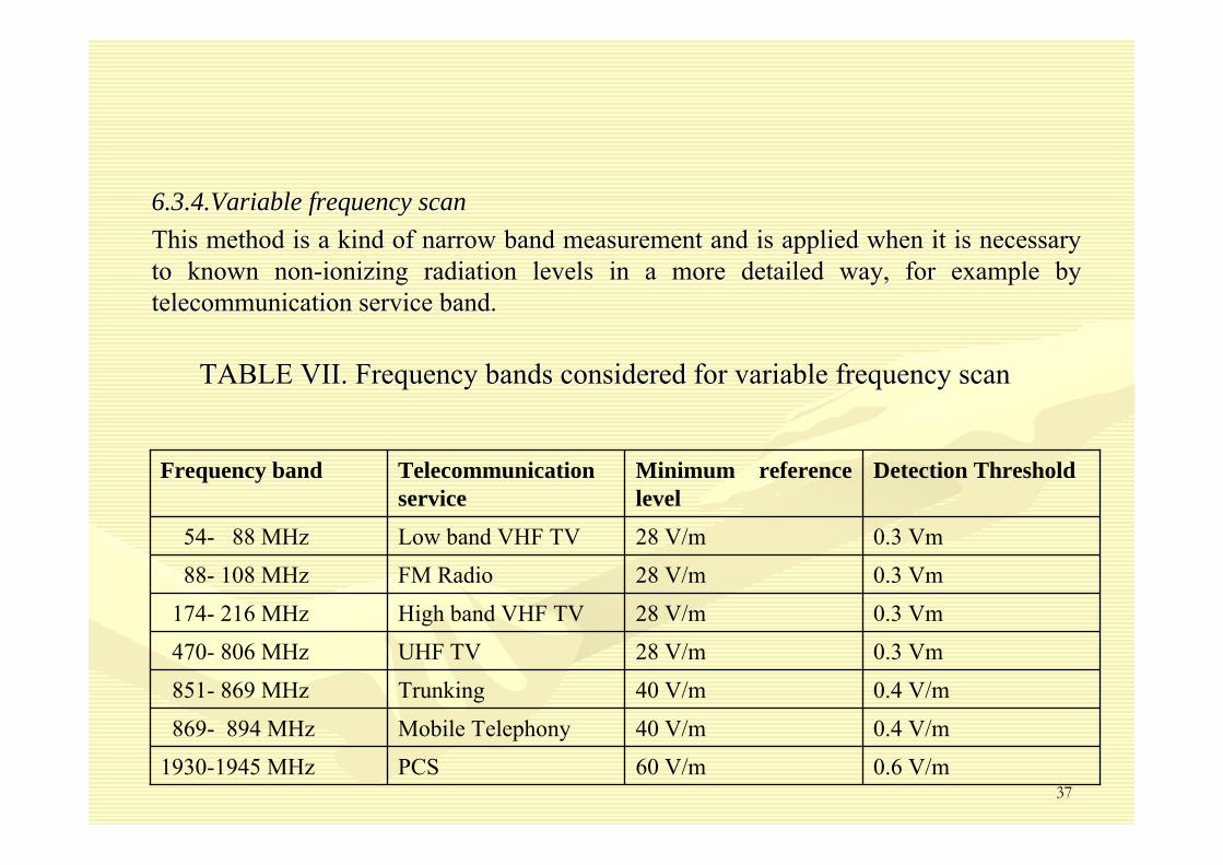
6.3.4.Variable frequency scan6.3.4.Variable frequency scanThis method is a kind of narrow band measurement and is applied This method is a kind of narrow band measurement and is applied when it is necessary when it is necessary to known nonto known non--ionizing radiation levels in a more detailed way, for example byionizing radiation levels in a more detailed way, for example bytelecommunication service band.telecommunication service band.
0.6 V/m60 V/mPCS1930-1945 MHz
0.4 V/m40 V/mMobile Telephony869- 894 MHz
0.4 V/m40 V/mTrunking851- 869 MHz
0.3 Vm28 V/mUHF TV470- 806 MHz
0.3 Vm28 V/mHigh band VHF TV174- 216 MHz
0.3 Vm28 V/mFM Radio88- 108 MHz
0.3 Vm28 V/mLow band VHF TV54- 88 MHz
Detection ThresholdMinimum reference level
Telecommunication service
Frequency band
TABLE VII. Frequency bands considered for variable frequency scaTABLE VII. Frequency bands considered for variable frequency scann
38
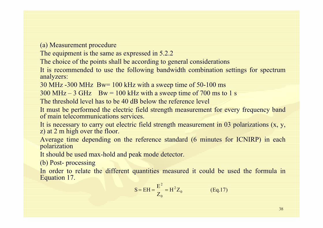
(a) Measurement procedure(a) Measurement procedureThe equipment is the same as expressed in 5.2.2The equipment is the same as expressed in 5.2.2The choice of the points shall be according to general consideraThe choice of the points shall be according to general considerationstionsIt is recommended to use the following bandwidth combination setIt is recommended to use the following bandwidth combination settings for spectrum tings for spectrum analyzers:analyzers:30 MHz 30 MHz --300 MHz 300 MHz BwBw= 100 kHz with a sweep time of 50= 100 kHz with a sweep time of 50--100 ms100 ms300 MHz 300 MHz –– 3 GHz 3 GHz BwBw = 100 kHz with a sweep time of 700 ms to 1 s= 100 kHz with a sweep time of 700 ms to 1 sThe threshold level has to be 40 dB below the reference levelThe threshold level has to be 40 dB below the reference levelIt must be performed the electric field strength measurement forIt must be performed the electric field strength measurement for every frequency band every frequency band of main telecommunications services. of main telecommunications services. It is necessary to carry out electric field strength measurementIt is necessary to carry out electric field strength measurement in 03 polarizations (x, y, in 03 polarizations (x, y, z) at 2 m high over the floor.z) at 2 m high over the floor.Average time depending on the reference standard (6 minutes for Average time depending on the reference standard (6 minutes for ICNIRP) in each ICNIRP) in each polarizationpolarizationIt should be used maxIt should be used max--hold and peak mode detector. hold and peak mode detector. (b) Post(b) Post-- processing processing In order to relate the different quantities measured it could beIn order to relate the different quantities measured it could be used the formula in used the formula in Equation 17.Equation 17.
This method should be applied in the following situations:This method should be applied in the following situations:••Where near field measurements are required. Where near field measurements are required. ••Where measurements of strong electric or magnetic fields are reqWhere measurements of strong electric or magnetic fields are required. uired. ••When it is necessary to measure pulsed, discontinuous or wideWhen it is necessary to measure pulsed, discontinuous or wide--band signals. band signals. ••If one of the total exposure quotients exceed the value If one of the total exposure quotients exceed the value ““11””..
(a) Measurement procedure (a) Measurement procedure ••It could be use both types of equipment; broad band and narrow bIt could be use both types of equipment; broad band and narrow band meters. and meters. ••The choice of the points shall be according to general consideraThe choice of the points shall be according to general considerations.tions.••For spectrum analyzers it is recommended to use the following baFor spectrum analyzers it is recommended to use the following bandwidth ndwidth combination settings:combination settings:30 MHz 30 MHz --300 MHz, 300 MHz, BwBw= 100 kHz with a sweep time of 50= 100 kHz with a sweep time of 50--100 ms100 ms300 MHz 300 MHz –– 3 GHz , 3 GHz , BwBw = 100 kHz with a sweep time of 700 ms to 1 s= 100 kHz with a sweep time of 700 ms to 1 s
The threshold level has to be 40 dB below the reference levelThe threshold level has to be 40 dB below the reference level
40
Reactive near Reactive near ––field measurementfield measurement••It could be done by broadband or narrow band measurements. In anIt could be done by broadband or narrow band measurements. In any case it is y case it is necessary to independently measure the Enecessary to independently measure the E--field and the Hfield and the H--field. field.
••For broadband measurements it is necessary to use probes for eleFor broadband measurements it is necessary to use probes for electric and magnetic ctric and magnetic fields. fields.
••For narrowband measurements of E field it could be used dipole, For narrowband measurements of E field it could be used dipole, bibi--conical, logconical, log--periodic and horn antennas among others and for measuring Hperiodic and horn antennas among others and for measuring H--field it is usually used field it is usually used loop antennas. loop antennas.
Strong electric or magnetic field measurementStrong electric or magnetic field measurement••For spectrum analyzers it is necessary to use passive antennas aFor spectrum analyzers it is necessary to use passive antennas and appropriately nd appropriately protection features. protection features.
••Set the centre frequency on each channel of the emission with a Set the centre frequency on each channel of the emission with a resolution equal or resolution equal or larger than the bandwidth of the channel. larger than the bandwidth of the channel.
••Select average mode and Select average mode and ““rmsrms detectordetector”” during the time recommended in the during the time recommended in the applicable standard.applicable standard.
••If the antenna used has a single polarization it is necessary toIf the antenna used has a single polarization it is necessary to perform the perform the measurement for the three orthogonal directions to obtain the dimeasurement for the three orthogonal directions to obtain the different components of fferent components of the field. In this case the total field is given by Equation 18 the field. In this case the total field is given by Equation 18
)18.Eq(EEEE 2z
2y
2xtotal ++=
41
Pulsed emissions measurementsPulsed emissions measurementsFor this type of signals, the energy is carried in short bursts For this type of signals, the energy is carried in short bursts and the pulse is usually and the pulse is usually short compared to the signal period. The power peak usually rangshort compared to the signal period. The power peak usually ranges form 1 W to 50 es form 1 W to 50 MW and it is necessary to assess the peak and the MW and it is necessary to assess the peak and the rmsrms level.level.
For the assessment of the peak valueFor the assessment of the peak value••Choose a frequency band enough to cope with impulse bandwidth Choose a frequency band enough to cope with impulse bandwidth ••Select maxSelect max--hold mode for 1 or several rotations of the radar (until stabilihold mode for 1 or several rotations of the radar (until stabilization of zation of signal)signal)
••Select Select ““positive peak detection modepositive peak detection mode””••The peak power should not exceed the reference by a 1000 factor The peak power should not exceed the reference by a 1000 factor for power density or for power density or 32 for field strength 32 for field strength
For the evaluation of For the evaluation of rmsrms field strength field strength ••Carried out the average of the instantaneous signal in the Carried out the average of the instantaneous signal in the rmsrms mode.mode.••Emission from mobile communications Emission from mobile communications ••As these systems consist of a permanent control channel and trafAs these systems consist of a permanent control channel and traffic channels. A base fic channels. A base station could be understood as n transmitters. station could be understood as n transmitters.
••In order to perform the measurement it could used the control chIn order to perform the measurement it could used the control channel (identified with annel (identified with a spectrum analyzer because of its features: permanence and staba spectrum analyzer because of its features: permanence and stable level). le level).
••Select centre frequency with resolution equal or larger to the bSelect centre frequency with resolution equal or larger to the bandwidth of the andwidth of the channel, max hold mode and peak detectorchannel, max hold mode and peak detector
••If the antenna used has a single polarization it is necessary toIf the antenna used has a single polarization it is necessary to perform the perform the measurement for the three orthogonal directions to obtain the dimeasurement for the three orthogonal directions to obtain the different components of fferent components of the field. In this case the total field is given by the Equationthe field. In this case the total field is given by the Equation 19 19
)19.Eq(EEEE 2z
2y
2xtotal ++=
42
Obtain the data of the number of transmitter for maximum load.Obtain the data of the number of transmitter for maximum load.The maximum traffic field strength is calculated by the EquatioThe maximum traffic field strength is calculated by the Equation 22:n 22:
If the transmitters are using different power levels from controIf the transmitters are using different power levels from control channel it has to be l channel it has to be applied the Equation 23applied the Equation 23::
)20.Eq(nEE maxrstrasnmittechannelcontorlmax −−=
)21.Eq(P
PEE
channelcontrol
totalchannelcontorlmax
−−=
43
There are two basic guidelines for non-ionizing radiations: ICNIRP guidelines and IEEE standards, being the ICNIRP guidelines the most accepted one.
There are two basic types of measurements for radiofrequency sources from telecommunications: broadband and narrowband
The broadband measurements are aimed to test compliance including all of the sources in the location which is tested. This type of measurements is not very sensitive so sometimes it is not very useful.
The narrowband measurements are aimed to know the sources of different emissions because is frequency selective. This type of measurement is very sensitive and could measure levels orders of magnitude below the international exposure limits.
There are three kind of measurement methods: Quick overview, Variable frequency scan and Detailed investigation.
Levels of exposure coming from base stations are very low typically 100 to 1000 times below international limits