An RC integrator is a circuit that approximates the mathematical process of integration. Integration is a summing process, and a basic integrator can produce an output that is a running sum of the input under certain conditions. A basic RC integrator circuit is simply a capacitor in series with a resistor and the source. The output is taken across the capacitor. V S R C V out The RC Integrator
Transcript
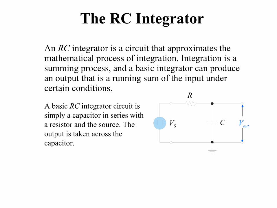
An RC integrator is a circuit that approximates the mathematical process of integration. Integration is a summing process, and a basic integrator can produce an output that is a running sum of the input under certain conditions.
A basic RC integrator circuit is simply a capacitor in series with a resistor and the source. The output is taken across the capacitor.
VS
R
C Vout
The RC Integrator
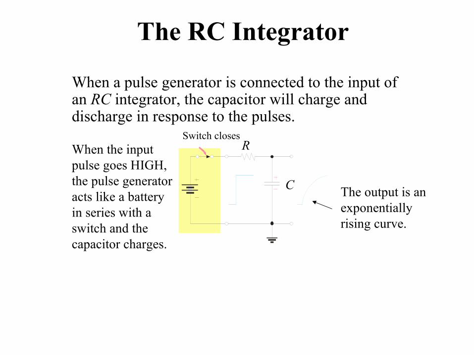
When a pulse generator is connected to the input of an RC integrator, the capacitor will charge and discharge in response to the pulses.
When the input pulse goes HIGH, the pulse generator acts like a battery in series with a switch and the capacitor charges.
Switch closes
The output is an exponentially rising curve.
R
C
The RC Integrator
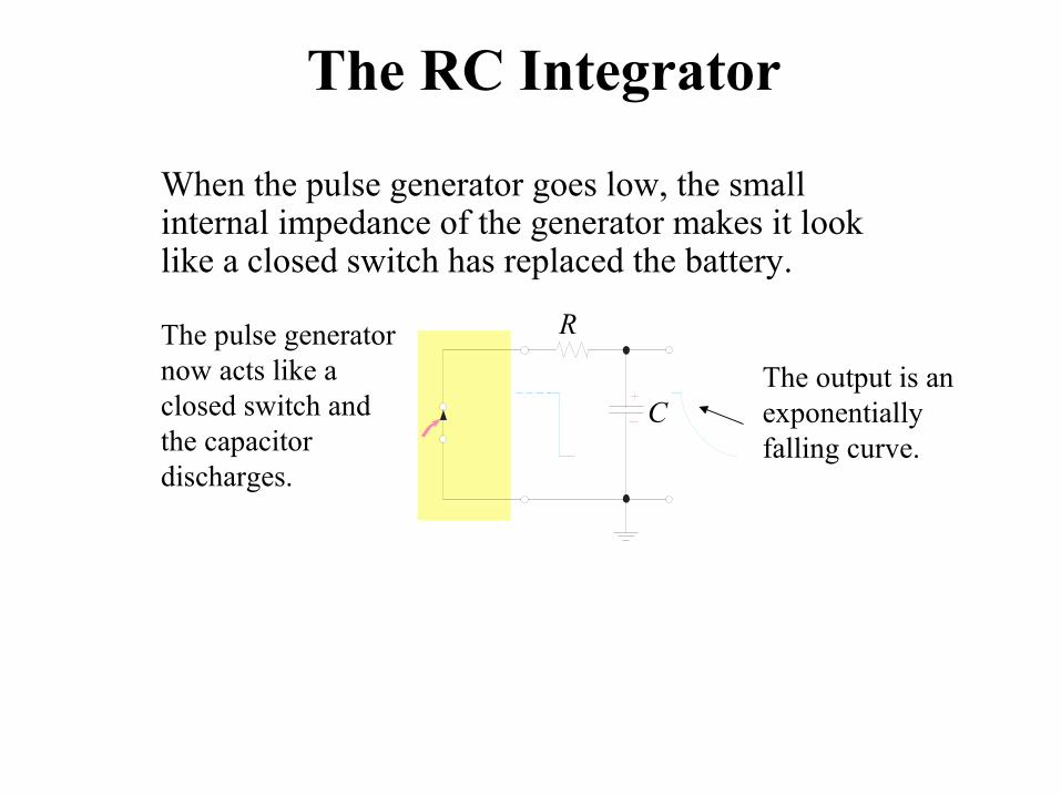
When the pulse generator goes low, the small internal impedance of the generator makes it look like a closed switch has replaced the battery.
The output is an exponentially falling curve.
R
C
The pulse generator now acts like a closed switch and the capacitor discharges.
The RC Integrator
Examples
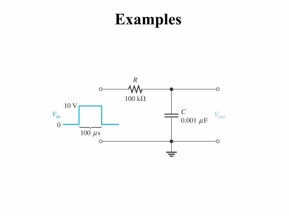
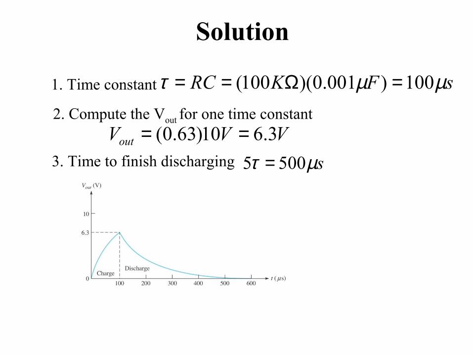
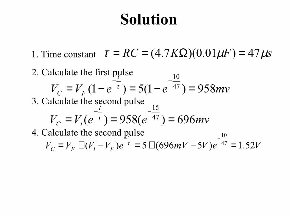
sFKRC µµτ 100)001.0)(100( =Ω==1. Time constant
2. Compute the Vout for one time constant
3. Time to finish discharging sµτ 5005 =VVVout 3.610)63.0( ==
Solution
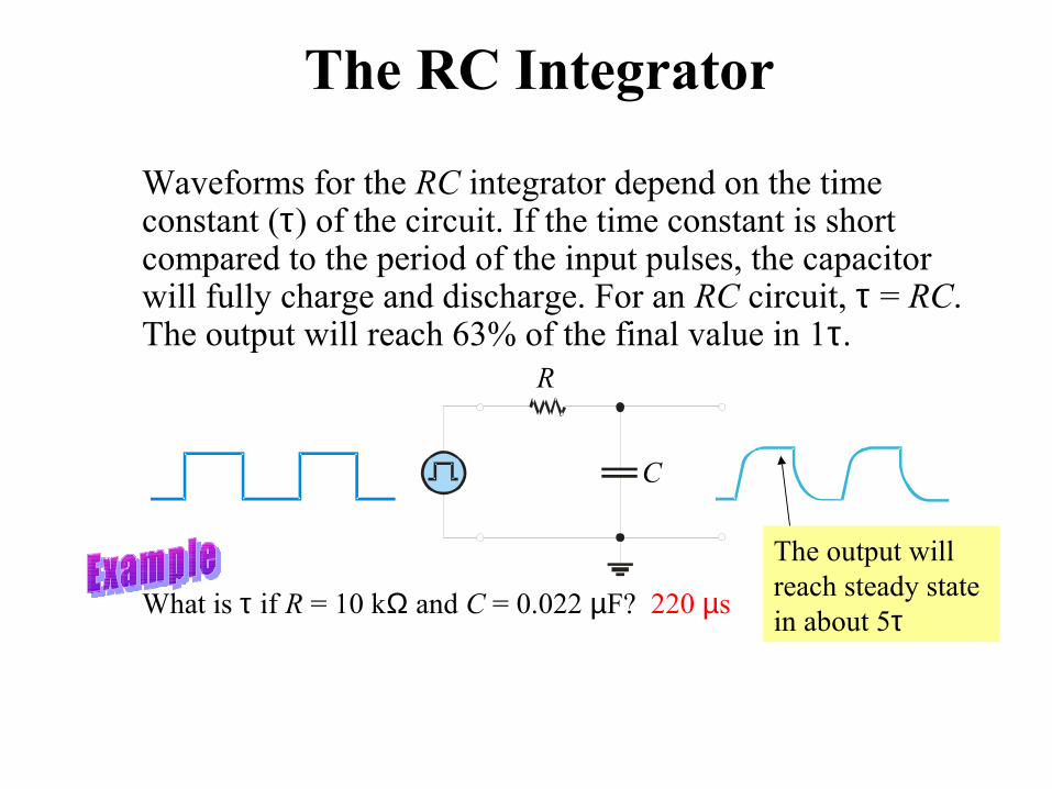
Waveforms for the RC integrator depend on the time constant (τ) of the circuit. If the time constant is short compared to the period of the input pulses, the capacitor will fully charge and discharge. For an RC circuit, τ = RC. The output will reach 63% of the final value in 1τ.
R
C
What is τ if R = 10 kΩ and C = 0.022 µF? 220 µs
The output will reach steady state in about 5τ
The RC Integrator
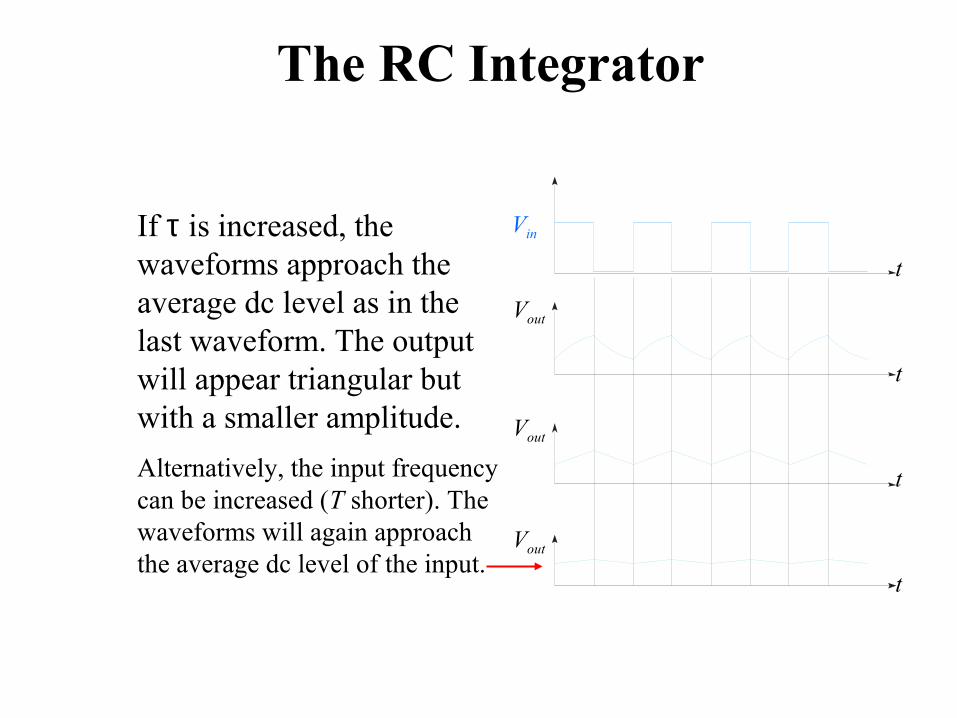
If τ is increased, the waveforms approach the average dc level as in the last waveform. The output will appear triangular but with a smaller amplitude.
Alternatively, the input frequency can be increased (T shorter). The waveforms will again approach the average dc level of the input.
t
t
t
t
Vin
Vout
Vout
Vout
The RC Integrator
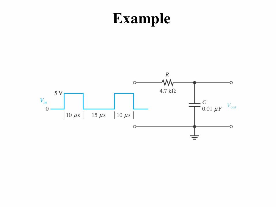
Example
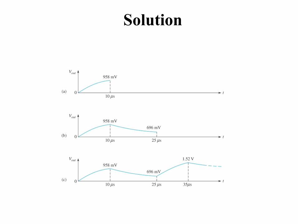
sFKRC µµτ 47)01.0)(7.4( =Ω==1. Time constant
2. Calculate the first pulse
3. Calculate the second pulsemveeVV
t
FC 958)1(5)1( 47
10
=−=−=−−
τ
mveeVVt
iC 696)(958)( 47
15
===−−
τ
4. Calculate the second pulseVeVmVeVVVV
t
FiFC 52.1)5696(5)( 47
10
=−+=−+=−−
τ
Solution
Solution
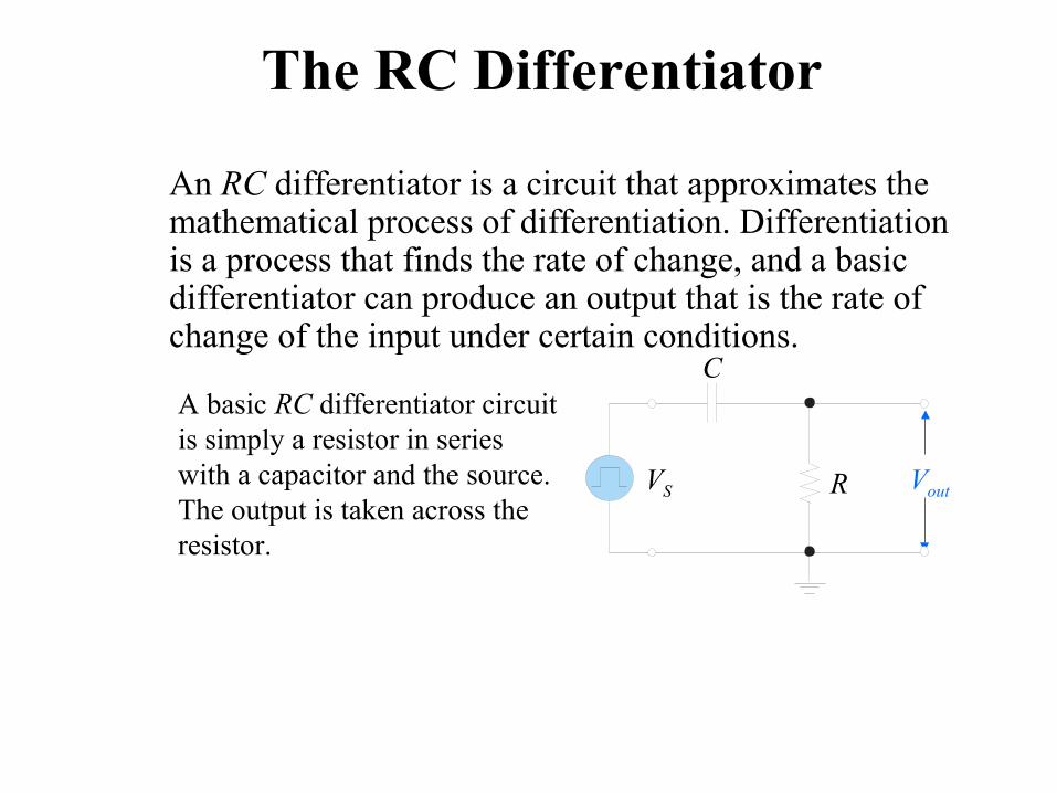
An RC differentiator is a circuit that approximates the mathematical process of differentiation. Differentiation is a process that finds the rate of change, and a basic differentiator can produce an output that is the rate of change of the input under certain conditions.
A basic RC differentiator circuit is simply a resistor in series with a capacitor and the source. The output is taken across the resistor.
VS R
C
Vout
The RC Differentiator
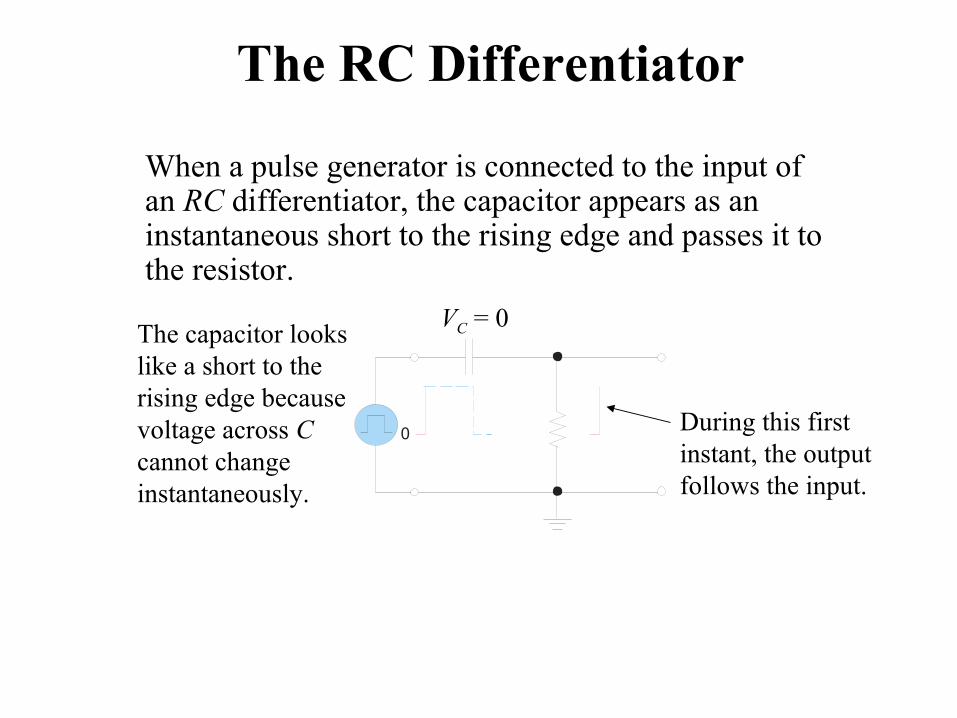
When a pulse generator is connected to the input of an RC differentiator, the capacitor appears as an instantaneous short to the rising edge and passes it to the resistor.
The capacitor looks like a short to the rising edge because voltage across C cannot change instantaneously.
During this first instant, the output follows the input.
0
VC = 0
The RC Differentiator
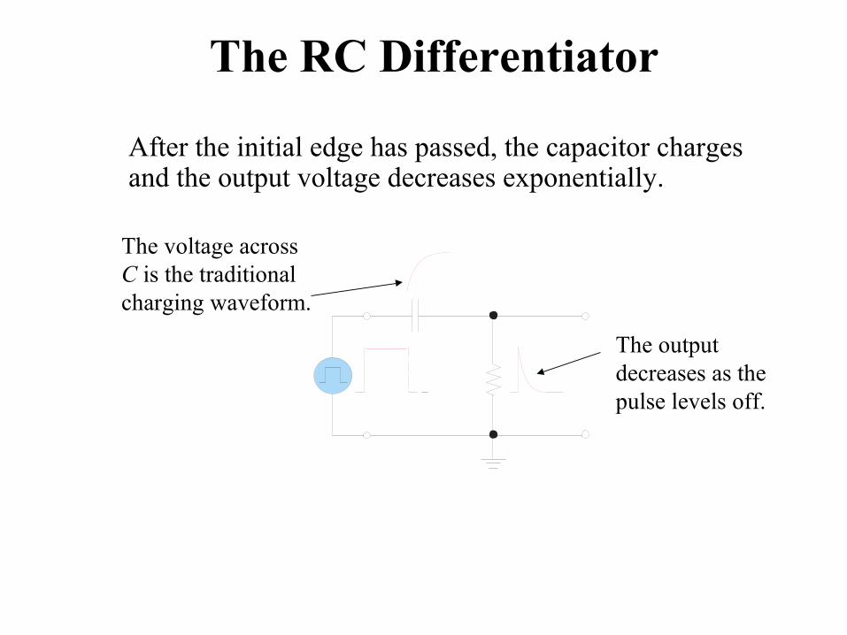
After the initial edge has passed, the capacitor charges and the output voltage decreases exponentially.
The voltage across C is the traditional charging waveform.
The output decreases as the pulse levels off.
The RC Differentiator
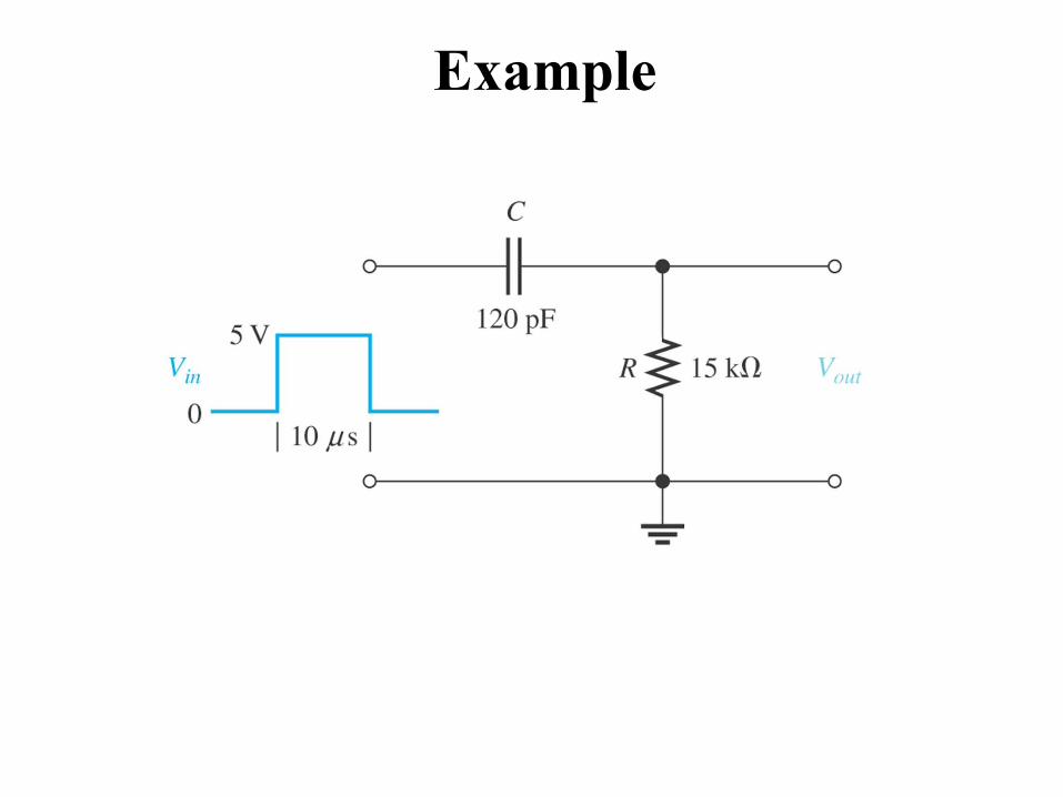
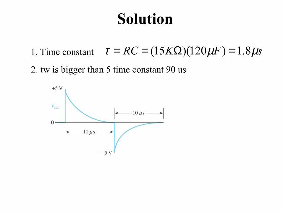
Example
sFKRC µµτ 8.1)120)(15( =Ω==1. Time constant
2. tw is bigger than 5 time constant 90 us
Solution
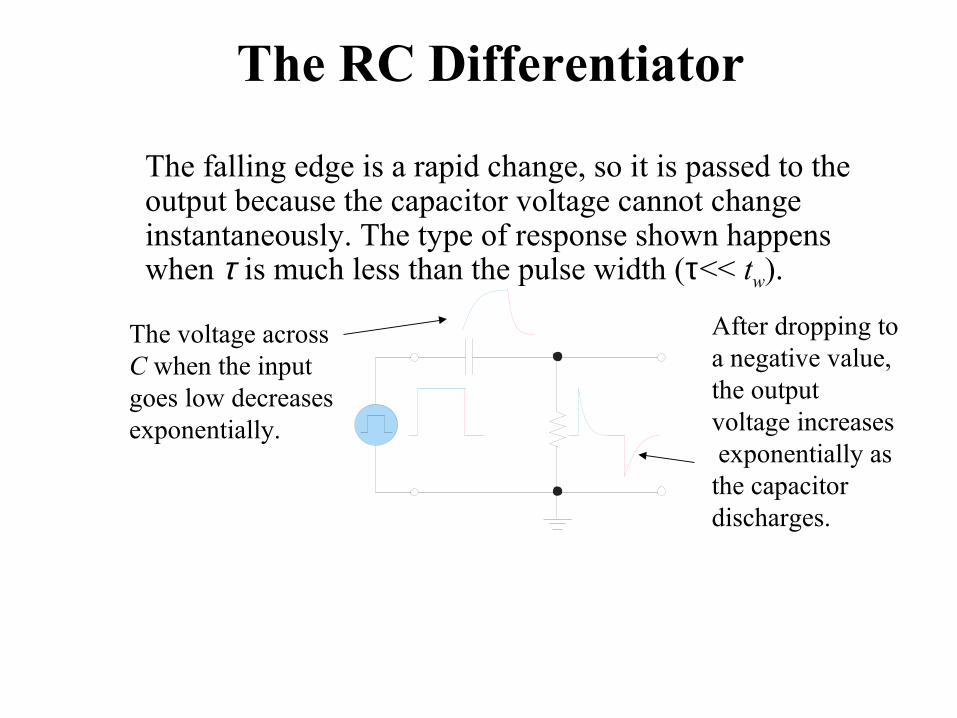
The falling edge is a rapid change, so it is passed to the output because the capacitor voltage cannot change instantaneously. The type of response shown happens when τ is much less than the pulse width (τ<< tw).
The voltage across C when the input goes low decreases exponentially.
After dropping to a negative value, the output voltage increases exponentially as the capacitor discharges.
The RC Differentiator
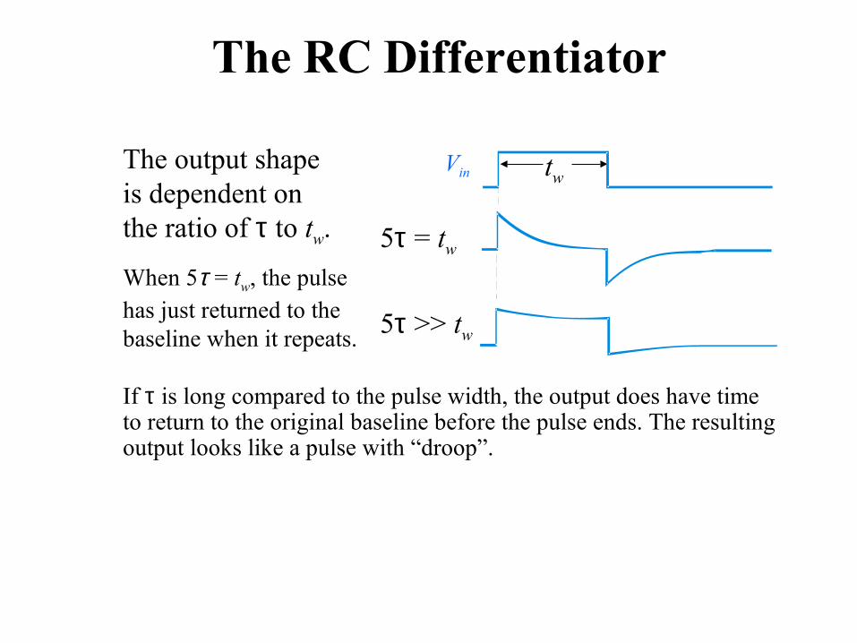
If τ is long compared to the pulse width, the output does have time to return to the original baseline before the pulse ends. The resulting output looks like a pulse with “droop”.
Vin
5τ = tw
5τ >> tw
tw
When 5τ = tw, the pulse has just returned to the baseline when it repeats.
The output shape is dependent on the ratio of τ to tw.
The RC Differentiator
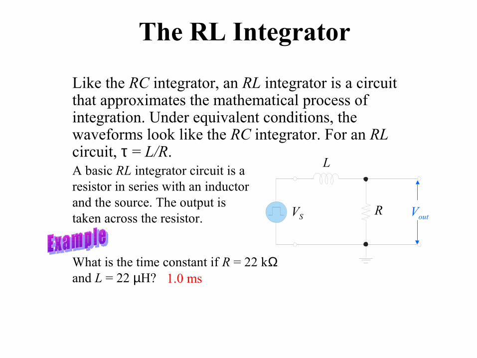
Like the RC integrator, an RL integrator is a circuit that approximates the mathematical process of integration. Under equivalent conditions, the waveforms look like the RC integrator. For an RL circuit, τ = L/R.A basic RL integrator circuit is a resistor in series with an inductor and the source. The output is taken across the resistor. VS
R
L
Vout
What is the time constant if R = 22 kΩ and L = 22 µH? 1.0 ms
The RL Integrator
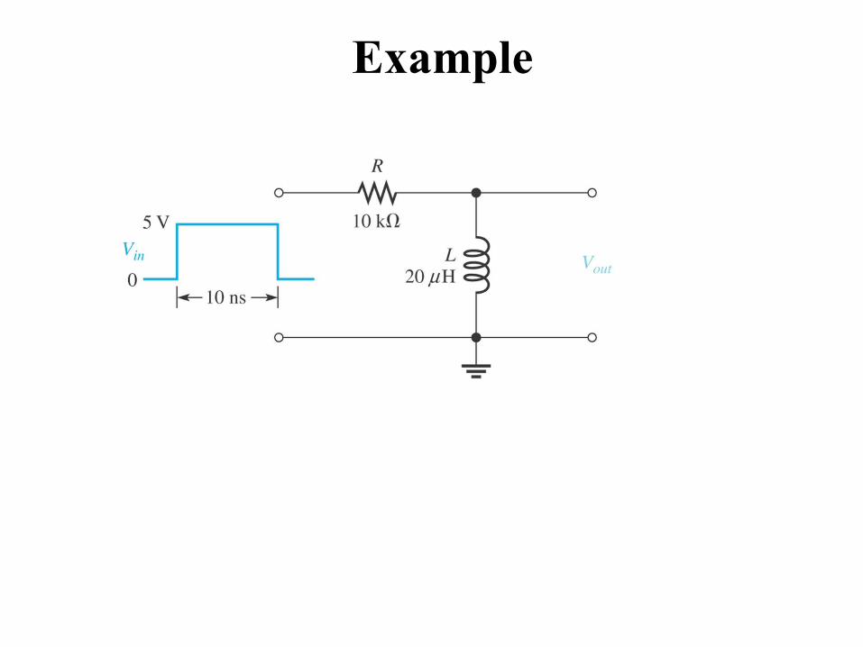
Example
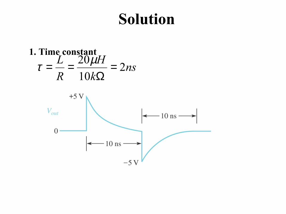
nsk
H
R
L2
10
20 =Ω
== µτ1. Time constant
Solution
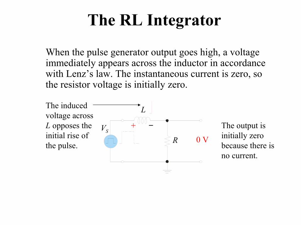
When the pulse generator output goes high, a voltage immediately appears across the inductor in accordance with Lenz’s law. The instantaneous current is zero, so the resistor voltage is initially zero.
The output is initially zero because there is no current.
VS
R
L
+
−
The induced voltage across L opposes the initial rise of the pulse.
0 V
The RL Integrator
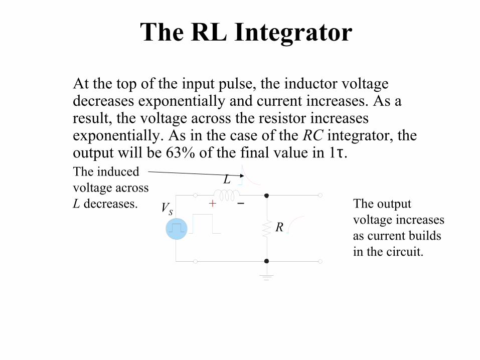
At the top of the input pulse, the inductor voltage decreases exponentially and current increases. As a result, the voltage across the resistor increases exponentially. As in the case of the RC integrator, the output will be 63% of the final value in 1τ.
The output voltage increases as current builds in the circuit.
VS
R
L
+
−
The induced voltage across L decreases.
The RL Integrator
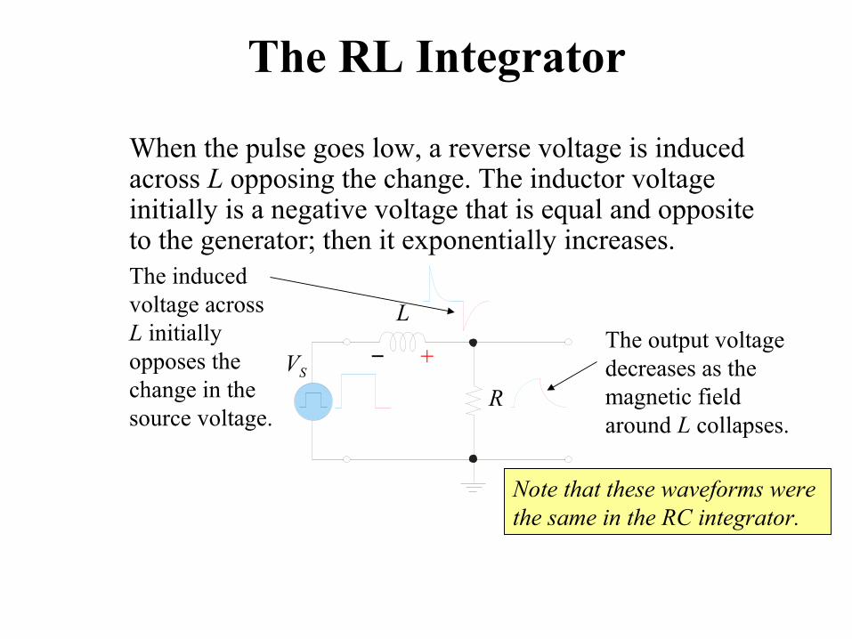
When the pulse goes low, a reverse voltage is induced across L opposing the change. The inductor voltage initially is a negative voltage that is equal and opposite to the generator; then it exponentially increases.
The output voltage decreases as the magnetic field around L collapses.
VS
R
L
+
−
The induced voltage across L initially opposes the change in the source voltage.
Note that these waveforms were the same in the RC integrator.
The RL Integrator
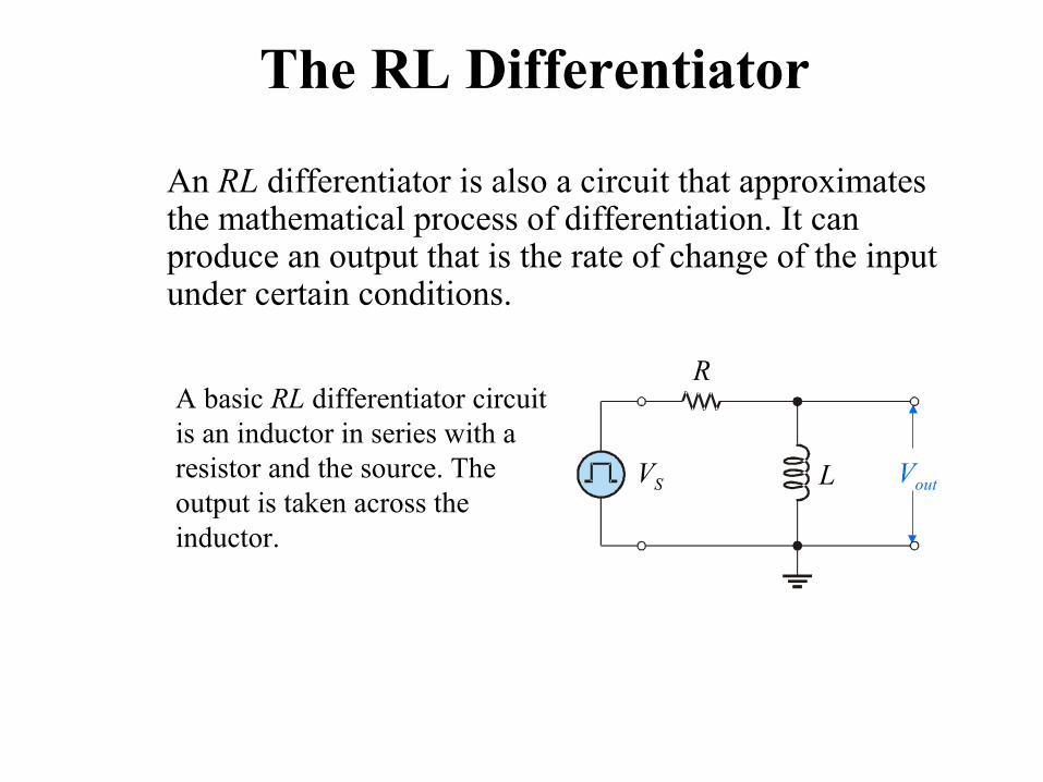
The RL DifferentiatorAn RL differentiator is also a circuit that approximates the mathematical process of differentiation. It can produce an output that is the rate of change of the input under certain conditions.
A basic RL differentiator circuit is an inductor in series with a resistor and the source. The output is taken across the inductor.
VS L
R
Vout
The RL Differentiator
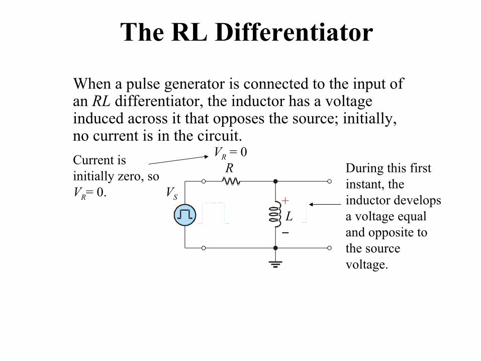
When a pulse generator is connected to the input of an RL differentiator, the inductor has a voltage induced across it that opposes the source; initially, no current is in the circuit.
Current is initially zero, so VR= 0.
During this first instant, the inductor develops a voltage equal and opposite to the source voltage.
VR = 0
VS
L
R
+ −
The RL Differentiator
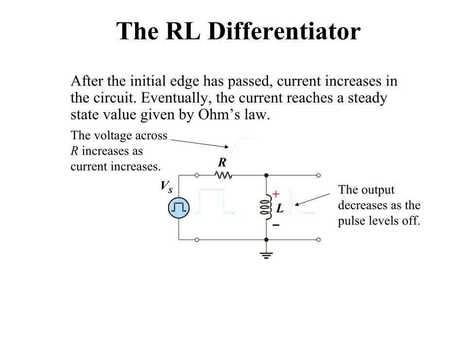
After the initial edge has passed, current increases in the circuit. Eventually, the current reaches a steady state value given by Ohm’s law.The voltage across R increases as current increases.
The output decreases as the pulse levels off.
VS
L
R
+ −
The RL Differentiator
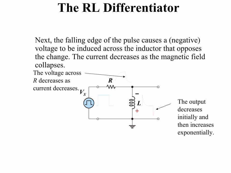
Next, the falling edge of the pulse causes a (negative) voltage to be induced across the inductor that opposes the change. The current decreases as the magnetic field collapses.
The voltage across R decreases as current decreases.
The output decreases initially and then increases exponentially.
VS
L
R
+
−
The RL Differentiator
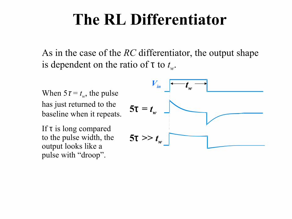
If τ is long compared to the pulse width, the output looks like a pulse with “droop”.
Vin
5τ = tw
5τ >> tw
twWhen 5τ = tw, the pulse has just returned to the baseline when it repeats.
As in the case of the RC differentiator, the output shape is dependent on the ratio of τ to tw.
The RL Differentiator
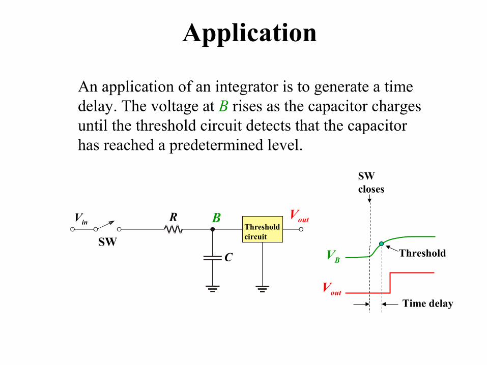
ApplicationAn application of an integrator is to generate a time delay. The voltage at B rises as the capacitor charges until the threshold circuit detects that the capacitor has reached a predetermined level.