15
1 / 14 Appendix 1 Dimensions and Specifications of the RCAR Bumper Barrier System Issue 1 September 2007

8/8/2019 Rcar Bumper Barrier Specification
http://slidepdf.com/reader/full/rcar-bumper-barrier-specification 1/14
1 / 14
Appendix 1
Dimensions and Specificationsof the RCAR Bumper Barrier System
Issue 1
September 2007

8/8/2019 Rcar Bumper Barrier Specification
http://slidepdf.com/reader/full/rcar-bumper-barrier-specification 2/14
2 / 14
INDEX
1.0 INTRODUCTION
2.0 BUMPER BARRIER
3.0 ENERGY ABSORBER
4.0 BUMPER BARRIER ASSEMBLY AND COMPONENTS DRAWINGS

8/8/2019 Rcar Bumper Barrier Specification
http://slidepdf.com/reader/full/rcar-bumper-barrier-specification 3/14
3 / 14
1.0 INTRODUCTION
This document gives the specifications and dimensions for the bumper barrier andenergy absorber test devices used as part of the assessment of damageability in low
speed crashes.
2.0 STEEL BARRIER
2.1 Design and Dimensions
The bumper barrier (Figure 1) is a rigid construction made of steel with a radiusof 3400 mm ± 25 mm across its full width. It is 1500 mm ± 25 mm wide with a flat,100 mm ± 2 mm tall vertical face. The barrier is at least 230 mm deep at its center(without flanges) and should be constructed such that it can be mounted to an
unyielding and immovable crash wall at various heights. (See section 4 for drawings)
Fig. 1: Bumper barrier steel body (example AZT)
R = 3400 mm
8/8/2019 Rcar Bumper Barrier Specification
http://slidepdf.com/reader/full/rcar-bumper-barrier-specification 4/14
4 / 14
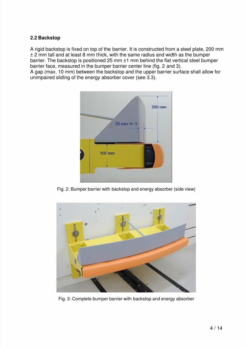
2.2 Backstop
A rigid backstop is fixed on top of the barrier. It is constructed from a steel plate, 200 mm± 2 mm tall and at least 8 mm thick, with the same radius and width as the bumper
barrier. The backstop is positioned 25 mm ±1 mm behind the flat vertical steel bumperbarrier face, measured in the bumper barrier center line (fig. 2 and 3).A gap (max. 10 mm) between the backstop and the upper barrier surface shall allow forunimpaired sliding of the energy absorber cover (see 3.3).
Fig. 2: Bumper barrier with backstop and energy absorber (side view)
Fig. 3: Complete bumper barrier with backstop and energy absorber

8/8/2019 Rcar Bumper Barrier Specification
http://slidepdf.com/reader/full/rcar-bumper-barrier-specification 5/14
5 / 14
3.0 ENERGY ABSORBER
3.1 General
Several different energy absorbers were used in the development of the RCAR bumpersystem including aluminum honeycomb, aluminum egg-crate, and thermo-plasticmaterials. The test results using these various energy absorbers were found to belargely independent of the material. Thus, the energy absorber properties forperpendicular loading and specifications in this document encompass the properties ofall the absorbers used in the test development process. The energy absorber does nothave to be one piece, as long as the dimensions, crush strength, surface hardness andcoefficient of friction are within the specified ranges. One current design 1) consists oftwo components: an energy absorber and a separate cover. If the system consists ofmore than one piece, the entire assembly shall be used when evaluating the crushstrength.
Fig. 4: Energy absorber without cover
3.2 Dimensions
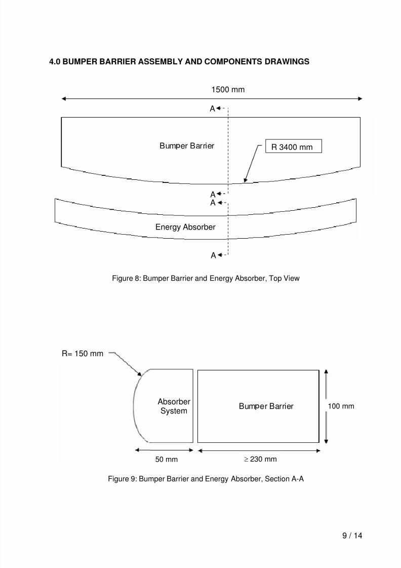
The energy absorber shall be as long as the bumper face, 50 mm deep and is curvedalong its length to a radius of 3400 mm to allow for mounting on the barrier face. Thefront face of the absorber has a 150 mm ± 2 mm top-to-bottom radius, see drawings insection 4.0, figure 9 and 10.
1 made by NetShape International, USA. netshapecorp.com
8/8/2019 Rcar Bumper Barrier Specification
http://slidepdf.com/reader/full/rcar-bumper-barrier-specification 6/14
6 / 14
3.3 Mounting
The energy absorber should be firmly affixed to the underlying bumper barrier facewithout gaps at the interface.
In case the cover of the EA element is wrapped around the metal barrier and fastenedon the top and bottom plane of the barrier, the cover shall be able to slide rearwardswithout influencing the deformation of the EA element. For this purpose a gap betweenthe metal barrier and the backstop is needed. One current design of the cover providesslotted holes to allow unrestricted sliding when the cover is fixed by mushroom typeplastic fasteners. When screws are used they shall not squeeze the cover material. Allfasteners should sit in the far end of the slots to keep the cover in position under slighttension and allow full travel through the slot under impact forces.Other methods of fixing a cover are acceptable as long as they allow for unrestrictedsliding. Horizontal forces needed to slide the cover rearwards should not exceed 50 N.
3.4 Material Properties – Crush Strength
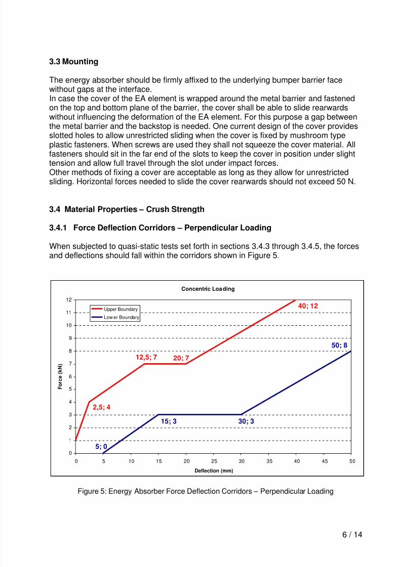
3.4.1 Force Deflection Corridors – Perpendicular Loading
When subjected to quasi-static tests set forth in sections 3.4.3 through 3.4.5, the forcesand deflections should fall within the corridors shown in Figure 5.
Concentric Loading
40; 12
20; 712,5; 7
2,5; 4
5; 0
15; 3
50; 8
30; 3
0
1
2
3
4
5
6
7
8
9
10
11
12
0 5 10 15 20 25 30 35 40 45 50
Deflection (mm)
F o r c e
( k N )
Upper Boundary
Low er Boundary
Figure 5: Energy Absorber Force Deflection Corridors – Perpendicular Loading
8/8/2019 Rcar Bumper Barrier Specification
http://slidepdf.com/reader/full/rcar-bumper-barrier-specification 7/14
7 / 14
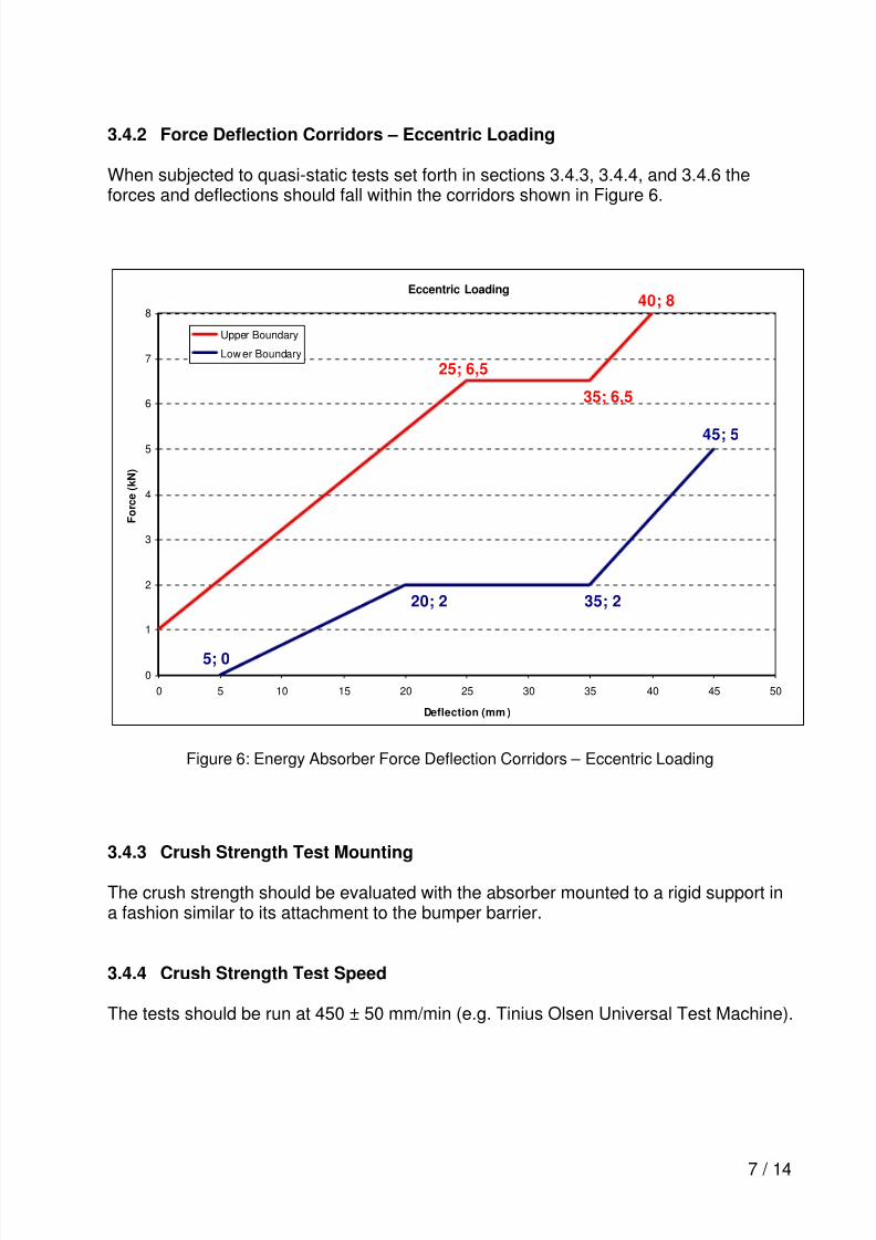
3.4.2 Force Deflection Corridors – Eccentric Loading
When subjected to quasi-static tests set forth in sections 3.4.3, 3.4.4, and 3.4.6 theforces and deflections should fall within the corridors shown in Figure 6.
Eccentric Loading
25; 6,5
35; 6,5
40; 8
35; 2
45; 5
20; 2
5; 00
1
2
3
4
5
6
7
8
0 5 10 15 20 25 30 35 40 45 50
Deflection (mm )
F o r c e ( k N )
Upper Boundary
Low er Boundary
Figure 6: Energy Absorber Force Deflection Corridors – Eccentric Loading
3.4.3 Crush Strength Test Mounting
The crush strength should be evaluated with the absorber mounted to a rigid support ina fashion similar to its attachment to the bumper barrier.
3.4.4 Crush Strength Test Speed
The tests should be run at 450 ± 50 mm/min (e.g. Tinius Olsen Universal Test Machine).

8/8/2019 Rcar Bumper Barrier Specification
http://slidepdf.com/reader/full/rcar-bumper-barrier-specification 8/14
8 / 14
3.4.5 Crush Strength Load Plate – Perpendicular Loading
The load plate should be a rigid rectangular piece of steel 160 mm long and wideenough to cover the entire height of the absorber (i.e. 100 mm).
3.4.6 Crush Strength Load Plate – Eccentric Loading
The load plate should be a rigid rectangular piece of steel 160 mm long and wideenough to cover half of the height of the absorber (i.e. 50 mm). The plate should be ableto rotate along the impacting surface. An example load plate is shown in Figure 7.
Figure 7: An Example of an Eccentric Load Plate
3.4.7 Material Properties – Impact Surface
The impact surface of the energy absorber should have a hardness value between30 and 150 Bhn2 and have a dynamic coefficient of friction between 0.25 and 0.5.3
2Brinell Hardness Number. The Brinell Hardness Number is obtained using a 3000 kg load and a 10 mm
standard ball. The range of 30 to 150 Bhn encompasses materials with hardness values between 25 and100 Shore D and Rockwell Hardness values of zero to 80 Rb.3
The dynamic coefficient of friction is obtained against steel.
8/8/2019 Rcar Bumper Barrier Specification
http://slidepdf.com/reader/full/rcar-bumper-barrier-specification 9/14
9 / 14
4.0 BUMPER BARRIER ASSEMBLY AND COMPONENTS DRAWINGS
Figure 8: Bumper Barrier and Energy Absorber, Top View
Figure 9: Bumper Barrier and Energy Absorber, Section A-A
Bum er Barrier
Energy Absorber
1500 mm
AbsorberSystem
Bum er Barrier
A
A
A
A
R 3400 mm
R= 150 mm
50 mm ≥ 230 mm
100 mm
8/8/2019 Rcar Bumper Barrier Specification
http://slidepdf.com/reader/full/rcar-bumper-barrier-specification 10/14
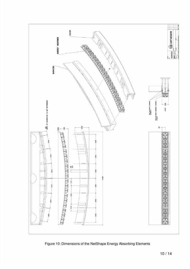
10 / 14
Figure 10: Dimensions of the NetShape Energy Absorbing Elements

8/8/2019 Rcar Bumper Barrier Specification
http://slidepdf.com/reader/full/rcar-bumper-barrier-specification 11/14
11 / 14
Figure 11: Steel Barrier Layout (without backstop) (IIHS)

8/8/2019 Rcar Bumper Barrier Specification
http://slidepdf.com/reader/full/rcar-bumper-barrier-specification 12/14

8/8/2019 Rcar Bumper Barrier Specification
http://slidepdf.com/reader/full/rcar-bumper-barrier-specification 13/14
13 / 14
Figure 13: Backstop Dimensions (US), IIHS Barrier
8/8/2019 Rcar Bumper Barrier Specification
http://slidepdf.com/reader/full/rcar-bumper-barrier-specification 14/14
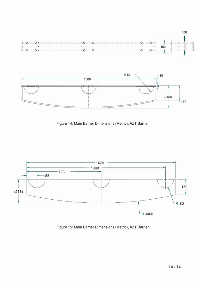
14 / 14
Figure 14: Main Barrier Dimensions (Metric), AZT Barrier
Figure 15: Main Barrier Dimensions (Metric), AZT Barrier


