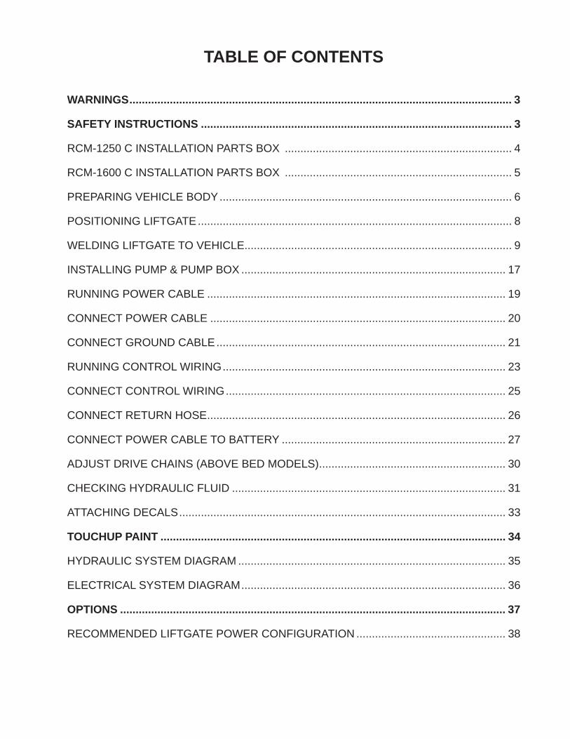
RECOMMENDED LIFTGATE POWER CONFIGURATION ................................................ 38
3
1192
1 Sl
auso
n A
ve.
Sant
a Fe
Spr
ings
, CA
. 90
670
(80
0) 2
27-4
116
FA
X (
888)
771
-771
3
SAFETY INSTRUCTIONS
WARNINGS
SAFETY INSTRUCTIONS
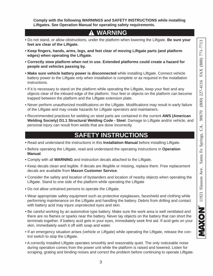
• Comply with all WARNING and instruction decals attached to the Liftgate.
• Keep decals clean and legible. If decals are illegible or missing, replace them. Free replacement decals are available from Maxon Customer Service.
• Consider the safety and location of bystanders and location of nearby objects when operating the Liftgate. Stand to one side of the platform while operating the Liftgate
• Do not stand, or allow obstructions, under the platform when lowering the Liftgate. Be sure your feet are clear of the Liftgate.
• Keep fi ngers, hands, arms, legs, and feet clear of moving Liftgate parts (and platform edges) when operating the Liftgate.
• Wear appropriate safety equipment such as protective eyeglasses, faceshield and clothing while performing maintenance on the Liftgate and handling the battery. Debris from drilling and contact with battery acid may injure unprotected eyes and skin.
• Make sure vehicle battery power is disconnected while installing Liftgate. Connect vehicle battery power to the Liftgate only when installation is complete or as required in the installation instructions.
• Do not allow untrained persons to operate the Liftgate.
• Be careful working by an automotive type battery. Make sure the work area is well ventilated and there are no fl ames or sparks near the battery. Never lay objects on the battery that can short the terminals together. If battery acid gets in your eyes, immediately seek fi rst aid. If acid gets on your skin, immediately wash it off with soap and water.
• If an emergency situation arises (vehicle or Liftgate) while operating the Liftgate, release the con-trol switch to stop the Liftgate.
Comply with the following WARNINGS and SAFETY INSTRUCTIONS while installing Liftgates. See Operation Manual for operating safety requirements.
• Read and understand the instructions in this Installation Manual before installing Liftgate.
• Before operating the Liftgate, read and understand the operating instructions in Operation Manual.
• A correctly installed Liftgate operates smoothly and reasonably quiet. The only noticeable noise during operation comes from the power unit while the platform is raised and lowered. Listen for scraping, grating and binding noises and correct the problem before continuing to operate Liftgate.
• If it is necessary to stand on the platform while operating the Liftgate, keep your feet and any objects clear of the inboard edge of the platform. Your feet or objects on the platform can become trapped between the platform and the Liftgate extension plate.
• Never perform unauthorized modifi cations on the Liftgate. Modifi cations may result in early failure of the Liftgate and may create hazards for Liftgate operators and maintainers.
• Correctly stow platform when not in use. Extended platforms could create a hazard for people and vehicles passing by.
WARNING
• Recommended practices for welding on steel parts are contained in the current AWS (American Welding Society) D1.1 Structural Welding Code - Steel. Damage to Liftgate and/or vehicle, and personal injury can result from welds that are done incorrectly.
!WARNINGS
4
1192
1 Sl
auso
n A
ve.
Sant
a Fe
Spr
ings
, CA
. 90
670
(80
0) 2
27-4
116
FA
X (
888)
771
-771
3
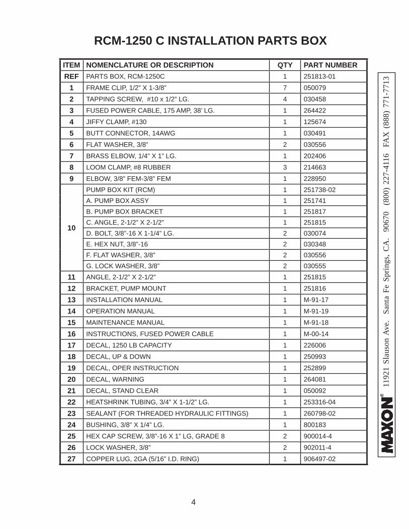
RCM-1250 C INSTALLATION PARTS BOX
ITEM NOMENCLATURE OR DESCRIPTION QTY PART NUMBERREF PARTS BOX, RCM-1250C 1 251813-01
24 HEX CAP SCREW, 3/8”-16 X 1” LG, GRADE 8 2 900014-4
25 LOCK WASHER, 3/8” 2 902011-4
26 COPPER LUG, 2GA (5/16” I.D. RING) 1 906497-02
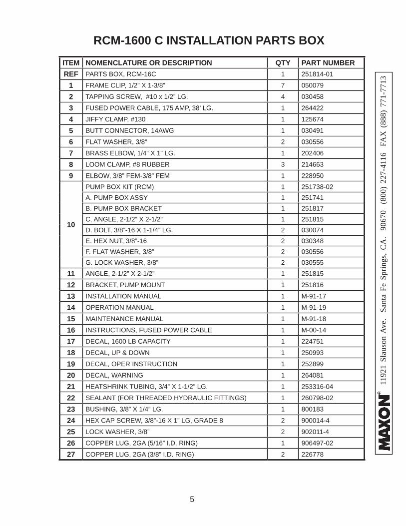
27 COPPER LUG, 2GA (3/8” I.D. RING) 2 226778
6
1192
1 Sl
auso
n A
ve.
Sant
a Fe
Spr
ings
, CA
. 90
670
(80
0) 2
27-4
116
FA
X (
888)
771
-771
3
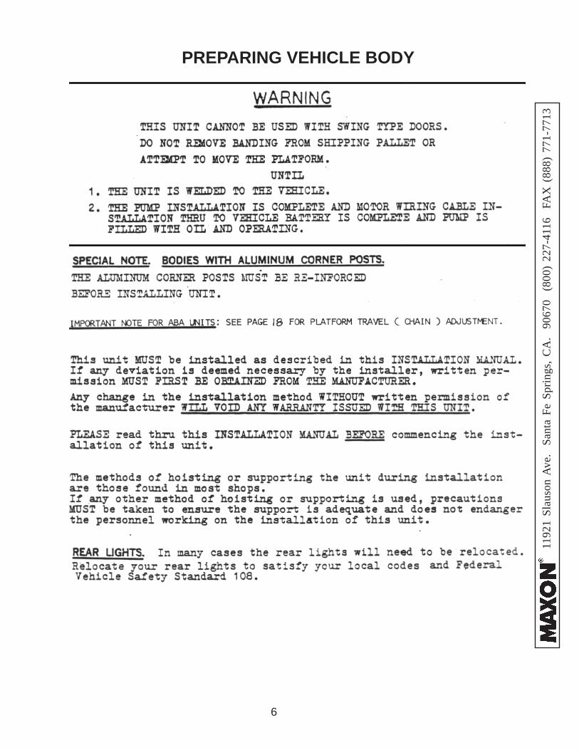
PREPARING VEHICLE BODY
7
1192
1 Sl
auso
n A
ve.
Sant
a Fe
Spr
ings
, CA
. 90
670
(80
0) 2
27-4
116
FA
X (
888)
771
-771
3
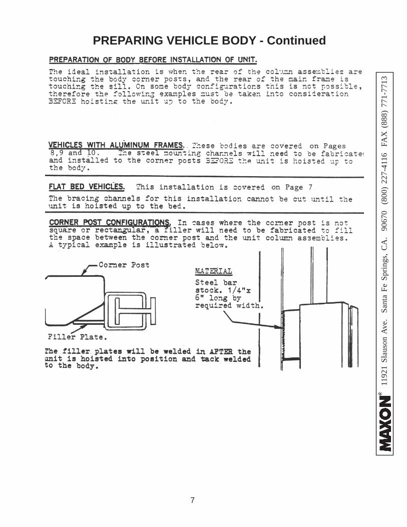
PREPARING VEHICLE BODY - Continued
8
1192
1 Sl
auso
n A
ve.
Sant
a Fe
Spr
ings
, CA
. 90
670
(80
0) 2
27-4
116
FA
X (
888)
771
-771
3
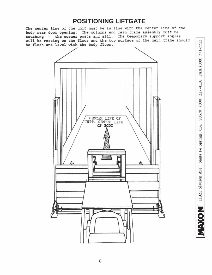
POSITIONING LIFTGATE
9
1192
1 Sl
auso
n A
ve.
Sant
a Fe
Spr
ings
, CA
. 90
670
(80
0) 2
27-4
116
FA
X (
888)
771
-771
3
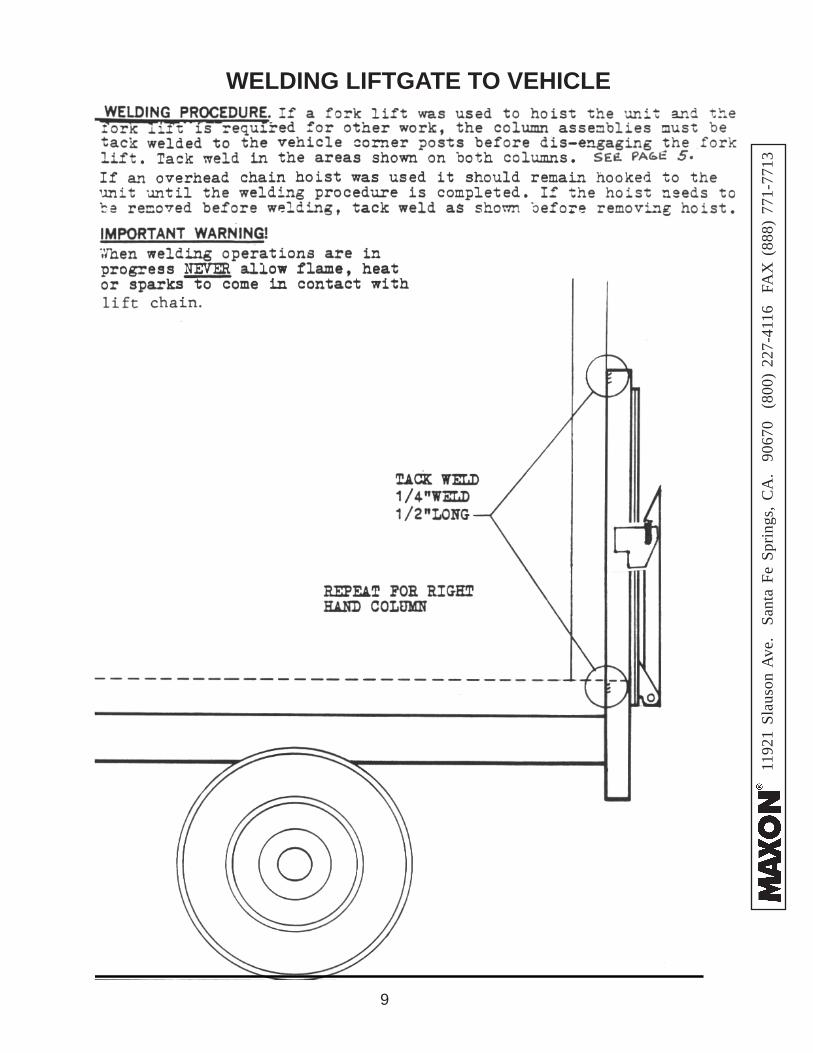
WELDING LIFTGATE TO VEHICLE
10
1192
1 Sl
auso
n A
ve.
Sant
a Fe
Spr
ings
, CA
. 90
670
(80
0) 2
27-4
116
FA
X (
888)
771
-771
3
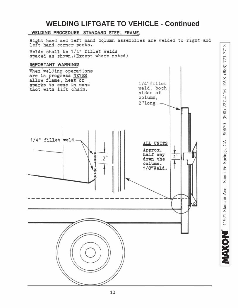
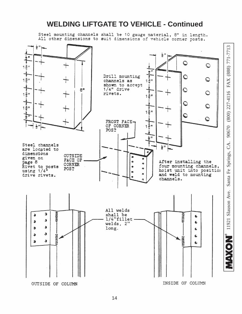
WELDING LIFTGATE TO VEHICLE - Continued
11
1192
1 Sl
auso
n A
ve.
Sant
a Fe
Spr
ings
, CA
. 90
670
(80
0) 2
27-4
116
FA
X (
888)
771
-771
3
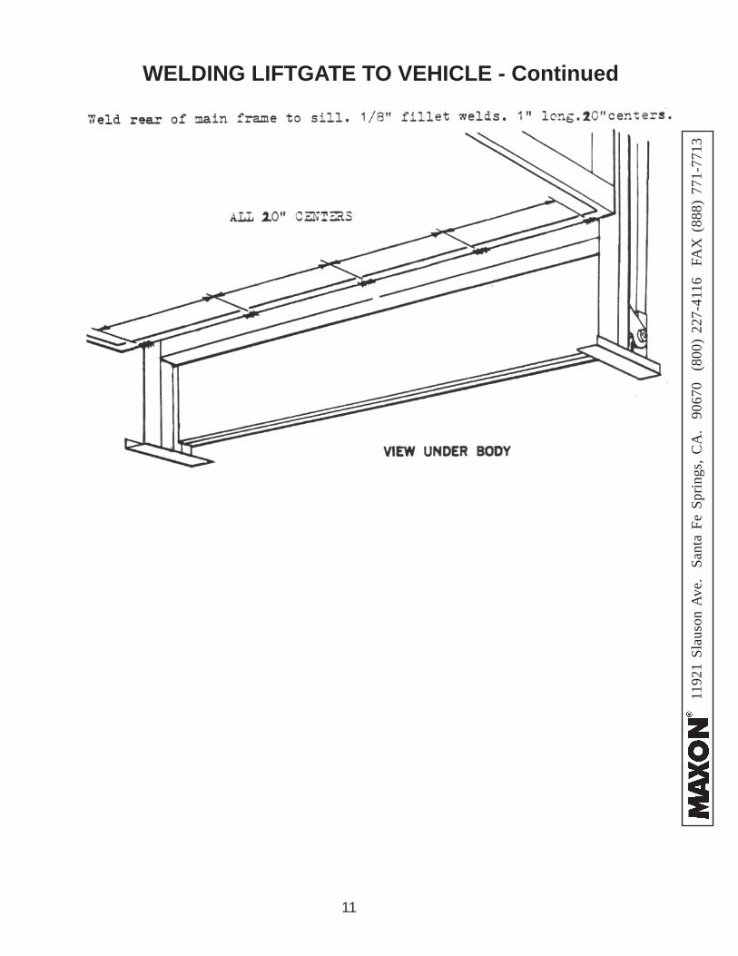
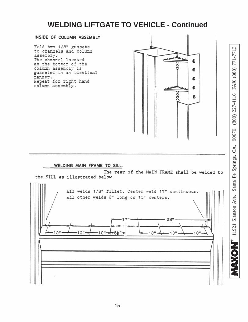
WELDING LIFTGATE TO VEHICLE - Continued
12
1192
1 Sl
auso
n A
ve.
Sant
a Fe
Spr
ings
, CA
. 90
670
(80
0) 2
27-4
116
FA
X (
888)
771
-771
3
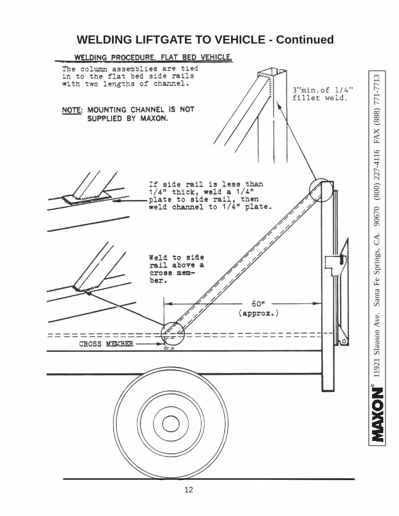
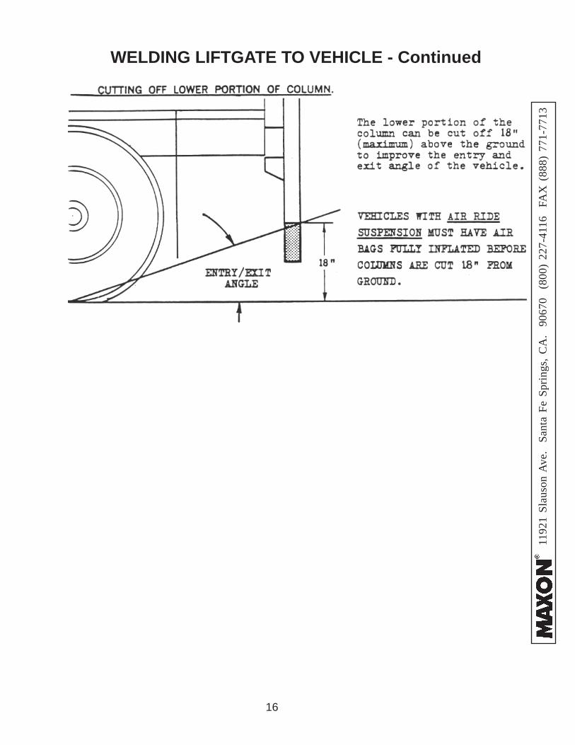
WELDING LIFTGATE TO VEHICLE - Continued
13
1192
1 Sl
auso
n A
ve.
Sant
a Fe
Spr
ings
, CA
. 90
670
(80
0) 2
27-4
116
FA
X (
888)
771
-771
3
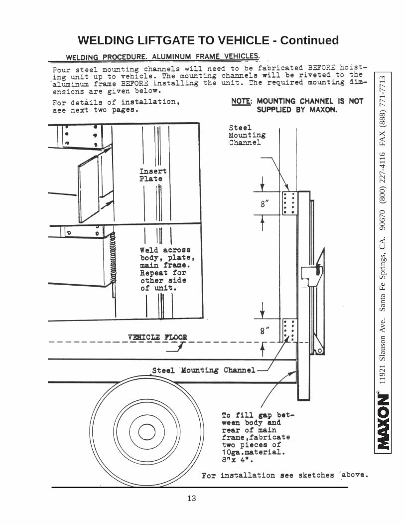
WELDING LIFTGATE TO VEHICLE - Continued
14
1192
1 Sl
auso
n A
ve.
Sant
a Fe
Spr
ings
, CA
. 90
670
(80
0) 2
27-4
116
FA
X (
888)
771
-771
3
WELDING LIFTGATE TO VEHICLE - Continued
15
1192
1 Sl
auso
n A
ve.
Sant
a Fe
Spr
ings
, CA
. 90
670
(80
0) 2
27-4
116
FA
X (
888)
771
-771
3
WELDING LIFTGATE TO VEHICLE - Continued
16
1192
1 Sl
auso
n A
ve.
Sant
a Fe
Spr
ings
, CA
. 90
670
(80
0) 2
27-4
116
FA
X (
888)
771
-771
3
WELDING LIFTGATE TO VEHICLE - Continued
17
1192
1 Sl
auso
n A
ve.
Sant
a Fe
Spr
ings
, CA
. 90
670
(80
0) 2
27-4
116
FA
X (
888)
771
-771
3
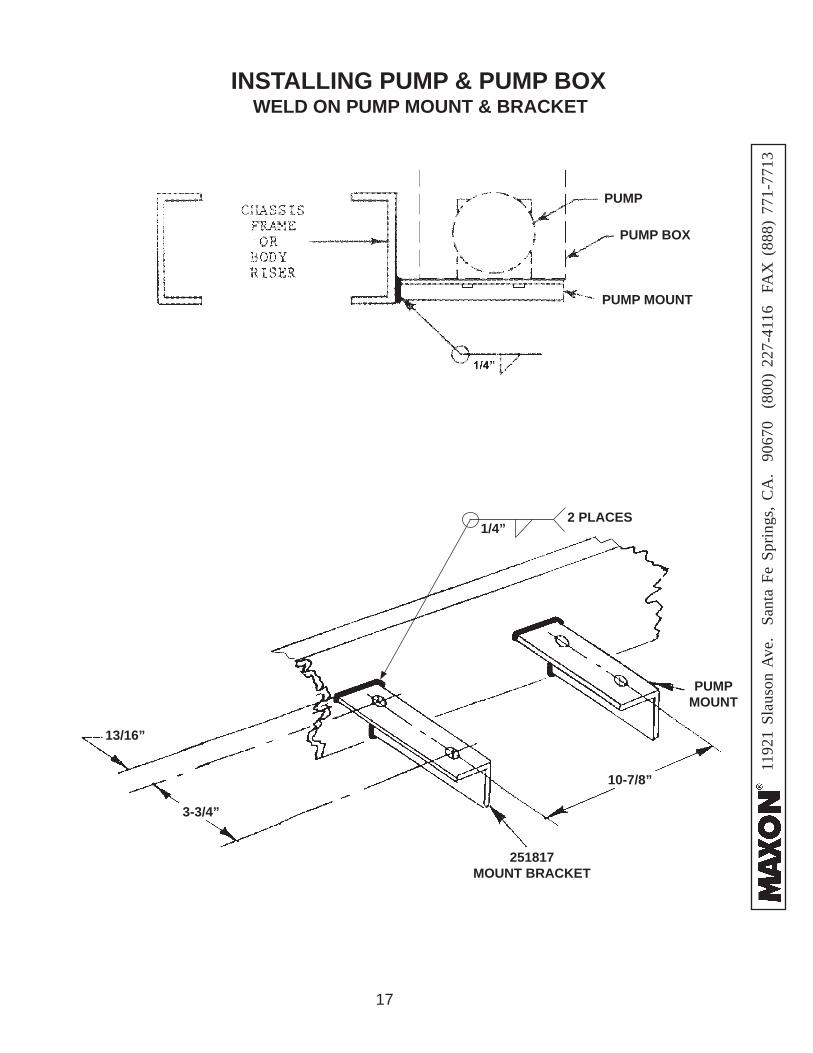
INSTALLING PUMP & PUMP BOX
PUMP BOX
PUMP
13/16”
3-3/4”
10-7/8”
PUMPMOUNT
251817MOUNT BRACKET
1/4”2 PLACES
WELD ON PUMP MOUNT & BRACKET
PUMP MOUNT
18
1192
1 Sl
auso
n A
ve.
Sant
a Fe
Spr
ings
, CA
. 90
670
(80
0) 2
27-4
116
FA
X (
888)
771
-771
3
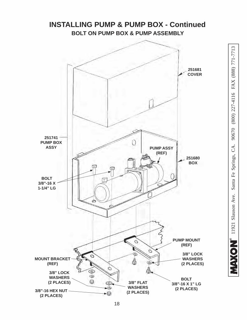
INSTALLING PUMP & PUMP BOX - Continued
251741PUMP BOX
ASSY
251681COVER
251680BOX
PUMP ASSY (REF)
BOLT ON PUMP BOX & PUMP ASSEMBLY
BOLT 3/8”-16 X 1-1/4” LG
3/8” FLAT WASHERS (2 PLACES)
3/8” LOCK WASHERS (2 PLACES)
3/8”-16 HEX NUT(2 PLACES)
BOLT 3/8”-16 X 1” LG
(2 PLACES)
3/8” LOCK WASHERS (2 PLACES)
MOUNT BRACKET(REF)
PUMP MOUNT(REF)
19
1192
1 Sl
auso
n A
ve.
Sant
a Fe
Spr
ings
, CA
. 90
670
(80
0) 2
27-4
116
FA
X (
888)
771
-771
3
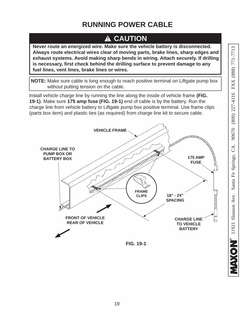
RUNNING POWER CABLE
Never route an energized wire. Make sure the vehicle battery is disconnected. Always route electrical wires clear of moving parts, brake lines, sharp edges and exhaust systems. Avoid making sharp bends in wiring. Attach securely. If drilling is necessary, fi rst check behind the drilling surface to prevent damage to any fuel lines, vent lines, brake lines or wires.
CAUTION!
FIG. 19-1
VEHICLE FRAME
18” - 24”SPACING
CHARGE LINE TO PUMP BOX OR BATTERY BOX
FRONT OF VEHICLEREAR OF VEHICLE
CHARGE LINE TO VEHICLE
BATTERY
FRAME CLIPS
175 AMP FUSE
Install vehicle charge line by running the line along the inside of vehicle frame (FIG. 19-1). Make sure 175 amp fuse (FIG. 19-1) end of cable is by the battery. Run the charge line from vehicle battery to Liftgate pump box positive terminal. Use frame clips (parts box item) and plastic ties (as required) from charge line kit to secure cable.
NOTE: Make sure cable is long enough to reach positive terminal on Liftgate pump box without putting tension on the cable.
20
1192
1 Sl
auso
n A
ve.
Sant
a Fe
Spr
ings
, CA
. 90
670
(80
0) 2
27-4
116
FA
X (
888)
771
-771
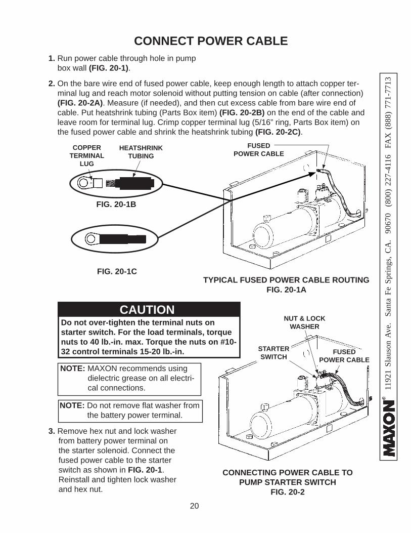
32. On the bare wire end of fused power cable, keep enough length to attach copper ter-minal lug and reach motor solenoid without putting tension on cable (after connection) (FIG. 20-2A). Measure (if needed), and then cut excess cable from bare wire end of cable. Put heatshrink tubing (Parts Box item) (FIG. 20-2B) on the end of the cable and leave room for terminal lug. Crimp copper terminal lug (5/16” ring, Parts Box item) on the fused power cable and shrink the heatshrink tubing (FIG. 20-2C).
CONNECT POWER CABLE
TYPICAL FUSED POWER CABLE ROUTINGFIG. 20-1A
FIG. 20-1B
COPPER TERMINAL
LUG
HEATSHRINK TUBING
FIG. 20-1C
FUSEDPOWER CABLE
CONNECTING POWER CABLE TO PUMP STARTER SWITCH
FIG. 20-2
FUSEDPOWER CABLE
3. Remove hex nut and lock washer from battery power terminal on the starter solenoid. Connect the fused power cable to the starter switch as shown in FIG. 20-1. Reinstall and tighten lock washer and hex nut.
NOTE: MAXON recommends using dielectric grease on all electri-cal connections.
Do not over-tighten the terminal nuts on starter switch. For the load terminals, torque nuts to 40 lb.-in. max. Torque the nuts on #10-32 control terminals 15-20 lb.-in.
CAUTION
NOTE: Do not remove fl at washer from the battery power terminal.
STARTERSWITCH
NUT & LOCK WASHER
1. Run power cable through hole in pump box wall (FIG. 20-1).
21
1192
1 Sl
auso
n A
ve.
Sant
a Fe
Spr
ings
, CA
. 90
670
(80
0) 2
27-4
116
FA
X (
888)
771
-771
3
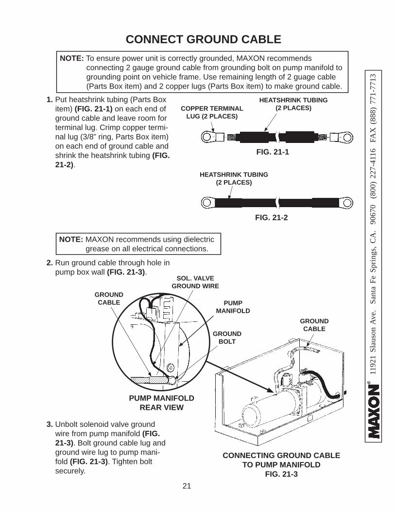
CONNECT GROUND CABLENOTE: To ensure power unit is correctly grounded, MAXON recommends connecting 2 gauge ground cable from grounding bolt on pump manifold to
grounding point on vehicle frame. Use remaining length of 2 guage cable (Parts Box item) and 2 copper lugs (Parts Box item) to make ground cable.
1. Put heatshrink tubing (Parts Box item) (FIG. 21-1) on each end of ground cable and leave room for terminal lug. Crimp copper termi-nal lug (3/8” ring, Parts Box item) on each end of ground cable and shrink the heatshrink tubing (FIG. 21-2).
FIG. 21-1
COPPER TERMINAL LUG (2 PLACES)
HEATSHRINK TUBING (2 PLACES)
FIG. 21-2
HEATSHRINK TUBING (2 PLACES)
3. Unbolt solenoid valve ground wire from pump manifold (FIG. 21-3). Bolt ground cable lug and ground wire lug to pump mani-fold (FIG. 21-3). Tighten bolt securely.
NOTE: MAXON recommends using dielectric grease on all electrical connections.
CONNECTING GROUND CABLE TO PUMP MANIFOLD
FIG. 21-3
GROUNDBOLT
2. Run ground cable through hole in pump box wall (FIG. 21-3).
GROUNDCABLE
SOL. VALVE GROUND WIRE
PUMP MANIFOLD REAR VIEW
PUMP MANIFOLD
GROUNDCABLE
22
1192
1 Sl
auso
n A
ve.
Sant
a Fe
Spr
ings
, CA
. 90
670
(80
0) 2
27-4
116
FA
X (
888)
771
-771
3
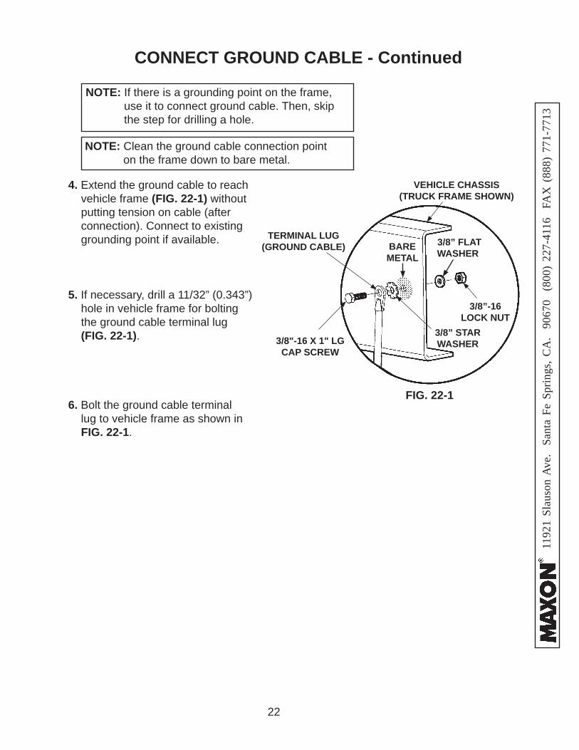
FIG. 22-1
TERMINAL LUG (GROUND CABLE)
3/8” STARWASHER
3/8” FLAT WASHER
3/8”-16LOCK NUT
VEHICLE CHASSIS(TRUCK FRAME SHOWN)
4. Extend the ground cable to reach vehicle frame (FIG. 22-1) without putting tension on cable (after connection). Connect to existing grounding point if available.
3/8"-16 X 1" LG CAP SCREW
6. Bolt the ground cable terminal lug to vehicle frame as shown in FIG. 22-1.
BARE METAL
5. If necessary, drill a 11/32” (0.343”) hole in vehicle frame for bolting the ground cable terminal lug (FIG. 22-1).
NOTE: If there is a grounding point on the frame, use it to connect ground cable. Then, skip the step for drilling a hole.
NOTE: Clean the ground cable connection point on the frame down to bare metal.
CONNECT GROUND CABLE - Continued
23
1192
1 Sl
auso
n A
ve.
Sant
a Fe
Spr
ings
, CA
. 90
670
(80
0) 2
27-4
116
FA
X (
888)
771
-771
3
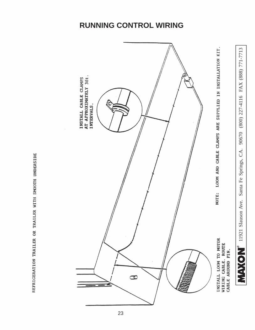
RUNNING CONTROL WIRING
24
1192
1 Sl
auso
n A
ve.
Sant
a Fe
Spr
ings
, CA
. 90
670
(80
0) 2
27-4
116
FA
X (
888)
771
-771
3
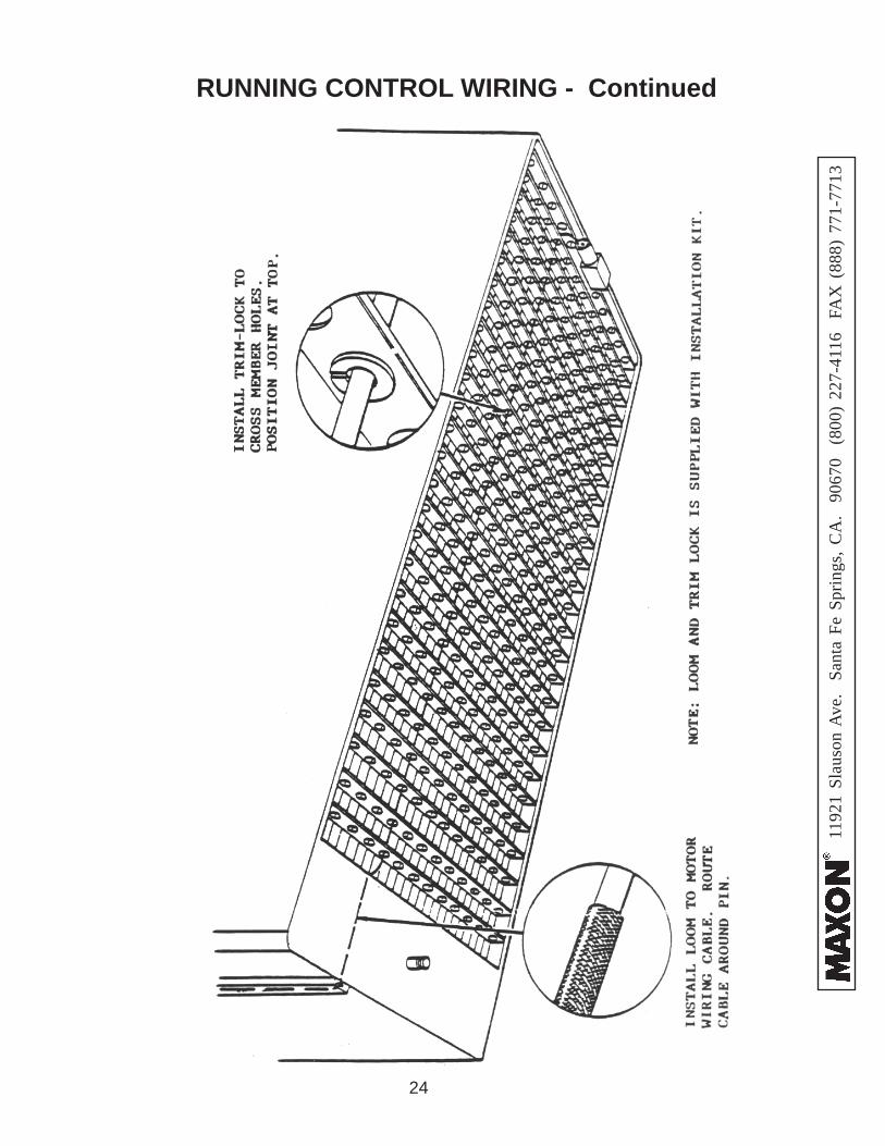
RUNNING CONTROL WIRING - Continued
25
1192
1 Sl
auso
n A
ve.
Sant
a Fe
Spr
ings
, CA
. 90
670
(80
0) 2
27-4
116
FA
X (
888)
771
-771
3
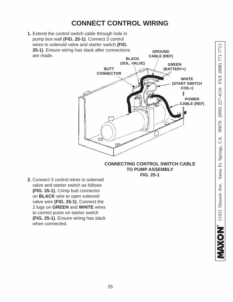
CONNECT CONTROL WIRING
CONNECTING CONTROL SWITCH CABLE TO PUMP ASSEMBLY
FIG. 25-1
BLACK(SOL. VALVE) GREEN
(BATTERY+)
WHITE(START SWITCH
COIL+)
BUTT CONNECTOR
1. Extend the control switch cable through hole in pump box wall (FIG. 25-1). Connect 3 control wires to solenoid valve and starter switch (FIG. 25-1). Ensure wiring has slack after connections are made.
2. Connect 3 control wires to solenoid valve and starter switch as follows (FIG. 25-1). Crimp butt connector on BLACK wire to open solenoid valve wire (FIG. 25-1). Connect the 2 lugs on GREEN and WHITE wires to correct posts on starter switch (FIG. 25-1). Ensure wiring has slack when connected.
POWER CABLE (REF)
GROUND CABLE (REF)
26
1192
1 Sl
auso
n A
ve.
Sant
a Fe
Spr
ings
, CA
. 90
670
(80
0) 2
27-4
116
FA
X (
888)
771
-771
3
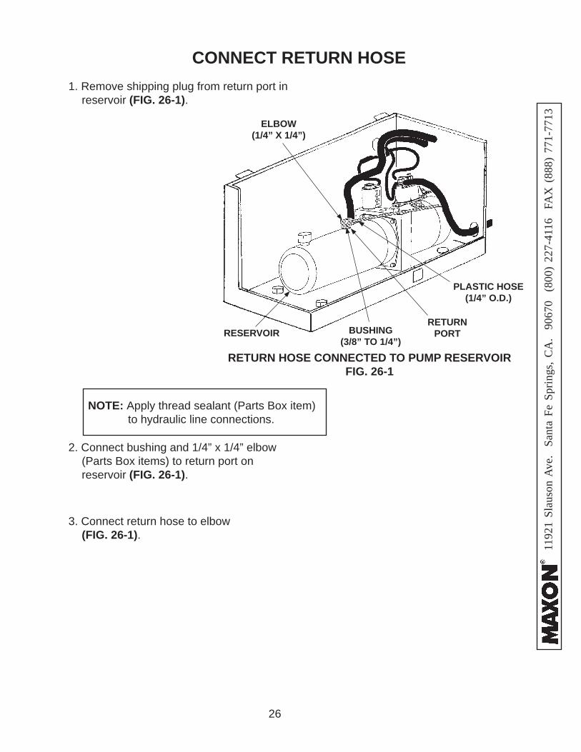
CONNECT RETURN HOSE
2. Connect bushing and 1/4” x 1/4” elbow (Parts Box items) to return port on reservoir (FIG. 26-1).
RETURN HOSE CONNECTED TO PUMP RESERVOIRFIG. 26-1
BUSHING(3/8” TO 1/4”)
PLASTIC HOSE(1/4” O.D.)
ELBOW(1/4” X 1/4”)
RESERVOIR
3. Connect return hose to elbow (FIG. 26-1).
NOTE: Apply thread sealant (Parts Box item) to hydraulic line connections.
1. Remove shipping plug from return port in reservoir (FIG. 26-1).
RETURN PORT
27
1192
1 Sl
auso
n A
ve.
Sant
a Fe
Spr
ings
, CA
. 90
670
(80
0) 2
27-4
116
FA
X (
888)
771
-771
3
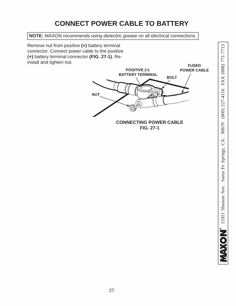
CONNECT POWER CABLE TO BATTERY
Remove nut from positive (+) battery terminal connector. Connect power cable to the positive (+) battery terminal connector (FIG. 27-1). Re-install and tighten nut.
CONNECTING POWER CABLEFIG. 27-1
POSITIVE (+) BATTERY TERMINAL
FUSED POWER CABLE
BOLT
NUT
NOTE: MAXON recommends using dielectric grease on all electrical connections.
28
1192
1 Sl
auso
n A
ve.
Sant
a Fe
Spr
ings
, CA
. 90
670
(80
0) 2
27-4
116
FA
X (
888)
771
-771
3
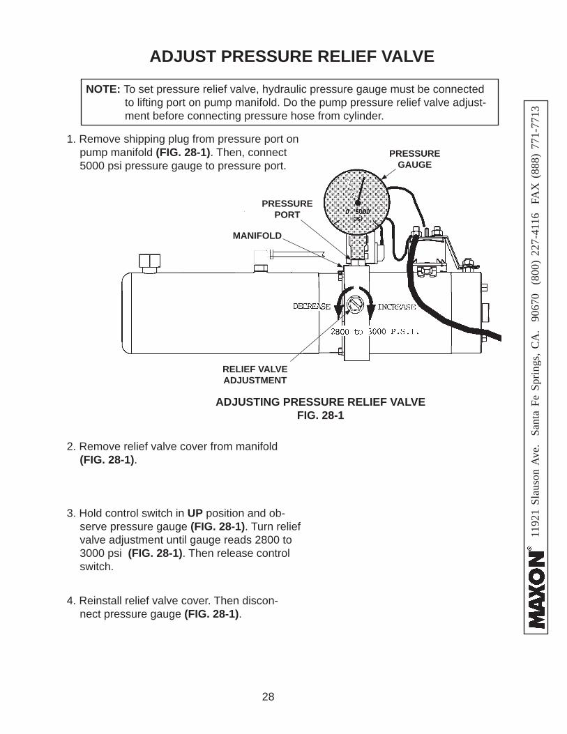
ADJUST PRESSURE RELIEF VALVE
NOTE: To set pressure relief valve, hydraulic pressure gauge must be connected to lifting port on pump manifold. Do the pump pressure relief valve adjust-ment before connecting pressure hose from cylinder.
1. Remove shipping plug from pressure port on pump manifold (FIG. 28-1). Then, connect 5000 psi pressure gauge to pressure port.
3. Hold control switch in UP position and ob-serve pressure gauge (FIG. 28-1). Turn relief valve adjustment until gauge reads 2800 to 3000 psi (FIG. 28-1). Then release control switch.
2. Remove relief valve cover from manifold (FIG. 28-1).
1. Connect pipe nipple and swivel elbow (Parts Box items) to pressure port on pump manifold (FIG. 29-1).
PRESSURE HOSE CONNECTED TO PUMP MANIFOLD FIG. 29-1
PRESSUREPORT
MANIFOLD
ELBOW
PRESSURE HOSE
2” LG PIPE NIPPLE
2. Connect pressure hose to swivel end of pipe nipple (FIG. 29-1).
SWIVEL
NOTE: Apply thread sealant (Parts Box item) to hydraulic line connections.
30
1192
1 Sl
auso
n A
ve.
Sant
a Fe
Spr
ings
, CA
. 90
670
(80
0) 2
27-4
116
FA
X (
888)
771
-771
3
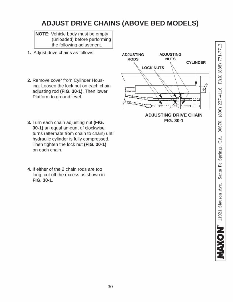
ADJUSTING DRIVE CHAIN FIG. 30-1
1. Adjust drive chains as follows.
NOTE: Vehicle body must be empty (unloaded) before performing the following adjustment.
ADJUST DRIVE CHAINS (ABOVE BED MODELS)
2. Remove cover from Cylinder Hous-ing. Loosen the lock nut on each chain adjusting rod (FIG. 30-1). Then lower Platform to ground level.
3. Turn each chain adjusting nut (FIG. 30-1) an equal amount of clockwise turns (alternate from chain to chain) until hydraulic cylinder is fully compressed. Then tighten the lock nut (FIG. 30-1) on each chain.
4. If either of the 2 chain rods are too long, cut off the excess as shown in FIG. 30-1.
CYLINDERLOCK NUTS
ADJUSTING NUTS
ADJUSTING RODS
31
1192
1 Sl
auso
n A
ve.
Sant
a Fe
Spr
ings
, CA
. 90
670
(80
0) 2
27-4
116
FA
X (
888)
771
-771
3
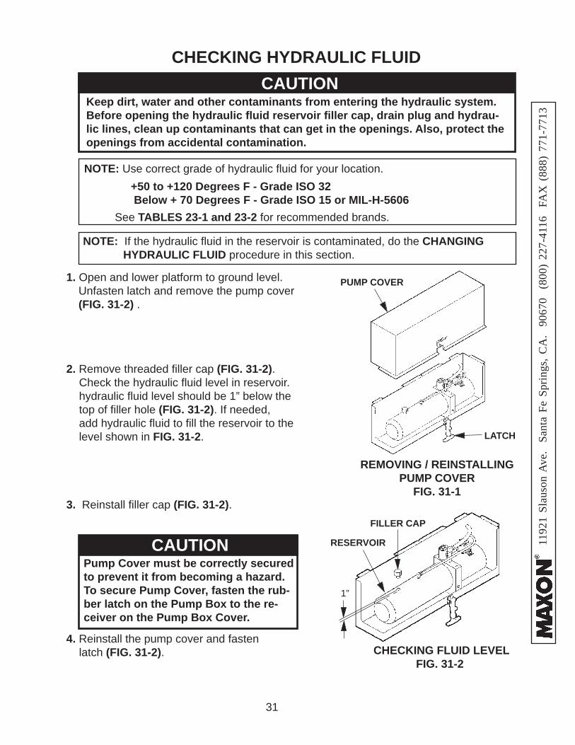
CHECKING HYDRAULIC FLUID
NOTE: If the hydraulic fl uid in the reservoir is contaminated, do the CHANGING HYDRAULIC FLUID procedure in this section.
CAUTIONKeep dirt, water and other contaminants from entering the hydraulic system. Before opening the hydraulic fl uid reservoir fi ller cap, drain plug and hydrau-lic lines, clean up contaminants that can get in the openings. Also, protect the openings from accidental contamination.
+50 to +120 Degrees F - Grade ISO 32 Below + 70 Degrees F - Grade ISO 15 or MIL-H-5606
NOTE: Use correct grade of hydraulic fl uid for your location.
See TABLES 23-1 and 23-2 for recommended brands.
1. Open and lower platform to ground level. Unfasten latch and remove the pump cover (FIG. 31-2) .
CHECKING FLUID LEVELFIG. 31-2
3. Reinstall fi ller cap (FIG. 31-2).
2. Remove threaded fi ller cap (FIG. 31-2). Check the hydraulic fl uid level in reservoir. hydraulic fl uid level should be 1” below the top of fi ller hole (FIG. 31-2). If needed, add hydraulic fl uid to fi ll the reservoir to the level shown in FIG. 31-2.
FILLER CAP
RESERVOIR
4. Reinstall the pump cover and fasten latch (FIG. 31-2).
1”
CAUTIONPump Cover must be correctly secured to prevent it from becoming a hazard. To secure Pump Cover, fasten the rub-ber latch on the Pump Box to the re-ceiver on the Pump Box Cover.
LATCH
PUMP COVER
REMOVING / REINSTALLINGPUMP COVER
FIG. 31-1
32
1192
1 Sl
auso
n A
ve.
Sant
a Fe
Spr
ings
, CA
. 90
670
(80
0) 2
27-4
116
FA
X (
888)
771
-771
3
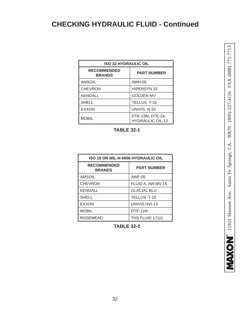
TABLE 32-1
TABLE 32-2
ISO 32 HYDRAULIC OILRECOMMENDED
BRANDS PART NUMBER
AMSOIL AWH-05
CHEVRON HIPERSYN 32
KENDALL GOLDEN MV
SHELL TELLUS T-32
EXXON UNIVIS N-32
MOBIL DTE-13M, DTE-24,HYDRAULIC OIL-13
ISO 15 OR MIL-H-5606 HYDRAULIC OIL
RECOMMENDED BRANDS PART NUMBER
AMSOIL AWF-05
CHEVRON FLUID A, AW-MV-15
KENDALL GLACIAL BLU
SHELL TELLUS T-15
EXXON UNIVIS HVI-13
MOBIL DTE-11M
ROSEMEAD THS FLUID 17111
CHECKING HYDRAULIC FLUID - Continued
33
1192
1 Sl
auso
n A
ve.
Sant
a Fe
Spr
ings
, CA
. 90
670
(80
0) 2
27-4
116
FA
X (
888)
771
-771
3
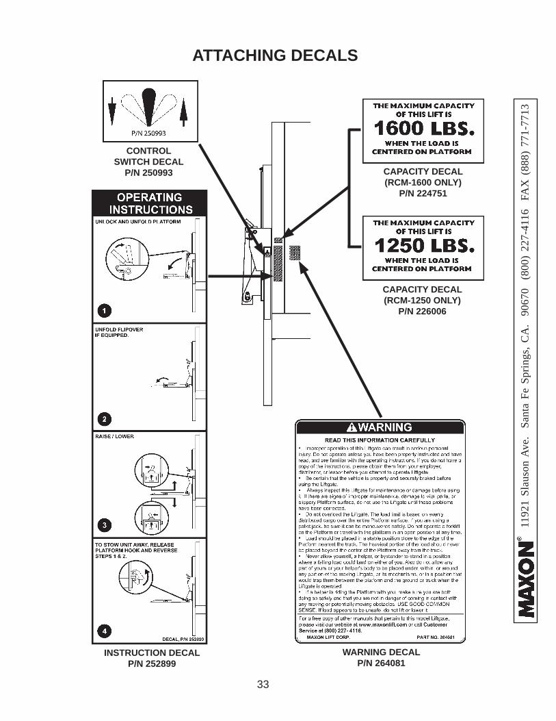
INSTRUCTION DECALP/N 252899
WARNING DECALP/N 264081
CAPACITY DECAL (RCM-1600 ONLY)
P/N 224751
CONTROLSWITCH DECAL
P/N 250993
ATTACHING DECALS
CAPACITY DECAL (RCM-1250 ONLY)
P/N 226006
34
1192
1 Sl
auso
n A
ve.
Sant
a Fe
Spr
ings
, CA
. 90
670
(80
0) 2
27-4
116
FA
X (
888)
771
-771
3Damaged cylinder seals and contaminated hydraulic fl uid can result from paint-ing the polished portion of the cylinder rod. To prevent damage, protect the exposed polished portion of the cylinder rod while painting.
CAUTION
TOUCHUP PAINT
If bare metal or primer is exposed on the painted portions of the Liftgate, touch up the paint. To maintain the protection provided by the original paint system, MAXON recom-mends aluminum primer touchup paint kit, P/N 908134-01.
35
1192
1 Sl
auso
n A
ve.
Sant
a Fe
Spr
ings
, CA
. 90
670
(80
0) 2
27-4
116
FA
X (
888)
771
-771
3
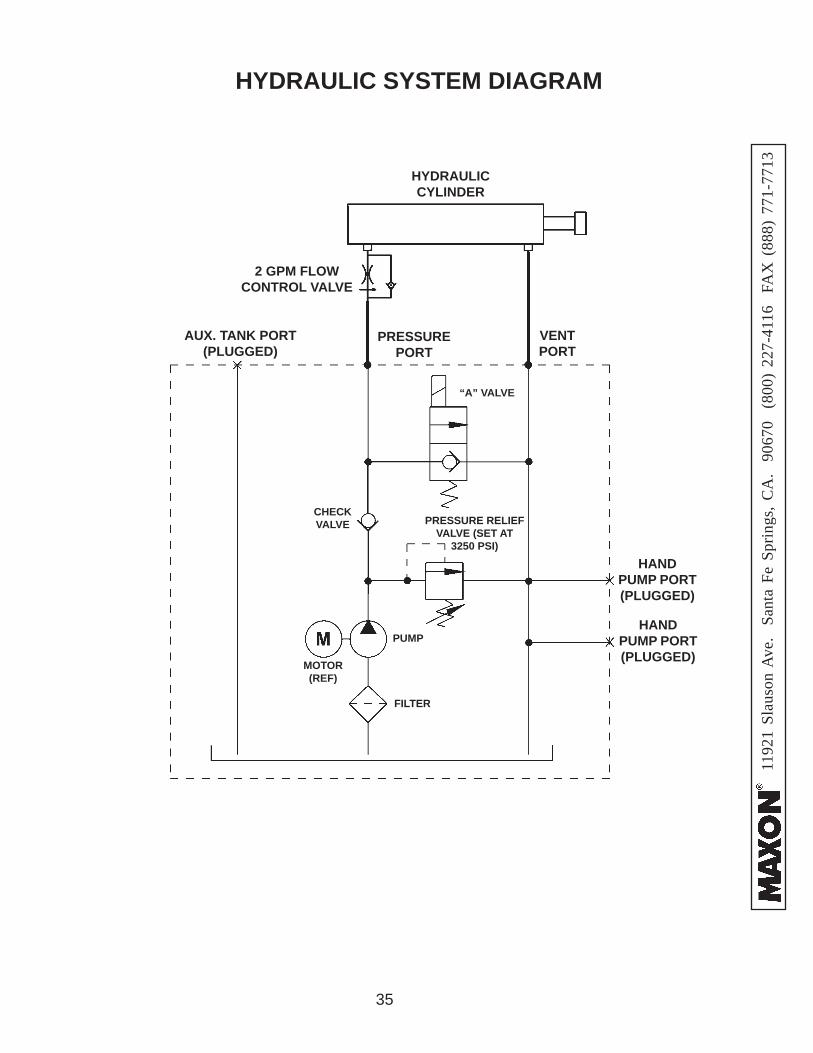
HYDRAULIC SYSTEM DIAGRAM
HYDRAULIC CYLINDER
“A” VALVE
PRESSURE RELIEF VALVE (SET AT
3250 PSI)
CHECKVALVE
MOTOR(REF)
PUMP
FILTER
HAND PUMP PORT (PLUGGED)
HAND PUMP PORT (PLUGGED)
AUX. TANK PORT (PLUGGED)
PRESSUREPORT
VENTPORT
2 GPM FLOW CONTROL VALVE
36
1192
1 Sl
auso
n A
ve.
Sant
a Fe
Spr
ings
, CA
. 90
670
(80
0) 2
27-4
116
FA
X (
888)
771
-771
3
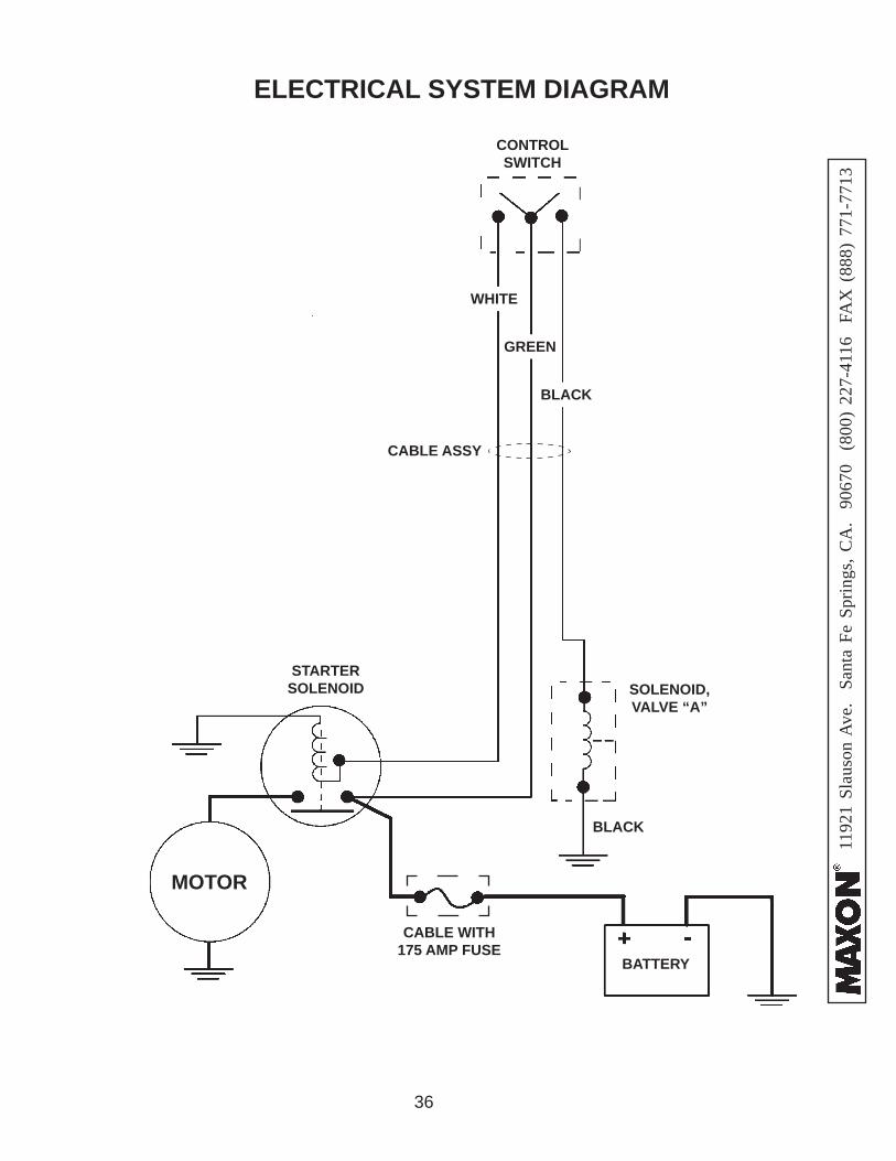
ELECTRICAL SYSTEM DIAGRAM
BLACK
GREEN
MOTOR
BATTERY
CONTROL SWITCH
STARTER SOLENOID SOLENOID,
VALVE “A”
CABLE WITH175 AMP FUSE
WHITE
BLACK
CABLE ASSY
37
1192
1 Sl
auso
n A
ve.
Sant
a Fe
Spr
ings
, CA
. 90
670
(80
0) 2
27-4
116
FA
X (
888)
771
-771
3
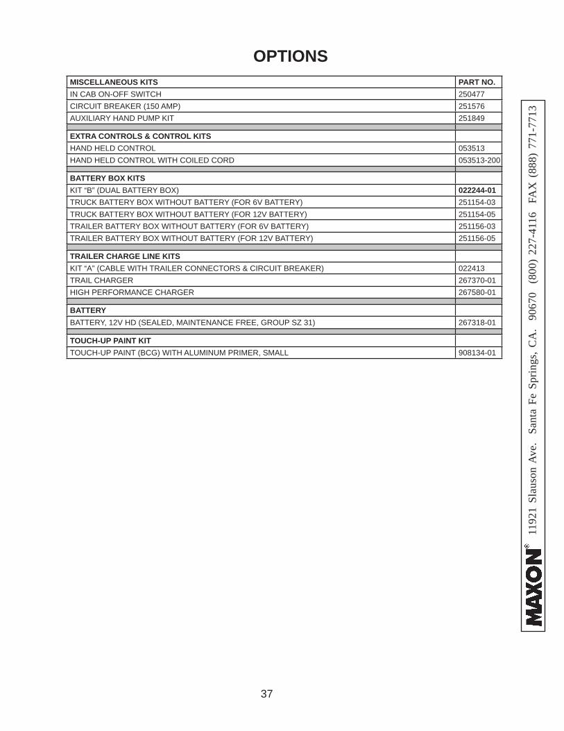
OPTIONSMISCELLANEOUS KITS PART NO.IN CAB ON-OFF SWITCH 250477CIRCUIT BREAKER (150 AMP) 251576AUXILIARY HAND PUMP KIT 251849
EXTRA CONTROLS & CONTROL KITSHAND HELD CONTROL 053513HAND HELD CONTROL WITH COILED CORD 053513-200
BATTERY BOX KITSKIT “B” (DUAL BATTERY BOX) 022244-01TRUCK BATTERY BOX WITHOUT BATTERY (FOR 6V BATTERY) 251154-03TRUCK BATTERY BOX WITHOUT BATTERY (FOR 12V BATTERY) 251154-05TRAILER BATTERY BOX WITHOUT BATTERY (FOR 6V BATTERY) 251156-03TRAILER BATTERY BOX WITHOUT BATTERY (FOR 12V BATTERY) 251156-05
TRAILER CHARGE LINE KITSKIT “A” (CABLE WITH TRAILER CONNECTORS & CIRCUIT BREAKER) 022413TRAIL CHARGER 267370-01HIGH PERFORMANCE CHARGER 267580-01
BATTERYBATTERY, 12V HD (SEALED, MAINTENANCE FREE, GROUP SZ 31) 267318-01
TOUCH-UP PAINT KITTOUCH-UP PAINT (BCG) WITH ALUMINUM PRIMER, SMALL 908134-01
38
1192
1 Sl
auso
n A
ve.
Sant
a Fe
Spr
ings
, CA
. 90
670
(80
0) 2
27-4
116
FA
X (
888)
771
-771
3
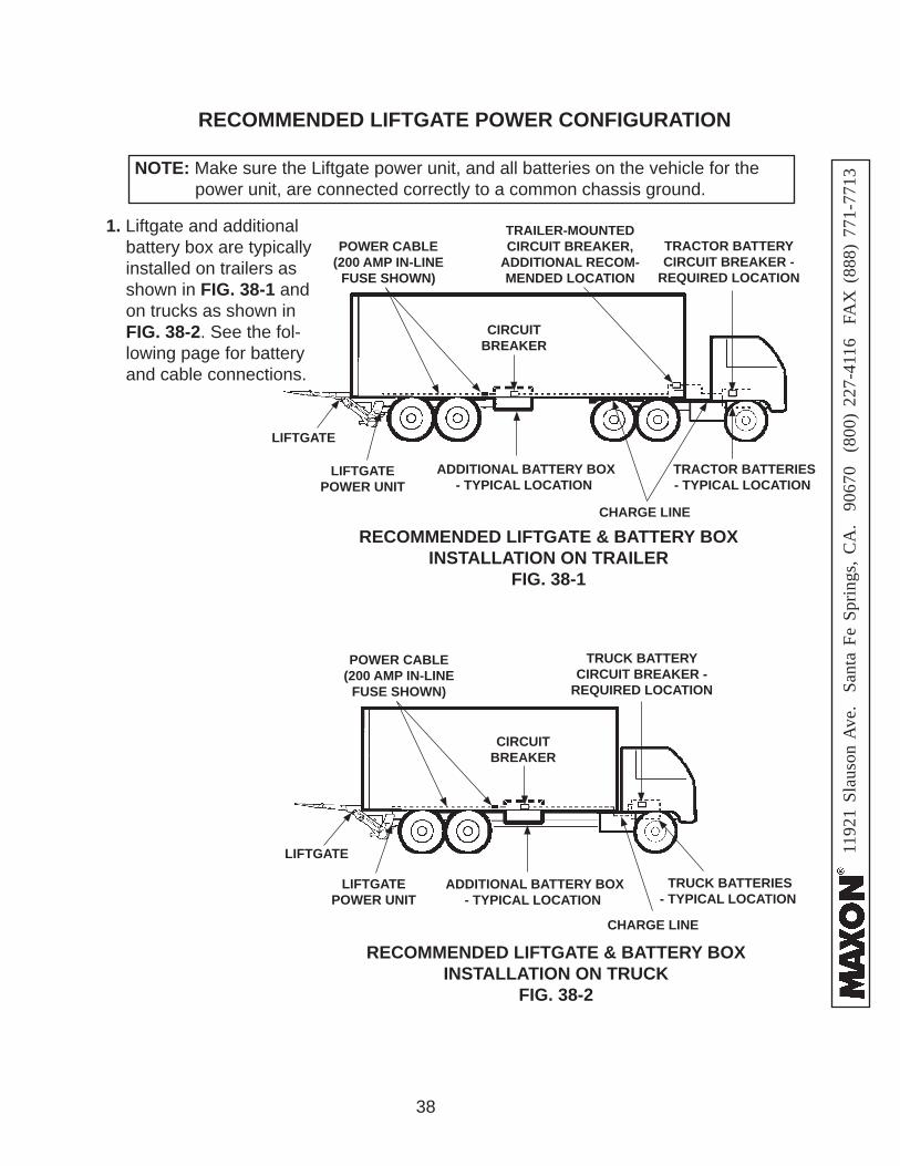
1. Liftgate and additional battery box are typically installed on trailers as shown in FIG. 38-1 and on trucks as shown in FIG. 38-2. See the fol-lowing page for battery and cable connections.
LIFTGATE
ADDITIONAL BATTERY BOX- TYPICAL LOCATION
RECOMMENDED LIFTGATE & BATTERY BOX INSTALLATION ON TRAILER
FIG. 38-1
TRAILER-MOUNTED CIRCUIT BREAKER,
ADDITIONAL RECOM-MENDED LOCATION
CIRCUITBREAKER
POWER CABLE (200 AMP IN-LINE
FUSE SHOWN)
CHARGE LINE
TRACTOR BATTERYCIRCUIT BREAKER -
REQUIRED LOCATION
LIFTGATE
ADDITIONAL BATTERY BOX- TYPICAL LOCATION
LIFTGATEPOWER UNIT
RECOMMENDED LIFTGATE & BATTERY BOX INSTALLATION ON TRUCK
FIG. 38-2
CIRCUITBREAKER
POWER CABLE (200 AMP IN-LINE
FUSE SHOWN)
CHARGE LINE
TRUCK BATTERYCIRCUIT BREAKER -
REQUIRED LOCATION
TRACTOR BATTERIES - TYPICAL LOCATION
TRUCK BATTERIES- TYPICAL LOCATION
RECOMMENDED LIFTGATE POWER CONFIGURATION
NOTE: Make sure the Liftgate power unit, and all batteries on the vehicle for the power unit, are connected correctly to a common chassis ground.
LIFTGATEPOWER UNIT
39
1192
1 Sl
auso
n A
ve.
Sant
a Fe
Spr
ings
, CA
. 90
670
(80
0) 2
27-4
116
FA
X (
888)
771
-771
3
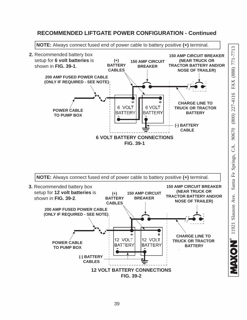
12 VOLT BATTERY CONNECTIONSFIG. 39-2
(-) BATTERY CABLES
150 AMP CIRCUIT BREAKER
(+)BATTERYCABLES
POWER CABLE TO PUMP BOX
3. Recommended battery box setup for 12 volt batteries is shown in FIG. 39-2.
200 AMP FUSED POWER CABLE(ONLY IF REQUIRED - SEE NOTE)
150 AMP CIRCUIT BREAKER(NEAR TRUCK OR
TRACTOR BATTERY AND/OR NOSE OF TRAILER)
CHARGE LINE TOTRUCK OR TRACTOR
BATTERY
(-) BATTERY CABLE
6 VOLT BATTERY CONNECTIONSFIG. 39-1
150 AMP CIRCUIT BREAKER
(+)BATTERYCABLES
POWER CABLE TO PUMP BOX
200 AMP FUSED POWER CABLE(ONLY IF REQUIRED - SEE NOTE)
2. Recommended battery box setup for 6 volt batteries is shown in FIG. 39-1.
CHARGE LINE TOTRUCK OR TRACTOR
BATTERY
NOTE: Always connect fused end of power cable to battery positive (+) terminal.
150 AMP CIRCUIT BREAKER(NEAR TRUCK OR
TRACTOR BATTERY AND/OR NOSE OF TRAILER)
RECOMMENDED LIFTGATE POWER CONFIGURATION - Continued
NOTE: Always connect fused end of power cable to battery positive (+) terminal.
40
1192
1 Sl
auso
n A
ve.
Sant
a Fe
Spr
ings
, CA
. 90
670
(80
0) 2
27-4
116
FA
X (
888)
771
-771
3
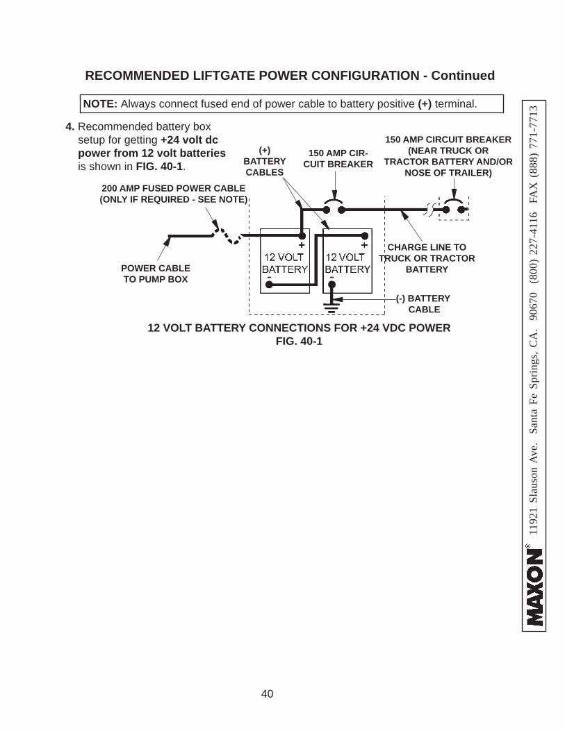
(-) BATTERY CABLE
12 VOLT BATTERY CONNECTIONS FOR +24 VDC POWERFIG. 40-1
150 AMP CIR-CUIT BREAKER
(+)BATTERYCABLES
POWER CABLE TO PUMP BOX
200 AMP FUSED POWER CABLE(ONLY IF REQUIRED - SEE NOTE)
CHARGE LINE TOTRUCK OR TRACTOR
BATTERY
150 AMP CIRCUIT BREAKER(NEAR TRUCK OR
TRACTOR BATTERY AND/OR NOSE OF TRAILER)
RECOMMENDED LIFTGATE POWER CONFIGURATION - Continued
4. Recommended battery box setup for getting +24 volt dc power from 12 volt batteries is shown in FIG. 40-1.
NOTE: Always connect fused end of power cable to battery positive (+) terminal.