168
Operation Manual 10th Edition RCP2 Series ROBO Cylinder Controller

Operation Manual 10th Edition
RCP2 Series ROBO Cylinder Controller

CAUTION 1. 24-V Power Supplies for Equipment Requiring a UL Certification
The controller with the maximum current of 2 A (RCP2-C/CG) and 6 A (RCP2-CF) are UL-certified. However, a UL certification requires that the 24-V power supplies used with the controller conform to Class 2. If the user’s equipment must receive a UL certification, please use an input power supply and an I/O power supply both conforming to Class 2.
2. Basic Parameter Settings
After applying power, at least the three parameters specified below must be set in accordance with the specific application. Inappropriate settings of these parameters will prevent the controller from operating properly, so exercise due caution. For details on how to set the parameters, refer to “Parameter Settings” in the operation manual for the PC or teaching pendant.
[1] Selecting the PIO pattern This controller provides six PIO (Parallel I/O) patterns to meet the needs of various applications. To select a desired PIO pattern, set a corresponding value from 0 to 5 in parameter No. 25 (PIO pattern selection). The factory setting is “0.”
Parameter No. 25 setting Feature of PIO pattern
0 Conventional This pattern is compatible with the pin assignments of the RCP controller.
1 Standard All functions of the RCP controller are available, plus the home-return command input, servo ON input, reset input, moving output and ready output.
2 64-point positioning Compared with the standard pattern offering only 16 positioning points, this pattern provides up to 64 positioning points. However, the servo ON input, ready output and zone output have been removed.
3 2 zone output signals Compared with the standard pattern offering only one zone output signal, this pattern provides two zone output signals. However, the moving output has been removed. The boundaries for the second zone output signal are specified in parameter Nos. 23 and 24.
4 Teaching This pattern allows for normal positioning operation, as well as jogging and writing of current position to a specified position using I/Os. Switching between the normal positioning mode and teaching mode is effected by the MODE input signal. The mode switching completion output has been added to indicate that the modes have been switched. However, the zone output has been removed. (Note) Position data can be rewritten up to around 100,000 times.
5 4 points (air cylinder) Use of the RCP2 as an air cylinder is assumed in this pattern. The number of positioning points is limited to four, but a direct command input and a position complete output are provided for each target position in line with the conventional practice of air cylinder control. This lets the user control the RCP2 just like an air cylinder.

[2] Enabling/disabling the servo ON input signal (SON)
The servo ON input signal has been added to allow for servo ON/OFF control on the PLC side. Depending on the needs, therefore, the user must enable/disable this signal. To select a desired setting, set “0” or “1” in parameter No. 21 (Servo ON input disable selection).
Enable (use) the signal 0 Disable (do not use) the signal 1
If “0” or “2” has been selected as the above PIO pattern, the servo ON signal is not provided. However, you must still set “1: [Disable]” in parameter No. 21 (SON). (If “0” is set, the servo will not turn ON.) The factory setting for this parameter is “1: [Disable].”
[3] Enabling/disabling the pause signal (*STP)
The pause signal uses the contact B logic to provide a failsafe function. Therefore, this signal must remain ON in normal conditions of use. (The pause signal must also remain ON when issuing movement commands from the teaching pendant or PC.) Since there are applications where this signal is not used, a parameter is provided to disable the pause signal so it doesn’t have to be turned ON. To select a desired setting, set “0” or “1” in parameter No. 15 (Pause input disable selection).
Enable (use) the signal 0 Disable (do not use) the signal 1
If the pause input is not used, set “1: [Disable]” in this parameter and the signal need not be turned ON. The factory setting for this parameter is “0: [Enable].”
3. Recommendation for Backing up Latest Data
This controller uses nonvolatile memory to store the position table and parameters. Normally the memory will retain the stored data even after the power is disconnected. However, the data may be lost if the nonvolatile memory becomes faulty. We strongly recommend that the latest position table and parameter data be backed up so that the data can be restored quickly in the event of power failure, or when the controller must be replaced for a given reason. The data can be backed up using the following methods: [1] Save to a CD or FD from the PC software. [2] Hand write the position table and parameter table on paper.
4. Compatibility of Teaching Pendant
The existing teaching pendants of <RCA-T> and <RCA-E> types can be used with the RCP2 controller, but your RCA-T/RCA-E teaching pendant will require some modification. If you are using a teaching pendant of either type, please send it to IAI. We will perform the necessary modification and return it to you as soon as possible. Teaching pendants that have already been modified have a specific code at the end of their serial number. Please check the serial number of your teaching pendant to see if it requires modification.
Teaching pendant model Code at the end of serial number
RCA-T …F3 (or later) RCA-E …H3 (or later) RCA-P …H3 (or later) RCB-J …B2 (or later)
5. PC Software Versions
The software versions that support this controller are 4.0.0.0 and later.

Safety Precautions (Please read before using the product.) Before installing, operating, maintaining or inspecting this product, please peruse this operating manual as well as the operating manuals and other related documentations for all equipment and peripheral devices connected to this product in order to ensure the correct use of this product and connected equipment/devices. Those performing installation, operation, maintenance and inspection of the product must have sufficient knowledge of the relevant equipment and their safety. The precautions provided below are designed to help you use the product safely and avoid bodily injury and/or property damage. In this operating manual, safety precautions are classified as “Danger,” “Warning,” “Caution” and “Note,” according to the degree of risk.
Danger Failure to observe the instruction will result in an imminent danger leading to death or serious injury.
Warning Failure to observe the instruction may result in death or serious injury.
Caution Failure to observe the instruction may result in injury or property damage.
Note The user should take heed of this information to ensure the proper use of the product, although failure to do so will not result in injury.
It should be noted that the instructions under the Caution and Note headings may also lead to serious consequences, if unheeded, depending on the situation. All instructions contained herein provide vital information for ensuring safety. Please read the contents carefully and handle the product with due caution. Please keep this operating manual in a convenient place for quick reference whenever needed, and also make sure that the manual will get to the end-user.
Danger [General]
Do not use this product for the following applications: 1. Medical equipment used to maintain, control or otherwise affect human life or physical health 2. Mechanisms and machinery designed for the purpose of moving or transporting people 3. Important safety parts of machinery This product has not been planned or designed for applications requiring high levels of safety. Use of this product in such applications may jeopardize the safety of human life. The warranty covers only the product as it is delivered.

[Installation]
Do not use this product in a place exposed to ignitable, inflammable or explosive substances. The product may ignite, burn or explode. Avoid using the product in a place where the main unit or controller may come in contact with water or oil droplets. Never cut and/or reconnect the cables supplied with the product for the purpose of extending or shortening the cable length. Doing so may result in fire.
[Operation]
If you are using a pace maker or other mechanical implant, do not come within one meter of the product. Doing so may cause the pace maker, etc., to malfunction. Do not pour water onto the product. Spraying water over the product, washing it with water or using it in water may cause the product to malfunction, resulting in injury, electric shock, fire, etc.
[Maintenance, Inspection, Repair]
Never modify the product. Unauthorized modification may cause the product to malfunction, resulting in injury, electric shock, fire, etc. Do not disassemble and reassemble the product. Doing so may result in injury, electric shock, fire, etc.
Warning [General]
Do not use the product outside the specifications. Using the product outside the specifications may cause it to fail, stop functioning or sustain damage. It may also significantly reduce the service life of the product. In particular, observe the maximum loading capacity and speed.
[Installation]
If the machine will stop in the case of system problem such as emergency stop or power failure, design a safety circuit or other device that will prevent equipment damage or injury.
Be sure to provide Class D grounding for the controller and actuator (formerly Class 3 grounding: Grounding resistance at 100 Ω or less). Leakage current may cause electric shock or malfunction.
Before supplying power to and operating the product, always check the operation area of the equipment to ensure safety. Supplying power to the product carelessly may cause electric shock or injury due to contact with the moving parts.
Wire the product correctly by referring to the operation manual. Securely connect the cables and connectors so that they will not be disconnected or come loose. Failure to do so may cause the product to malfunction or cause fire.
[Operation]
Do not touch the terminal block or various switches while the power is supplied to the product. Failure to observe this instruction may result in electric shock or malfunction. Before operating the moving parts of the product by hand (for the purpose of manual positioning, etc.), confirm that the servo is turned off (using the teaching pendant). Failure to observe this instruction may result in injury. Do not scratch the cables. Scratching, forcibly bending, pulling, winding, crushing with heavy object or pinching a cable may cause it to leak current or lose continuity, resulting in fire, electric shock, malfunction, etc.
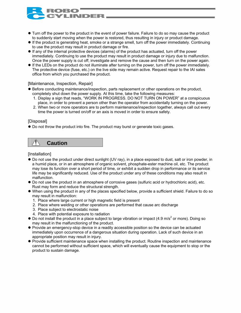
Turn off the power to the product in the event of power failure. Failure to do so may cause the product to suddenly start moving when the power is restored, thus resulting in injury or product damage.
If the product is generating heat, smoke or a strange smell, turn off the power immediately. Continuing to use the product may result in product damage or fire.
If any of the internal protective devices (alarms) of the product has actuated, turn off the power immediately. Continuing to use the product may result in product damage or injury due to malfunction. Once the power supply is cut off, investigate and remove the cause and then turn on the power again.
If the LEDs on the product do not illuminate after turning on the power, turn off the power immediately. The protective device (fuse, etc.) on the live side may remain active. Request repair to the IAI sales office from which you purchased the product.
[Maintenance, Inspection, Repair]
Before conducting maintenance/inspection, parts replacement or other operations on the product, completely shut down the power supply. At this time, take the following measures: 1. Display a sign that reads, “WORK IN PROGRESS. DO NOT TURN ON POWER” at a conspicuous
place, in order to prevent a person other than the operator from accidentally turning on the power. 2. When two or more operators are to perform maintenance/inspection together, always call out every
time the power is turned on/off or an axis is moved in order to ensure safety. [Disposal]
Do not throw the product into fire. The product may burst or generate toxic gases.
Caution [Installation]
Do not use the product under direct sunlight (UV ray), in a place exposed to dust, salt or iron powder, in a humid place, or in an atmosphere of organic solvent, phosphate-ester machine oil, etc. The product may lose its function over a short period of time, or exhibit a sudden drop in performance or its service life may be significantly reduced. Use of the product under any of these conditions may also result in malfunction.
Do not use the product in an atmosphere of corrosive gases (sulfuric acid or hydrochloric acid), etc. Rust may form and reduce the structural strength.
When using the product in any of the places specified below, provide a sufficient shield. Failure to do so may result in malfunction: 1. Place where large current or high magnetic field is present 2. Place where welding or other operations are performed that cause arc discharge 3. Place subject to electrostatic noise 4. Place with potential exposure to radiation
Do not install the product in a place subject to large vibration or impact (4.9 m/s2 or more). Doing so may result in the malfunctioning of the product.
Provide an emergency-stop device in a readily accessible position so the device can be actuated immediately upon occurrence of a dangerous situation during operation. Lack of such device in an appropriate position may result in injury.
Provide sufficient maintenance space when installing the product. Routine inspection and maintenance cannot be performed without sufficient space, which will eventually cause the equipment to stop or the product to sustain damage.

Always use IAI’s genuine cables for connection between the controller and the actuator. Also use IAI’s genuine products for the key component units such as the actuator, controller and teaching pendant.
Before installing or adjusting the product or performing other operations on the product, display a sign that reads, “WORK IN PROGRESS. DO NOT TURN ON POWER.” If the power is turned on inadvertently, injury may result due to electric shock or sudden activation of an actuator.
[Operation]
Turn on the power to individual equipment one by one, starting from the equipment at the highest level in the system hierarchy. Failure to do so may cause the product to start suddenly, resulting in injury or product damage.
Do not insert a finger or object in the openings in the product. It may cause fire, electric shock or injury. [Maintenance, Inspection, Repair]
Do not touch the terminals when performing an insulation resistance test. Electric shock may result. (Do not perform any withstand voltage test, since the product uses DC voltage.)
Note [Installation]
Do not place objects around the controller that will block airflows. Insufficient ventilation may damage the controller.
Do not configure a control circuit that will cause the load to drop in case of power failure. Configure a control circuit that will prevent the table or load from dropping when the power to the machine is cut off or an emergency stop is actuated.
[Installation, Operation, Maintenance]
When handling the product, wear protective gloves, protective goggles, safety shoes or other necessary gear to ensure safety.
[Disposal]
When the product becomes no longer usable or necessary, dispose of it properly as an industrial waste.
Others
IAI shall not be liable whatsoever for any loss or damage arising from a failure to observe the items specified in “Safety Precautions.”
If you have any question regarding the product, please contact your nearest IAI sales office. The addresses and phone numbers of our sales offices are provided at the end of this operation manual.

Before Use
Caution 1. Be sure to read this operation manual to ensure the proper use of this product. 2. Unauthorized use or reproduction of a part or all of this operation manual is prohibited. 3. IAI shall not be liable whatsoever for any loss or damage arising from a handling or operation not
specified in this operation manual. 4. The information contained in this operation manual is subject to change without notice.
Action to Be Taken in Case of Emergency
* If this product is found to be in a dangerous condition, immediately turn off all power switches of the main unit and connected equipment or immediately disconnect all power cables from the outlets. (“Dangerous condition” refers to a situation where the product is generating abnormal heat or smoke or has ignited and a fire or danger to human health is anticipated.)

Table of Contents
1. Overview ............................................................................................. 1 1.1 Introduction .................................................................................................................................... 1 1.2 Model Designation ......................................................................................................................... 2 1.3 Handling of Secondary Batteries for the Absolute Specification.................................................... 3 1.4 Safety Precautions ......................................................................................................................... 4 1.5 Warranty Period and Scope of Warranty ....................................................................................... 5
2. Specifications ...................................................................................... 6 2.1 Basic Specifications ....................................................................................................................... 6
2.1.1 Backup Batteries for the Absolute Specification .................................................................. 7 2.1.2 Specifications of the Large-Capacity Type (RCP2-CF) ....................................................... 8
2.2 Name and Function of Each Part of the Controller ........................................................................ 9 2.2.1 Names.................................................................................................................................. 9 2.2.2 Functions ............................................................................................................................. 9
2.3 External Dimensions .....................................................................................................................11 2.3.1 Standard Specification ........................................................................................................11 2.3.2 Absolute Specification with Battery Bracket ...................................................................... 12 Absolute Specification without Battery Bracket ................................................................. 13 2.3.3 Large-Capacity Type (RCP2-CF)....................................................................................... 14
3. Installation and Noise Elimination ..................................................... 15 3.1 Installation Environment............................................................................................................... 15 3.2 Power Supply ............................................................................................................................... 15 3.3 Noise Elimination and Grounding ................................................................................................ 15 3.4 Heat Radiation and Installation .................................................................................................... 17
4. Wiring ................................................................................................ 18 4.1 Internal Drive-Power Cutoff Relay Type (RCP2-C, RCP2-CF) .................................................... 18
4.1.1 Configuration...................................................................................................................... 18 4.1.2 External Connection Diagram............................................................................................ 19 4.1.3 Wiring the Power Supply/Emergency-Stop Switch............................................................ 20
4.2 External Drive-Power Cutoff Relay Type (RCP2-CG).................................................................. 27 4.2.1 Configuration...................................................................................................................... 27 4.2.2 External Connection Diagram............................................................................................ 28 4.2.3 Wiring the Power Supply/Motor Power Cutoff Relay ......................................................... 29
4.3 Connecting the I/O Cables........................................................................................................... 32 PIO pattern 0 [Conventional]................................................................................................... 32 PIO pattern 1 [Standard] ......................................................................................................... 33 PIO pattern 2 [64-point positioning] ........................................................................................ 34 PIO pattern 3 [2 zone output signals]...................................................................................... 35 PIO pattern 4 [Teaching] ......................................................................................................... 36 PIO pattern 5 [4 points] ........................................................................................................... 37

4.4 Connecting the Actuator............................................................................................................... 38 4.4.1 Motor Relay Cable ............................................................................................................. 38 4.4.2 Encoder Relay Cable......................................................................................................... 39
[Standard controller (2 A)] ....................................................................................................... 39 [Large-capacity controller (6 A)] .............................................................................................. 41
4.5 Connecting the Communication Cable ........................................................................................ 42
5. I/O Signal Control and Signal Functions ........................................... 43 5.1 PIO Patterns and Signal Assignments ......................................................................................... 43
5.1.1 Explanation of Signal Names............................................................................................. 44 PIO pattern = “0: [Conventional],” “1: [Standard],”
“2: [64-point positioning],” “3: [2 zone output signals]”............................................................ 44 PIO pattern = “4: [Teaching]”................................................................................................... 45 PIO pattern = “5: [4 points]...................................................................................................... 46
5.1.2 Signal Assignment Table for Respective PIO Patterns...................................................... 47 5.2 Interface Circuit ............................................................................................................................ 48
5.2.1 External Input Specifications.............................................................................................. 48 5.2.2 External Output Specifications........................................................................................... 49
5.3 Details of I/O Signal Functions..................................................................................................... 50 5.3.1. Details of Each Input Signal............................................................................................... 50
Start (CSTR)............................................................................................................................ 50 Command position number (PC1 to PC32) ............................................................................ 50 Pause (*STP) .......................................................................................................................... 50 Home return (HOME).............................................................................................................. 51 Servo ON (SON) ..................................................................................................................... 51 Alarm reset (RES)................................................................................................................... 51 Operation mode (MODE) ........................................................................................................ 51 Current-position write (PWRT)................................................................................................ 52 Jog (JOG+, JOG-)................................................................................................................... 52 Movement to each position (ST0 to ST3) ............................................................................... 52
5.3.2 Details of Each Output Signal............................................................................................ 53 Completed position number (PM1 to PM32)........................................................................... 53 Moving (MOVE) ...................................................................................................................... 53 Position complete (PEND) ...................................................................................................... 53 Home return completion (HEND)............................................................................................ 53 Zone (ZONE1, ZONE2) .......................................................................................................... 54 Current operation mode (MODES) ......................................................................................... 54 Write completion (WEND)....................................................................................................... 54 Completion of each position (PE0 to PE3) ............................................................................. 54 Ready (SRDY) ........................................................................................................................ 55 Alarm (*ALM)........................................................................................................................... 55 Emergency stop (*EMGS)....................................................................................................... 55
Output Signal Changes in Each Mode ........................................................................................... 55

6. Data Entry <Basics>.......................................................................... 56 6.1 Description of Position-Data Table ............................................................................................... 57
6.1.1 Relationship of Push Force at Standstill and Current-Limiting Value ................................ 60 Slider type
(1) SA5/SA6/SS type.................................................................................................................... 60 (2) SA7 type.................................................................................................................................. 60 (3) SM type ................................................................................................................................... 61
Rod type (1) RPA type ................................................................................................................................. 62 (2) RXA type ................................................................................................................................. 62 (3) RSA/RSW type........................................................................................................................ 63 (4) RMA/RMW type ...................................................................................................................... 63 (5) RFA/RFW type ........................................................................................................................ 64
6.2 Explanation of Modes................................................................................................................... 65 6.2.1 Positioning Mode ............................................................................................................... 65 6.2.2 Push & Hold Mode............................................................................................................. 65 6.2.3 Speed Change during Movement ...................................................................................... 67 6.2.4 Operation at Different Acceleration and Deceleration Settings ......................................... 67 6.2.5 Pause................................................................................................................................. 68 6.2.6 Zone Signal Output............................................................................................................ 69 6.2.7 Home Return...................................................................................................................... 69 6.2.8 Teaching Mode (Jogging/Teaching Using PIO) ................................................................. 70 6.2.9 Overview of the “4 Points” (Air Cylinder) Mode ................................................................. 71
6.3 Notes on the ROBO Gripper ........................................................................................................ 73
7. Operation <Practical Steps>.............................................................. 75 7.1 How to Start.................................................................................................................................. 75
7.1.1 Standard Specification ....................................................................................................... 75 7.1.2 Absolute Specification (Absolute Reset)............................................................................ 77
7.2 How to Execute Home Return ..................................................................................................... 80 7.2.1 Standard Specification ....................................................................................................... 80 7.2.2 Absolute Specification........................................................................................................ 81 7.2.3 Operation Timings at PIO Pattern = “0: [Conventional]” .................................................... 82 7.2.4 Operation Timings at PIO Pattern = “5: [4 Points]” ............................................................ 83 7.2.5 Operation Timings at PIO Pattern ≠ “0: [Conventional]” or “5: [4 Points]” ...................... 84
7.3 Home Return and Movement after Start (PIO Pattern = “1: [Standard]”)..................................... 85 7.4 Positioning Mode (Back and Forth Movement between Two Points) .......................................... 87 7.5 Push & Hold Mode ....................................................................................................................... 89
7.5.1 Return Action after Push & Hold by Relative Coordinate Specification ............................. 90 7.6 Speed Change during Movement ................................................................................................ 91 7.7 Operation at Different Acceleration and Deceleration Settings.................................................... 93 7.8 Pause ........................................................................................................................................... 95 7.9 Zone Signal Output ...................................................................................................................... 97 7.10 Incremental Moves....................................................................................................................... 99

7.11 Notes on Incremental Mode....................................................................................................... 101 7.12 Jogging/Teaching Using PIO...................................................................................................... 103 7.13 Operation in the “4 Points (Air Cylinder)” Mode......................................................................... 105
8. Parameters...................................................................................... 109 8.1 Parameter Classification ............................................................................................................ 109 8.2 Parameter Table......................................................................................................................... 109 8.3 Parameter Settings .....................................................................................................................110
8.3.1 Parameters Relating to the Actuator Stroke Range..........................................................110 Soft limit .................................................................................................................................110 Zone boundary.......................................................................................................................110 Home return direction ............................................................................................................111 Home return offset .................................................................................................................111
8.3.2 Parameters Relating to the Actuator Operating Characteristics.......................................111 PIO jog speed ........................................................................................................................111 Default speed.........................................................................................................................111 Default acceleration/deceleration...........................................................................................111 Default positioning band (in-position) ....................................................................................112 Default acceleration only MAX flag........................................................................................112 Push & hold stop judgment period.........................................................................................112 Current-limiting value at standstill during positioning.............................................................113 Current-limiting value during home return .............................................................................113 Direction of excitation phase signal detection........................................................................113
8.3.3 Parameters Relating to the External Interface..................................................................114 PIO pattern selection .............................................................................................................114 Movement command type......................................................................................................115 Pause input disable selection ................................................................................................116 Servo ON input disable selection...........................................................................................116 Serial communication speed..................................................................................................116 Minimum delay time for slave transmitter activation..............................................................116
8.3.4 Servo Gain Adjustment .....................................................................................................116 Servo gain number.................................................................................................................116
9. Controlling Multiple Controllers via Serial Communication.............. 117 9.1 Basic Specifications ....................................................................................................................117 9.2 Connection Example ...................................................................................................................117 9.3 SIO Converter .............................................................................................................................118 9.4 Address Switch .......................................................................................................................... 120 9.5 Connection Cables..................................................................................................................... 120 9.6 Detail Connection Diagram ........................................................................................................ 121

10. Troubleshooting............................................................................... 122 10.1 Action to Be Taken upon Occurrence of Problem...................................................................... 122 10.2 Alarm Level Classification.......................................................................................................... 123 10.3 Alarm Description Output Using PIO ......................................................................................... 124 10.4 Alarm Description and Cause/Action ......................................................................................... 125
(1) Message level alarms ........................................................................................................... 125 (2) Operation-cancellation level alarms...................................................................................... 126 (3) Cold-start level alarms .......................................................................................................... 129
10.5 Messages Displayed during Operation Using the Teaching Pendant or PC Software .............. 131 10.6 Specific Problems....................................................................................................................... 133
I/O signals cannot be exchanged with the PLC. ................................................................... 133 The RDY lamp does not illuminate after the power is input.................................................. 133 Only the RDY lamp illuminates when the servo ON signal is input after the power
was input. .............................................................................................................................. 133 Both the RDY lamp and ALM lamp illuminate when the power is input................................ 133 Home return ends in the middle in a vertical application. ..................................................... 134 Noise occurs during downward movements in a vertical application. .................................. 134 Vibration occurs when the actuator is stopped. .................................................................... 134 The actuator overshoots when decelerated to a stop........................................................... 134 The home and target positions sometimes shift. .................................................................. 134 The speed is slow during push & hold operation. ................................................................. 134 The actuator moves only a half of, or twice as much as, the specified movement. ............. 135 A servo error occurred while the actuator was moving (ROBO Gripper).............................. 135 Abnormal operation results when the servo is turned ON after the power ON..................... 136 The ALM lamp blinks when the power is cut off.................................................................... 136
11. Function Check and Replacement of the Radiating Fan................. 137
* Appendix ................................................................................................ 139 List of Supported Actuator Specifications............................................................................... 139 Example of Basic RCP2 Positioning Sequence.................................................................... 149 Recording of Position-Data Table............................................................................................ 152 Recording of Parameters.......................................................................................................... 154

1
1. Overview 1.1 Introduction Thank you for purchasing the RCP2 controller. This manual explains the features and operating procedures of the product. If not used or handled properly, even a brilliant product cannot fully demonstrate its function or may cause an unexpected breakdown or end its life prematurely. Please read this manual carefully and handle the product with utmost care while ensuring its correct operation. Keep this manual in a convenient place so the relevant sections can be referenced readily when necessary. If you are also using any of IAI’s various actuators and/or optional PC software or teaching pendant, also refer to the operation manual for each item.

2
1.2 Model Designation
Controller with a power-supply capacity of 2 A
Controller with a power-supply capacity of 6 A (Large-capacity type)
<Series> <Safety circuit type> C: Built-in cutoff relay CG: External cutoff relay <Actuator type> Slider, ball-screw type
Slider, belt type
Rod type
Rod, splash-proof type
Gripper
Rotary
<Absolute battery bracket> Blank: Without bracket K: With bracket <I/O signal type> Blank: NPN (sink type) P: PNP (source type) <Supply voltage>
<Motor type> PM: Pulse motor
<Encoder type> I: Incremental A: Absolute
<Series>
<Safety circuit type> CF: Built-in cutoff relay
<Actuator type> High-speed ball-screw type
High-thrust rod type
Waterproof type
<I/O signal type> Blank: NPN (sink type) P: PNP (source type) <Supply voltage> <Motor type> PM: Pulse motor <Encoder type> I: Incremental

3
1.3 Handling of Secondary Batteries for the Absolute Specification Observe the safety precautions specified below when handling the secondary batteries: 1. Never attempt to disassemble the batteries. Strong alkali battery fluid will damage the skin or clothes. 2. Never short the battery terminals (i.e. by allowing the positive and negative terminals to make direct
contact). Doing so may damage the equipment or cause burns due to the generation of heat. 3. Never throw the batteries into a fire, because it may cause them to explode. Also avoid immersing the
batteries in water, which can result in loss of battery function. 4. Do not solder the batteries directly. The safety valve inside the battery cap may be damaged, resulting
in a breakdown of the safety mechanism. 5. If the battery connector remains connected for a long time without a supply of power, a deep discharge
may occur and cause the battery fluid to leak or allow the battery performance or life to deteriorate/shorten significantly. If the equipment is to be relocated or modified and the power will not be supplied for a prolonged period, first disconnect the battery connector.
6. When disposing of used batteries, drop them into the collection box at an authorized recycle store or take other appropriate steps.
* We have made every effort to ensure accuracy of the information provided in this manual. Should you
find an error, however, or if you have any comment, please contact IAI. Keep this manual in a convenient place so it can be referenced readily when necessary.

4
1.4 Safety Precautions
Read the following information carefully and provide safety measures with due consideration. This system product has been developed as a drive component for automated machinery and the like, and is therefore designed not to generate excessive torque or speed beyond the levels needed to drive automated equipment. However, the following instructions must be strictly observed to prevent an unexpected accident. 1. Do not handle this product in any manner not specified in this manual. If you have questions regarding
any of the information provided in this manual, please contact IAI. 2. Always use the specified genuine parts to wire your RCP2 controller and an actuator. 3. Do not enter the operating range of the machine while the machine is operating or is able to operate
(the controller power is ON). If the machine is used in a place accessible to other people, enclose its operating range using a safety cage, etc.
4. Always turn off the power supply to the controller before assembling/adjusting or
maintaining/inspecting the machine. During assembly/adjustment or maintenance/inspection, put a plate or other visible sign in a conspicuous place indicating that work is in progress. The operator should keep the entire power cable beside him or her to prevent another person from inadvertently plugging in the cable.
5. If two or more persons work together, set signaling methods so each person can confirm the safety of
other(s) during work. Especially when the work requires an axis or axes to be moved—with or without the power and by motor drive or manual operation—the person moving each axis should always call out beforehand to ensure safety.
6. If you have extended a cable or made other alteration to the standard wiring specification, thoroughly
check the wiring and ensure absence of problem before turning on the power, in order to prevent malfunction due to miswiring.

5
1.5 Warranty Period and Scope of Warranty The RCP2 controller you have purchased passed IAI’s shipping inspection implemented under the strictest standards. The unit is covered by the following warranty: 1. Warranty Period
The warranty period shall be one of the following periods, whichever ends first: • 18 months after shipment from our factory • 12 months after delivery to a specified location
2. Scope of Warranty
If an obvious manufacturing defect is found during the above period under an appropriate condition of use, IAI will repair the defect free of charge. Note, however, that the following items are excluded from the scope of warranty:
• Aging such as natural discoloration of coating • Wear of a consumable part due to use • Noise or other sensory deviation that doesn’t affect the mechanical function • Defect caused by inappropriate handling or use by the user • Defect caused by inappropriate or erroneous maintenance/inspection • Defect caused by use of a part other than IAI’s genuine part • Defect caused by an alteration or other change not approved by IAI or its agent • Defect caused by an act of God, accident, fire, etc.
The warranty covers only the product as it has been delivered and shall not cover any losses arising in connection with the delivered product. The defective product must be brought to our factory for repair.
Please read carefully the above conditions of warranty.

6
2. Specifications 2.1 Basic Specifications
Specification item Internal Drive-Power Cutoff Relay Type
External Drive-Power Cutoff Relay Type
Model RCP2-C-*** (Note) RCP2-CG-*** (Note)
Number of controlled axes 1 axis/unit
Supply voltage 24 VDC ±10%
Supply current 2 A max.
Control method Weak field-magnet vector control (patent pending)
Encoder resolution 800 P/rev
Positioning command Position number specification Direct specification
Position number Standard 16 points, maximum 64 points
Backup memory Position number data and parameters are saved in nonvolatile memory. Serial EEPROM can be rewritten 100,000 times.
PIO 10 dedicated inputs/10 dedicated outputs. Selectable from five patterns.
LED indicators RDY (green), RUN (green), ALM (red)
Communication RS485 1 channel (terminated externally)
Encoder interface Incremental specification conforming to EIA RS-422A/423A Forced release of electromagnetic brake Toggle switch on front panel of enclosure
Actuator cable: 20 m or less Cable length
PIO cable: 5 m or less
Insulation strength 500 VDC, 10 MΩ
Environment Operating temperature 0 to 40°C
Operating humidity 85%RH or less (non-condensing)
Operating environment Not subject to corrosive gases.
Storage temperature -10 to 65°C
Storage humidity 90%RH or less (non-condensing)
Vibration resistance 10 to 57 Hz in XYZ directions / Pulsating amplitude: 0.035 mm (continuous), 0.075 mm (intermittent)
Protection class IP20
Weight 300 g or less
External dimensions 35 W x 178.5 H x 68.1 D mm
(Note) *** indicates the actuator type.

7
2.1.1 Backup Batteries for the Absolute Specification The absolute-specification controller uses secondary batteries (nickel metal hydride cells) to retain absolute counter data in the FPGA (field-programmable gate array) after the power is cut off, and also to supply power to the encoder’s drive circuit intermittently. (1) Battery specification
Item Description Classification Cylindrical sealed nickel metal hydride cell Manufacturer Matsushita Battery Industrial
Model AB-4 Nominal voltage 4.8 V (1.2 V x 4) Rated capacity 1900 mAh (average capacity: 2050 mAh)
Average life Approx. 4 years Charging time Approx. 48 hours (at ambient temperature of 20°C)
Retention time after power cutoff Approx. 250 hours (when the batteries are fully charged, at ambient temperature of 20°C)
(2) Charging the batteries
Be sure to charge the batteries when the controller is powered up for the first time after delivery, and also after new batteries have been installed. The batteries are charged automatically while the power is being supplied to the controller, so keep the main power on for at least 48 hours. The actuator can be moved and the position table changed while the batteries are charging. Additionally, charge the batteries for at least 48 hours after the power supply to the controller has been cut off for a prolonged period (within the specified battery-retention time). (3) Replacing the batteries
Batteries are consumable parts. Repeated charging and discharging of the batteries will diminish their initial performance characteristics. If the retention time has decreased significantly, the batteries may have reached the end of their useful life. If this should occur, replace the batteries. The batteries should be replaced approximately four years after the controller is first connected to your equipment, although the specific timing will vary depending on the ambient temperature and conditions of charge/discharge. The label on the battery unit shows a reference date, which is four years from the shipment date. Use this date to determine when the batteries should be replaced.
Note: (1) Applying vibration, impact or other external force to the actuator or moving the slider, etc., while the power is off will erase the absolute data.
When the power is input again, the *ALM signal will turn OFF, the ALM lamp will illuminate and the message “Absolute encoder error (2)” or “Absolute encoder error (3)” will be displayed.
In this case, you must reset the alarm and perform a home return. Never move the slider or rod while the power is off! (2) It is recommended that the batteries be charged at normal temperature (+10 to +30°C) to
prevent extreme temperatures from negatively affecting the charging efficiency. Temperatures exceeding 45°C may cause performance deterioration or the leakage of
battery fluid.

8
2.1.2 Specifications of the Large-Capacity Type (RCP2-CF)
Specification item Internal Drive-Power Cutoff Relay Type
Model RCP2-CF-***
Number of controlled axes 1 axis/unit
Supply voltage 24 VDC ±10%
Supply current 6 A max.
Control method Weak field-magnet vector control (patent pending)
Encoder resolution 800 P/rev
Positioning command Position number specification Direct specification
Position number Standard 16 points, maximum 64 points
Backup memory Position number data and parameters are saved in nonvolatile memory. Serial EEPROM can be rewritten 100,000 times.
PIO 10 dedicated inputs/10 dedicated outputs. Selectable from five patterns.
LED indicators RDY (green), RUN (green), ALM (red)
Communication RS485 1 channel (terminated externally)
Encoder interface Incremental specification conforming to EIA RS-422A/423A Forced release of electromagnetic brake Toggle switch on front panel of enclosure
Actuator cable: 20 m or less Cable length
PIO cable: 5 m or less
Insulation strength 500 VDC, 10 MΩ
Environment Operating temperature 0 to 40°C
Operating humidity 85%RH or less (non-condensing)
Operating environment Not subject to corrosive gases.
Storage temperature -10 to 65°C
Storage humidity 90%RH or less (non-condensing)
Vibration resistance 10 to 57 Hz in XYZ directions / Pulsating amplitude: 0.035 mm (continuous), 0.075 mm (intermittent)
Protection class IP20
Weight 300 g or less
External dimensions 35 W x 180 H x 71.6 D mm

9
2.2 Name and Function of Each Part of the Controller 2.2.1 Names 2.2.2 Functions [1] Battery connector A connector for the absolute data retention batteries. [2] Status indicator LEDs
RDY: When lit, this LED indicates that 24V power is supplied and the CPU is operating. RUN: This LED indicates the servo status. Lit = Servo is ON, Unlit = Servo is OFF. ALM: When lit, this LED indicates that an alarm is present, or an emergency stop has been actuated
or the motor drive power is cut off. With the absolute specification controller, a blinking ALM LED indicates that the battery voltage has dropped to approx. 4.1 V or below when the power is cut off.
[3] PIO pattern number label (IOPN) Write down the PIO pattern selected in parameter No. 25 on this label. (This will facilitate maintenance if multiple controllers are used in different patterns.) [4] Teaching pendant/PC connector (SIO) A connector for the dedicated teaching pendant or PC communication cable. This cable is also used to link two or more controllers to enable serial communication among them.
RDY (green) • RUN (green) • ALM (red) [2] Status indicator LEDs
[3] PIO pattern number label
[4] Teaching pendant/ PC connector
[5] Motor connector
[6] Power/emergency-stop terminal block
[7] I/O signal connector [8] Address switch [9] PORT switch [10] Encoder connector [11] Brake release switch
[1] Battery connector (absolute specification)

10
[5] Motor connector (MOT) A connector for the actuator’s motor power cable. [6] Power/emergency-stop terminal block [Built-in cutoff relay type RCP2-C, RCP2-CF]
S1, S2
Provide a contact output for the emergency-stop button on the teaching pendant. Port switch ON = Emergency-stop button output (Contact B) Port switch OFF = ON in normal conditions of use (Emergency-stop button output is disabled)
MPI, MPO
Provide a contact for cutting off the motor drive power. MPI and MPO represent the input side and output side of the motor power supply, respectively. (Short these terminals using a jumper wire if not used. The controller is shipped with MPI and MPO shorted.)
24V Positive side of the 24-V power supply N Negative side of the 24-V power supply
EMG Emergency-stop input [External cutoff relay type RCP2-CG]
S1, S2
Provide a contact output for the emergency-stop button on the teaching pendant. Port switch ON = Emergency-stop button output (Contact B) Port switch OFF = ON in normal conditions of use (Emergency-stop button output is disabled)
MPI, MPO Provide a contact for cutting off the motor drive power. MPI and MPO represent the input side and output side of the motor power supply, respectively. (Connect an external safety circuit.)
24V Positive side of the 24-V power supply N Negative side of the 24-V power supply
FG FG of the 24-V power supply [7] I/O signal connector (PIO) A PIO cable connector to the host controller (PLC, etc.). [8] Address switch (ADRS) A switch for setting the address for the controller axis. If two or more controllers are connected in the serial communication mode, do not specify duplicate controller addresses.
Setting range: 0 to F (A maximum of 16 controllers can be connected.) [9] PORT switch (PORT) A switch for enabling/disabling the serial communication port. Set this switch to ON when connecting the controller to a teaching pendant or PC. Set it to OFF if no teaching pendant or PC is connected. * If this switch is turned ON without connecting a teaching pendant or PC, an emergency stop will be
actuated. [10] Encoder connector (ENC) A connector for the actuator’s encoder/brake cables. [11] Brake release switch (BK) A switch for forcibly releasing the brake when the actuator is used with a brake option.
RLS: Brake is forcibly released NOM: Normal setting (Brake is controlled by the controller)

11
2.3 External Dimensions 2.3.1 Standard Specification (RCP2-***-I ) An external view and dimensions of the product are shown below.
(Mou
ntin
g di
men
sion
)

12
2.3.2 Absolute Specification with Battery Bracket (RCP2-***-A- -K)
*Weight: 660 g
(Mou
ntin
g di
men
sion
)

13
Absolute Specification without Battery Bracket (RCP2-***-A- )
*Weight: 460 g
(Mou
ntin
g di
men
sion
)

14
2.3.3 Large-Capacity Type (RCP2-CF-***)
*Weight: 250 g
(Mou
ntin
g di
men
sion
)
Built-in radiating fan

15
3. Installation and Noise Elimination
Pay due attention to the installation environment of the controller. 3.1 Installation Environment (1) When installing and wiring the controller, do not block the cooling ventilation holes. (Insufficient
ventilation will not only prevent the controller from demonstrating its full performance, but it may also cause breakdown.)
(2) Prevent foreign matter from entering the controller through the ventilation holes. Since the enclosure of the controller is not dustproof or waterproof (oilproof), avoid using the controller in a place subject to significant dust, oil mist or splashes of cutting fluid.
(3) Do not expose the controller to direct sunlight or radiating heat from a large heat source such as a heat treatment furnace.
(4) Use the controller in an environment free from corrosive or inflammable gases, under a temperature of 0 to 40°C and humidity of 85% or less (non-condensing).
(5) Use the controller in an environment where it will not receive any external vibration or shock. (6) Prevent electrical noise from entering the controller or its cables. 3.2 Power Supply The power supply specification is 24 VDC ± 10%. (Supply current: 2 A max.) 3.3 Noise Elimination and Grounding This section explains how to eliminate noise in the use of the controller. (1) Wiring and power supply [1] Provide a dedicated class D grounding using a wire with a size of 2.0 to 5.5 mm2 or larger.
Class D grounding Good Avoid this grounding method.
Controller Other equipment Controller
Other equipment
Use a cable of a maximum possible size and keep the wiring length at a minimum.
Metal frame

16
[2] Precautions regarding wiring method Use a twisted cable for connection to the 24-VDC external power supply. Separate the controller cables from high-power lines such as a cable connecting to a power circuit. (Do not bundle together the controller cables with high-power lines or place them in the same cable duct.) When extending the supplied motor cable or encoder cable, consult IAI’s Technical Support. (2) Noise sources and elimination Among the numerous noise sources, solenoid valves, magnet switches and relays are of particular concern when building a system. Noise from these sources can be eliminated by implementing the measures specified below. [1] AC solenoid valves, magnet switches and relays Measure: Install a surge absorber in parallel with the coil. [2] DC solenoid valves, magnet switches and relays Measure: Install a diode in parallel with the coil. Determine the diode capacity in accordance with the
load capacity.
In a DC circuit, connecting a diode in reverse polarity will damage the diode, internal parts of the controller and/or DC power supply, so exercise due caution.
Point Install a surge absorber to each coil over a minimum wiring length.Installing a surge absorber to the terminal block or other part will be less effective because of a longer distance from the coil.
17
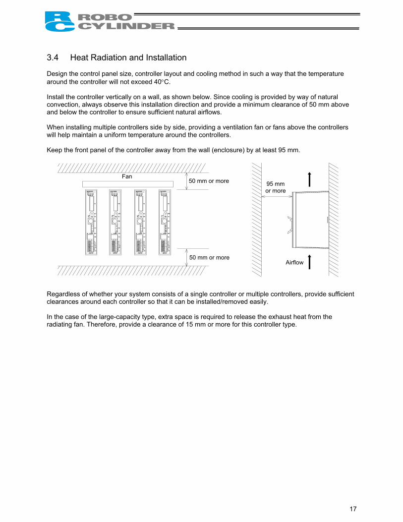
3.4 Heat Radiation and Installation Design the control panel size, controller layout and cooling method in such a way that the temperature around the controller will not exceed 40°C. Install the controller vertically on a wall, as shown below. Since cooling is provided by way of natural convection, always observe this installation direction and provide a minimum clearance of 50 mm above and below the controller to ensure sufficient natural airflows. When installing multiple controllers side by side, providing a ventilation fan or fans above the controllers will help maintain a uniform temperature around the controllers. Keep the front panel of the controller away from the wall (enclosure) by at least 95 mm. Regardless of whether your system consists of a single controller or multiple controllers, provide sufficient clearances around each controller so that it can be installed/removed easily. In the case of the large-capacity type, extra space is required to release the exhaust heat from the radiating fan. Therefore, provide a clearance of 15 mm or more for this controller type.
Fan 50 mm or more
50 mm or more Airflow
95 mm or more

18
4. Wiring 4.1 Internal Drive-Power Cutoff Relay Type (RCP2-C, RCP2-CF) 4.1.1 Configuration
Note: Connect one end of the EMG switch to the 24-V output of the input power supply and the other end to the S1 terminal. Also short the S2 and EMG terminals using a jumper wire.
S1 S2 MPI MPO 24V N EMG
PERSONAL COMPUTER
Standard teaching pendant <RCA-T> Optional
Cable length: 5 m
External unit <RCB-105-2> Cable length: 2 m <RCB-105-5> Cable length: 5 m
Optional
PC
PC software <RCB-101-MW>
Optional
External EMG switch
Input power supply 24 VDC 24V 0
Host system <PLC>
Supplied flat cable
Cable length: 2 m
ROBO cylinder Cable length: 5 m
Optional
* If the PLC is not used, disable the servo ON input and pause input using the applicable parameters.
Do not connect or disconnect the connectors while the power is on, except for the communication port connector (SIO). To connect or disconnect the SIO, do so after turning off the PORT switch. Failure to do so may result in breakdown.

19
4.1.2 External Connection Diagram An example of standard wiring is shown below. (Note) The encoder cable shown in the example is the standard cable for the controller with the
maximum current of 2 A. As for the robot cable or the cable for the large-capacity type, refer to 4.4.2, “Encoder Relay
Cable.”
Blue Black White Red Black Green
Orange (black 2)
Orange (red 2)
Yellow (black 1)
Yellow (red 1)
White (black 1)
White (red 1)
Light blue (black 1)
Light blue (red 1)
Controller
Connected to teaching pendant or PC
External EMG switch
Input power supply 24 VDC 24V 0V FG
Host system
flat cable
Refer to 4.3, “Connecting the I/O Cables,” for the connection of I/O signals.
(PORT switch)
Terminal block
Actuator
Motor
Encoder
Holding brake
Brake release switch
Tighten together with the mounting screw.
Yellow

20
4.1.3 Wiring the Power Supply/Emergency-Stop Switch (1) Wiring the power supply To connect multiple controllers, provide a relay terminal block. Use a power cable satisfying the following specifications:
Item Specification Applicable wire length Single wire: φ1.0 / Stranded: 0.8 mm2, AWG size 18 (copper wire) Stripped wire length 10 mm Temperature rating of insulating sheath 60°C or above
* Use a flathead screwdriver with a blade tip of approx. 2.6 mm to push in the wire.
Notes on wiring the absolute-specification controller [1] When connecting a relay to the 24-V line, be sure to install it on the positive side of the 24-V power
supply.
Keep the negative side of the 24-V power supply connected without cutting it off with a relay. If a relay is installed on both the positive and negative sides, an ABS error may generate.
[2] Connect a surge killer to the relay contact.
Chattering of the relay may have negative effect on the controller. Connect a surge killer to prevent malfunction.
Recommended product: Spark Killer by Okaya
Electric Industries Model: CR-50500 Capacitance: 0.5 µF ± 20% Resistance: 50 Ω (1/2W) ± 30%
24V 0V FG
S1 S2 MPIMPO 24V N EMG
Input power supply 24 VDC (2 A max. per controller)
Surge killer
Relay
Do not install a relay on the negative side.
RCP2- ABS
24V+
N 24VPS AC

21
(2) Wiring the emergency-stop switch In many cases multiple controllers are used in a single system. To provide an emergency-stop function for the entire system, the controller circuit is designed in such a way that a single EMG switch is able to actuate an emergency stop in all connected controllers.
[Internal emergency-stop circuit]
(Note) The current consumption of the internal relay is 10 mA or less.
(Reference) Cutoff voltage Cutoff current EMG switch on teaching pendant 30 VDC 3 A PORT switch 24 VDC 0.1 A
[Example of recommended circuit] (Note) To cut off the motor drive power supply in conformance with safety category 2, connect 24V to the
EMG terminal and a contactor or other contact device to the MPI/MPO terminals. (Refer to 4.2.3; rush current: 8 A.)
MPO
MPI
S1
S2
24V
N
EMG
S1 S2 CR
ON OFF
MPI MPO
24V
EMG
N
CR
CR
24V 0V
PORT switch
Teaching pendant
Relay
Motor power supply
External EMG reset switch
External EMG circuit
EMG switch on teaching pendant
ON OFF
Input power supply (C: 2 A max.) (CF: 6 A max.) 24V
0V
N
PORT switch
Relay
EMG signal
Controller power supply
RCP2 controller
RCP2 controller
Coil current: 0.1 A or less
(3 A)
(0.1 A)

22
Representative connection examples are explained below.
Connecting the teaching pendant directly to the controller (Parallel connection with the PLC) [1] Connecting multiple controllers (8 units or less) using a single power supply • Short the MPI and MPO terminals using a jumper wire. (The controller is shipped with these terminals
shorted.) • Connect one end of the EMG signal to the 24-V output of the input power supply and the other end to
the S1 terminal. Then, provide connections by sequentially connecting the S2 terminal of controller 1 to the S1 terminal of controller 2, the S2 terminal of controller 2 to the S1 terminal of controller 3, and so on, and connect the S2 terminal on the last controller to the EMG terminals on all controllers. Use a relay terminal block for connection to the EMG terminals. (Note) Do not connect two or more wires to one terminal.

23
[Controller 1] [Controller 2] [Controller 3] [Controller 4]
EMG signal 24V 0V
MPO
MPI
24V
EMG
PORT switch
Teaching pendant
Relay
ON
OFF
S1 S2
N
MPO
MPI
24V
EMG
PORT switch
Teaching pendant
Relay
ON
OFF
S1 S2
N
MPO
MPI
24V
EMG
PORT switch
Teaching pendant
Relay
ON
OFF
S1 S2
N
MPO
MPI
24V
EMG
PORT switch
Teaching pendant
Relay
ON
OFF
S1 S2
N
24
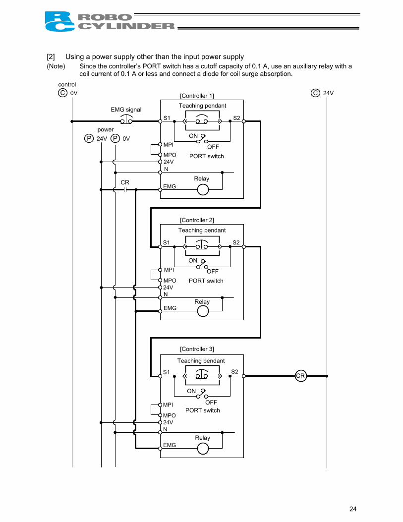
[2] Using a power supply other than the input power supply (Note) Since the controller’s PORT switch has a cutoff capacity of 0.1 A, use an auxiliary relay with a
coil current of 0.1 A or less and connect a diode for coil surge absorption.
C 0V control
C 24V
P 24V power
P 0V
CR
CR
[Controller 1] [Controller 2] [Controller 3]
EMG signal
MPO
MPI
24V
EMG
PORT switch
Teaching pendant
Relay
ON
OFF
S1 S2
N
MPO
MPI
24V
EMG
PORT switch
Teaching pendant
Relay
ON
OFF
S1 S2
N
MPI
24V
EMG
PORT switch
Teaching pendant
Relay
ON
OFF
S1 S2
N
MPO
25
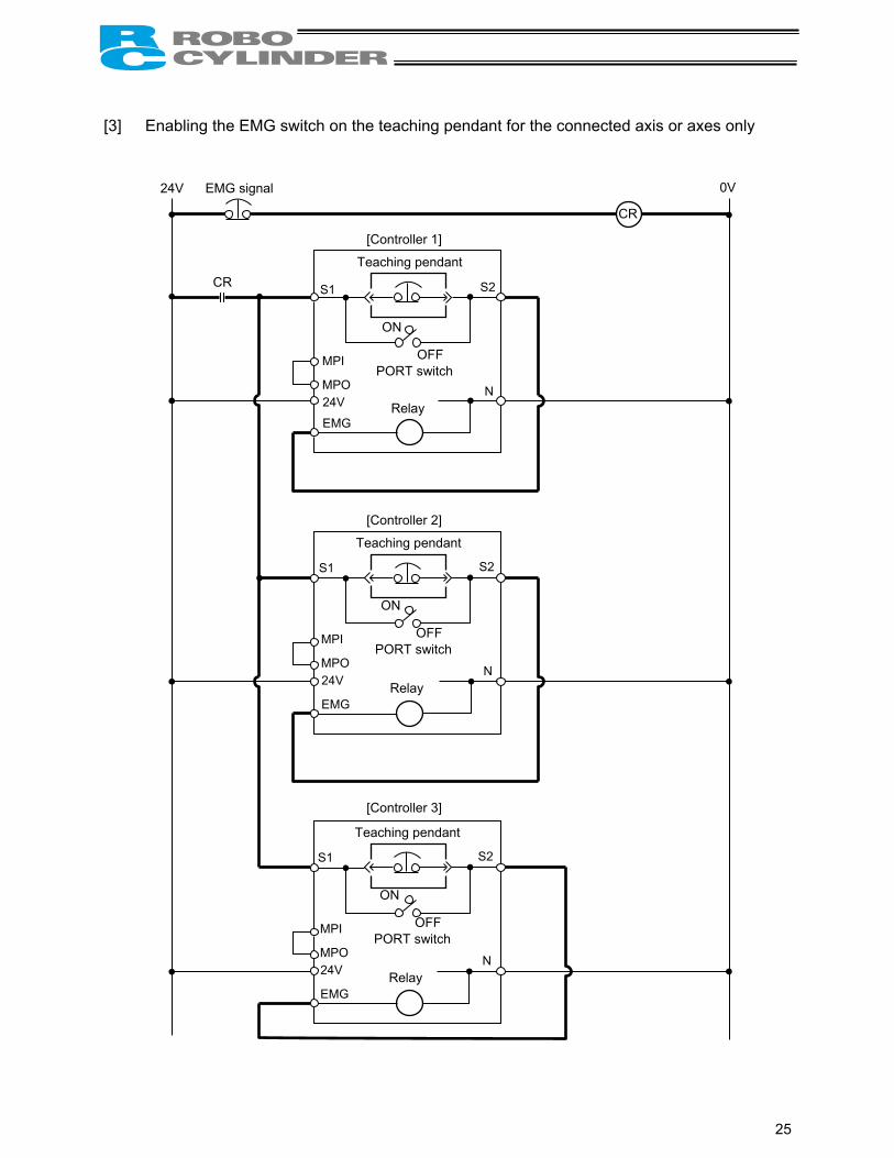
[3] Enabling the EMG switch on the teaching pendant for the connected axis or axes only
CR
[Controller 1]
[Controller 2] [Controller 3]
EMG signal
Teaching pendant
24V 0V
MPO
MPI
24V EMG
PORT switch
Relay
ON
OFF
S1 S2
N
MPO
MPI
24V
EMG
PORT switch
Relay
ON
OFF
S1 S2
N
Teaching pendant
MPO
MPI
24V
EMG
PORT switch
Relay
ON
OFF
S1 S2
N
Teaching pendant
CR

26
Connecting the teaching pendant to a SIO converter (Serial connection with the PLC) Configure the contact circuit for the EMG switch on the teaching pendant using EMG1/EMG2 on the
power/emergency-stop terminal block on the SIO converter. (S1/S2 on the controller’s terminal block are not used.)
CR
EMG signal Teaching pendant
24V 0V
PORT switch
ON
OFF
EMG2 EMG1
[Controller 1]
[Controller 2] [Controller 3]
Relay N MPO
MPI
24V
EMG
Relay N MPO
MPI
24V
EMG
Relay N MPO
MPI
24V
EMG
SIO converter
CR

27
4.2 External Drive-Power Cutoff Relay Type (RCP2-CG) 4.2.1 Configuration
PERSONAL COMPUTER
S1 S2 MPI MPO 24V N FG
Safety relay contactor for motor drive-power cutoff circuit
Standard teaching pendant <RCA-T> Optional
Cable length: 5 m
External unit <RCB-105-2> Cable length: 2 m <RCB-105-5> Cable length: 5 m
Optional
PC
PC software <RCB-101-MW>
Optional
Input power supply 24 VDC 24V 0 FG
Host system <PLC>
Supplied flat cable
Cable length: 2 m
ROBO cylinder Cable length: 5 m
Optional
* If the PLC is not used, disable the servo ON input and pause input using the applicable parameters.
Do not connect or disconnect the connectors while the power is on, except for the communication port connector (SIO). To connect or disconnect the SIO, do so after turning off the PORT switch. Failure to do so may result in breakdown.

28
4.2.2 External Connection Diagram An example of standard wiring is shown below. (Note) The encoder cable shown in the example is the standard cable. As for the robot cable, refer to 4.4.2, “Encoder Relay Cable.”
Blue Black White Red Black Green
Orange (black 2)
Orange (red 2)
Yellow (black 1)
Yellow (red 1)
White (black 1)
White (red 1)
Light blue (black 1)
Light blue (red 1)
Motor drive-power cutoff circuit
Controller
Connected to teaching pendant or PC
Input power supply 24 VDC 24V 0V FG
Host system
flat cable
Refer to 4.3, “Connecting the I/O Cables,” for the connection of I/O signals.
(PORT switch)
Actuator
Motor
Encoder
Holding brake
Brake release switch
Terminal block
Yellow

29
4.2.3 Wiring the Power Supply/Motor Power Cutoff Relay (1) Wiring the power supply To connect multiple controllers, provide a relay terminal block. Use a power cable satisfying the following specifications:
Item Specification Applicable wire length Single wire: φ1.0 / Stranded: 0.8 mm2, AWG size 18 (copper wire) Stripped wire length 10 mm Temperature rating of insulating sheath 60°C or above
* Use a flathead screwdriver with a blade tip of approx. 2.6 mm to push in the wire.
Notes on wiring the absolute-specification controller [1] When connecting a relay to the 24-V line, be sure to install it on the positive side of the 24-V power
supply.
Keep the negative side of the 24-V power supply connected without cutting it off with a relay. If a relay is installed on both the positive and negative sides, an ABS error may generate.
[2] Connect a surge killer to the relay contact.
Chattering of the relay may have negative effect on the controller. Connect a surge killer to prevent malfunction.
Recommended product: Spark Killer by Okaya Electric Industries
Model: CR-50500 Capacitance: 0.5 µF ± 20% Resistance: 50 Ω (1/2W) ± 30%
24V 0V FG
S1 S2 MPIMPO 24V N FG
Input power supply 24 VDC (2 A max. per controller)
Surge killer
Relay
Do not install a relay on the negative side.
RCP2- ABS
24V+
N 24VPS AC

30
(2) Wiring the motor power cutoff relay Explained below is a safety circuit conforming to safety category 2. The user is responsible for implementing additional safety measures in the actual circuit configuration, such as providing double contactor contacts to prevent fusing. The circuit illustrated below is for reference purposes only. • The input side of the motor drive power supply is connected to the MPI terminal, while the output side
is connected to the MPO terminal. Connect a contactor or other contact device to these terminals. (Note) The rush current must be 8 A or less. The rated current is 2 A. • The contact for the EMG switch on the teaching pendant is provided by the S1/S2 terminals. (Note) When connecting the teaching pendant to a SIO converter, the contact for the EMG switch on the
teaching pendant is provided by the EMG1/EMG2 terminals on the SIO converter. [Example of basic circuit]
EMG switch
(Rush-in current: 8 A, rated current: 2 A)
MC
24V
Teaching pendant
Motor power supply
External EMG reset switch
External EMG circuit
PORT switch (0.1 A)
Controller power supply
Coil current: 0.1 A or less
(3 A)
ON OFF
0V
MC
(MAX. 2 A)
MPO
MPI
S1
S2
24V
N
FG
RCP2 controller
MC

31
[Connection example of a multiple-axis configuration] Input power supply
0V FG
S1 S2 MPI MPO24V N FG
S1 S2 MPI MPO24V N FG
S1 S2 MPI MPO24V N FG
S33 S34 S11 S12 13 23 33
A1 A2 14 24 34
[Controller 1] [Controller 2] [Controller 3]
Connect to 24-V terminal Connect to N terminal Connect to FG terminal
EM
G s
igna
l Contactor
External reset switch
Safety relay unit Phoenix contact (PSR-SCP-24UC-/ESA2/4X1/1X2/B)
24V

32
4.3 Connecting the I/O Cables
PIO pattern 0 [Conventional]
Note: The factory-set PIO pattern is [Conventional]. The pause signal may be disabled using parameter No. 15.
Note: When performing a continuity check of the flat cable, pay due attention not to expand the female pins in the connector. It may cause contact failure and disable normal operation of the controller.
1A P24
2A N
3A CSTR
4A PC1
5A PC2
6A PC4
7A PC8
8A
9A
10A *STP
11A
12A
13A
1B
2B
3B PM1
4B PM2
5B PM4
6B PM8
7B PEND
8B HEND
9B ZONE
10B *ALM
11B *EMGS Available on “RCP2-C.” Not used on “RCP2-CG.”
12B
13B
Controller end PIO (signal abbreviation)
Brown 1
Red 1
Orange 1
Yellow 1
Green 1
Blue 1
Purple 1
Gray 1
White 1
Black 1
Brown 2
Red 2
Orange 2
Yellow 2
Green 2
Blue 2
Purple 2
Gray 2
White 2
Black 2
Brown 3
Red 3
Orange 3
Yellow 3
Green 3
Blue 3
Host system <PLC> end O
utpu
t sid
e
+24 [V]
0 [V]
Start
Command position 1
Command position 2
Command position 4
Command position 8
Pause
Completed position 1
Completed position 2
Completed position 4
Completed position 8
Position complete
Home return completion
Zone output
Alarm
Emergency stop
Inpu
t sid
e
Upper stage
Lower stage
(Note) *STP, *ALM and *EMGS are based on the negative logic.
Lower stage
Upper stage
Blue 3
Brown 1
13A
1A
13B 1B
33
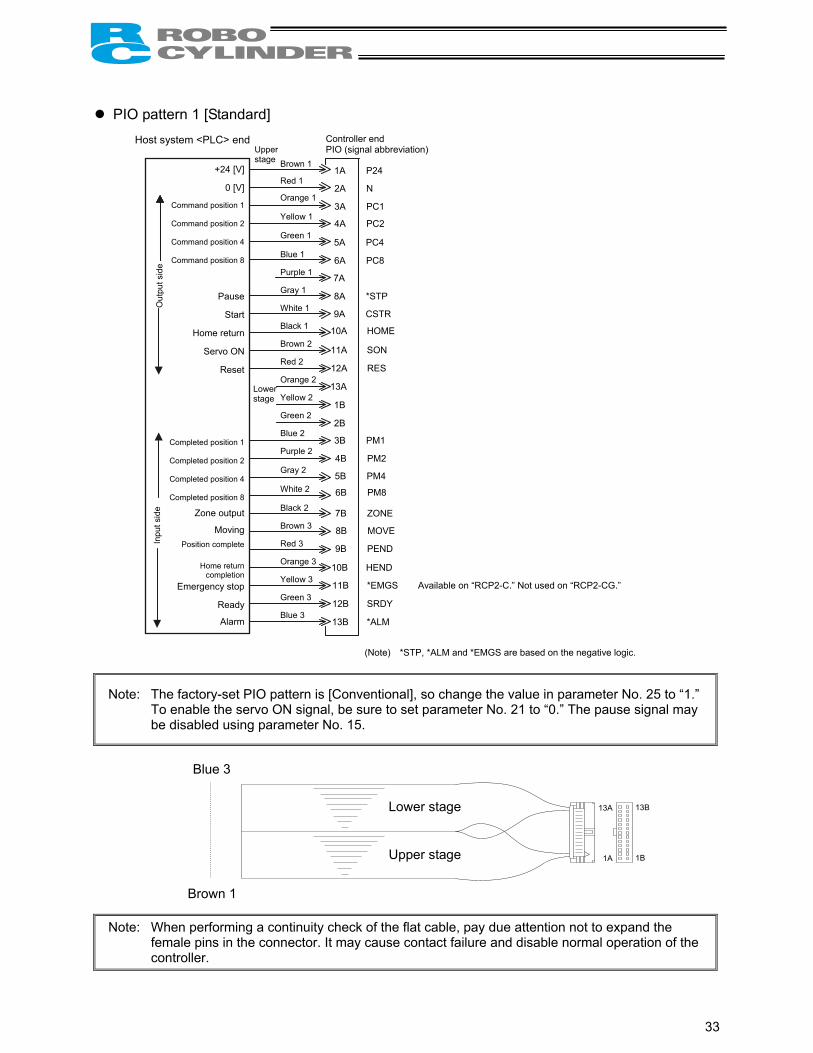
PIO pattern 1 [Standard]
Note: The factory-set PIO pattern is [Conventional], so change the value in parameter No. 25 to “1.” To enable the servo ON signal, be sure to set parameter No. 21 to “0.” The pause signal may
be disabled using parameter No. 15.
Note: When performing a continuity check of the flat cable, pay due attention not to expand the female pins in the connector. It may cause contact failure and disable normal operation of the controller.
1A P24
2A N
3A PC1
4A PC2
5A PC4
6A PC8
7A
8A *STP
9A CSTR
10A HOME
11A SON
12A RES
13A
1B
2B
3B PM1
4B PM2
5B PM4
6B PM8
7B ZONE
8B MOVE
9B PEND
10B HEND
11B *EMGS Available on “RCP2-C.” Not used on “RCP2-CG.”
12B SRDY
13B *ALM
Brown 1
Red 1
Orange 1
Yellow 1
Green 1
Blue 1
Purple 1
Gray 1
White 1
Black 1
Brown 2
Red 2
Orange 2
Yellow 2
Green 2
Blue 2
Purple 2
Gray 2
White 2
Black 2
Brown 3
Red 3
Orange 3
Yellow 3
Green 3
Blue 3
Controller end PIO (signal abbreviation)
Out
put s
ide
+24 [V]
0 [V]
Command position 1
Command position 2
Command position 4
Command position 8
Pause
Start
Home return
Servo ON
Reset
Completed position 1
Completed position 2
Completed position 4
Completed position 8
Zone output
MovingPosition complete
Home return completion
Emergency stop
Ready
Alarm
Inpu
t sid
e Upper stage
Lower stage
(Note) *STP, *ALM and *EMGS are based on the negative logic.
Host system <PLC> end
Lower stage
Upper stage
Blue 3
Brown 1
13A
1A
13B 1B

34
PIO pattern 2 [64-point positioning]
Note: The factory-set PIO pattern is [Conventional], so change the value in parameter No. 25 to “2.” The pause signal may be disabled using parameter No. 15.
Note: When performing a continuity check of the flat cable, pay due attention not to expand the female pins in the connector. It may cause contact failure and disable normal operation of the controller.
1A P24
2A N
3A PC1
4A PC2
5A PC4
6A PC8
7A PC16
8A PC32
9A CSTR
10A HOME
11A *STP
12A RES
13A
1B
2B
3B PM1
4B PM2
5B PM4
6B PM8
7B PM16
8B PM32
9B PEND
10B HEND
11B *EMGS Available on “RCP2-C.” Not used on “RCP2-CG.”
12B MOVE
13B *ALM
Brown 1
Red 1
Orange 1
Yellow 1
Green 1
Blue 1
Purple 1
Gray 1
White 1
Black 1
Brown 2
Red 2
Orange 2
Yellow 2
Green 2
Blue 2
Purple 2
Gray 2
White 2
Black 2
Brown 3
Red 3
Orange 3
Yellow 3
Green 3
Blue 3
Controller end PIO (signal abbreviation)
Out
put s
ide
+24 [V]
0 [V]
Command position 1
Command position 2
Command position 4
Command position 8
Command position 16
Command position 32
Start
Home return
Pause
Reset
Completed position 1
Completed position 2
Completed position 4
Completed position 8
Completed position 16
Completed position 32
Position completeHome return
completion
Emergency stop
Moving
Alarm
Inpu
t sid
e
Upper stage
Lower stage
(Note) *STP, *ALM and *EMGS are based on the negative logic.
Host system <PLC> end
Lower stage
Upper stage
Blue 3
Brown 1
13A
1A
13B 1B

35
PIO pattern 3 [2 zone output signals]
Note: The factory-set PIO pattern is [Conventional], so change the value in parameter No. 25 to “3.” To enable the servo ON signal, be sure to set parameter No. 21 to “0.” The pause signal may
be disabled using parameter No. 15.
Note: When performing a continuity check of the flat cable, pay due attention not to expand the female pins in the connector. It may cause contact failure and disable normal operation of the controller.
1A P24
2A N
3A PC1
4A PC2
5A PC4
6A PC8
7A
8A *STP
9A CSTR
10A HOME
11A SON
12A RES
13A
1B
2B
3B PM1
4B PM2
5B PM4
6B PM8
7B ZONE1
8B ZONE2
9B PEND
10B HEND
11B *EMGS Available on “RCP2-C.” Not used on “RCP2-CG.”
12B SRDY
13B *ALM
Brown 1
Red 1
Orange 1
Yellow 1
Green 1
Blue 1
Purple 1
Gray 1
White 1
Black 1
Brown 2
Red 2
Orange 2
Yellow 2
Green 2
Blue 2
Purple 2
Gray 2
White 2
Black 2
Brown 3
Red 3
Orange 3
Yellow 3
Green 3
Blue 3
Controller end PIO (signal abbreviation)
Out
put s
ide
+24 [V]
0 [V]
Command position 1
Command position 2
Command position 4
Command position 8
Pause
Start
Home return
Servo ON
Reset
Completed position 1
Completed position 2
Completed position 4
Completed position 8
Zone output 1
Zone output 2
Position completeHome return
completionEmergency stop
Ready
Alarm
Inpu
t sid
e
Upper stage
Lower stage
(Note) *STP, *ALM and *EMGS are based on the negative logic.
Host system <PLC> end
Lower stage
Upper stage
Blue 3
Brown 1
13A
1A
13B 1B

36
PIO pattern 4 [Teaching]
Note: The factory-set PIO pattern is [Conventional], so change the value in parameter No. 25 to “4.” To enable the servo ON signal, be sure to set parameter No. 21 to “0.” Be sure to enable the pause signal using parameter No. 15 (by setting the parameter to “0”)
(the pause signal is enabled at the factory). The system cannot switch to the teaching mode if the pause signal is disabled (i.e., the above parameter is set to “1”).
Note: When performing a continuity check of the flat cable, pay due attention not to expand the female pins in the connector. It may cause contact failure and disable normal operation of the controller.
1A P24
2A N
3A PC1
4A PC2
5A PC4
6A PC8
7A MODE
8A *STP/JOG +
9A CSTR/PWRT
10A HOME
11A SON
12A RES/JOG -
13A
1B
2B
3B PM1
4B PM2
5B PM4
6B PM8
7B MODES
8B MOVE
9B PEND/WEND
10B HEND
11B *EMGS Available on “RCP2-C.” Not used on “RCP2-CG.”
12B SRDY
13B *ALM
Brown 1
Red 1
Orange 1
Yellow 1
Green 1
Blue 1
Purple 1
Gray 1
White 1
Black 1
Brown 2
Red 2
Orange 2
Yellow 2
Green 2
Blue 2
Purple 2
Gray 2
White 2
Black 2
Brown 3
Red 3
Orange 3
Yellow 3
Green 3
Blue 3
Controller end PIO (signal abbreviation)
Out
put s
ide
+24 [V]
0 [V]
Command position 1
Command position 2
Command position 4
Command position 8
Operation mode
Pause/+Jog
Start/Position write
Home return
Servo ON
Reset/–Jog
Completed position 1
Completed position 2
Completed position 4
Completed position 8
Current operation mode
Moving Position complete/
Write completion Home return
completion Emergency stop
Ready
Alarm
Inpu
t sid
e
Upper stage
Lower stage
(Note) *STP, *ALM and *EMGS are based on the negative logic.
Host system <PLC> end
Lower stage
Upper stage
Blue 3
Brown 1
13A
1A
13B 1B

37
PIO pattern 5 [4 points] (air cylinder)
Note: The factory-set PIO pattern is [Conventional], so change the value in parameter No. 25 to “5.” The pause signal may be disabled using parameter No. 15.
Note: When performing a continuity check of the flat cable, pay due attention not to expand the female pins in the connector. It may cause contact failure and disable normal operation of the controller.
1A P24
2A N
3A ST0
4A ST1
5A ST2
6A ST3
7A
8A *STP
9A
10A
11A
12A RES
13A
1B
2B
3B PE0
4B PE1
5B PE2
6B PE3
7B ZONE
8B
9B PEND
10B HEND
11B *EMGS Available on “RCP2-C.” Not used on “RCP2-CG.”
12B
13B *ALM
Brown 1
Red 1
Orange 1
Yellow 1
Green 1
Blue 1
Purple 1
Gray 1
White 1
Black 1
Brown 2
Red 2
Orange 2
Yellow 2
Green 2
Blue 2
Purple 2
Gray 2
White 2
Black 2
Brown 3
Red 3
Orange 3
Yellow 3
Green 3
Blue 3
Controller end PIO (signal abbreviation)
Out
put s
ide
+24 [V]
0 [V]
Rear end move
Front end move Intermediate point
1 move Intermediate point
2 move
Pause
Reset
Rear end complete
Front end complete Intermediate point
1 complete Intermediate point
2 complete Zone output
Position complete
Home return completion
Emergency stop
Alarm
Inpu
t sid
e
Upper stage
Lower stage
(Note) *STP, *ALM and *EMGS are based on the negative logic.
Host system <PLC> end
Lower stage
Upper stage
Blue 3
Brown 1
13A
1A
13B 1B
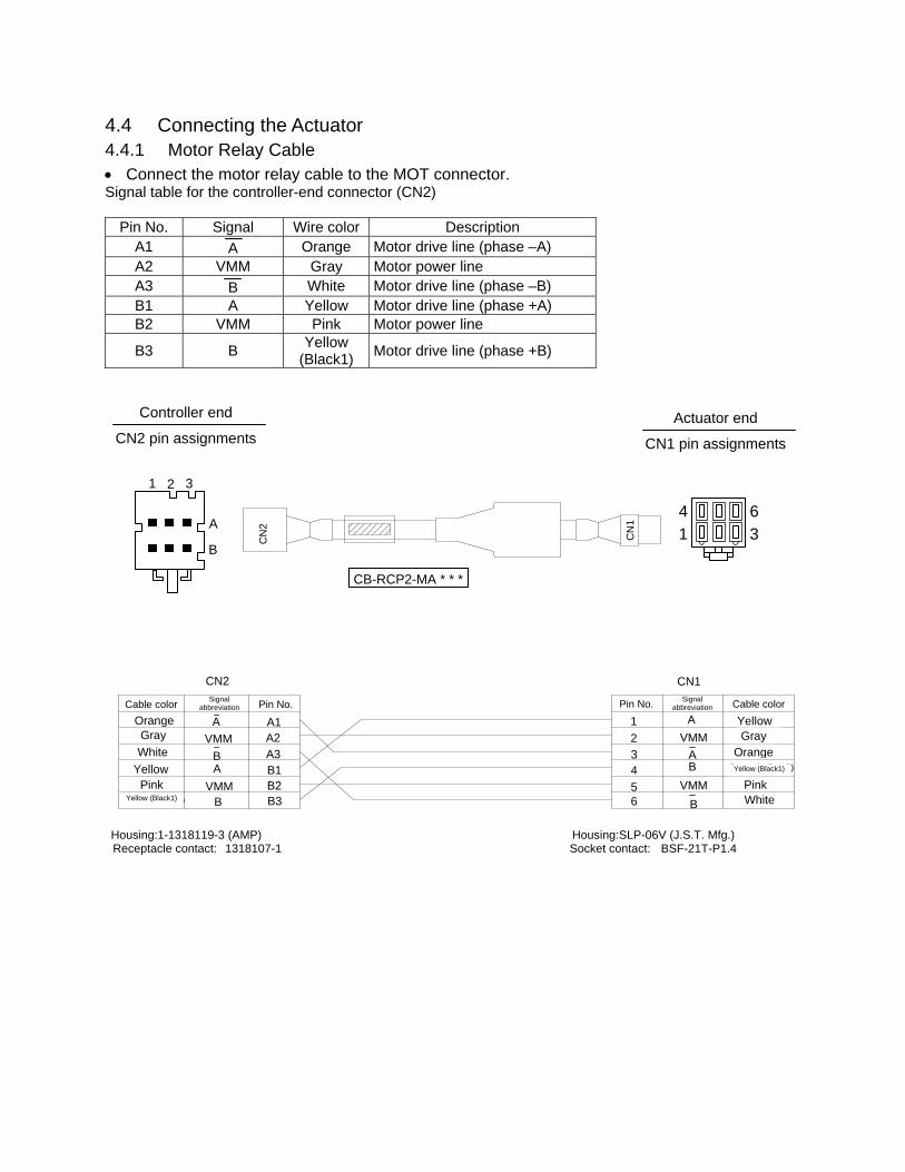
4.4 Connecting the Actuator 4.4.1 Motor Relay Cable • Connect the motor relay cable to the MOT connector. Signal table for the controller-end connector (CN2)
Pin No. Signal Wire color Description A1 A Orange Motor drive line (phase –A) A2 VMM Gray Motor power line A3 B White Motor drive line (phase –B) B1 A Yellow Motor drive line (phase +A) B2 VMM Pink Motor power line
B3 B Yellow (Black1) Motor drive line (phase +B)
Housing:1-1318119-3 (AMP) Housing:SLP-06V (J.S.T. Mfg.) Receptacle contact: 1318107-1 Socket contact: BSF-21T-P1.4
41
63
2 1 3
A
B
CN
2
CN
1
CB-RCP2-MA * * *
Blue Black White Red Black
Green (yellow 3)
A VMM
B A
VMM B
A1 A2 A3 B1 B2 B3
A VMM
A B
VMM B
1 2 3 4 5 6
Red BlackBlue
Green (yellow 3)
BlackWhite
Controller end
CN2 pin assignments Actuator end
CN1 pin assignments
CN2 CN1
Cable color Pin No. Pin No. Cable color Signal abbreviation
Signal abbreviation
Orange Gray
Yellow Pink
Yellow (Black1)
OrangeGray
Yellow
PinkYellow (Black1)

39
4.4.2 Encoder Relay Cable [Standard controller (2 A)]
• Connect the encoder relay cable to the ENC connector. Signal table for the controller-end connector (CN2)
Pin No. Signal abbreviation Description 1 F.G Shielded wire 2 - (Not used) 3 - (Not used) 4 - (Not used) 5 GND Encoder power output 6 5V 7 VPS Encoder control signal output 8 - (Reserved) 9 EN B Encoder differential signal phase-B input
10 EN B 11 EN A Encoder differential signal phase-A input 12 EN A 13 BK – Negative side of the brake power supply 14 BK + Positive side of the brake power supply 15 - (Reserved) 16 - (Reserved)
Cable colors and pin assignments for units shipped in and after August 2004 (supporting the absolute specification)
Housing: PHDR-16VS (J.S.T. Mfg.) Contact: SPHD-001T-P0.5 Housing: XMP-18V (J.S.T. Mfg.) Contact: BXA-001T-P0.6 Retainer: XMS-09V
1 2
15 16
CN
2
CN
1 CB-RCP2-PA * * *
Controller end
CN2 pin assignments Actuator end
CN1 pin assignments
CN2
CN1
Purple White (with purple)
Blue White (with blue)
Yellow White (with yellow)
-
-
- Green
- - -
BK + BK – ENA
ENA
ENB
5V GND
- - -
F.G
16 15 14 13 12 11 10 9 8 7 6 5 4 3 2 1
1 2 3 4 5 6 7 8 9 10 11 12 13 14 15 16 17 18
ENA ENA ENB ENB
GND5V
BK +BK –
F.G
- - - -
VPS- - - -
Red White (with red)
Drain
(Reserved)
(Reserved)
1 10
9 18
Cable color Pin No.
Robot cable Standard cable
- -
Red Gray
Brown Green Purple Pink
- Yellow Orange
Blue - - -
Drain
(Reserved)
Cable colorRobot cable
Blue White (with blue)
Yellow White (with yellow)
- - - -
White (with red)
Red Green
- - - -
Purple White (with purple)
Drain
Standard cable
Brown Green Purple Pink
- - - -
Blue Orange Yellow
- - - -
Red Gray Drain
Pin No.
VPS
CB-RCP2-PA * * *-RB
Standard cable
Robot cable
Signal abbreviation
Signal abbreviation
ENB

40
Reference: Cable colors and pin assignments for units shipped on or before July 31, 2004 Housing: PHDR-16VS (J.S.T. Mfg.) Contact: SPHD-001T-P0.5 Housing: XMP-18V (J.S.T. Mfg.) Contact: BXA-001T-P0.6 Retainer: XMS-09V
1 2
15 16
CN
2
CN
1
Controller end
CN2 pin assignments Actuator end
CN1 pin assignments
CN2
CN1
Light blue (red 1)
Light blue (black 1)
White (red 1) White (black 1)
Yellow (red 1) Yellow (black 1)
- -
-
- - -
BK + BK – ENA ENA ENB ENB
5V GND
- - -
F.G
16 15 14 13 12 11 10 9 8 7 6 5 4 3 2 1
1 2 3 4 5 6 7 8 9 10 11 12 13 14 15 16 17 18
ENA ENA ENB ENB
GND5V
BK +BK – F.G
- - - -
- - - - -
Orange (red 2) Orange (black 2)
Drain
(Reserved)
(Reserved)
1 10
9 18
Cable color Robot cable Standard cable
- -
Red Gray
Brown Green Purple Pink
- -
Orange Blue
- - -
Drain
(Reserved)
(Reserved)
Cable color Robot cable
White (red 1)
White (black 1)Yellow (red 1)Yellow (black 1)
- - - -
Orange (black 2)
Orange (red 2)- - - - -
Light blue (red 1)
Light blue (black 1)
Drain
Standard cable
Brown Green Purple Pink
- - - -
Blue Orange
- - - - -
Red Gray Drain
-
CB-RCP2-PA * * *
CB-RCP2-PA * * *-RB
Standard cable
Robot cable
Signal abbreviation
Signal abbreviation
Pin No.
Pin No.

41
[Large-capacity controller (6 A)] • Connect the encoder relay cable to the ENC connector. Signal table for the controller-end connector (CN2)
Pin No. Signal abbreviation Description 1 F.G Shielded wire 2 - (Not used) 3 - (Not used) 4 5V Encoder power output 5 GND 6 - (Not used) 7 VPS Encoder control signal output 8 - (Reserved) 9 EN B Encoder differential signal phase-B input
10 EN B 11 EN A Encoder differential signal phase-A input 12 EN A 13 BK – Negative side of the brake power supply 14 BK + Positive side of the brake power supply 15 - (Reserved) 16 - (Reserved)
Housing: PHDR-16VS (J.S.T. Mfg.) Contact: SPHD-001T-P0.5 Housing: XMP-18V (J.S.T. Mfg.) Contact: BXA-001T-P0.6 Retainer: XMS-09V
Controller end
CN2 pin assignments Actuator end
CN1 pin assignments
Purple
White (with purple)
Blue White (with blue)
Yellow White (with yellow)
Green
Red White (with red)
Drain
(Reserved)
(Reserved)
Cable color
Red Gray
Brown Green Purple Pink
Yellow
Blue
Orange
(Reserved)
Cable colorRobot cable
Blue
White (with blue)
Yellow White (with yellow)
Standard cable
Brown Green Purple Pink
Drain
Blue
Yellow Orange
Red Gray Drain
Green Red
Purple White (with purple)
Drain
White (with red)
Standard cableRobot cable
Robot cable Standard cable Signal
abbreviation
Signal abbreviation
Pin No.
Pin No.

42
4.5 Connecting the Communication Cable Connect the communication cable to the SIO connector.
1 2 36 8
5
Pin assignments of the cable-end connector
RS485 conversion adapter end Controller end
CB-RCA-SIO * * *
Brown 5V 1
Yellow
Red
Orange
Blue
Green
SGA
GND
SGB
GND
5V
2
3
4
5
6
Pin No.
SGA
SGB
5V EMGS
EMGA 24V
Brown/Green
1
2
3
4
5 6
Pin No.
7 8
Yellow
Orange
Black
Red/Blue GND
EMGB FG
Black
-
-
Cable color Cable color
Shielded
Shorting wire UL1004AWG28 (black)
Shielded, not connected
Signal abbreviation
Signal abbreviation

43
5. I/O Signal Control and Signal Functions 5.1 PIO Patterns and Signal Assignments This controller provides six PIO (Parallel I/O) patterns to meet the needs of various applications. To select a desired PIO pattern, set a corresponding value from 0 to 5 in parameter No. 25 (PIO pattern selection). The features of each PIO pattern are explained below:
Parameter No. 25 setting Feature of PIO pattern
0 Conventional This pattern is compatible with the pin assignments of the RCP controller.
1 Standard All functions of the RCP controller are available, plus the home-return command input, servo ON input, reset input, moving output and ready output.
2 64-point positioning Compared with the standard pattern offering only 16 positioning points, this pattern provides up to 64 positioning points. However, the servo ON input, ready output and zone output have been removed.
3 2 zone output signals Compared with the standard pattern offering only one zone output signal, this pattern provides two zone output signals. However, the moving output has been removed. The boundaries for the second zone output signal are specified in parameter Nos. 23 and 24.
4 Teaching This pattern allows for normal positioning operation, as well as jogging and writing of current position to a specified position using I/Os. Switching between the normal positioning mode and teaching mode is effected by the MODE input signal. The mode switching completion output has been added to indicate that the modes have been switched. However, the zone output has been removed. (Note) Position data can be rewritten up to around 100,000 times.
5 4 points (air cylinder) Use of the RCP2 as an air cylinder is assumed in this pattern. The number of positioning points is limited to four, but a direct command input and a position complete output are provided for each target position in line with the conventional practice of air cylinder control. This lets the user control the RCP2 just like an air cylinder.
Quick reference table for functions available under each PIO pattern ( --- Available, X --- Not available)
Input signals Output signals No. 25
Number of positioning
points
Number of zone output
signals Home return Servo ON Reset Jog Write Moving Ready
0 16 points 1 signal X X X X X X X 1 16 points 1 signal X X 2 64 points None X X X X 3 16 points 2 signals X X X 4 16 points None 5 4 points 1 signal X X X X X X
For details, refer to 5.1.2, “Signal Assignment Table for Respective PIO Patterns.”
Note: The servo ON input signal (SON) is not available if the conventional, 64-point or 4-point positioning pattern is selected.
Therefore, always set parameter No. 21 (Servo ON disable selection) to “1: [Disable]” when the controller is used in either of these PIO patterns.

44
5.1.1 Explanation of Signal Names The following explains the signal names, and gives a function overview of each signal. In the explanation of operation timings provided in a later section, each signal is referenced by its self-explanatory name for clarity. If necessary, however, such as when marker tubes are inserted as a termination of the flat cable, use the signal abbreviations.
PIO pattern = “0: [Conventional],” “1: [Standard],” “2: [64-point positioning],” “3: [2 zone output signals]”
Category Signal name Signal abbreviation Function overview
Start CSTR Movement is started at a rise edge of this signal.
Command position number PC1 PC2 PC4 PC8 PC16 PC32
The target position number is input. A command position number must be specified by 6 ms before the start signal (CSTR) turns ON.
*Pause *STP ON: Actuator can be moved, OFF: Actuator decelerates to a stop
Home return HOME The actuator moves in the positive direction while this signal is ON.
Servo ON SON The servo remains ON while this signal is ON. The servo remains OFF while this signal is OFF.
Input
Alarm reset RES An alarm is reset at a rise edge of this signal.
Completed position number PM1 PM2 PM4 PM8 PM16 PM32
The relevant position number is output when positioning has completed. The signal will turn OFF when the next start signal is received. It is used by the PLC to check if the commanded position has definitively been reached, and also to provide a position interlock, etc.
Moving MOVE This signal turns ON while the actuator is moving, and turns OFF while it is stopped. It is used for operation check and also to determine whether the load is contacted during push & hold operation.
Position complete PEND This signal turns ON when the target position was reached and the actuator has entered the specified in-position range. It is used to determine whether positioning has completed.
Home return completion HEND This signal is OFF immediately after the power is input, and turns ON when home return has completed.
Zone ZONE1 ZONE2
This signal is output when home return has completed and the current actuator position is inside the range set by the applicable parameter. It can be used as a limit switch at an intermediate point or as a simple ruler during push & hold operation.
Ready SRDY This signal is always output once the servo is turned ON and the controller is ready to operate. The signal is synchronized with the lit/unlit status of the “RUN” LED on the front panel of the enclosure. It is used by the PLC to determine when it can start operation.
*Alarm *ALM This signal remains ON in normal conditions of use and turns OFF when an alarm generates.
Output
*Emergency stop *EMGS This signal is enabled on a “built-in cutoff relay” controller. OFF: Emergency stop has been actuated

45
PIO pattern = “4: [Teaching]”
Category Signal name Signal abbreviation Function overview
Start CSTR Movement is started at a rise edge of this signal.
Command position number
PC1 PC2 PC4 PC8
The target position number is input. A command position number must be specified by 6 ms before the start signal (CSTR) turns ON.
*Pause *STP ON: Actuator can be moved, OFF: Actuator decelerates to a stop
Home return HOME Home return operation is started at a rise edge of this signal.
Operation mode MODE ON: Teaching mode, OFF: Normal mode
Current-position write PWRT When this signal has remained ON for 20 msec or longer, the current position will be stored under the position number selected by PC1 to PC8.
+Jog JOG+ The actuator moves in the positive direction while this signal is ON.
–Jog JOG- The actuator moves in the negative direction while this signal is ON.
Servo ON SON The servo remains ON while this signal is ON. The servo remains OFF while this signal is OFF.
Input
Alarm reset RES An alarm is reset at a rise edge of this signal.
Completed position number
PM1 PM2 PM4 PM8
The relevant position number is output when positioning has completed. The signal will turn OFF when the next start signal is received. It is used by the PLC to check if the commanded position has definitively been reached, and also to provide a position interlock, etc.
Moving MOVE This signal turns ON while the actuator is moving, and turns OFF while it is stopped. It is used for operation check and also to determine whether the load is contacted during push & hold operation.
Position complete PEND This signal turns ON when the target position was reached and the actuator has entered the specified in-position range. It is used to determine whether positioning has completed.
Home return completion HEND This signal is OFF immediately after the power is input, and turns ON when home return has completed.
Current operation mode MODES Currently enabled mode (ON: Teaching mode, OFF: Normal mode)
Write completion WEND This signal is output upon completion of writing to the nonvolatile memory in response to a current-position write command (PWRT).
Ready SRDY This signal is always output once the servo is turned ON and the controller is ready to operate. The signal is synchronized with the lit/unlit status of the “RUN” LED on the front panel of the enclosure. It is used by the PLC to determine when it can start operation.
*Alarm *ALM This signal remains ON in normal conditions of use and turns OFF when an alarm generates.
Output
*Emergency stop *EMGS This signal is enabled on a “built-in cutoff relay” controller. OFF: Emergency stop has been actuated

46
PIO pattern = “5: [4 points]
Category Signal name Signal abbreviation Function overview
Rear end move ST0 The actuator starts moving to the rear end at the rise edge of the signal.
Front end move ST1 The actuator starts moving to the front end at the rise edge of the signal.
Intermediate point 1 move ST2 The actuator starts moving to intermediate point 1 at the rise edge of the signal.
Intermediate point 2 move ST3 The actuator starts moving to intermediate point 2 at the rise edge of the signal.
*Pause *STP ON: Actuator can be moved, OFF: Actuator decelerates to a stop
Input
Alarm reset RES An alarm is reset at a rise edge of this signal.
Rear end complete PE0 The signal turns ON when the actuator completes moving to the rear end.
Front end complete PE1 The signal turns ON when the actuator completes moving to the front end.
Intermediate point 1 complete
PE2 The signal turns ON when the actuator completes moving to intermediate point 1.
Intermediate point 2 complete
PE2 The signal turns ON when the actuator completes moving to intermediate point 2.
Zone ZONE1 This signal is output when home return has completed and the current actuator position is inside the range set by the applicable parameter. It can be used as a limit switch at an intermediate point or as a simple ruler during push & hold operation.
Position complete PEND This signal is used to determine if the controller is ready following the power on. The controller is ready to perform operation if an emergency stop is not actuated, motor drive power is not cut off (= the servo is on) and the pause signal is input.
Home return completion HEND This signal is OFF immediately after the power is input, and turns ON when home return has completed.
*Alarm *ALM This signal remains ON in normal conditions of use and turns OFF when an alarm generates.
Output
*Emergency stop *EMGS This signal is enabled on a “built-in cutoff relay” controller. OFF: Emergency stop has been actuated

47
5.1.2 Signal Assignment Table for Respective PIO Patterns The same signal may be assigned to a different pin number depending on the PIO pattern. Therefore, when creating a PLC sequence or wiring the signals, refer to this table to ensure each signal is assigned correctly. When “4: [Teaching]” is selected, the meaning of each pin number will vary depending on the mode. Accordingly, also pay due attention to when mode switching will occur.
Parameter No. 25 setting Pin No.
Category Wire color
0 1 2 3 4 5
1A +24V Upper stage Brown - 1 P24
2A 0V Red - 1 N 3A Orange - 1 CSTR PC1 PC1 PC1 PC1 ST0 4A Yellow - 1 PC1 PC2 PC2 PC2 PC2 ST1 5A Green - 1 PC2 PC4 PC4 PC4 PC4 ST2 6A Blue - 1 PC4 PC8 PC8 PC8 PC8 ST3 7A Purple - 1 PC8 - PC16 - MODE - 8A Gray - 1 - *STP PC32 *STP *STP/JOG + *STP 9A White - 1 - CSTR CSTR CSTR CSTR/PWRT - 10A Black - 1 *STP HOME HOME HOME HOME - 11A Brown - 2 - SON *STP SON SON - 12A
Input
Red - 2 - RES RES RES RES/JOG – RES 13A Orange - 2 (Not used)
1B Lower stage Yellow - 2 (Not used)
2B Green - 2 (Not used) 3B Blue - 2 PM1 PM1 PM1 PM1 PM1 PE0 4B Purple - 2 PM2 PM2 PM2 PM2 PM2 PE1 5B Gray - 2 PM4 PM4 PM4 PM4 PM4 PE2 6B White - 2 PM8 PM8 PM8 PM8 PM8 PE3 7B Black - 2 PEND ZONE1 PM16 ZONE1 MODES ZONE1 8B Brown - 3 HEND MOVE PM32 ZONE2 MOVE - 9B Red - 3 ZONE1 PEND PEND PEND PEND/WEND PEND 10B Orange - 3 *ALM HEND HEND HEND HEND HEND 11B Yellow - 3 *EMGS 12B Green - 3 - SRDY MOVE SRDY SRDY - 13B
Output
Blue - 3 - *ALM *ALM *ALM *ALM *ALM
Note: [1] The signals indicated by * in the table (*ALM, *STP and *EMGS) are based on the negative
logic, meaning that they remain ON in normal conditions of use. [2] Insulate the pins indicated “Not used” (13A, 1B and 2B) without connecting anything. [3] The NPN and PNP specifications use the same power line configuration, so there is no need to
reverse the power signal assignments for a PNP controller. [4] *EMGS (emergency-stop state) assigned to pin No. 11B is enabled on a “built-in cutoff relay”
controller.

48
5.2 Interface Circuit The standard interface specification of the controller is NPN, but the PNP specification is also available as an option. To prevent confusion during wiring, the NPN and PNP specifications use the same power line configuration. Accordingly, there is no need to reverse the power signal assignments for a PNP controller. 5.2.1 External Input Specifications
Item Specification Number of input points 10 points
Input voltage 24 VDC ± 10% Input current 7 mA/point Leak current 1 mA or less/point
Insulation method Photocoupler Internal circuit configuration
[NPN specification]
[PNP specification]
P24V
R = 560 Ω
R = 3.3 kΩ
R = 22 kΩ
C = 0.1 µF
N
R = 560 Ω
R = 3.3 kΩ
R = 22 kΩ
C = 0.1 µF
Controller
Controller
External power supply +24V
Each input
External power supply +24V
Each input
Internal circuit
Internal circuit

49
5.2.2 External Output Specifications
Item Specification Number of output points 10 points
Rated load voltage 24 VDC Maximum current 20 mA/point Residual voltage 2 V or less Insulation method Photocoupler
Internal circuit configuration
[NPN specification]
[PNP specification]
N
P24V
N
P24V
Controller
External power supply +24V
Internal circuit Each output
Load
Load
Controller
External power supply +24V
Internal circuit
Each outputLoad
Load

50
5.3 Details of I/O Signal Functions An input time constant is provided for the input signals of this controller, in order to prevent malfunction due to chattering, noise, etc. Except for certain signals, switching of each input signal will be effected when the signal has been received continuously for at least 6 msec. For example, when an input is switched from OFF to ON, the controller will only recognize that the input signal is ON after 6 msec. The same applies to switching of input signals from ON to OFF (Fig. 1).
Fig. 1 Recognition of Input Signal 5.3.1. Details of Each Input Signal
Start (CSTR) Upon detecting a rise (OFF → ON) edge of this signal, the controller will read the target point number as a binary code consisting of four bits from PC1 to PC8 (or six bits from PC1 to PC32 in the 64-point positioning pattern), and execute positioning to the target position of the corresponding position data. Before issuing a start command, all operation parameters such as the target position and speed must be set in the nonvolatile memory of the controller. If a start command is issued when home return operation has not been performed yet after the power was input (the HEND output signal is OFF), the controller will automatically perform home return operation before positioning to the target position.
Command position number (PC1 to PC32) When a movement command is effected upon OFF → ON of the start signal, the six-bit binary code consisting of signals PC1 to PC32 will be read as the command position number. (Only with an expanded controller the binary code consists of six bits from PC1 to PC32. The binary code for all other controller types consists of four bits from PC1 to PC8.) The weight of each bit is as follows: 20 for PC1, 21 for PC2, 22 for PC4, 23 for PC8, 24 for PC16 and 25 for PC32. A desired position number from 0 to 63 (maximum) can be specified.
Pause (*STP) When this signal turns OFF while the actuator is moving, the actuator will decelerate to a stop. The remaining movement is retained and will be resumed when the signal is turned ON again. To abort the movement command, turn ON the alarm reset signal while this signal is OFF to cancel the remaining movement. The *STP signal can be used for the following purposes: [1] Provide a low-level safety measure to stop the axis while the servo is ON, such as a sensor that
detects a person approaching the system [2] Prevent contact with other equipment [3] Perform positioning based on sensor or LS detection (Note) If the *STP signal is input while the actuator is performing home return, the movement command
will be retained if the actuator is yet to contact a mechanical end. If the signal is input after the actuator has reversed upon contacting a mechanical end, home return will be performed again from the beginning.
6 [msec] 6 [msec]
Input signal
Recognition by controller
Not recognized Not recognized

51
Home return (HOME) The controller will start home return operation upon detection of an OFF → ON edge of this signal. When the home return is complete, the HEND signal will be output. The HOME signal can be input as many times as required. (Note) The HOME signal is not an absolute requirement, because even if home return has not yet been
performed after the power was input, the controller will automatically perform home return operation before positioning to the target position.
Setting “0.00 mm” as the position data will allow for movement to the home. Still, the HOME signal is convenient when there is no space in the position-data table or when the controller is used in the teaching mode.
Servo ON (SON)
The servo remains ON while this signal is ON. Use this signal if servo ON/OFF control must be performed by the PLC as part of a safety circuit covering the entire system. Parameter No. 21 that defines whether to enable or disable this signal must always be set. Set “0: [Enable]” if the SON signal is used, or “1: [Disable]” if the signal is not used. (Note) If the SON signal is turned OFF during movement in case of error, the actuator will decelerate to
a stop at the emergency-stop torque and then the servo will turn OFF.
Alarm reset (RES) This signal provides two functions.
[1] Reset the alarm output signal (*ALM) that turned OFF due to an alarm If an alarm has generated, turn ON this signal after confirming the nature of the alarm. The controller will reset the alarm upon detection of a rise edge of the RES signal.
(Note) Certain alarms cannot be reset by the RES signal. For details, refer to 10, “Troubleshooting.”
[2] Cancel the remaining movement when the pause signal is OFF This function is used when the remaining movement must be cancelled to allow for incremental moves (movements at a constant increment) from the position where the actuator stopped following a sensor detection.
Operation mode (MODE)
This signal is enabled when parameter No. 25 is set to “4: [Teaching].” Turning the MODE signal ON will switch the normal operation mode to the teaching mode. (Note) For the mode switching to occur, all of the *STP, CSTR and RES input signals must be OFF.
Once the mode switches, the MODES output signal will turn ON. Configure the system in such a way that the PLC will accept a PWRT, JOG+ or JOG- operation command after confirming the ON status of the MODES output signal. Turn the MODE signal OFF to return to the normal operation mode. Configure the system in such a way that the PLC will accept a command in the normal operation mode after confirming the OFF status of the MODES output signal.
(Note) The normal operation mode cannot be restored unless all of the PWRT, JOG+ and JOG- input signals are OFF.

52
Current-position write (PWRT) This signal is enabled when the aforementioned MODES output signal is ON. If the PWRT signal has remained ON for 20 msec or longer, the controller will read the position number specified by the currently detected binary code consisting of PC1 to PC8, and write the current position data as the target position in the corresponding position data. If data other than the target position (speed, acceleration/deceleration, positioning band, etc.) are yet to be defined, the default parameter settings will be written. When the writing completes successfully, the WEND output signal will turn ON. Configure the system in such a way that the PLC will turn OFF the PWRT signal when WEND turns ON. The controller will turn OFF WEND once the PWRT signal turns OFF. (Note) An alarm will generate if a write command is issued when home return has not been performed
yet or while the actuator is moving.
• Condition for PWRT to be enabled when the servo is ON: The PWRT signal is enabled when both the JOG+ and JOG- input signals are OFF, HEND output signal is ON and MOVE output signal is OFF.
• Condition for PWRT to be enabled when the servo is OFF: The PWRT signal is enabled when the HEND output signal is ON, but whether the actuator is being moved by hand or stopped cannot be determined from HEND alone. Input the PWRT signal when the operation is stopped.
Jog (JOG+, JOG-)
These signals are enabled when the aforementioned MODES output signal is ON. The controller will move the actuator to the +/- soft limit upon detection of a rise (OFF → ON) edge of each JOG signal. When the soft limit is reached, the actuator will be forced to decelerate to a stop without generating an alarm. The speed and acceleration/deceleration set in parameter No. 26 (PIO jog speed) and No. 9 (Default acceleration/deceleration) will be used. The actuator will not move if both the JOG+ and JOG- signals are turned ON. If both signals are turned ON while the actuator is moving, the actuator will decelerate to a stop. The controller will decelerate the actuator to a stop upon detection of a fall (ON → OFF) edge of each JOG signal. (Note) Executing jogging before home return is completed may disable the soft limits and cause the
actuator to crash into a mechanical end, so exercise due caution.
Movement to each position (ST0 to ST3) The number of positioning points is limited to four, so the RCP2 can be controlled just like an air cylinder. When the OFF ON rise edge of each movement signal is detected, the actuator will move to the target position corresponding to the applicable position data. Before executing a command using any of these signals, make sure the target position, speed and other operation data are set in the position table using a PC or teaching pendant.
Corresponding position number Remarks
Rear end move (ST0) 0 Set the rear end position in position No. 0.
Front end move (ST1) 1 Set the front end position in position No. 1.
Intermediate point 1 move (ST2) 2 Set the position of intermediate point 1 in position No. 2.
Intermediate point 2 move (ST3) 3 Set the position of intermediate point 2 in position No. 3. If a movement command is issued when the first home return is not yet completed after the power was input, home return will be performed automatically to establish the coordinates first, after which the actuator will move to the target position.

53
5.3.2 Details of Each Output Signal
Completed position number (PM1 to PM32) These signals can be used to check the completed position number when the PEND signal turns ON. The signals are output as a binary code. Immediately after the power is input, all of the PM1 to PM32 signals are OFF. (Only with an expanded controller the binary code consists of six bits from PM1 to PM32. The binary code for all other controller types consists of four bits from PM1 to PM8.) All of PM1 to PM32 are OFF also when the actuator is moving. As described above, this signal is output only when positioning is completed. (Note) All of PM1 to PM32 will turn OFF when the servo is turned OFF or an emergency stop is
actuated. They will return to the ON status when the servo is turned ON again, provided that the current position is inside the in-position range with respect to the target position. If the current position is outside the range, the signals will remain OFF.
When the power is input, the PEND signal will turn ON. Since PM1 to PM32 are all OFF, this condition is the same as one achieved after positioning to position “0” is completed.
Check the position of position 0 after the movement command has completed.
If an alarm is present, the corresponding alarm code (abbreviated form) consisting of four bits from PM1 to PM8 will be output. The meanings of these signals vary between the normal condition and the alarm condition, so be careful not to use them wrongly in the sequence.
Moving (MOVE) This signal is output while the servo is ON and the actuator is moving (also during home return, push & hold operation or jogging). Use the MOVE signal together with the PEND signal to allow the PLC to determine the actuator status. The MOVE signal will turn OFF after positioning or home return is completed or a judgment is made during push & hold operation that the load is being contacted.
Position complete (PEND) This signal indicates that the target position was reached and positioning has completed. Use the PEND signal together with the MOVE signal to allow the PLC to determine the positioning status. When the controller becomes ready after the power was input and the servo has turned ON, this signal will turn ON if the position deviation is within the in-position range. Then, when a movement command is issued by turning ON the start signal, the PEND signal will turn OFF. It will turn ON again when the deviation from the target position falls within the in-position range. Once turned ON, the PEND signal will not turn OFF even when the position deviation subsequently exceeds the in-position range. (Note) If the start signal remains ON, the PEND signal will not turn OFF even when the deviation from
the target position falls within the in-position range: it will turn ON when the start signal turns OFF.
Even when the motor is stopped, the PEND signal will remain OFF if the pause signal is input or the servo is OFF.
Home return completion (HEND)
This signal is OFF immediately after the power is input, and turns ON in either of the following two conditions:
[1] Home return operation has completed with respect to the first movement command issued with the start signal.
[2] Home return operation has completed following an input of the home return signal.
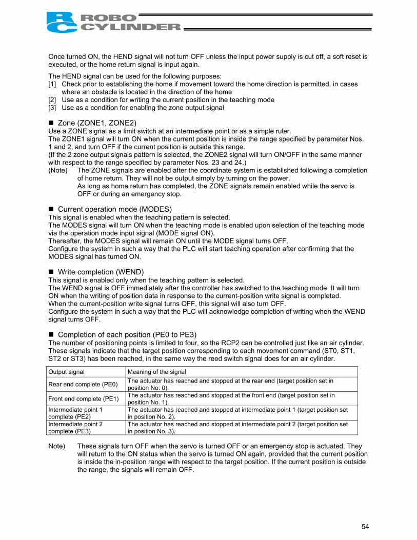
54
Once turned ON, the HEND signal will not turn OFF unless the input power supply is cut off, a soft reset is executed, or the home return signal is input again.
The HEND signal can be used for the following purposes: [1] Check prior to establishing the home if movement toward the home direction is permitted, in cases
where an obstacle is located in the direction of the home [2] Use as a condition for writing the current position in the teaching mode [3] Use as a condition for enabling the zone output signal
Zone (ZONE1, ZONE2) Use a ZONE signal as a limit switch at an intermediate point or as a simple ruler. The ZONE1 signal will turn ON when the current position is inside the range specified by parameter Nos. 1 and 2, and turn OFF if the current position is outside this range. (If the 2 zone output signals pattern is selected, the ZONE2 signal will turn ON/OFF in the same manner with respect to the range specified by parameter Nos. 23 and 24.) (Note) The ZONE signals are enabled after the coordinate system is established following a completion
of home return. They will not be output simply by turning on the power. As long as home return has completed, the ZONE signals remain enabled while the servo is
OFF or during an emergency stop.
Current operation mode (MODES) This signal is enabled when the teaching pattern is selected. The MODES signal will turn ON when the teaching mode is enabled upon selection of the teaching mode via the operation mode input signal (MODE signal ON). Thereafter, the MODES signal will remain ON until the MODE signal turns OFF. Configure the system in such a way that the PLC will start teaching operation after confirming that the MODES signal has turned ON.
Write completion (WEND) This signal is enabled only when the teaching pattern is selected. The WEND signal is OFF immediately after the controller has switched to the teaching mode. It will turn ON when the writing of position data in response to the current-position write signal is completed. When the current-position write signal turns OFF, this signal will also turn OFF. Configure the system in such a way that the PLC will acknowledge completion of writing when the WEND signal turns OFF.
Completion of each position (PE0 to PE3) The number of positioning points is limited to four, so the RCP2 can be controlled just like an air cylinder. These signals indicate that the target position corresponding to each movement command (ST0, ST1, ST2 or ST3) has been reached, in the same way the reed switch signal does for an air cylinder.
Output signal Meaning of the signal
Rear end complete (PE0) The actuator has reached and stopped at the rear end (target position set in position No. 0).
Front end complete (PE1) The actuator has reached and stopped at the front end (target position set in position No. 1).
Intermediate point 1 complete (PE2)
The actuator has reached and stopped at intermediate point 1 (target position set in position No. 2).
Intermediate point 2 complete (PE3)
The actuator has reached and stopped at intermediate point 2 (target position set in position No. 3).
Note) These signals turn OFF when the servo is turned OFF or an emergency stop is actuated. They
will return to the ON status when the servo is turned ON again, provided that the current position is inside the in-position range with respect to the target position. If the current position is outside the range, the signals will remain OFF.

55
Ready (SRDY) This is a monitor signal indicating that the servo is ON and the motor is ready. The ON/OFF status of the SRDY signal is synchronized with the lit/unlit status of the “RUN” LED on the front panel of the enclosure. Use this signal as a condition for starting a movement command on the PLC side. Refer to 7.1, “How to Start,” for the timing to issue this signal after the power is input.
Alarm (*ALM) This signal remains ON while the controller is operating properly, and turns OFF when an alarm has generated. Provide an appropriate safety measure for the entire system by allowing the PLC to monitor the OFF status of this signal. For details of alarms, refer to 10, “Troubleshooting.”
Emergency stop (*EMGS) This signal is enabled on a “built-in cutoff relay” controller. The *EMGS signal remains ON in normal conditions of use, and turns OFF when the emergency-stop switch has been pressed. Provide an appropriate safety measure for the entire system by allowing the PLC to monitor the OFF status of this signal. (Reference) Output Signal Changes in Each Mode
Mode classification MOVE PEND SRDY HEND PM1-PM8
Actuator is stopped with the servo ON after the power was input OFF ON ON OFF OFF
Home return is in progress following an input of the home return signal ON OFF ON OFF OFF
Home return has completed following an input of the home return signal OFF ON ON ON OFF
Actuator is moving in the positioning/push & hold mode ON OFF ON ON OFF
Actuator is paused in the positioning/push & hold mode OFF OFF ON ON OFF
Positioning has completed in the positioning mode OFF ON ON ON ON Actuator has stopped after contacting the load in the push & hold mode OFF ON ON ON ON
Actuator has stopped after missing the load (no load) in the push & hold mode OFF OFF ON ON ON
Actuator is stopped with the servo ON in the teaching mode OFF ON ON
Actuator is jogging in the teaching mode ON ON ON Actuator is being moved by hand with the servo OFF in the teaching mode OFF
OFF ON
Servo is OFF after home return OFF OFF OFF ON OFF
Emergency stop has been actuated after home return OFF OFF OFF ON
(Note) Determine whether the actuator has stopped after contacting the load or missing the load from the signal statuses of MOVE, PEND and PM1 to PM8.

56
6. Data Entry <Basics> This controller doesn’t use command words, so there is no need to create a program. All you need is to enter the target position in the position-data table, and the actuator will move to the specified position. Position data consists of number (No.), target position (Position), speed (Speed), acceleration/deceleration (ACC), push (Push), positioning band (Pos. band), and acceleration only MAX (ACC MAX). The description in parentheses is as displayed on the teaching pendant. The target position can be specified in two different modes: by absolute coordinate specification (absolute mode) in which the distance from the home is entered, or by relative coordinate specification (incremental mode) in which the incremental movement from the current position is entered.
Position-data table
No. Position Note Speed Acceleration/ deceleration Push Positioning
band Acceleration
only MAX 0 0 100 0.3 0 0.1 0 1 30 100 0.3 0 0.1 0 2 10 100 0.3 0 0.1 0
15
100
100
0.3
0
0.1
0
When data is entered in the position column of the position-data table, the default values will be automatically entered in the remaining columns. Change the default values as necessary. To change a default value, change the corresponding parameters starting with “Default.” The default values vary depending on the actuator type.
This indicates that the incremental mode is active. (This symbol is displayed only on the teaching pendant. Separate columns for incremental specification are provided in the PC software.)
Note: Enter position data first. Any attempt to enter other data before position data will be rejected. You can enter position data containing two decimal places. However, the controller only recognizes position data as a multiple of its minimum resolution. The minimum resolution of the controller varies depending on the actuator lead. For the above reason, the second decimal place in the entered position data may be rewritten
in accordance with the actuator lead. Example: Entered value Stored value 50.01 50.03
~ ~
~~
=
→

57
6.1 Description of Position-Data Table (1) No.
• Indicate the position data number. To enter an incremental movement, press the minus key in this column. On the teaching pendant, a “=” will be displayed between the number and position columns. The minus key need not be pressed in the absolute mode.
(2) Target position
(Position)
• Enter the target position to move the actuator to, in [mm]. Absolute mode: Enter the distance to the target actuator position from
the home. Incremental mode: Enter the distance to the target actuator position from
the current position. A negative value can also be entered (for movement in the negative direction along the displayed coordinate axis).
No. Position 0 30 Absolute mode 30 mm from the home 1 10 Incremental mode +10 mm from the current position 2 -10 Incremental mode -10 mm from the current position 3 100 Absolute mode 100 mm from the home
(3) Speed (Speed)
• Enter the speed at which the actuator will be moved, in [mm/sec]. The default value varies depending on the actuator type.
(4) Acceleration/ deceleration (ACC)
• Enter the acceleration/deceleration at which the actuator will be moved, in [G]. Basically, the acceleration should conform to the rating specified in the catalog. With this product, the acceleration can be raised to reduce the tact time, provided that the “actual payload is significantly smaller than the rated load capacity.” For this reason, the acceleration field in the position table permits entry of values greater than the rated acceleration.
Note: Enter appropriate speed and acceleration/deceleration by referring to Appendix, “List of Supported Actuator Specifications” and by also considering the installation condition and shape of load, so as to prevent the actuator from receiving excessive impact or vibration.
If you want to raise the speed or acceleration/deceleration, the payload and the characteristics of your specific actuator model must be considered. Contact IAI’s Sales Engineering Section for the maximum speed and acceleration/deceleration that can be entered for your specific application.
=
=
Speed
Acceleration/deceleration (ACC)
Start Completion Time
Acceleration/deceleration G --- MIN 0.01 G (Slow rise) MAX 0.9 G (Quick rise) (Varies depending on the model.)

58
(5) Push (Push)
• Select the positioning mode or push & hold mode. The default value is “0.” 0: Positioning mode (= Normal operation) Other than 0: Push & hold mode [%]
• In the push & hold mode, enter the current-limiting value for the pulse motor during push & hold operation.
Be sure to refer to 6.1.1, “Relationship of Push Force at Standstill and Current-Limiting Value” that specifies the relationship of the push force to be applied to the load at standstill [kgf] on one hand, and the current-limiting value on the other, for each actuator type.
Note: If the push force is too small, a false detection of push & hold condition may occur due to slide resistance, etc., so exercise caution.
(6) Positioning band (Pos. band)
• The function of the positioning band varies depending on whether the push & hold setting in (5) is “0” or “other than 0.”
(A) Push = 0 (Positioning mode) • In the positioning mode, enter the position-complete detection width
(distance to the target position), in [mm]. • The distance to the target position indicates the range prior to the target
position, upon entry of the actuator in which range a position complete signal will be output.
The default value is “0.1 [mm]” (Fig. A). (B) Push = Other than 0 (Push & hold mode) • Enter the maximum push amount (distance from the target) in the push
& hold mode, in [mm] (Fig. B). • If the push direction corresponds to the negative direction along the
displayed coordinate axis, add a – (minus) sign to the entered value.
Fig. A Fig. B
Spe
ed
Spe
ed [A] Push = 0
Distance to the position set in (2)
[B] Push = Other than 0
Distance to the position set in (2)
Moving distance Moving distance (6) Positioning band (6) Positioning band

59
(7) Acceleration only MAX
(ACC MAX) • Select the specified acceleration or maximum acceleration by entering
“0” or “1.” The default value is “0.”
0: Specified acceleration --- The value entered in (4) becomes the actual acceleration/deceleration.
1: Maximum acceleration --- The maximum acceleration. The deceleration conforms to the value entered in (4).
Note: Enable the acceleration only MAX setting when the actual payload is no more than one-third the rated load capacity.
Check the rated load capacity by referring to Appendix, “List of Supported Actuator Specifications.”
(7) Acceleration only MAX = 0 (7) Acceleration only MAX = 1
Acceleration/deceleration set in (4)
Acceleration/deceleration set in (4)
Maximum acceleration Spe
ed
Spe
ed
Moving distance Moving distance

60
6.1.1 Relationship of Push Force at Standstill and Current-Limiting Value When performing operation in the push & hold mode, enter the current-limiting value (%) in the push column of the position-data table. Determine the current-limiting value (%) from the push force to be applied to the load at standstill. The graphs below illustrate the relationship of push force at standstill and current-limiting value for each actuator type:
Slider type (1) SA5/SA6/SS type (2) SA7 type
Note: The accuracy of push force at standstill is not guaranteed. The above graphs are provided for reference purposes only. If the push force is too small, malfunction may occur during push & hold operation due to slide resistance, etc., so exercise caution.
The maximum current-limiting value is shown in the above graphs. The minimum value is 20%.
Low-speed type Low-speed type (Lead: 3 mm) (Lead: 4 mm)
Pus
h fo
rce
(N)
Pus
h fo
rce
(N)
Pus
h fo
rce
(N)
Current-limiting value (ratio in %) Current-limiting value (ratio in %)
Medium-speed type Medium-speed type (Lead: 6 mm) (Lead: 8 mm)
Pus
h fo
rce
(N)
Pus
h fo
rce
(N)
Pus
h fo
rce
(N)
High-speed type High-speed type (Lead: 12 mm) (Lead: 16 mm)
Current-limiting value (ratio in %) Current-limiting value (ratio in %)
Current-limiting value (ratio in %) Current-limiting value (ratio in %)

61
(3) SM type
Note: The accuracy of push force at standstill is not guaranteed. The above graphs are provided for reference purposes only. If the push force is too small, malfunction may occur during push & hold operation due to slide resistance, etc., so exercise caution.
The maximum current-limiting value is shown in the above graphs. The minimum value is 20%.
Low-speed type (Lead: 5 mm)
Pus
h fo
rce
(N)
Pus
h fo
rce
(N)
Pus
h fo
rce
(N)
Current-limiting value (ratio in %)
Medium-speed type (Lead: 10 mm)
High-speed type (Lead: 20 mm)
Current-limiting value (ratio in %)
Current-limiting value (ratio in %)

62
Rod type (1) RPA type (2) RXA type
Note: The accuracy of push force at standstill is not guaranteed. The above graphs are provided for reference purposes only. If the push force is too small, malfunction may occur during push & hold operation due to slide resistance, etc., so exercise caution.
The maximum current-limiting value is shown in the above graphs. The minimum value is 20%.
Low-speed type (Lead: 2.5 mm)
Pus
h fo
rce
(N)
Pus
h fo
rce
(N)
Current-limiting value (%) Current-limiting value (%)
Pus
h fo
rce
(N)
Current-limiting value (%)
Medium-speed type (Lead: 5 mm)

63
(3) RSA/RSW type (4) RMA/RMW type
Note: The accuracy of push force at standstill is not guaranteed. The above graphs are provided for reference purposes only. If the push force is too small, malfunction may occur during push & hold operation due to slide resistance, etc., so exercise caution.
The maximum current-limiting value is shown in the above graphs. The minimum value is 20%.
Pus
h fo
rce
(N)
Pus
h fo
rce
(N)
Current-limiting value (%) Current-limiting value (%)
Low-speed type Low-speed type (Lead: 2.5 mm) (Lead: 4 mm)
Medium-speed type Medium-speed type (Lead: 5 mm) (Lead: 8 mm)
High-speed type High-speed type (Lead: 10 mm) (Lead: 16 mm)
Current-limiting value (%) Current-limiting value (%)
Pus
h fo
rce
(N)
Pus
h fo
rce
(N)
Pus
h fo
rce
(N)
Pus
h fo
rce
(N)
Current-limiting value (%) Current-limiting value (%)

64
(5) RFA/RFW type
Note: The accuracy of push force at standstill is not guaranteed. The above graphs are provided for reference purposes only. If the push force is too small, malfunction may occur during push & hold operation due to slide resistance, etc., so exercise caution.
The maximum current-limiting value is shown in the above graphs. The minimum value is 20%.
Pus
h fo
rce
(N)
Current-limiting value (%)
Low-speed type (Lead: 2.5 mm)
Medium-speed type (Lead: 5 mm)
High-speed type (Lead: 10 mm)
Current-limiting value (%)
Pus
h fo
rce
(N)
Pus
h fo
rce
(N)
Current-limiting value (%)

65
6.2 Explanation of Modes 6.2.1 Positioning Mode Push = 0 6.2.2 Push & Hold Mode Push = Other than 0 (1) Load was contacted successfully
(1) After reaching the target position, the actuator will move at low speed.
When the Pos. band set in the data table (see Note) is reached after the actuator contacts the load and the stepper motor current has reached the current-limiting value, the position complete output will turn ON. A completed position number signal will be output at the same time.
Note: Set the parameter “Push & hold stop judgment period.” The default value of “255 [msec]” is already entered.
The actuator is holding the load in position while pushing it.
Warning The actuator continues to push the load at the push force at standstill determined by the current-limiting value. Since the actuator is not inactive, exercise due caution when handling the machine in this condition.
The push speed is set as follows in accordance with the speed set in the position-data table:
Set speed
20 mm/sec or more Less than 20 mm/sec Push speed 20 mm/sec Set speed
Position complete signal Completed position number
Output
(1) The position complete output will turn ON at a position preceding the target position by the positioning band. A completed position number signal will be output at the same time.
Spee
d
Moving distance Positioning band
Position complete signal Completed position number
Output Spee
d
Moving distance Positioning band

66
(2) Load was not contacted (missed)
(1) After reaching the target position, the actuator will move at low speed.
Even after contacting the load, the actuator will move to the end of the positioning band if the stepper motor current is yet to reach the current-limiting value.
The position complete output will not turn ON even when the end of the positioning band is reached. In this case, only the completed position number will be output. (Provide a timeout check process after a sufficient period with a PLC.)
(3) Load moves during push & hold operation
(a) Load moves in the pushed direction
If the load moves in the pushed direction after the position complete output has turned ON, the actuator will push the load within the positioning band.
If the current drops below the limiting value, the position complete signal will turn OFF. The signal will turn ON when the current rises to or above the limiting value.
(b) Load moves in the opposite direction (Actuator is pushed back by the reactive force of the load)
If the actuator is pushed back after the position complete output has turned ON because the actuator thrust is smaller than the reactive force of the load, the actuator will be pushed back all the way until its thrust balances out with the reactive force of the load. The position complete output will remain ON and the completed position number will be output continuously.
Spee
d
Moving distance Positioning band
Completed position number
Output
Spee
d
Moving distance
Positioning band
Position complete signal Completed position number
Output
Spee
d
Moving distance
Position complete signal Completed position number
Output

67
(4) Positioning band was entered with a wrong sign
If the positioning band is entered with a wrong sign, the position will deviate by twice the positioning band, as shown to the left, so exercise due caution.
6.2.3 Speed Change during Movement Speed control involving multiple speed levels is possible in a single operation. The actuator speed can be decreased or increased at a certain point during movement. However, the position at which to implement each speed change must be set. 6.2.4 Operation at Different Acceleration and Deceleration Settings The actuator will accelerate and decelerate at different speeds if “1” is entered under “Acceleration only MAX” in the position data. The acceleration conforms to the maximum acceleration. The deceleration conforms to the value entered under “Acceleration/deceleration” in the position data.
Note: Although the maximum acceleration varies depending on the actuator, the limit is three times the rated acceleration.
Therefore, enable the acceleration only MAX function only when the payload is no more than one-third the rated load capacity and you want to stop the actuator along a gradual deceleration curve.
Enabling this function when the payload is equivalent to the rated load capacity may generate an overload error.
Even when an overload error does not generate, the actuator may still receive an excessive impact load that shortens the life of the actuator. Therefore, exercise due caution when enabling the acceleration only MAX function.
Check the rated load capacity by referring to Appendix, “List of Supported Actuator Specifications.”
Spee
d
Moving distance Positioning
band Positioning
band
Position 1 Position 2 Position 1 Position 2 Position 1 Position 2 Position 3
Spee
d
Maximum acceleration Deceleration can be set freely
Time

68
6.2.5 Pause The actuator can be paused during movement using an external input signal (*pause). The pause signal uses the contact B logic (always ON) to ensure safety. Turning OFF the *pause input will cause the actuator to decelerate to a stop, while turning it ON will allow the actuator to complete the remaining operation. (Note) During deceleration, the acceleration/deceleration set in the position table under the currently
executed position number is used. The remaining movement of the actuator can be cancelled by turning ON the reset input during pause (the movement will be cancelled upon rise of the reset input signal). Note) If parameter No. 25 (IO pattern) is set to “0: [Conventional],” the reset input is not available.
ON ON
OFF *Pause signal
Actuator operation
*Pause signal
Reset
Actuator operation
Target position

69
6.2.6 Zone Signal Output A signal will be output when the actuator enters the specified zone. The zone signal will turn ON when the actuator enters the zone predefined by the applicable parameters. (The zone can be set arbitrarily.) If parameter No. 25 is set to “3: [2 zone output signals],” two zone output signals can be set. The second zone value is set by parameter No. 23 (Zone 2+) and No. 24 (Zone 2-). Note) The zone signal output function is not available if parameter No. 25 (PIO pattern) is set to “2: [64-
point positioning]” or “4: [Teaching].” 6.2.7 Home Return (1) On the standard controller, home return must be executed after the power is turned on to establish
the home. (2) On the absolute controller, home return is not required when the power is turned on. This is because
once home return is executed, the current position will be retained even after the power is turned off. On the absolute controller, home return is required only after the controller is started for the first time
or when the current position has been lost due to low battery voltage, etc. There are two ways to execute home return.
Not using the dedicated input [PIO pattern = 0 (Conventional) or 5 (4 points)] If home return has not been executed yet, inputting a command position followed by the start signal will execute home return.
Using the dedicated input [PIO pattern = Other than 0 (Conventional) or 5 (4 points)]
Inputting the home return signal (HOME) will execute home return regardless of whether the home position has already been established or nor.
For details, refer to 7.2, “How to Execute Home Return.”
Zone signal
Zone signal setting range
Actuator operation

70
6.2.8 Teaching Mode (Jogging/Teaching Using PIO) The actuator can be jogged using PIO if parameter No. 25 (PIO pattern) is set to “4: [Teaching].” The current actuator position can also be read into the controller’s position-data table using PIO. Switching between the normal positioning mode (including the push & hold mode) and the teaching mode is implemented by turning ON/OFF the operation mode input. Among the PIO signals, the +jog and *pause inputs, –jog and reset inputs, current-position write and start inputs, and write completion and position complete outputs use the same terminal, respectively, and are toggled in accordance with ON/OFF of the operation mode input.
Operation mode input ON OFF Mode Teaching mode Positioning mode
+Jog input *Pause input –Jog input Reset input
Current-position write input Start input PIO
Write completion output Position complete output Among the PIO signals, use the +jog/–jog inputs to move the actuator, and use the current-position write input to write the current actuator position to the position-data table. When the writing is complete, the write completion output will turn ON.
For details, refer to 7.12, “Jogging/Teaching Using PIO.”
Note: Be sure to enable the pause signal using parameter No. 15 (by setting the parameter to “0”) (the pause signal is enabled at the factory). The system cannot switch to the teaching mode if the pause signal is disabled (i.e., the above parameter is set to “1”).

71
6.2.9 Overview of the “4 Points” (Air Cylinder) Mode This mode provides a control method adjusted to that of an air cylinder by assuming that the RCP2 is used as an air cylinder. The key differences between the RCP2 and an air cylinder are summarized below. Perform proper control by referring to this table.
Item Air cylinder RCP2 Drive method Air pressure supplied via
electromagnetic valve control
Ball screw/timing belt driven by a motor
Target position setting
Mechanical stopper (including shock absorber)
Desired coordinates are entered in the [Target position] field of the position table. The coordinates can be typed in from the number keys on the PC keyboard or on the teaching pendant, or set directly by moving the actuator to the target position.
Target position detection
An external detection sensor, such as a reed switch, is installed.
Determined based on the internal coordinates provided by the position information from the position detector (encoder). Accordingly, external detection sensor is not required.
Speed setting Adjusted by a speed controller.
A desired feed speed is entered in the [Speed] field of the position table (unit: mm/sec). Note that the rated speed is automatically set as the initial value.
Acceleration/ deceleration setting
Determined in accordance with the load, supplied air volume, as well as the performance of the speed controller and electromagnetic valve.
A desired acceleration/deceleration is entered in the [Acceleration/deceleration] field of the position table (unit: 0.01 G). (Reference) 1 G = Gravitational acceleration Note that the rated acceleration/deceleration is automatically set as the initial value. Since the acceleration/deceleration can be set in fine steps, a gradual acceleration/deceleration curve can be programmed.
Position check upon power ON
Determined by an external detection sensor, such as a reed switch.
Immediately after the power is turned on, the controller cannot identify the current position because the mechanical coordinates have been lost. Therefore, when the first movement command is issued after the power has been input, the controller will automatically perform home return before moving the actuator to the target position. [1] The actuator moves at the home return speed toward the
mechanical end on the motor side. [2] The actuator hits the mechanical end and turns back, and
then stops temporarily at the home position. [3] The actuator moves to the target position at the speed
specified in the [Speed] field of the position table. (Note) Pay attention not to allow any obstacle in the travel
path of the actuator during home return.
[1]
[2]
[3] Home position
Target position
Power is turned on here.

72
The relationships of movement command inputs/position complete outputs and corresponding position numbers are shown below. For easier identification, each input/output signal has a name similar to the naming convention used with air cylinders. However, note that the target position is determined by the value set in the [Target position] field under each position number. Therefore, changing the magnitude correlation of the settings in Nos. 0 to 3 will change the meanings of the corresponding input/output signals. Accordingly, the settings in the respective position numbers should match the semantic meanings of the corresponding signal names used in this operation manual, unless doing so will pose a problem.
Input signal Output signal Target position
Rear end move (ST0) Rear end complete (PE0) Setting in the [Target position] field under position No. 0 Example: 5 mm
Front end move (ST1) Front end complete (PE1) Setting in the [Target position] field under position No. 1 Example: 390 mm
Intermediate point 1 move (ST2) Intermediate point 1 complete (PE2) Setting in the [Target position] field under position No. 2 Example: 100 mm
Intermediate point 2 move (ST3) Intermediate point 2 complete (PE3) Setting in the [Target position] field under position No. 3 Example: 250 mm
Positioning relationship on the ROBO Cylinder An example of a slider type with a stroke of 400 mm is explained.
[Motor side] [Counter-motor side]
Position table (Enter in the fields indicated in bold)
No. Position Speed Acceleration/ deceleration Push Positioning
band Acceleration
only MAX 0 5 500 0.3 0 0.1 0 1 390 500 0.3 0 0.1 0 2 100 500 0.3 0 0.1 0 3 250 500 0.3 0 0.1 0
Home position (0 mm)
Rear end complete (5 mm)
Front end complete (390 mm)
Intermediate point 2 complete (250 mm)
Intermediate point 1 complete (100 mm)

73
6.3 Notes on the ROBO Gripper (1) Finger operation
[1] Definition of position With the two-finger type, the stroke in the specification represents the sum of travels of both fingers. Therefore, the travel of one finger is one-half the stroke. The position is specified as a travel of one finger from the home toward the closing side. Accordingly, the maximum command value is 5 mm for the GRS type and 7 mm for the GRM type.
[2] Definition of speed and acceleration
The command value applies to each finger. With the two-finger type, therefore, the relative speed and acceleration are twice their respective command values.
[3] Operation mode in gripper applications
When the actuator is used to grip the load, be sure to select the “push & hold mode.” (Note) In the “positioning mode,” a servo error may occur while the load is gripped.
[Diagrams of gripping force and current-limiting value]
Current-limiting value (ratio in %) Current-limiting value (ratio in %)
Grip
ping
forc
e (N
)
Grip
ping
forc
e (N
)
Grip
ping
forc
e (N
)
Grip
ping
forc
e (N
)
Grip
ping
forc
e (N
)
Grip
ping
forc
e (N
)
Current-limiting value (ratio in %) Current-limiting value (ratio in %)
Current-limiting value (ratio in %) Current-limiting value (ratio in %)

74
(2) Removing the gripped load This gripper is designed to maintain the load-gripping force via a self-lock mechanism even when the
servo is turned OFF or the controller power is cut off. If the gripped load must be removed while the power is cut off, do so by turning the open/close screw
or removing the finger attachment on one side. [Two-finger type] Turn the open/close screw or remove the finger attachment on one side. [Three-finger type] Remove one finger attachment.
Open/close screw Turn the screw counterclockwise using a flathead screwdriver.
Finger attachment
Affixing bolt
Ope
ning
di
rect
ion
Finger attachment Affixing bolt

75
7. Operation <Practical Steps> 7.1 How to Start 7.1.1 Standard Specification (1) Connect the motor cable and encoder cable to the controller. (2) Connect the host PLC to the PIO connector using the supplied flat cable. (3) If two or more axes are connected, set the necessary items using the address switch. For details,
refer to 9, “Controlling Multiple Controllers via Serial Communication.” (4) Actuate an emergency stop or cut off the motor power. (5) Supply 24 VDC to the controller’s terminal block. (6) Confirm that the slider or rod is not contacting the mechanical end. If the slider or rod is contacting the mechanical end, or when the slider/rod is not contacting the
mechanical end but is located near the home, move the slider/rod away from the home. If the actuator is equipped with a brake, move the slider/rod after turning ON the brake release switch
to forcibly release the brake. At this time, exercise caution not to allow the load to drop suddenly due to its own weight. Your hand may be caught by the dropped load or the robot hand or load itself may be damaged.
If the screw lead is short and the actuator cannot be moved by hands, change the setting of parameter No. 28, “Direction of excitation phase signal detection” to the direction opposite to the mechanical end.
Warning If the servo is turned ON while the slider/rod is contacting the mechanical end, excitation phase detection may not be performed correctly and an abnormal operation or excitation detection error may result.
(7) Connect a PC or teaching pendant and set the following parameters as the minimum initial settings:
• Parameter No. 15, “Pause input disable selection” • Parameter No. 21, “Servo ON input disable selection” • Parameter No. 25, “PIO pattern selection” • Parameter No. 27, “Movement command type” (when “4 points” is selected) For details, refer to 8, “Parameters.”
(8) Cancel the emergency stop or supply the motor power. The ALM lamp will turn off.
(9) Input a pause signal (*STP) and a servo ON signal (SON) from the PLC (if these signals are enabled).
The controller servo will turn ON and the RUN lamp (LED) will illuminate. The position complete output (PEND) and ready output (SRDY) will also turn ON.
If the ALM lamp is lit, there is an error. Refer to the alarm table and take an appropriate action. (10) Perform home return.
Overview of operation on the teaching pendant • On the RCA-T, select the “Edit/Teach” screen, bring the cursor to “*Home” in the sub display
area, and then press the Return key. • On the RCA-E, select the “Teach/Play” screen, scroll until “*Home Return” is displayed, and
then press the Return key. • On the RCB-J, the “Operation Key → Home Return” screen will be displayed automatically.
Press the Operation key on this screen.

76
Overview of operation on the PC software Select an applicable position data in the main window, and then click the [Home] button. For details, refer to the operation manual for the teaching pendant or PC software.
Issuing a command from the PLC Perform signal processing appropriate for the selected PIO pattern by referring to 7.2.1, “Standard
Specification.” Issue a command after confirming that the position complete signal (PEND) has turned ON. If home return cannot be performed, confirm that the *pause signal and servo ON signal are ON and that the safety circuit is released, and also check if any error message is displayed.
(11) Set the target position, speed, acceleration/deceleration, positioning band and other data in the
position table. For details on how to set these data, refer to the operation manual for the teaching pendant/PC software.
Now, automatic operation can be performed via PLC link. Timing chart at startup
Note: If parameter No. 25 (PIO pattern) is set to “0: [Conventional],” “2: [64-point positioning]” or “5: [4 points],” the servo ON input and ready output are not provided.
Safety circuit condition
24-VDC power ON
ALM lamp
*Pause input(STP)
Servo ON input(SON)
RUN lamp
Ready output (SRDY)
Position complete output(PEND)
Home return completion output(HEND)
Home return operation
Emergency stop is actuated or motor drive power is cut off Emergency stop is not actuated
or motor drive power is supplied
Initial parameter settings
Pause is cancelled
Creation of position table using the teaching pendant or PC operation
Lit
Hom
e po
sitio
n
Mec
hani
cal e
nd
Sta
rt of
mov
emen
t

77
7.1.2 Absolute Specification (Absolute Reset) (1) Connect the motor cable and encoder cable to the controller. (2) Connect the host PLC to the PIO connector using the supplied flat cable. (3) If two or more axes are connected, set the address of each axis using the address switch. For details,
refer to 9, “Controlling Multiple Controllers via Serial Communication.” (4) Actuate an emergency stop or cut off the motor drive power. (5) Connect the battery connector. (6) Supply 24 VDC to the controller’s terminal block.
The alarm output signal (*ALM) will turn OFF, the alarm code output signals (PM8 to PM1) will indicate “1101,” and the ALM lamp will illuminate.
The message “Absolute encoder error (2)” will be displayed on the PC/teaching pendant, if connected.
(7) Confirm that the slider or rod is not contacting the mechanical end. If the slider or rod is contacting the mechanical end, or when the slider/rod is not contacting the
mechanical end but is located near the home, move the slider/rod away from the home. If the actuator is equipped with a brake, move the slider/rod after turning ON the brake release switch
to forcibly release the brake. At this time, exercise caution not to allow the load to drop suddenly due to its own weight. Your hand may be caught by the dropped load or the robot hand or load itself may be damaged.
If the screw lead is short and the actuator cannot be moved by hands, change the setting of parameter No. 28, “Direction of excitation phase signal detection” to the direction opposite to the mechanical end.
Warning If the servo is turned ON while the slider/rod is contacting the mechanical end, excitation phase detection may not be performed correctly and an abnormal operation or excitation detection error may result.
(8) Connect a PC or teaching pendant and set the following parameters as the minimum initial settings:
• Parameter No. 15, “Pause input disable selection” • Parameter No. 21, “Servo ON input disable selection” • Parameter No. 25, “PIO pattern selection” • Parameter No. 27, “Movement command type” (when “4 points” is selected) For details, refer to 8, “Parameters.”
(9) Reset the alarm. Using the teaching pendant
• On the RCA-T/RCA-E, press the BEGIN/END key. • On the RCB-J, press the Stop key.
Using the PC software Select an applicable position data in the main window, and then click the [Alarm] button.
Issuing a command from the PLC • If the PIO pattern is set to “0: [Conventional],” input a start signal (CSTR) for 6 msec or longer. • If the PIO pattern is set to a value other than “0: [Conventional],” input a reset signal (RES) for 6
msec or longer.
The message “Absolute encoder error (2)” will be cleared. The alarm output signal (*ALM) will turn ON and the alarm code output signals (PM8 to PM1) will
turn OFF.

78
(10) Cancel the emergency stop or supply the motor drive power.
The ALM lamp will turn off. (11) Input a pause signal (*STP) and a servo ON signal (SON) from the PLC (if these signals are
enabled). The controller servo will turn ON and the RUN lamp (LED) will illuminate. The position complete output (PEND) and ready output (SRDY) will also turn ON.
If the ALM lamp is lit, there is an error. Refer to the alarm table and take an appropriate action. (12) Perform home return.
Overview of operation on the teaching pendant • On the RCA-T, select the “Edit/Teach” screen, bring the cursor to “*Home” in the sub display
area, and then press the Return key. • On the RCA-E, select the “Teach/Play” screen, scroll until “*Home Return” is displayed, and
then press the Return key. • On the RCB-J, the “Operation Key → “Home Return” screen will be displayed automatically.
Press the OPERATION key on this screen. Overview of operation on the PC software
Select an applicable position data in the main window, and then click the [Home] button. For details, refer to the operation manual for the teaching pendant or PC software.
Issuing a command from the PLC
Perform signal processing appropriate for the selected PIO pattern by referring to 7.2.2, “Absolute Specification.”
Issue a command after confirming that the position complete signal (PEND) has turned ON.
If home return cannot be performed, confirm that the *pause signal and servo ON signal are ON and that the safety circuit is released, and also check if any error message is displayed.
When home return completes, the home position will be established and stored in the position data. This position data will be backed up by the battery even after the power is cut off. Therefore, home return need not be performed after the power is reconnected. Note, however, that the battery retention period is approx. 250 hours after the power is cut off. If the controller is not operated for a longer period such as in a case where the equipment is exported overseas, the battery voltage will drop and the stored position data will be lost. If the position data is lost, an “Absolute encoder error (2)” alarm will occur the next time the power is turned on. If this alarm occurs, follow the same steps to reset the alarm and perform home return. Also, keep the power supplied for at least 48 hours to charge the battery.
(13) Set the target position, speed, acceleration/deceleration, positioning band and other data in the
position table. For details on how to set these data, refer to the operation manual for the teaching pendant/PC
software. Now, automatic operation can be performed via PLC link.

79
Timing chart at startup
Note: If parameter No. 25 (PIO pattern) is set to “0: [Conventional],” “2: [64-point positioning]” or “5: [4 points],” the servo ON input and ready output are not provided.
Resetting the alarm • RCA-T/E: Press the
BEGIN/END key. • RCB-J: Press the STOP key. • PC software: Click the [Alarm]
button. • PLC command: Start signal
(CSTR)/reset signal (RES) 6 msec or more
Alarm code output(PM8~PM1)
Alarm output(*ALM)
Safety circuit condition
24-VDC power ON
Emergency stop is actuated or motor drive power is cut off Emergency stop is not actuated
or motor drive power is supplied
Initial parameter settings * Keep the power supplied for
at least 48 hours to charge the battery.
ALM lamp
*Pause input(STP)
Servo ON input(SON)
RUN lamp
Ready output(SRDY)
Position complete output(PEND)
Home return completion output(HEND)
Home return operation
Creation of position table using the teaching pendant or PC operation
Hom
e po
sitio
n
Mec
hani
cal e
nd
Sta
rt of
mov
emen
t Pause is cancelled
Lit

80
7.2 How to Execute Home Return First, force the position complete signal to turn ON by referring to 7.1, “How to Start.” 7.2.1 Standard Specification
When the PIO pattern is “0: [Conventional]” Select and input a desired command position number in which a target position is registered, and then input the start signal. Home return is executed first, and then the actuator moves to the target position. The home return completion (HEND) will turn ON at the home position, and upon reaching the target position the position complete (PEND) and completed position output (PM1 to PM8) will turn ON. To stop the actuator at the home position, set the target position to “0.”
When the PIO pattern is “5: [4 points]” Input the movement command to one of the four positions (ST0 to ST3). Home return is executed first, and then the actuator will move to the target position. The home return completion signal (HEND) will turn ON at the home position, and upon reaching the target position the position complete signal (PEND) and the complete signal for each corresponding position (PE1 to PE3) will turn ON. To stop the actuator at the home position, set the target position to “0” in position No. 0 (Rear end), and then input the rear end move signal (ST0).
When the PIO pattern is other than “0: [Conventional]” or “5: [4 Points]” Input the home return signal (HOME). When home return is complete, the home return completion (HEND) and position complete (PEND) will turn ON.

81
7.2.2 Absolute Specification Home return must be executed when the controller is started for the first time. Even after the home has been established, home return will become necessary if the current position is lost due to low battery voltage, etc. If the home return completion (HEND) is OFF when the power is input, check the cause and then reset the alarm to turn the alarm output (*ALM) ON. Next, be sure to execute home return and confirm that the home return completion (HEND) will turn ON.
When the PIO pattern is “0: [Conventional]” Select and input a desired command position number in which a target position is registered, and then input the start signal. Execute home return. The actuator will stop at the home position, and the home return completion (HEND) and position complete (PEND) will turn ON. The completed position output (PM1 to PM8) will remain OFF. If there is an unused position data number, we recommend that you set a dedicated position number for home return by setting “0” as the target position.
When the PIO pattern is “5: [4 points]” Input the movement command to each position (ST0 to ST3). Home return is executed first and the actuator stops at the home position. Then, the home return completion signal (HEND) and position complete signal (PEND) will turn ON. The complete signal for each corresponding position (PE0 to PE3) remains OFF.
When the PIO pattern is other than “0: [Conventional]” or “5: [4 Points]” Input the home return signal (HOME). When home return is complete, the home return completion (HEND) and position complete (PEND) will turn ON. (Note) As in the conventional pattern, you can also execute home return by selecting and inputting a
desired command position number in which a target position is registered, and then inputting the start signal. However, use of the home return signal (HOME) is simpler and therefore recommended.
(Note) Difference in alarm reset method • If the PIO pattern is “0: [Conventional],”actuate an emergency stop or cut off the motor drive power first,
and then input the start signal (CSTR) for at least 6 msec. Thereafter, cancel the emergency stop or connect the motor drive power. • If the PIO pattern is other than “0: [Conventional],” input the reset signal (RES) for at least 6 msec.
Reference: Processing on the PLC side It is recommended that an interlock be provided in such a way that the PLC will detect a
loss of absolute data if the home return completion (HEND) remains OFF when the power is input, and thereafter refuse all commands other than a command for home return.

82
7.2.3 Operation Timings at PIO Pattern = “0: [Conventional]” (Example) 100 mm is set as the target position under position No. 3, and home position
has not been established yet
[Operation with the standard controller]
[Operation with the absolute-specification controller]
Note: With the absolute-specification controller, the actuator will not move to the target position if the set position is “other than 0.”
Make sure the PLC can recognize that the actuator is stopped at the home position.
Command position PC1PC2
Start CSTR
Position complete PEND
Home return completion HEND
Completed position PM1PM2
Actuator movement
Mechanical end Home position Stops after moving to the 100-mm position.
Command position PC1PC2
Start CSTR
Position complete PEND
Home return completion HEND
Actuator movement
Mechanical end Stops at the home position. (Does not move to the 100-mm position.)

83
7.2.4 Operation Timings at PIO Pattern = “5: [4 Points]” (Example) When “30 mm” is set as the target position in position No. 0 (Rear end), and the
home position is not yet established.
[Operation with the standard controller]
[Operation with the absolute-specification controller]
Note: With the absolute-specification controller, the actuator will not move to the target position if the set position is “other than 0.”
Make sure the PLC can recognize that the actuator is stopped at the home position.
Rear end move ST0
Position complete REND
Home return completion HEND
Rear end complete PE0
Actuator movement
Mechanical end Home position Stops after moving to the 30-mm position.
Mechanical end Stops at the home position. (Does not move to the 30-mm position.)
Rear end move ST0
Position complete REND
Home return completion HEND
Actuator movement

84
7.2.5 Operation Timings at PIO Pattern ≠ “0: [Conventional]” or “5: [4 Points]”
Note: When the home return signal turns ON, the position complete output will turn OFF and the moving output will turn ON. The home return signal must be turned OFF with the confirmation that the home return completion signal has turned ON while the home return signal remains ON.
Home return HOME
Position complete PEND
Moving MOVE
Home return completion HEND
Actuator movement
Mechanical end Stops at the home position.

85
7.3 Home Return and Movement after Start (PIO Pattern = “1: [Standard]”) First, force the position complete signal to turn ON by referring to 7.1, “How to Start.” If home return has not yet been executed immediately after the system start, issuing a start command by specifying a position will cause the actuator to return to the home before moving to the specified position. Example of use in operation) Home return is performed after the power ON, followed by positioning to the
position 150 mm from the home at a speed of 200 mm/sec.
Position-data table (Field(s) within thick line must be entered.)
No. Position Speed Acceleration/ deceleration Push Positioning band Acceleration
only MAX 0 0 100 0.3 0 0.1 0 1 150 200 0.3 0 0.1 0
RCP2 controller
P L C
[5] [2] [1] [8] [7] [3] [6] [9] [4]
PIO
Signal name Start Command position 1 Command position 2 Command position 4 Command position 8 *Pause Reset Servo ON Completed position 1 Completed position 2 Completed position 4 Completed position 8 Position complete Home return completion Zone *Alarm Ready Moving
Category
Input Output
Reference flow Power ON
Select/enter command position 1. [1] [2] [3] [4] [5] [6] [7] [8] [9]
Start input ON
Home return starts
Position complete output OFF
Moving output ON
Start input OFF
Home return completes.
Home return completion output ON
Movement to position 1 starts.
Position complete output turns ON 0.1 mm before position 1.
Completed position 1 is output.
Moving output OFF
Movement to position 1 completes.

86
The position complete output will turn ON when the controller becomes ready following the power ON. (The position complete output will not turn ON if the servo ON input is OFF.) To check if the controller is ready, always check if the position complete output is ON. All completed position outputs are OFF immediately after the power is turned on. When the commanded movement is complete, the completed position will be output. If the movement command was to position No. 0, all of the completed positions will remain OFF. The actuator will not operate unless the pause input is turned ON. T1: 6 msec or more; time after selecting/entering a command position until the start input turns ON (The scan time of the host controller must be considered.)
Note: When the start signal turns ON, the position complete output will turn OFF and the moving output will turn ON.
The start signal must be turned OFF with the confirmation that the moving output has turned ON (position complete output has turned OFF) while the start signal remains ON.
If the start input remains ON as shown below, the position complete output will not turn ON even when the actuator movement is completed.
Command position
Start
Position complete
Completed position
Home return completion
Moving
Actuator movement
Speed Positioning band
Time
Position 1
Position 1
Note
Mechanical end Home
Start
Position complete
Moving
Actuator
1 msec or less
Movement is complete.
T1

87
7.4 Positioning Mode (Back and Forth Movement between Two Points) Example of use in operation) The actuator moves back and forth between two positions. The position 250
mm from the home is set as position 1, and the position 100 mm from the home is set as position 2. The travel speed to position 1 is set as 200 mm/sec, and to position 2 is set as 100 mm/sec.
RCP2 controller
P L C
[13] [10] [5] [2]
[1]
[9]
[7]
[15]
[14] [11] [6] [3] [16] [12] [8] [4]
PIO
Signal name Start Command position 1 Command position 2 Command position 4 Command position 8 *Pause Reset Servo ON Completed position 1 Completed position 2 Completed position 4 Completed position 8 Position complete Home return completion Zone *Alarm Ready Moving
Category
Input Output
Reference flow
Select/enter command position 1.[1] [2] [3] [4] [5]
[6] [7] [8] [9] [10]
[11]
[12] [13] [14] [15] [16]
Start input ON
Movement to position 1 starts.
Completed position OFF
Position complete output OFF
Moving output ON
Start input OFF
Position complete output ON
Completed position 1 is output.
Moving output OFF
Select/enter command position 2.
Movement to position 1 completes.
Start input ON
Movement to position 2 starts.
Completed position OFF
Position complete output OFF
Moving output ON
Start input OFF
Position complete output ON
Completed position 2 is output.
Moving output OFF
Movement to position 2 completes.

88
Position-data table (Field(s) within thick line must be entered.)
No. Position Speed Acceleration/ deceleration Push Positioning band Acceleration
only MAX 0 * * * * * * 1 250 200 0.3 0 0.1 0 2 100 100 0.3 0 0.1 0
T1: 6 msec or more; time after selecting/entering a command position until the start input turns ON (The scan time of the host controller must be considered.) Each command position must be input after the position complete output has turned ON for the movement to the previous position.
Note: When the start signal turns ON, the position complete output will turn OFF and the moving output will turn ON.
The start signal must be turned OFF with the confirmation that the moving output has turned ON (position complete output has turned OFF) while the start signal remains ON.
If the start input remains ON as shown below, the position complete output will not turn ON even when the actuator movement is completed.
Command position
Start
Position complete
Moving
Completed position
Actuator movement
Speed
Position 1 Position 2 Position 1
Note Note Note
Position 1 Position 2 Position 1
T1 T1 T1 T1
Start
Position complete
Moving
Actuator
1 msec or less
Movement is complete.

89
7.5 Push & Hold Mode First, cause the position complete signal to turn ON by referring to 7.1, “How to Start.” Example of use in operation) The actuator is caused to move back and forth in the push & hold mode and
positioning mode. The position 280 mm from the home is set as position 1, and the position 40 mm from the home is set as position 2.
Movement to position 1 is performed in the push & hold mode (the actuator is caused to contact the load and push it in the counter-motor direction). The maximum push amount at position 1 is set as 15 mm, and the current-limiting value during the push & hold operation by the stepper motor is set as 50%. Movement to position 2 is performed in the positioning mode. The travel speed to position 1 is set as 200 mm/sec, and that to position 2 is set as 100 mm/sec.
RCP2 controller
P L C
[13] [10] [5] [2]
[1]
[9]
[7]
[15] [14] [11] [6] [3] [16] [12] [8] [4]
PIO
Signal name Start Command position 1 Command position 2 Command position 4 Command position 8 *Pause Reset Servo ON Completed position 1 Completed position 2 Completed position 4 Completed position 8 Position complete Home return completion Zone *Alarm Ready Moving
Category
Input Output
Reference flow
Select/enter command position 1.[1] [2] [3] [4] [5]
[6] [7] [8] [9] [10]
[11] [12] [13] [14] [15] [16]
Start input ON
Movement to position 1 starts.
Completed position OFF
Position complete output OFF
Moving output ON
Start input OFF
Position complete output ON
Completed position 1 is output.
Moving output OFF
Select/enter command position 2.
Start input ON
Movement to position 2 starts.
Completed position OFF
Position complete output OFF
Moving output ON
Start input OFF
Completed position 2 is output.
Moving output OFF
Movement to position 2 completes.
Move at slow speed after passing position 1.
Load is pushed. Stepper motor current rises to the current-limiting value.
Position complete output turns ON 0.1 mm before position 2.
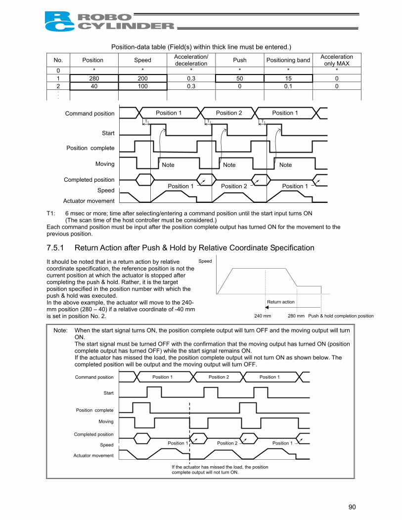
90
Position-data table (Field(s) within thick line must be entered.)
No. Position Speed Acceleration/ deceleration Push Positioning band Acceleration
only MAX 0 * * * * * * 1 280 200 0.3 50 15 0 2 40 100 0.3 0 0.1 0
T1: 6 msec or more; time after selecting/entering a command position until the start input turns ON (The scan time of the host controller must be considered.) Each command position must be input after the position complete output has turned ON for the movement to the previous position. 7.5.1 Return Action after Push & Hold by Relative Coordinate Specification It should be noted that in a return action by relative coordinate specification, the reference position is not the current position at which the actuator is stopped after completing the push & hold. Rather, it is the target position specified in the position number with which the push & hold was executed. In the above example, the actuator will move to the 240-mm position (280 – 40) if a relative coordinate of -40 mm is set in position No. 2.
Note: When the start signal turns ON, the position complete output will turn OFF and the moving output will turn ON.
The start signal must be turned OFF with the confirmation that the moving output has turned ON (position complete output has turned OFF) while the start signal remains ON.
If the actuator has missed the load, the position complete output will not turn ON as shown below. The completed position will be output and the moving output will turn OFF.
Command position
Start
Position complete
Moving
Completed position
Speed
Actuator movement
Position 1 Position 2 Position 1
Note Note Note
Position 1 Position 2 Position 1
T1 T1 T1
Command position
Start
Position complete
Moving
Completed position
Speed
Actuator movement
Position 1 Position 2 Position 1
Position 1 Position 2 Position 1
If the actuator has missed the load, the position complete output will not turn ON.
240 mm 280 mm Push & hold completion position
Speed
Return action

91
7.6 Speed Change during Movement Example of use in operation) The actuator speed is reduced at a certain point during movement. The position 150 mm from the home is set as position 1, and the position 200
mm from the home is set as position 2. The actuator is initially located between the home and position 1. The actuator is moved to position 2 being the target position, at a travel speed of 200 mm/sec to position 1 and that of 100 mm/sec from position 1 to position 2.
Method) In this example, the actuator is caused to move to position 1 and to position 2 successively. Before the actuator is stopped at position 1, command position 2 must be selected/entered and the start signal must be input. To do this, set a wide positioning band at position 1 and cause the start signal for movement to position 2 to be input immediately after the completion signal for movement to position 1 is output. (Command position 2 should be entered while the actuator is moving to position 1.)
RCP2 controller
P L C
[11] [9] [5] [2]
[1]
[6]
[8]
[13] [12] [10] [7] [3]
[14] [4]
PIO
Signal name Start Command position 1 Command position 2 Command position 4 Command position 8 *Pause Reset Servo ON Completed position 1 Completed position 2 Completed position 4 Completed position 8 Position complete Home return completion Zone *Alarm Ready Moving
Category
Input Output
Reference flow Select/enter command position 1.[1]
[2] [3] [4] [5] [6]
[7] [8] [9] [10] [11] [12] [13] [14]
Start input ON
Movement to position 1 starts at 200 mm/sec.
Completed position OFF
Position complete output OFF
Moving output ON
Start input OFF
Select/enter command position 2.
Start input ON
Completed position OFF
Position complete output OFF
Start input OFF
Completed position 1 is output.
Moving output OFF
Movement to position 2 completes.
Position complete output turns ON 10 mm before position 1.
Movement to position 2 starts at 100 mm/sec.
Position complete output turns ON 0.1 mm before position 2.
Completed position 2 is output.
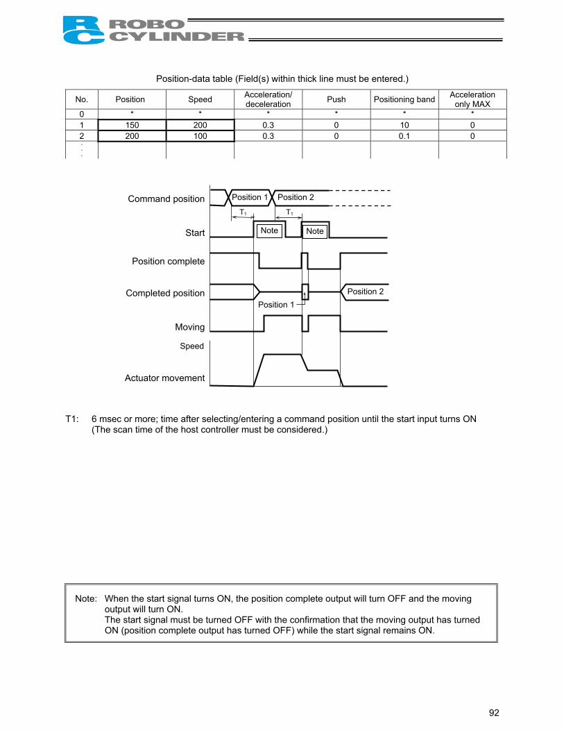
92
Position-data table (Field(s) within thick line must be entered.)
No. Position Speed Acceleration/ deceleration Push Positioning band Acceleration
only MAX 0 * * * * * * 1 150 200 0.3 0 10 0 2 200 100 0.3 0 0.1 0
T1: 6 msec or more; time after selecting/entering a command position until the start input turns ON (The scan time of the host controller must be considered.)
Note: When the start signal turns ON, the position complete output will turn OFF and the moving output will turn ON.
The start signal must be turned OFF with the confirmation that the moving output has turned ON (position complete output has turned OFF) while the start signal remains ON.
Speed
Position 1 Position 2
Position 1
T1 T1
Position 2
Note Note
Command position
Start
Position complete
Completed position
Moving
Actuator movement

93
7.7 Operation at Different Acceleration and Deceleration Settings Example of use in operation) Positioning is performed to the position 150 mm from the home (position 1)
at a speed of 200 mm/sec. The actuator will accelerate at the maximum acceleration and decelerate at 0.1 G.
Method) Entering “1” under “Acceleration only MAX” in the position data will automatically adjust the acceleration to the maximum acceleration.
Entering “0.1” under “Acceleration/deceleration” in the position data will set the deceleration to 0.1 G.
RCP2 controller
P L C
[5] [2] [1] [7] [6] [3] [8] [4]
PIO
Signal name Start Command position 1 Command position 2 Command position 4 Command position 8 *Pause Reset Servo ON Completed position 1 Completed position 2 Completed position 4 Completed position 8 Position complete Home return completion Zone *Alarm Ready Moving
Category
Input Output
Reference flow Select/enter command position 1.[1]
[2]
[3] [4]
[5] [6]
[7] [8]
Start input ON
Completed position OFF
Position complete output OFF
Moving output ON
Start input OFF
Moving output OFF
Movement to position 1 completes.
Position complete output turns ON 0.1 mm before position 1.
Completed position 1 is output.
Movement to position 1 starts at the maximum acceleration.
Moves at constant speed (200 mm/sec).
Decelerates at 0.1 G.
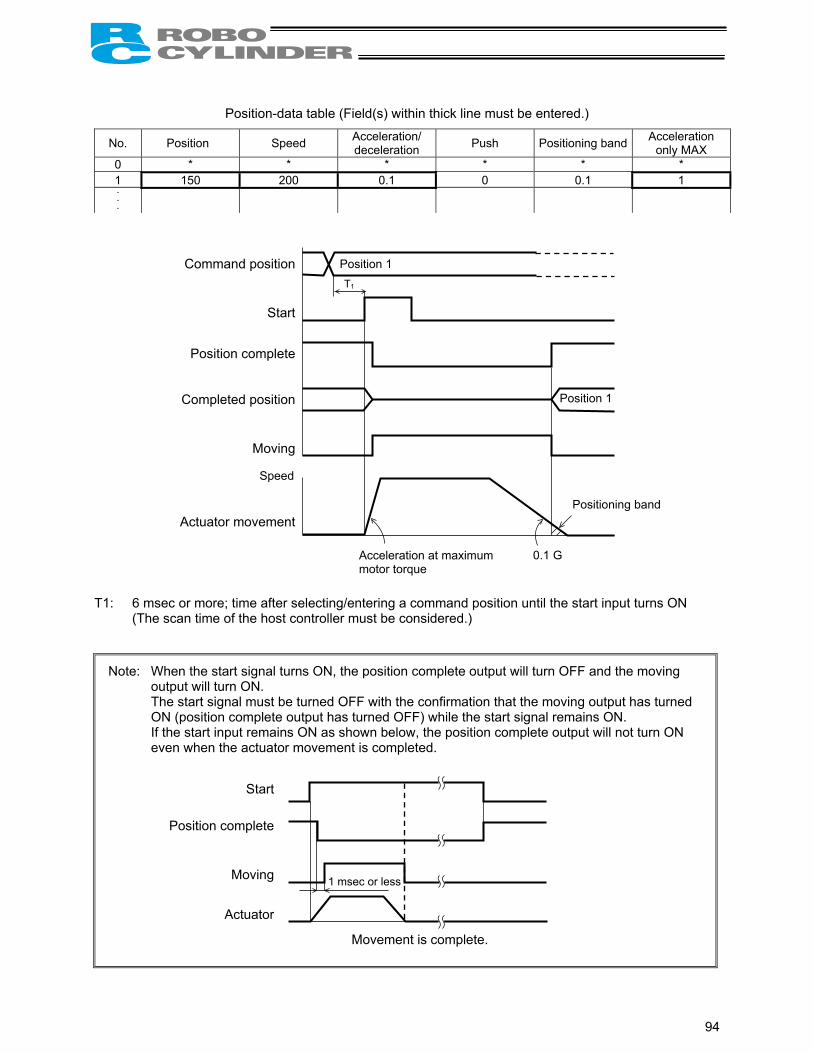
94
Position-data table (Field(s) within thick line must be entered.)
No. Position Speed Acceleration/ deceleration Push Positioning band Acceleration
only MAX 0 * * * * * * 1 150 200 0.1 0 0.1 1
T1: 6 msec or more; time after selecting/entering a command position until the start input turns ON (The scan time of the host controller must be considered.)
Note: When the start signal turns ON, the position complete output will turn OFF and the moving output will turn ON.
The start signal must be turned OFF with the confirmation that the moving output has turned ON (position complete output has turned OFF) while the start signal remains ON.
If the start input remains ON as shown below, the position complete output will not turn ON even when the actuator movement is completed.
Speed
Position 1
Position 1
T1
Command position
Start
Position complete
Completed position
Moving
Actuator movement
0.1 G
Positioning band
Acceleration at maximum motor torque
Start
Position complete
Moving
Actuator
1 msec or less
Movement is complete.

95
7.8 Pause Example of use in operation) The actuator is paused during movement.
Method) Use the pause input.
RCP2 controller
P L C
[5] [2] [1]
[8] [6] [11] [10] [3]
PIO
Signal name Start Command position 1 Command position 2 Command position 4 Command position 8 *Pause Reset Servo ON Completed position 1 Completed position 2 Completed position 4 Completed position 8 Position complete Home return completion Zone *Alarm Ready Moving
Category
Input Output
Reference flow
Select/enter a desired command position.[1] [2] [3]
[4] [5] [6] [7] [8]
[9]
[10]
[11] [12]
Start input ON
Completed position OFF
Position complete output OFF
Moving output ON
Start input OFF
Moving output OFF
Movement to the selected position completes.
Position complete output ON
Completed position is output.
Movement to the selected position starts.
Pause input OFF (Actuator decelerates to a stop.)
Pause input ON (Movement starts.)
[12][9] [7] [4]
Moving output OFF
Moving output ON

96
T1: 6 msec or more; time after selecting/entering a command position until the start input turns ON (The scan time of the host controller must be considered.)
Note: When the start signal turns ON, the position complete output will turn OFF and the moving output will turn ON.
The start signal must be turned OFF with the confirmation that the moving output has turned ON (position complete output has turned OFF) while the start signal remains ON.
The remaining movement can be cancelled by turning ON the reset input during pause. (The controller will detect a rise of the reset signal and cancel the remaining movement.) If parameter No. 25 (I/O pattern) is set to “0: [Conventional],” the reset input is not available.
Command position
Start
Position complete
Completed position
Pause
Moving
Actuator movement
Speed
4 msec or less
Note
Deceleration to a stop Start of remaining movement
Command position
Start
Position complete
Completed position
Pause
Reset
Moving
Actuator movement
Speed
4 msec or more

97
7.9 Zone Signal Output Example of use in operation) While the actuator is moving a zone signal is output inside the zone
enclosed by distances of 40 mm and 120 mm from the home. (40 mm ≤ Zone signal output ≤ 120 mm)
Method) Use the parameters “Zone boundary+” and “Zone boundary–” to set the zone in which the zone signal is output, as shown below:
Parameter No. 1 Zone boundary+ 120 Parameter No. 2 Zone boundary– 40
If parameter No. 25 is set to “3: [2 zone output signals],” two zone output signals are available. Set the second zone value using parameter No. 23 (Zone 2+) and No. 24 (Zone 2–). Note) The zone function is not available if parameter No. 25 (PIO pattern) is set to “2: [64-point
positioning]” or “4: [Teaching].”
RCP2 controller
P L C
[5] [2]
[1] [9] [8] [3] [7] [6] [10] [4]
PIO
Signal name Start Command position 1 Command position 2 Command position 4 Command position 8 *Pause Reset Servo ON Completed position 1 Completed position 2 Completed position 4 Completed position 8 Position complete Home return completion Zone *Alarm Ready Moving
Category
Input Output
Reference flow
Select/enter a desired command position.[1]
[2] [3] [4] [5] [6] [7] [8] [9] [10]
Start input ON
Completed position OFF
Position complete output OFF
Moving output ON
Start input OFF
Moving output OFF
Movement to the selected position completes.
Position complete output ON
Completed position is output.
Movement to the selected position starts.
Actuator enters the zone. Zone output ON
Actuator exits the zone. Zone output OFF

98
T1: 6 msec or more; time after selecting/entering a command position until the start input turns ON (The scan time of the host controller must be considered.)
Note: When the start signal turns ON, the position complete output will turn OFF and the moving output will turn ON.
The start signal must be turned OFF with the confirmation that the moving output has turned ON (position complete output has turned OFF) while the start signal remains ON.
Example of other zone output)
Zone output at 120 or more Zone output at 40 or less
Zone boundary+ Maximum stroke length Zone boundary+ 40
Zone boundary– 120 Zone boundary– 0
Command position
Start
Position complete
Completed position
Zone
Moving
Actuator movement
Speed
T1 Note
40 mm 120 mm
Zone Zone
120 40

99
7.10 Incremental Moves Example of use in operation) The actuator is caused to move from the home to the 30-mm position, from
which it will be moved repeatedly in increments of 10 mm. The travel speed from the home to the 30-mm position is set as 100 mm/sec, and that for 10-mm incremental moves is set as 20 mm/sec.
RCP2 controller
P L C
[13] [10] [5] [2]
[1]
[9]
[7]
[15] [14] [11] [6] [3] [16] [11] [8] [4]
PIO
Signal name Start Command position 1 Command position 2 Command position 4 Command position 8 *Pause Reset Servo ON Completed position 1 Completed position 2 Completed position 4 Completed position 8 Position complete Home return completion Zone *Alarm Ready Moving
Category
Input Output
Reference flow
Select/enter command position 1.[1] [2]
[3]
[4]
[5] [6]
[7] [8] [9]
[10]
[11]
[12]
[13]
[14] [15] [16]
Start input ON
Movement to position 1 starts.
Completed position OFF
Position complete output OFF
Moving output ON
Start input OFF
Position complete output ON
Completed position 1 is output.
Moving output OFF
Select/enter command position 2.
Start input ON
Completed position OFF
Position complete output OFF
Moving output ON
Start input OFF
Completed position 2 is output.
Moving output OFF
Movement to the +10 mm position completes.
Position complete output ON
Movement to position 1 completes.
Movement to +10 mm from the current position starts.

100
Position-data table (Field(s) within thick line must be entered.)
No. Position Speed Acceleration/ deceleration Push Positioning band Acceleration
only MAX 0 * * * * * * 1 30 100 0.3 0 0.1 0 2 10 20 0.3 0 0.1 0
T1: 6 msec or more; time after selecting/entering a command position until the start input turns ON (The scan time of the host controller must be considered.)
Note 1: When the start signal turns ON, the position complete output will turn OFF and the moving output will turn ON.
The start signal must be turned OFF with the confirmation that the moving output has turned ON (position complete output has turned OFF) while the start signal remains ON.
If the start input remains ON as shown below, the position complete output will not turn ON even when the actuator movement is completed.
Note 2: When a soft limit is reached as a result of repeated incremental moves, the actuator will stop
at that position and the position complete signal will be output.
=
Command position
Start
Position complete
Completed position
Moving
Actuator movement
Speed
Position 1 Position 2 T1 T1
Note 1
Note 2
Position 1 Position 2 Position 2
30 40 50 60 70 Time
Distance from home
Start
Position complete
Moving
Actuator
1 msec or less
Movement is complete.

101
7.11 Notes on Incremental Mode (1) Notes on positioning operation
Selecting/entering a position number using relative coordinates during positioning will cause the actuator to move to the position corresponding to the initial position plus the increment. (If the increment is a negative value, the actuator will move to the position corresponding to the initial position minus the increment.) Example) If the start signal for movement to position 2 is input while the actuator is moving to
position 1, the actuator will move to the position 40 mm from the home.
No. Position Speed 0 * * 1 30 100 2 10 100
If the start signal for movement to an incremental position number is input multiple times during positioning, the actuator will move to the position corresponding to the initial position plus the “increment x number of times the signal was input.” Example) If the start signal for movement to position 2 is input twice while the actuator is moving to
position 1, the actuator will move to the position 50 mm from the home. (2) Note on push & hold operation
If the start signal is input with an incremental position number selected/entered while the actuator is moving in the push & hold mode, the actuator will move to the position corresponding to the position at the time of start input plus the increment. Therefore, the end position will become indeterminate.
Distance Position from home: 40
Command position
Start
Position complete
Completed position
Moving
Actuator movement
Speed
Position 1 Position 2
=
Position from home: 50 Distance
Command position
Start
Position complete
Completed position
Moving
Actuator movement
Position 1 Position 2
Speed
Position 2
Position 2
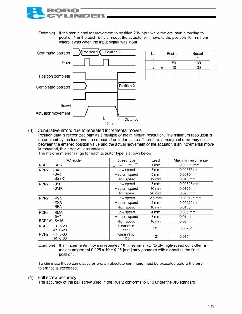
102
Example) If the start signal for movement to position 2 is input while the actuator is moving to position 1 in the push & hold mode, the actuator will move to the position 10 mm from where it was when the input signal was input.
No. Position Speed 0 * * 1 50 100 2 10 100
(3) Cumulative errors due to repeated incremental moves Position data is recognized only as a multiple of the minimum resolution. The minimum resolution is determined by the lead and the number of encoder pulses. Therefore, a margin of error may occur between the entered position value and the actual movement of the actuator. If an incremental move is repeated, this error will accumulate. The maximum error range for each actuator type is shown below:
RC model Speed type Lead Maximum error range RCP2 -RPA 1 mm 0.00125 mm
Low speed 3 mm 0.00375 mm Medium speed 6 mm 0.0075 mm
RCP2 -SA5 -SA6 -SS (R) High speed 12 mm 0.015 mm
Low speed 5 mm 0.00625 mm Medium speed 10 mm 0.0125 mm
RCP2 -SM -SMR High speed 20 mm 0.025 mm
Low speed 2.5 mm 0.003125 mm Medium speed 5 mm 0.00625 mm
RCP2 -RSA -RXA -RFA High speed 10 mm 0.0125 mm
Low speed 4 mm 0.005 mm Medium speed 8 mm 0.01 mm
RCP2 -RMA -SA7 RCP2W -SA16 High speed 16 mm 0.02 mm RCP2 -RTB-20 -RTC-20
Gear ratio 1/20 18° 0.0225°
RCP2 -RTB-30 -RTC-30
Gear ratio 1/30 12° 0.015°
Example) If an incremental move is repeated 10 times on a RCP2-SM high-speed controller, a maximum error of 0.025 x 10 = 0.25 [mm] may generate with respect to the final position.
To eliminate these cumulative errors, an absolute command must be executed before the error tolerance is exceeded.
(4) Ball screw accuracy
The accuracy of the ball screw used in the RCP2 conforms to C10 under the JIS standard.
=
Distance 10 mm
Command position
Start
Position complete
Completed position
Actuator movement
Speed
Position 1 Position 2
Position 2

103
7.12 Jogging/Teaching Using PIO First, cause the position complete signal to turn ON by referring to 7.1, “How to Start.” If parameter No. 25 (PIO pattern) is set to “4: [Teaching],” the actuator can be jogged using PIO. The current actuator position can also be read into the controller’s position table using PIO. When reading the current position into the position table, all data other than position (speed, acceleration, etc.), if not already defined, will be automatically set to the default values in the applicable parameters. Note) If a teaching pendant is connected (PORT is ON), the current position cannot be read into the
position table. Example of use in operation) The actuator is caused to move using the +jog input or –jog input and the
current position is read into position No. 1.
RCP2 controller
P L C
[4]
[2]
[4] [1]
[7] [5] [1]
[4] [1]
[3]
[6]
PIO
Signal name Command position 1 Command position 2 Command position 4 Command position 8 Operation mode +Jog *Pause Current-position write Start Servo ON –Jog Reset Completed position 1 Completed position 2 Completed position 4 Completed position 8 Current operation mode Write completion Position complete Home return completion *Alarm Ready Moving
Category
Input Output
*Pause input OFF Reset input OFF Start input OFF Operation mode input ON Current operation mode output ON Move the actuator using +jog input or –jog input. Select/enter command position 1. Current-position write input ON Write completion output ON Current-position write input OFF
Reference flow
[1]
[2] [3] [4] [5]
[6] [7]

104
Jogging/teaching timing T1: 20 msec or more; time after the current-position write input is turned ON until writing of the current
position is started When the operation mode (MODE) input is turned ON, the current operation mode (MODES) output will turn ON to activate the teaching mode where jogging and teaching can be performed using PIO. The controller will not switch to the teaching mode unless the operation mode (MODE) input is turned ON while the pause input, reset input and start input are OFF. To check if the controller is in the teaching mode, check if the current operation mode (MODES) output is ON. The actuator will stop if both the +jog input and –jog input are turned ON. Turn OFF both inputs, and then resume jogging in one direction. If the current-position write (PWRT) input has remained ON for 20 msec or longer, the current actuator position will be written to the selected command position number. When the writing is complete, the write completion (WEND) output will turn ON. To check if the writing has completed, check if the write completion (WEND) output is ON. Turning OFF the current-position write (PWRT) input will cause the write completion (WEND) output to turn OFF.
Note: Be sure to enable the pause signal using parameter No. 15 (by setting the parameter to “0”) (the pause signal is enabled at the factory). The system cannot switch to the teaching mode if the pause signal is disabled (i.e., the above parameter is set to “1”).
If a signal to be written is input from the PLC while the position table screen is open on the PC or teaching pendant, the position data display will not be refreshed. Perform one of the following operations to check the retrieved position data: PC --- Click the button. Teaching pendant --- Turn on the PORT switch.
Operation mode
Current operation mode
+Jog(*Pause)
-Jog(Reset)
Command position
Current-position write(Start)
Write completion(Position complete)
Position 1
T1
(MODE) (MODES) (PWRT) (WEND)

105
7.13 Operation in the “4 Points (Air Cylinder)” Mode First, refer to 7.1, “How to Start,” to turn ON the position complete signal. Example of operation) Turn on the power, and then cause the actuator to move back and forth between
the rear end (5 mm) and front end (390 mm) via intermediate point 1 (200 mm) (based on the standard specification).
RCP2 controller
P L C
[1] [5] [14]
[10] [13]
[6] [9]
[4] [7]
[12] [15]
[8] [11]
[2]
[3]
Signal name
Rear end move
Front end move
Intermediate point 1 move
Intermediate point 2 move
*Pause
Reset
Rear end complete
Front end complete
Intermediate point 1 complete
Intermediate point 2 complete
Zone
Position complete
Home return completion
*Alarm
Category
Input Output
[1] [2]
[3] [4] [5] [6] [7] [8] [9] [10] [11] [12] [13] [14] [15]
Reference flow The rear end move input turns ON
Home return starts
The position complete output turns OFF
Home return completes
The home return completion output turns ON
The actuator starts moving to the rear end
The actuator arrives at the rear end, upon which the rear end complete output turns ON.
The rear end move input turns OFF The intermediate point 1 move input turns ON
The actuator starts moving to intermediate point 1 The rear end complete output turns OFF
The actuator arrives at intermediate point 1, upon which the intermediate point 1 complete output turns ON
The intermediate point 1 move input turns OFF The front end move input turns ON
The actuator starts moving to the front end The intermediate point 1 complete output turns OFF
The actuator arrives at the front end, upon which the front end complete output turns ON
The front end move input turns OFF The rear end move input turns ON
The actuator starts moving to the rear end The front end complete output turns OFF
PIO

106
Note: Movement commands are executed based on the rise edge, so input each signal continuously for 6 msec or more.
If two or more movement commands are input simultaneously, they will be executed according to the following priorities:
Priorities: [1] Rear end, [2] Front end, [3] Intermediate point 1, [4] Intermediate point 2 The sequence circuit on the PLC side must ensure only one command is input at a time.
Mec
hani
cal e
nd
Hom
e po
sitio
n
Rea
r end
Inte
rmed
iate
poi
nt 1
Fron
t end
Rear end move
Intermediate point 1 move
Front end move
Position complete
Home return completion
Rear end complete
Intermediate point 1 complete
Front end complete
Speed
Actuator movement
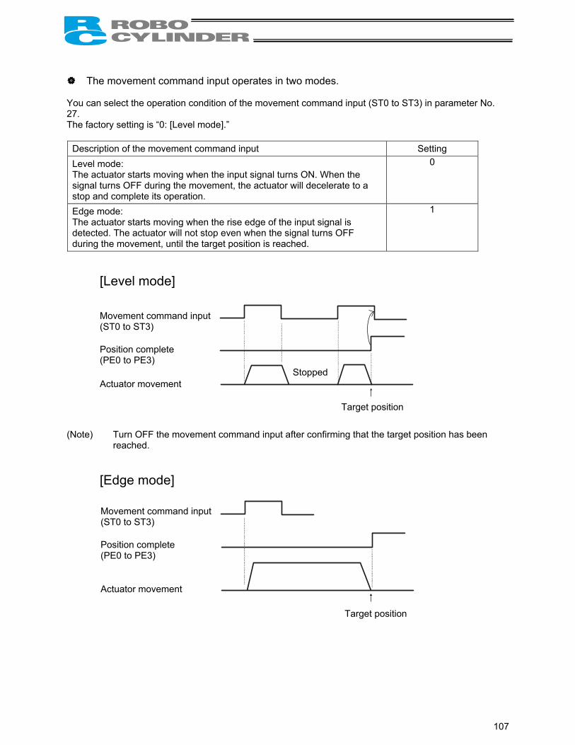
107
The movement command input operates in two modes. You can select the operation condition of the movement command input (ST0 to ST3) in parameter No. 27. The factory setting is “0: [Level mode].”
Description of the movement command input Setting Level mode: The actuator starts moving when the input signal turns ON. When the signal turns OFF during the movement, the actuator will decelerate to a stop and complete its operation.
0
Edge mode: The actuator starts moving when the rise edge of the input signal is detected. The actuator will not stop even when the signal turns OFF during the movement, until the target position is reached.
1
[Level mode] (Note) Turn OFF the movement command input after confirming that the target position has been
reached.
[Edge mode]
Movement command input (ST0 to ST3) Position complete (PE0 to PE3) Actuator movement
Stopped
Target position
Movement command input (ST0 to ST3) Position complete (PE0 to PE3)
Actuator movement
Target position

108
Handling of the pause (*STP) signal This signal is a contact B signal, meaning that it must remain ON while the actuator is moving. If the pause signal turns OFF while the actuator is moving, the actuator will decelerate to a stop. The actuator will start moving when the signal turns ON again. Use this signal as an interlock that actuates when an operator entry prohibition sensor or contact prevention sensor is activated.
If the pause signal is not to be used, set parameter No. 15 (Pause input disable selection) to “1,” and the actuator will move even when this signal is OFF.
(Note) When the “edge mode” is selected as the movement command type, you can change the target position while the actuator is stopped with this signal turned OFF, as follows:
[1] Input a reset signal (RES) for 6 msec or more to cancel the remaining travel. Next, turn ON the pause signal, and then input a movement command specifying the new target
position. (Example) If the pause signal is turned OFF while the actuator is moving following the input of an
intermediate point 1 move command, the accelerator will decelerate to a stop. → Turn OFF the intermediate point 1 move signal, and then turn ON the reset signal for
6 msec or more. → Turn ON the pause signal again, and then input the front end move signal.
[2] After inputting a movement command specifying the new target position, turn ON the pause input. (Example) If the pause signal is turned OFF while the actuator is moving following the input of an
intermediate point 1 move command, the accelerator will decelerate to a stop. → Turn OFF the intermediate point 1 move signal, and turn ON the front end move
signal. → When the pause signal is turned ON again, the controller will recognize the front end
as the new target position.
Intermediate point 1 move
Front end move
Reset
Pause
Front end complete
Actuator movement
(ON for 6 msec or more)
Stopped
The front end becomes the target position.
Intermediate point 1 move
Front end move
Pause
Front end complete
Actuator movement Stopped
The front end becomes the target position.

109
8. Parameters 8.1 Parameter Classification Parameters are classified into four types according to their content. Category:
a: Parameter relating to the actuator stroke range b: Parameter relating to the actuator operating characteristics c: Parameter relating to the external interface d: Servo gain adjustment
8.2 Parameter Table
No. Category Name Unit Default factory setting
1 a Zone boundary 1+ mm Effective actuator length
2 a Zone boundary 1– mm Effective actuator length
3 a Soft limit+ mm Effective actuator length
4 a Soft limit– mm Effective actuator length
5 a Home return direction (0: [Reverse]/1: [Forward]) - (In accordance with the specification at the time
of order) 6 b Push & hold stop judgment period msec 255
7 d Servo gain number - Set individually in accordance with the actuator characteristics.
8 b Default speed mm/sec Set individually in accordance with the actuator characteristics.
9 b Default acceleration/deceleration G Set individually in accordance with the actuator characteristics.
10 b Default positioning band (in-position) mm 0.10
11 b Default acceleration only MAX flag - 0
12 b Current-limiting value at standstill during positioning % Set individually in accordance with the actuator
characteristics.
13 b Current-limiting value during home return % Set individually in accordance with the actuator characteristics.
14 (Reserved for future expansion)
15 c Pause input disable selection (0: [Enable]/1: [Disable]) - 0
16 c Serial communication speed bps 38400
17 c Minimum delay time for slave transmitter activation msec 5
18 (Reserved for future expansion)
19 (Reserved for future expansion)
20 (Reserved for future expansion)
21 c Servo ON input disable selection (0: [Enable]/1: [Disable]) - 1
22 a Home return offset mm Set individually in accordance with the actuator characteristics.
23 a Zone boundary 2+ mm Effective actuator length
24 a Zone boundary 2– mm Effective actuator length
25 c PIO pattern selection - 0: [Conventional]
26 b PIO jog speed mm/sec 100
27 c Movement command type (0: [Level]/1: [Edge]) - 0: [Level]
28 b Direction of excitation phase signal detection (0: [Reverse]/1: [Forward]) - Set individually in accordance with the actuator
characteristics.
(Note) The numbers are displayed on the PC software screen but not on the teaching pendant. The category codes are provided only for convenience and not displayed on either the PC software screen or teaching pendant.

110
8.3 Parameter Settings
If a parameter has been changed, always restart the controller using a software reset command or by reconnecting the power.
8.3.1 Parameters Relating to the Actuator Stroke Range
Soft limit Set the soft limit in the positive direction in parameter No. 3, and that in the negative direction in parameter No. 4. The factory setting for the soft limits conforms to the effective actuator length. Change the settings, as necessary, to prevent crash with an obstacle or when the actuator must be stroked slightly beyond its effective length. A wrong soft limit setting will cause the actuator to crash into the mechanical end, so exercise due caution. The minimum setting unit is “0.01 [mm].” (Note) To change a soft limit, set a value corresponding to 0.3 mm outside of the effective range.
Example) Set the effective range to between 0 mm and 80 mm Parameter No. 3 (positive side) 80.3 Parameter No. 4 (negative side) –0.3
Zone boundary Set the zone in which a zone output signal (ZONE1 or ZONE2) will turn ON. (Note) ZONE2 is enabled only when “2 zone output signals” is selected as the PIO pattern. The zone signal turns ON only when the current coordinate position is inside the negative (-) boundary and positive (+) boundary settings. The positive and negative boundaries for the ZONE1 signal are set in parameter No. 1 and No. 2, respectively. The positive and negative boundaries for the ZONE2 signal are set in parameter No. 23 and No. 24, respectively. The minimum setting unit is “0.01 [mm].”
Example) Use ZONE1 as an intermediate limit switch inside 100 and 200 mm, and use ZONE2 as a simple ruler inside 270 and 275 mm, with an actuator having a 300-mm stroke Parameter No. 1 (positive side) 200, parameter No. 2 (negative side) 100 Parameter No. 23 (positive side) 275, parameter No. 24 (negative side) 270
0 (Home)
ZONE1 turns ON ZONE2 turns ON
100 200 270 275 300 mm
Soft limits set in the controllerApprox. 0.3 mm
Effective range
Allowable jogging/inching range after home return
8 0 Approx. 0.1 mm Approx. 0.1 mm
0
Approx. 0.3 mm

111
Home return direction Unless specified by the user, the home return direction is set to the motor direction at the factory. Should a need arise to change the home direction after the actuator has been assembled into your system, reverse the setting in parameter No. 5 between “0” and “1.” Also change the parameters for home return offset, soft limits and direction of excitation phase signal detection, if necessary.
Note: The home direction cannot be reversed for a rod-type actuator. If the home direction is reversed, all position data that have been input will be cleared.
Home return offset The controller is shipped from the factory with an optimal value set in parameter No. 22, so the distance from each mechanical end to the home becomes uniform. The minimum setting unit is “0.01 [mm].” The home return offset can be adjusted in the following conditions: [1] Want to align the actuator home and the system’s mechanical home after the actuator has been
assembled into the system [2] Want to set a new home after reversing the factory-set home direction [3] Want to eliminate a slight deviation generated after replacing the actuator
Note: If the home return offset has been changed, the soft limit parameters must also be adjusted accordingly.
8.3.2 Parameters Relating to the Actuator Operating Characteristics
PIO jog speed Define the speed at which the actuator will be jogged using PIO in the teaching mode. The factory setting is “100 [mm/sec].” Set an optimal value for the specific application in parameter No. 26.
Default speed The factory setting is the rated speed of the actuator. When a target position is written to an unregistered position table or the current position is read in the teaching mode, the setting in this parameter will be used as the speed data for the applicable position number. To reduce the default speed from the rated speed, change the setting in parameter No. 8.
Default acceleration/deceleration The factory setting is the rated acceleration/deceleration of the actuator. When a target position is written to an unregistered position table or the current position is read in the teaching mode, the setting in this parameter will be used as the acceleration/deceleration data for the applicable position number. To reduce the default acceleration/deceleration from the rated acceleration/deceleration, change the setting in parameter No. 9.

112
Default positioning band (in-position) The factory setting is “0.10 [mm].” When a target position is written to an unregistered position table or the current position is read in the teaching mode, the setting in this parameter will be used as the positioning band data for the applicable position number. Increasing the default positioning band will allow the position complete signal to be output early. Change the setting in parameter No. 10, as necessary.
Default acceleration only MAX flag To cause the actuator to decelerate gradually when stopping, a lower acceleration/deceleration should be set. However, this will also reduce the acceleration. This parameter allows for quick acceleration while reducing the deceleration. This setting is permitted only when the actual payload is no more than one-third the rated load capacity. Check the rated load capacity by referring to Appendix, “List of Supported Actuator Specifications.” The factory setting is “0: [Disable].” When a target position is written to an unregistered position table or the current position is read in the teaching mode, the setting in this parameter will be used as the acceleration only MAX data for the applicable position number. To enable the default value, change parameter No. 11 to “1: [Enable].”
Push & hold stop judgment period This parameter is used as a judgment condition when determining if the load was contacted and the push & hold operation has completed. The push & hold operation is judged complete if the current-limiting value set in the position table has been maintained for the period set in parameter No. 6. Set an optimal value by considering the shape and strength of the load, as well as the current-limiting value. The minimum setting unit is “1 [msec],” and the maximum judgment period is “255 [msec].” The factory setting is “255 [msec].” (Note) If the load has shifted and the current has changed during the push & hold judgment, the
judgment follows the timing chart shown below. This example assumes a judgment period of 255 msec.
After reaching the push current, it is maintained for 200 msec. The current drops during the subsequent 20-msec period, and accordingly the count is decremented by 20. Therefore, when the operation is resumed the count will start from 180. Since the count will reach 255 after 75 msec at the push current, the controller will determine that the push & hold operation has completed. In this example, the total judgment period is 295 msec.
Push current
20 msecStart position Target position Counting starts
Counting continues until 200
Count is decremented to 180
Count is incremented to 255
Judgment of push & hold completion
75 msec

113
Current-limiting value at standstill during positioning The factory setting conforms to the standard specification of the actuator. Increasing this setting will increase the holding torque at standstill. This setting need not be changed in normal conditions of use. However, to prevent hunting caused by large external force applied while the actuator is at standstill, the value set in parameter No. 12 must be increased. (Do not increase the value beyond 70%.)
Current-limiting value during home return The factory setting conforms to the standard specification of the actuator. Increasing this setting will increase the home return torque. This setting need not be changed in normal conditions of use. However, if an increased slide resistance causes the home return to complete before the correct position depending on the affixing method, load condition or other factor when the actuator is used in a vertical application, the value set in parameter No. 13 must be increased. (Do not increase the value beyond 75%.)
Direction of excitation phase signal detection After the power has been turned on, excitation phase detection is performed when the servo is turned on for the first time. This parameter defines the direction in which this detection is performed. This setting need not be changed in normal conditions of use. However, if the actuator is contacting the mechanical end or any other obstacle and cannot be moved by hands when the power is on, you should change the setting to a direction that allows the motor to operate easily. Set the value of parameter No. 28 to “0” or “1.” If the detection direction should be the same as the home return direction, set in this parameter the same value currently set in parameter No. 5, “Home return direction.” To set the direction opposite to the home return direction, set the value different from the one currently set in parameter No. 5, “Home return direction.” (Example 1) The power is turned on when the vertically positioned slider is contacting the bottom
mechanical end, with the motor installed on top. (Example 2) The power is turned on when the vertically positioned slider is contacting the bottom
mechanical end, with the motor installed at bottom. * This parameter is supported by PC software version 5.0.1.0 or later, as well as teaching pendant RCA-T
version 1.67 or later, RCA-E/P version 1.67 or later and RCB-J version 1.04 or later.
Set the same value.
Set different values.
Top
Bottom
Top
Bottom
Home position
The slider is contacting the bottom mechanical end.
Home return direction
Direction of excitation phase signal detection
Home position
The slider is contacting the bottom mechanical end.
Home return direction
Direction of excitation phase signal detection

114
8.3.3 Parameters Relating to the External Interface
PIO pattern selection Select the PIO operation pattern in parameter No. 25. This setting forms the basis of operation, so be sure to set this parameter at the beginning. The factory setting is “0: [Conventional].”
Parameter No. 25 setting Feature of PIO pattern
0 Conventional This pattern is compatible with the pin assignments of the RCP controller.
1 Standard All functions of the RCP controller are available, plus the home-return command input, servo ON input, reset input, moving output and ready output.
2 64-point positioning Compared with the standard pattern offering only 16 positioning points, this pattern provides up to 64 positioning points. However, the servo ON input, ready output and zone output have been removed.
3 2 zone output signals Compared with the standard pattern offering only one zone output signal, this pattern provides two zone output signals. However, the moving output has been removed. The boundaries for the second zone output signal are specified in parameter Nos. 23 and 24.
4 Teaching This pattern allows for normal positioning operation, as well as jogging and writing of current position to a specified position using I/Os. Switching between the normal positioning mode and teaching mode is effected by the MODE input signal. The mode switching completion output has been added to indicate that the modes have been switched. However, the zone output has been removed. (Note) Position data can be rewritten up to around 100,000 times.
5 4 points (air cylinder) Use of the RCP2 as an air cylinder is assumed in this pattern. The number of positioning points is limited to four, but a direct command input and a position complete output are provided for each target position in line with the conventional practice of air cylinder control. This lets the user control the RCP2 just like an air cylinder.

115
Movement command type When the PIO pattern is set to “4 points,” define the operation condition of the movement command input (ST0 to ST3) in parameter No. 27. The factory setting is “0: [Level mode].”
Description of the movement command input Setting Level mode: The actuator starts moving when the input signal turns ON. When the signal turns OFF during the movement, the actuator will decelerate to a stop and complete its operation.
0
Edge mode: The actuator starts moving when the rise edge of the input signal is detected. The actuator will not stop even when the signal turns OFF during the movement, until the target position is reached.
1
[Level mode] (Note) Turn OFF the movement command input after confirming that the target position has been
reached.
[Edge mode]
Movement command input (ST0 to ST3) Position complete (PE0 to PE3) Actuator movement
Stopped
Target position
Movement command input (ST0 to ST3) Position complete (PE0 to PE3)
Actuator movement
Target position
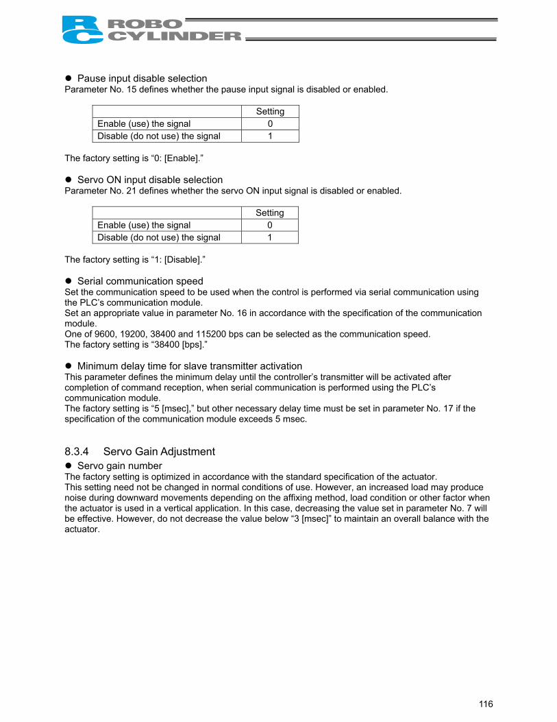
116
Pause input disable selection Parameter No. 15 defines whether the pause input signal is disabled or enabled.
Setting Enable (use) the signal 0 Disable (do not use) the signal 1
The factory setting is “0: [Enable].”
Servo ON input disable selection Parameter No. 21 defines whether the servo ON input signal is disabled or enabled.
Setting Enable (use) the signal 0 Disable (do not use) the signal 1
The factory setting is “1: [Disable].”
Serial communication speed Set the communication speed to be used when the control is performed via serial communication using the PLC’s communication module. Set an appropriate value in parameter No. 16 in accordance with the specification of the communication module. One of 9600, 19200, 38400 and 115200 bps can be selected as the communication speed. The factory setting is “38400 [bps].”
Minimum delay time for slave transmitter activation This parameter defines the minimum delay until the controller’s transmitter will be activated after completion of command reception, when serial communication is performed using the PLC’s communication module. The factory setting is “5 [msec],” but other necessary delay time must be set in parameter No. 17 if the specification of the communication module exceeds 5 msec. 8.3.4 Servo Gain Adjustment
Servo gain number The factory setting is optimized in accordance with the standard specification of the actuator. This setting need not be changed in normal conditions of use. However, an increased load may produce noise during downward movements depending on the affixing method, load condition or other factor when the actuator is used in a vertical application. In this case, decreasing the value set in parameter No. 7 will be effective. However, do not decrease the value below “3 [msec]” to maintain an overall balance with the actuator.

117
9. Controlling Multiple Controllers via Serial Communication
This section explains the connection method to be used when multiple controllers are controlled using the PC or PLC’s communication module as the host. 9.1 Basic Specifications
Specification item Description Maximum number of units that can be connected 16 units Maximum cable length 100 m or less Terminal resistor 220 Ω
Provide a communication path via bus connection and be sure to provide a terminal resistor at the end. 9.2 Connection Example
Note: Do not connect the teaching pendant and PC at the same time. If both are connected at the same time, a communication error (message level) will occur.
PC, etc.
Teaching pendant <RCA-T/TD>
Optional Cable length: 5
PC software <RCB-101-MW>
Optional
RS232C cross cable (Provided by the user)
Components:
SIO converter (with built-in terminal resistor) <RCB-TU-SIO-A> Vertical type <RCB-TU-SIO-B> Horizontal type
FG 0V 24V
Input power supply
Controller power supply
Terminal resistor R = 220 Ω
Controller link cable <CB-RCB-CTL002>
ADRS switch: 0
Controller 1
ADRS switch: 1
Controller 2
ADRS switch: n-1
Controller n
E-Con connector (AMP 4-1473562-4: housing color green) E-Con connector (AMP 3-1473562-4: housing color orange) Junction (AMP 5-1473574-4)
Green Green Green
(Note) External equipment communication cable <CB-RCA-SIO-***> cannot be used for connection to a PC, PLC, etc.
PERSONAL COMPUTER

118
9.3 SIO Converter This is a converter unit conforming to RS485/232C. [1] Power/emergency-stop terminal block (TB2)
EMG1, EMG2 Provide a contact output for the emergency-stop switch on the teaching pendant. EMG1 and EMG2 connect to the emergency-stop switch on the teaching pendant when the PORT switch is ON, or are shorted when the PORT switch is OFF. These terminals comprise an interlock with a safety circuit provided by the user.
24V Positive side of the 24-V power supply (power supply for the teaching pendant and conversion circuit)
0V Negative side of the 24-V power supply FG FG of the 24-V power supply
(Note) 0V connects to pin 7 (GND) in the controller’s communication connector.
Connection method Use a connection cable satisfying the following specifications:
Item Specification Applicable wire size Single wire: φ 0.8 to 1.2 mm / Stranded: AWG size 20 to 18 (end is soldered) Stripped wire length 10 mm
[2] Link-connection terminal block (TB1) [1] Power/emergency-stop terminal block (TB2)
[6] Monitor LEDs
[3] D-sub, 9-pin connector
[4] Mini DIN, 8-pin connector [5] PORT switch
TB1
A B
LED1 LED2
RS232PORT
ON
TB2
EM
G2
EM
G1
24V 0V FG
Used for continuity check Insert a flathead screwdriver with a bit size of approx. 2.6 mm.
Connection cable

119
[2] Link-connection terminal block (TB1)
A connection port for linking the controller. “A” on the left side connects to pin 1 (SGA) in the controller’s communication connector. “B” on the right side connects to pin 2 (SGB) in the controller’s communication connector. (Note) Be sure to use twisted pair wires for the above two connections (SGA/SGB).
[3] D-sub, 9-pin connector
A connection port with the host PC or PLC’s communication module. [4] Mini DIN, 8-pin connector
A connection port with the teaching pendant. [5] PORT switch
A switch for enabling/disabling the teaching pendant. Set the switch to ON when a teaching pendant is used, or OFF when teaching pendant is not used.
[6] Monitor LEDs
LED1 --- Lit when the controller is transmitting LED2 --- Lit when the RS232 is transmitting

120
9.4 Address Switch Set an address (0 to 15) as a hexadecimal (0 to F) using the ADRS switch on the front panel of each controller to define the slave number for the controller. Assign “0” to the controller nearest the host, and then assign 1, 2, 3, …, E and F to the remaining controllers in the direction of moving away from the host. After all addresses have been set, reconnect the power.
Note: After the setting, be sure to confirm that the addresses are not duplicated.
9.5 Connection Cables
Controller link cable Model CB-RCB-CTL002
(Reference) Connection diagram for RS232C cross cable
SIO converter end PC end
Signal No. No. Signal SGA 1 1 SGA SGB 2 2 SGB +5V 3 3 GND
4 4 EMGA 5 +24V 6 GND 7
EMGB 8
Signal No. 1
RD 2 SD 3 ER 4 SG 5 DR 6 RS 7 CS 8
9
No. Signal 1 2 RXD 3 TXD 4 DTR 5 SG 6 DSR 7 RTS 8 CTS 9
Adjust the arrow to a desired position using a flathead screwdriver.
Controller end 200 mm
Mini DIN connector
E-Con connector 3-1473562-4 (Housing color: Orange)
Yellow Orange
Blue
D-sub, 9-pin female connector D-sub, 9-pin female connector
1 2
3 5
6 8

121
9.6 Detail Connection Diagram (Note) The user must provide the two-paired shielded cable. If cables other than the recommended brands are connected to [1] and [2], use those with a cable-
sheath outer diameter of 1.35 to 1.60 mm. Accessories (Optional): [1] Controller link cable CB-RCB-CTL002 (connector on both ends), length 200 mm [2] Four-way junction, made by AMP: 5-1473574-4 [3] E-Con connector, made by AMP: 4-1473562-4 (green) [4] Terminal resistor 220 Ω (with E-Con connector) Of the above, [2], [3] and [4] are provided for the same number as the controller link cables. Therefore, not all units are needed when multiple axes are used.
1 2
SIO converter
Two-paired shielded cable Recommended brand: Taiyo Electric Wire & Cable HK-SB/20276XL 2PX22AWG
Four-way junction (AMP: 5-1473574-4)
A
B
EMG2EMG1
24V0VFG
1
2
3
4
1
2
7
1
2
7
SGA
SGB
GND
Yellow
Orange
Blue
Yellow
Orange
Blue
Housing color: Green
Controller link cable CB-RCB-CTL002
E-Con connector (AMP: 4-1473562-4)
Controller 1 E-Con connector (AMP: 3-1473562-4)
Housing color: Orange
TB1
TB2
[1]
Controller 2
[2]
1
2
3
4
1
2
3
4
1
2
3
4
SGA
SGB
GND

122
10. Troubleshooting 10.1 Action to Be Taken upon Occurrence of Problem
Upon occurrence of a problem, take an appropriate action according to the procedure below in order to ensure speedy recovery and prevent recurrence of the problem. a) Check the status indicator lamps.
RDY (green) --- Power is supplied and the CPU is operating properly. RUN (green) --- The servo is ON. ALM (red) --- An alarm is present, or an emergency stop has been actuated or the motor drive
power is cut off. b) Check for error in the host controller. c) Check the voltage of the main 24-VDC power supply. d) Check the voltage of the 24-VDC power supply for I/O signals. e) Check for alarm. Confirm the details of error on the PC or teaching pendant. f) Check the cables for connection error, disconnection or pinching. Before performing a continuity check, turn off the power (to prevent a runaway actuator) and
disconnect the cables (to prevent accidental power connection due to a sneak current path). g) Check the I/O signals. h) Check the noise elimination measures (grounding, installation of surge killer, etc.). i) Review the events leading to the occurrence of problem, as well as the operating condition at the time
of occurrence. j) Check the serial numbers of the controller and actuator. k) Analyze the cause. l) Take action.
Please check items a) through j) before contacting IAI.
(Reference) LED and output signal changes in each mode
Servo OFF
Servo ON
Alarm is present (excluding message
level alarms)
Emergency-stop switch is pressed
(built-in cutoff relay)
Motor drive power is cut off (external
cutoff relay)
RDY (lamp) Lit Lit Lit Lit Lit RUN (lamp) Unlit Lit Unlit Unlit Unlit ALM (lamp) Unlit Unlit Lit Lit Lit (*1)
SRDY OFF ON OFF OFF OFF ∗ALM ON ON OFF ON ON (*2)
∗EMGS ON ON ON OFF (*2) (Note 1) With the absolute specification controller, this LED will blink if the battery voltage drops to
approx. 4.1 V or below when the power is cut off. (Note 2) *ALM and *EMGS are based on the negative logic. These signals remain ON in normal conditions of use while the power is supplied. They remain
OFF while the power is cut off. They cannot be used as a contact-B interlock when the power is cut off.
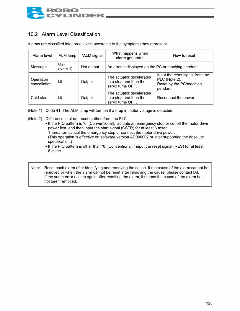
123
10.2 Alarm Level Classification Alarms are classified into three levels according to the symptoms they represent.
Alarm level ALM lamp *ALM signal What happens when alarm generates How to reset
Message Unlit (Note 1) Not output An error is displayed on the PC or teaching pendant.
Operation cancellation Lit Output
The actuator decelerates to a stop and then the servo turns OFF.
Input the reset signal from the PLC (Note 2). Reset by the PC/teaching pendant.
Cold start Lit Output The actuator decelerates to a stop and then the servo turns OFF.
Reconnect the power.
(Note 1) Code 41: The ALM lamp will turn on if a drop in motor voltage is detected. (Note 2) Difference in alarm reset method from the PLC
• If the PIO pattern is “0: [Conventional],” actuate an emergency stop or cut off the motor drive power first, and then input the start signal (CSTR) for at least 6 msec. Thereafter, cancel the emergency stop or connect the motor drive power. (This operation is effective on software version AD000007 or later supporting the absolute specification.)
• If the PIO pattern is other than “0: [Conventional],” input the reset signal (RES) for at least 6 msec.
Note: Reset each alarm after identifying and removing the cause. If the cause of the alarm cannot be removed or when the alarm cannot be reset after removing the cause, please contact IAI.
If the same error occurs again after resetting the alarm, it means the cause of the alarm has not been removed.

124
10.3 Alarm Description Output Using PIO So that the PLC can recognize the nature of each alarm that has generated, alarm description is output using the ports for completed position output signals (PM1 to PM8). Configure the system in such a way that the PLC can determine whether the output is a completed position number or alarm description based on the ON/OFF status of the alarm output signal (*ALM). Bit assignment table for alarm description ( = OFF, = ON)
∗ALM PM8 PM4 PM2 PM1 Description: Code number in ( )
x x x x Normal
Nonvolatile memory data write error (F7)
Relating to position data/parameter • Data error at execution of bank 30 (B0) • Data error at execution of bank 31 (B1)
Excitation detection error (B8)
Excessive actual speed (C0)
Relating to supply voltage • Excessive motor supply voltage (C9) • Excessive control supply voltage (CC) • Drop in control supply voltage (CE)
Overheating (CA)
Deviation overflow (D8)
Servo error (C1)
Relating to encoder disconnection • Phase-A/B disconnection detection (E8) • Phase-A disconnection detection (E9) • Phase-B disconnection detection (EA) Relating to absolute specification • ABS error 1 (ED) • ABS error 2 (EE) • ABS error 3 (EF)
CPU error (FA) FPGA error (FB)
Corrupt nonvolatile memory data (F8)

125
10.4 Alarm Description and Cause/Action
(1) Message level alarms Code Error name Cause/Action
40 Emergency stop Cause: An emergency stop condition was detected. (This is not an error.)
41 Motor voltage drop Cause: The “external cutoff relay” controller detected a motor drive-power cutoff condition where the MPI and MPO terminals are open.
(This is not an error.) (Note) If this alarm generates when the MPI and MPO terminals are
closed, an internal failure of the controller is suspected. 5A Reception overrun
5B Reception framing error
5D Header error
5E Delimiter error
7F BCC error
This alarm indicates an error during PC or teaching pendant operation or in the serial communication using the PLC’s communication module. Cause: [1] Garbage data due to the effect of noise
[2] Duplicate slave numbers when multiple controllers are controlled by serial communication
[3] The teaching pendant and PC were connected at the same time when the SIO converter was in use.
Action: [1] Adjust the wiring in a manner eliminating the effect of noise and review the installation of equipment, etc.
[2] Change the slave numbers to avoid duplication. [3] Connect only one at a given time.
61 FNCCHR, W address error
62 Operand 1 error
63 Operand 2 error
64 Operand 3 error
This alarm indicates an error in the serial communication using the PLC’s communication module. Cause: Undefined command or out-of-range data Action: Review the transmitted data and correct the format.
65 EEPROM write timeout Cause: Writing of parameter or position data to the nonvolatile memory area does not complete within 200 ms.
(This alarm will not generate in normal operation.) Action: Do not write data from the PC or teaching pendant
simultaneously while a command is being issued from the PLC.70 Movement command
during RUN-OFF Cause: A movement command was issued while the servo was OFF. Action: Issue a movement command after confirming that the servo is
ON (SRDY or PEND is ON). 73 Error reset during servo
ON Cause: An alarm reset command was sent while the servo was ON
during an operation by serial communication. (PIO commands are excluded.) Action: Send an alarm reset command after confirming that the servo
is OFF. 75 Movement command
during home return Cause: The next movement command was issued during home return. Action: Issue the next movement command after confirming that the
home return has completed (HEND is ON).

126
Code Error name Cause/Action
76 Soft reset during servo ON
Cause: A soft reset command was sent while the servo was ON during an operation by serial communication.
(PIO commands are excluded.) Action: Send a soft reset command after confirming that the servo is
OFF. 77 Movement command
during teaching Cause: A position movement command was entered from a PC or
teaching pendant while the teaching mode was selected. (Only the JOG inputs are enabled in the teaching mode.) Action: Switch to the normal mode before entering a position
movement command. (Turn OFF the MODE input signal and check if MODES is
OFF.)
78 EEPROM written during teaching
Cause: Data was written from the PC or teaching pendant simultaneously while the MODE signal was being input from the PLC (teaching mode).
Action: Do not edit data from the PC or teaching pendant simultaneously while a command is being issued from the PLC.
7A ABS data backup battery voltage low warning
Cause: The battery voltage was 4.4 V or below when the power was input.
Action: Supply the power for at least 48 hours to charge the batteries. (Moving the actuator will not affect the process of charging.)
(2) Operation-cancellation level alarms Code Error name Cause/Action
B0 Bank 30 data error Cause: Data in the parameter area is outside the input range or invalid. (This alarm will not generate in normal parameter input
operation, but may occur during serial communication using the PLC’s communication module.)
Action: Transfer data after confirming that the parameter values are valid.
B1 Bank 31 data error Cause: [1] A movement command was issued by selecting a number to which no position data was registered.
[2] Position data value exceeds the soft limit setting. [3] The timing of start signal is varied or too early.
Action: [1] Revise the sequence in such a way that unregistered position numbers will not be selected.
[2] Change the position data to a value inside the soft limit settings.
[3] The minimum timer setting may not be recognized depending on the PLC. Pay attention to the timer setting.
BE Home return timeout Cause: Home return does not complete within the period set in the applicable system parameter after the start of home return operation.
(This alarm will not generate in normal operation.) Action: The combination of controller and actuator may be wrong. Please contact IAI.

127
Code Error name Cause/Action
C0 Excessive actual speed Cause: This alarm indicates that the motor speed exceeded the maximum speed set in the applicable system parameter.
This alarm will not generate in normal operation, but may occur in the following conditions: [1] Large actuator slide resistance in certain area, or [2] Instantaneous increase in load due to application of
external force, which may cause the load to decrease and actuator to move rapidly before a servo error is detected.
Action: Check for abnormality in the assembly condition of mechanical parts.
If the actuator is suspected to be the cause, please contact IAI.
C1 Servo error This alarm indicates that after receiving a movement command the motor is unable to operate for two seconds or more before reaching the target position. Cause: [1] Loose or disconnected motor-relay cable connector
[2] Brake cannot be released on a controller equipped with brake.
[3] Large load due to application of external force [4] Large slide resistance of the actuator itself
Action: [1] Check the wiring condition of the motor relay cable. [2] Check the wiring condition of the brake cable, and also
turn on/off the brake release switch to see if the brake makes “click” sounds.
[3] Check for abnormality in the assembly condition of mechanical parts.
[4] If the load is normal, cut off the power and move the actuator by hand to check the slide resistance.
If the actuator is suspected to be the cause, please contact IAI.
C9 Excessive motor supply voltage
This alarm indicates that the motor supply voltage is excessive (24V + 20%: 28.8V or more). Cause: [1] High voltage of the 24-V input power supply
[2] Faulty part inside the controller Action: Check the voltage of the input power supply. If the voltage is normal, please contact IAI.
CA Overheating This alarm indicates that the temperature around the power transistor in the controller is too high (95°C or higher). Cause: [1] High temperature around the controller
[2] In the case of the dedicated controller for the high-thrust type, the radiating fan may be faulty.
[3] Faulty part inside the controller Action: [1] Lower the ambient temperature of the controller.
[2] Refer to 11, “Function Check and Replacement of the Radiating Fan,” to check if the fan is faulty.
If the fan is faulty, replace the fan. If taking the actions in [1] and [2] does not solve the problem,
please contact IAI. CC Overvoltage of control
power supply This alarm indicates that the voltage of the 24-V input power supply is excessive (24V + 20%: 28.8V or more). Cause: [1] High voltage of the 24-V input power supply
[2] Faulty part inside the controller Action: Check the voltage of the input power supply. If the voltage is normal, please contact IAI.

128
Code Error name Cause/Action
CE Drop in control supply voltage
This alarm indicates that the voltage of the 24-V input power supply has dropped (24V – 20%: 19.2V or less). Cause: [1] Low voltage of the 24-V input power supply [2] Faulty part inside the controller Action: Check the voltage of the input power supply. If the voltage is normal, please contact IAI.
ED Absolute encoder error (1)
Cause: [1] The battery voltage was 4.4 V or below when the power was input.
[2] The current position has changed due to the effect of vibration, etc., when the power was input.
Action: If code “7A” is displayed after the reset, the battery voltage is low. Charge the batteries for at least 48 hours. If “7A” is not displayed, turn off the power, and then turn it on again by making sure the actuator does not vibrate. Execute an absolute reset. (Note)
EE Absolute encoder error (2)
The absolute counter data in the FPGA is damaged. Cause: [1] The power was input for the first time after connecting the
batteries. (This message is always displayed at the initial power on.)
[2] The parameter for home return direction or home return offset was changed.
[3] The power supply was cut off for a prolonged period and the battery voltage has dropped to a level at which the absolute counter data can no longer be retained.
[4] The encoder cable or battery cable became open while the power supply was cut off.
Action: If [4] is suspected, check the connectors and cables for loose connections.
If the battery voltage is low, keep the power supplied for at least 48 hours to charge the battery.
Execute an absolute reset. (Note)
EF Absolute encoder error (3)
Cause: The actuator was moved by hand and the motor speed exceeded 150 rpm while the power supply was cut off.
Action: Be careful not to move the actuator while the power is cut off. Execute an absolute reset. (Note)
F7 EEPROM write error A current-position write signal (PWRT) was input in the teaching mode when the controller was unable to receive the signal. Cause: [1] The signal was input when home return was not yet
completed. [2] The signal was input during jogging.
Action: [1] Input the signal after confirming that home return has completed (HEND is ON).
[2] Input the signal after confirming that the JOG button is not pressed or the actuator is stopped (MOVE is OFF).
(Note) How to execute an absolute reset when an ED, EE or EF error is present
[1] Reset the alarm (clear the error message) to turn the *ALM signal ON again. [2] Perform home return. These steps can be performed using the teaching pendant or PC or by issuing applicable commands from the PLC. You can use any of these three methods, but be sure to perform the above steps. Refer to 7.1, “How to Start.”

129
(3) Cold-start level alarms
Code Error name Cause/Action
B8 Pole sense error This controller will conduct excitation phase detection when the servo is first turned ON after the power was input. This alarm indicates that the specified encoder signal level cannot be detected after 100 ms of excitation. Cause: [1] Loose or disconnected motor-relay cable connector
[2] Brake cannot be released on a controller equipped with brake.
[3] Large motor load due to application of external force [4] Power was input when the actuator was contacting a
mechanical end. [5] Large slide resistance of the actuator itself
Action: [1] Check the wiring condition of the motor relay cable. [2] Check the wiring condition of the brake cable, and also turn
on/off the brake release switch to see if the brake makes “click” sounds.
[3] Check for abnormality in the assembly condition of mechanical parts.
[4] Move the actuator away from the mechanical end and then reconnect the power.
[5] If the load is normal, cut off the power and move the actuator by hand to check the slide resistance.
If the actuator is suspected to be the cause, please contact IAI.D8 Deviation overflow The position deviation counter has overflowed.
Cause: [1] The speed dropped during movement due to the effect of an external force, etc.
[2] The pole sense detection operation after power on is unstable.
Action: [1] Check the load conditions—such as whether the load is contacting a surrounding object or the brake is disengaged—and then correct the abnormality, if any
[2] An overload condition is suspected, so review the load weight. Reconnect the power and then execute home return.
E8 Phase-A/B disconnection detection
E9 Phase-A disconnection detection
EA Phase-B disconnection detection
Encoder signals cannot be detected correctly. Cause: [1] Loose or disconnected encoder-relay cable connector
[2] Loose or disconnected actuator-end connector of the supplied cable
[3] The encoder relay cable connector was plugged in after the battery connector (absolute specification).
[4] If a high-thrust rod-type actuator is used together with an actuator of other type, the encoder relay cables may be connected wrongly.
Action: Check the connection condition of the encoder relay cable and conduct continuity check. If the results are normal, please contact IAI.
If [3] is the cause, plug in the encoder relay cable connector, and then plug in the battery connector.
If [4] is suspected, check the model numbers of the encoder relay cables and connect the relay cables correctly.
Cable for high-thrust rod type: CB-RFA-PA*** Cable for other actuator type: CB-RCP2-PA***

130
Code Error name Cause/Action
F8 Damaged nonvolatile memory
Abnormal data was detected during the nonvolatile memory check after starting. Cause: [1] Faulty nonvolatile memory
[2] The memory has been rewritten more than 100,000 times. (The nominal rewrite limit of the nonvolatile memory is
around 100,000 times.) Action: If the alarm generates again after reconnecting the power,
please contact IAI. FA CPU error The CPU is not operating properly.
Cause: [1] Faulty CPU [2] Malfunction due to noise
Action: If the alarm generates again after reconnecting the power, please contact IAI.
FB FPGA error The FPGA (gate array) of the absolute-specification controller is not operating properly. Cause: [1] Malfunction due to the effect of noise, etc. [2] Faulty FPGA [3] Defective board installation inside the controller Action: Reconnect the power. If the error persists, investigate possible noise sources. If the cause cannot be specified, please contact IAI.

131
10.5 Messages Displayed during Operation Using the Teaching Pendant or PC
Software This section explains the warning messages that may be displayed during operation using the teaching pendant or PC software.
Code Error name Cause/Action
112 Invalid data An inappropriate value was entered in a parameter. (Example) 9601 was entered as the serial communication speed by mistake. Enter an appropriate value again.
113 114
Value too small Value too large
The entered value is smaller than the setting range. The entered value is larger than the setting range. Refer to the actuator specifications or parameter table and enter an appropriate value again.
115 Home return non-completion The current position was written when home return was not yet completed. Execute home return again.
116 Last position data Data already exists in the last position area of the position table when new data is added. Clear or delete the current last position data first.
117 No movement data Target position is not set under the selected position number. Enter the target position first.
11E Paired data mismatch The values indicating the magnitude relationship of a pair of data are inappropriate. (Example) The same value was entered in both the parameters for + and – soft
limits. Enter appropriate values again.
11F Absolute position too small The minimum movement toward the target position is determined by the lead length of the drive system and resolution of the encoder. This message indicates that the entered target value is smaller than the minimum movement. (Example) If the lead length is 20 mm, the encoder’s resolution is 800 pulses
and accordingly the minimum movement becomes 20 ÷ 800 = 0.025 mm/pulse.
In this case, this message will be displayed if 0.02 mm is entered as the target position.
121 Push & hold search end over
The final position in push & hold operation exceeds the soft limit. This has no negative effect if the actuator contacts the load. If the actuator misses the load, however, the soft limit will be reached and thus this message is displayed as a warning. Change either the target position or positioning band.
122 Multiple axes connected at assignment
Address was assigned when multiple axes were connected. Assign each address only when one axis is connected.
180 181 182
Address change OK Controller initialization OK Home change all clear
These messages are displayed to confirm operation. (They don’t indicate an operation error or other abnormality.)
201 Emergency stop An emergency stop condition was detected. (This is not an error.)
20A Servo OFF during operation This message indicates that the servo ON signal (SON) was turned OFF by the PLC while the actuator was moving, and that the servo turned OFF and the movement was disabled as a result.

132
Code Error name Cause/Action
20C CSTR-ON during operation This message indicates that the start signal (CSTR) was turned ON by the PLC while the actuator was moving, and that duplicate movement commands occurred as a result.
20D STP-OFF during operation This message indicates that the pause signal (*STP) was turned OFF by the PLC while the actuator was moving, and that the movement was disabled as a result.
20E Soft limit over This message indicates that a soft limit was reached.
20F Push & hold missed-contact detection
This message indicates that the actuator didn’t contact the load during push & hold operation. Check the load condition and review the target position/positioning band settings.
210 HOME-ON during operation This message indicates that the home return signal (HOME) was turned ON by the PLC while the actuator was moving, and that duplicate movement commands occurred as a result.
211 JOG-ON during operation This message indicates that the jog signal (JOG) was turned ON by the PLC while the actuator was moving, and that duplicate movement commands occurred as a result.
301 302 304 305 306 308 30A 30B
Overrun error (M) Framing error (M) SCIR-QUE OV (M) SCIS-QUE OV (M) R-BF OV Response timeout (M) Packet R-QUE OV Packet S-QUE OV
These messages indicate an error in the serial communication with the controller. Cause: [1] Garbage data due to the effect of noise
[2] Duplicate slave numbers when multiple controllers are controlled by serial communication
Action: [1] Adjust the wiring in a manner eliminating the effect of noise and review the installation of equipment, etc.
[2] Change the slave numbers to avoid duplication. If the message is still displayed after taking the above actions, please contact IAI.
307 Memory command refused This message indicates that the command was refused in the serial communication with the controller.
309 Write address error This message indicates that an indeterminate WRITE address error occurred in the serial communication with the controller. These conditions do not occur in normal operation. Should they occur, record the entire error list before cutting off the power for use in the cause investigation. Also contact IAI.
30C No connected axis This message indicates that no controller address is recognized. Cause: [1] The controller is not operating properly.
[2] Only the supplied communication cable (SGA/SGB) is disconnected.
[3] If a SIO converter is used, 24V is supplied to the converter but the link cable is not connected.
[4] The ADRS switch settings are duplicated by mistake when multiple controllers are linked.
Action: [1] Check if the RDY lamp on the controller is lit. If the lamp is not lit, the controller is faulty.
[2] If a spare teaching pendant is available, replace the current pendant with the spare unit, or with a PC, and see if the message disappears.
[3] Supply power after connecting the link cable between the converter and controller.
[4] Make sure the ADRS switch settings are not duplicated. If the message is still displayed after taking the above actions, please contact IAI.

133
10.6 Specific Problems
I/O signals cannot be exchanged with the PLC. Cause: [1] The 24-V I/O power supply is connected in reverse. (This will not affect the input circuits, but the output circuits will be damaged.) [2] If the problem is with an output circuit, a circuit component may have been damaged due
to a large load that caused the current flowing into the circuit to exceed the maximum current.
[3] Contact failure in the connector or relay terminal block on the PLC end. [4] Contact failure between the female pins in the flat cable connector and the male pins on
the controller due to expanded female pins. Action: Check the connection condition of the power supply and connector, as well as the load on the
output side. If the cause is identified as [1] or [2], the controller must be replaced. If there is a possibility of
[4], the flat cable must be replaced. Please contact IAI.
Note: When performing a continuity check of the flat cable, pay due attention not to expand the female pins in the connector. It may cause contact failure and disable normal operation of the controller.
The RDY lamp does not illuminate after the power is input.
Cause: [1] Reverse connection of the 24-V power supply [2] Faulty controller If the power supply is connected properly, probably the controller is faulty. Please contact IAI.
(Note) If the 24-V power supply is connected in reverse, the controller may not fail immediately but its service life will likely be shortened.
Only the RDY lamp illuminates when the servo ON signal is input after the power was input.
(The servo does not turn ON.) Cause: [1] Contact failure of the flat cable [2] Faulty controller Check the servo ON signal (SON) on the I/O monitor screen of the PC or teaching pendant. If the signal is input, probably the controller is faulty. Please contact IAI.
Both the RDY lamp and ALM lamp illuminate when the power is input.
(An alarm is present, or an emergency stop has been actuated or the motor power is cut off.) Check which of the alarm signal (*ALM) and emergency-stop signal (*EMGS) is output on the I/O monitor screen of the PC or teaching pendant. If the alarm signal is output, check the description of the error and remove the cause. If the emergency-stop signal is output, check the following items: [1] Is the emergency-stop switch on the operation panel pressed? Also confirm that the necessary
interlocks are released. [2] Is the emergency-stop switch on the teaching pendant pressed? [3] Is the PORT switch turned ON when neither teaching pendant nor PC is connected? [4] If multiple controllers are connected, are the crossover wires connected correctly? If the controller is of the external cutoff relay type, check the safety circuit.

134
Home return ends in the middle in a vertical application. Cause: [1] The load exceeds the rating. [2] The ball screw is receiving torsional stress due to the affixing method of the actuator,
tightening of bolts only on one side, etc. [3] The slide resistance of the actuator itself is large. Action: [1] Increase the value set in parameter No. 13 (Current-limiting value during home return). Increasing this value will cause the home return torque to increase, so do not increase the
parameter setting above 75%. [2] Loosen the fixing bolts and check if the slider moves smoothly. If the slider moves smoothly, review the affixing method and bolt tightening condition. [3] If the slide resistance of the actuator itself is large, please contact IAI.
Noise occurs during downward movements in a vertical application.
Cause: The load exceeds the rating. Action: [1] Decrease the speed. [2] Decrease the value set in the parameter No. 7 (Servo gain number). Do not decrease the
parameter setting below “3.”
Vibration occurs when the actuator is stopped. Cause: The slider is receiving an external force. Action: If the external force cannot be removed, increase the value set in parameter No. 12 (Current-
limiting value at standstill during positioning). Increasing this value will cause the holding torque at standstill to increase, so do not increase
the parameter setting above 70%.
The actuator overshoots when decelerated to a stop. Cause: The load inertia is high due to an inappropriate balance of load and deceleration. Action: Decrease the acceleration/deceleration setting.
The home and target positions sometimes shift.
Cause: [1] The encoder waveform is disturbed by the effect of noise. [2] In the case of a rod-type actuator, the non-rotation accuracy increased due to application
of rotating moment to the rod. Action: [1] Check if the grounding is implemented correctly. Also check for any equipment being a
potential noise source. [2] The actuator may have to be replaced in some cases. Please contact IAI.
The speed is slow during push & hold operation.
Cause: The set current-limiting value is low with respect to the load and slide resistance. Action: Increase the current-limiting value for push & hold operation.

135
The actuator moves only a half of, or twice as much as, the specified movement. Cause: [1] The combination of controller and actuator is wrong. The lead length of the ball screw varies depending on the actuator type, so a wrong
combination will cause the movement and speed to change. [2] Factory setting error at IAI Action: [1] If multiple actuators of different types must be used, confirm using the identification labels,
etc., that the correct actuator is connected to the controller. [2] Please contact IAI.
A servo error occurred while the actuator was moving (ROBO Gripper).
Cause: The load was not positioned properly and contacted the finger attachment in the positioning mode.
Action: Adjust the starting position of push action and the thickness of finger attachment (including buffer material) by considering a possible offset of load position, so that the load can be clamped properly in the push & hold mode.
Immediately after recovery from the error, the feed mechanism may still be locked. Be sure to turn the open/close screw to loosen each finger attachment before resetting the alarm.]
Note: If the servo ON signal is disabled or the alarm is reset while the servo ON signal is still
ON, the servo will remain ON. If the open/close screw is turned in this condition, the screw will return automatically and
the lock cannot be released. Therefore, reissuing a movement command will cause the alarm to generate again.
[Two-finger type] [Three-finger type] Remove the load by removing one finger attachment, and then turn the open/close screw clockwise.
Open/close screw Turn the screw counterclockwise using a flathead screwdriver.
OP
EN
Remove one finger attachment.
Open/close screw
Turn clockwise.
Open direction

136
Abnormal operation results when the servo is turned ON after the power ON. Cause: Excitation phase detection was not performed correctly when the servo was turned ON,
because one of the following conditions existed when the power was input: [1] The slider or rod was contacting the mechanical end. [2] The load was being pushed by a strong external force.
Action: [1] Check if the slider or rod is contacting the mechanical end. If the slider/rod is contacting the mechanical end, move it away from the mechanical end. If the actuator is equipped with a brake, move the slider/rod after turning ON the brake release switch to forcibly release the brake. At this time, exercise caution not to allow the load to drop suddenly due to its own weight. Your hand may be caught by the dropped load or the robot hand or load itself may be damaged. If the actuator cannot be moved by hands, check the direction of excitation phase signal detection and change the detection direction, if necessary. For details, refer to 8.3.2, “Parameters Relating to the Actuator Operating Characteristics.”
[2] Check if the load is contacting any surrounding part. If the load is contacting any surrounding part, provide a clearance of 1 mm or more from the applicable part.
If the checks in [1] and [2] did not find any problem, please contact IAI.
The ALM lamp blinks when the power is cut off. Cause: The battery voltage of the absolute specification controller has dropped to approx. 4.1 V or
below. Action: Turn on the power and keep it on for at least 48 hours to charge the battery.

137
11. Function Check and Replacement of the Radiating Fan The large-capacity type (RCP2-CF-***) has a built-in radiating fan. To check the function of this fan and replace the fan when found faulty, follow the steps explained below. 1) Disconnect all connectors and cables from the controller, and then remove the fan unit. 2) Remove the resin case. • The hooks on the mounting base plate are secured in the notches provided in the resin case. Pull the
case outward until the hooks are released, and then push up the mounting base plate.
Remove everything except for the MPI/MPO jumper wires.
• Pull out the resin case.
Enlarged view of “A”

138
3) Check if the fan is normal. (Note) To prolong the life of the fan, the ambient temperature of the power transistor is detected using a
temperature sensor. The fan will start when the detected temperature rises to 60°C or above. If the temperature drops to 50°C or below, the fan will stop.
For operation check, the fan is designed to operate for approx. 2 seconds when the power is turned on.
4) If the fan is faulty, turn off the power and then replace the fan.
[1] Remove the fan.
[2] Affix the new fan using the pan-head screws, and then plug in the connector. (Reference) Tightening torque of pan-head screw: 61.5 N cm (6.27 kgf cm)
[3] To make sure, turn on the power to confirm that the fan will operate.
5) Turn off the power, and then disconnect the power cable. 6) Install the resin case.
Secure the hooks on the mounting base plate in the notches in the resin case. 7) Plug in all connectors and cables to their original positions.
Connect the power cable to the 24V and N terminals on the power terminal block.
Turn on the power to see if the fan operates. If the fan is normal, it will operate for approx. 3 seconds. If the fan is faulty, it will not operate.
Remove the pan-head screws (M3 x 15, 2 pcs) affixing the fan. Removed fan
Pull out the connector by hand.
Check method:
[1]
[2]

139
Appendix
* Appendix List of Supported Actuator Specifications
Slider, ball-screw drive type
(Note 1) The figure in the elongated circle indicates the maximum speed for the applicable strokes. The maximum speeds in vertical applications are shown in ( ).
(Note 2) The load capacity is based on operation at the rated acceleration.
Slider, belt-drive type
Model Stroke (mm) and maximum speed (mm/sec) (Note 1)
Load capacity (Note 2) Rated acceleration
Horizontal Vertical Horizontal Vertical
Mot
or s
traig
ht
Mot
or re
vers
ed
Hig
h sp
eed
Wat
er-
proo
f
Model Stroke (mm) and maximum speed (mm/sec)
Load capacity Rated acceleration
Horizontal Vertical Horizontal Vertical

140
Appendix
Rod type
(Note 1) The figure in the elongated circle indicates the maximum speed for the applicable strokes. The maximum speeds in vertical applications are shown in ( ).
(Note 2) The load capacity is based on operation at the rated acceleration.
Gripper Model Stroke Maximum gripping force Maximum speed Lead Rated acceleration
RCP2-GRS-I-PM-1-10-P1 10 mm (one finger: 5 mm) 21 N 33.3 mm/s (one finger) 1.0 mm 0.3G
Two
finge
rs
RCP2-GRM-I-PM-1-14-P1 14 mm (one finger: 7 mm) 80 N 36.7 mm/s (one finger) 1.1 mm 0.3G RCP2-GR3SS-I-PM-30-10-P1 10 mm (one finger: 5 mm) 23 N 40 mm/s (one finger) 2.5 mm 0.2G RCP2-GR3SM-I-PM-30-14-P1 14 mm (one finger: 7 mm) 120 N 50 mm/s (one finger) 3.0 mm 0.2G RCP2-GR3LS-I-PM-30-19-P1 19° 17 N 200°/s (one finger) 12° 0.2G Th
ree
finge
rs
RCP2-GR3LM-I-PM-30-19-P1 19° 62 N 200°/s (one finger) 12° 0.2G
Rotary Model Swing angle Maximum torque Maximum speed Gear ratio Rated acceleration
RCP2-GTB-I-PM-20-330-P1 330° 1.1 N m 600°/s 1/20 0.3G
Verti
cal
RCP2-GTB-I-PM-30-330-P1 330° 1.7 N m 400°/s 1/30 0.3G
RCP2-GTC-I-PM-20-330-P1 330° 1.1 N m 600°/s 1/20 0.3G
Flat
RCP2-GTC-I-PM-30-330-P1 330° 1.7 N m 400°/s 1/30 0.3G
Model Stroke (mm) and maximum speed (mm/sec) (Note 1) Load capacity (Note 2) Rated acceleration
Horizontal Vertical Horizontal Vertical
Sta
ndar
d S
plas
h-pr
oof
Sin
gle
guid
e D
oubl
e gu
ides
H
igh
thru
st

141
Appendix
Correlation diagrams of speed and load capacity of the slider, motor-straight type
(Note) In the above graphs, the figure after each model type indicates a lead.
Hig
h-sp
eed
type
M
ediu
m-s
peed
type
Lo
w-s
peed
type
Horizontal installation Vertical installation
Load
cap
acity
(kg)
Lo
ad c
apac
ity (k
g)
Load
cap
acity
(kg)
Speed (mm/sec) Speed (mm/sec)
Speed (mm/sec) Speed (mm/sec) Speed (mm/sec) Speed (mm/sec)
Load
cap
acity
(kg)
Lo
ad c
apac
ity (k
g)
Load
cap
acity
(kg)

142
Appendix
Correlation diagrams of speed and load capacity of the slider, motor-reversed type
(Note) In the above graphs, the figure after each model type indicates a lead.
Hig
h-sp
eed
type
M
ediu
m-s
peed
type
Lo
w-s
peed
type
Horizontal installation Vertical installation Lo
ad c
apac
ity (k
g)
Load
cap
acity
(kg)
Lo
ad c
apac
ity (k
g)
Speed (mm/sec) Speed (mm/sec)
Speed (mm/sec) Speed (mm/sec) Speed (mm/sec) Speed (mm/sec)
Load
cap
acity
(kg)
Lo
ad c
apac
ity (k
g)
Load
cap
acity
(kg)

143
Appendix
Correlation diagrams of speed and load capacity of the slider, high-speed ball-screw type
(Note) The load capacity varies depending on the acceleration.
(Note) The load capacity varies depending on the acceleration.
Correlation diagram of speed and load capacity of the slider, belt type
Horizontal installation Vertical installation
Horizontal installation Vertical installation
Horizontal installation
Load
cap
acity
(kg)
Lo
ad c
apac
ity (k
g)
Speed (mm/sec) Speed (mm/sec)
Speed (mm/sec) Speed (mm/sec)
Load
cap
acity
(kg)
Lo
ad c
apac
ity (k
g)
Load
cap
acity
(kg)
Speed (mm/sec)

144
Appendix
Correlation diagrams of speed and load capacity of the rod, standard type
(Note) In the above graphs, the figure after each model type indicates a lead. (Note 1) The graphs under “Horizontal installation” assume use of an external guide(s).
Hig
h-sp
eed
type
M
ediu
m-s
peed
type
Lo
w-s
peed
type
Horizontal installation (Note 1) Vertical installation Lo
ad c
apac
ity (k
g)
Load
cap
acity
(kg)
Lo
ad c
apac
ity (k
g)
Speed (mm/sec) Speed (mm/sec)
Speed (mm/sec) Speed (mm/sec) Speed (mm/sec) Speed (mm/sec)
Load
cap
acity
(kg)
Lo
ad c
apac
ity (k
g)
Load
cap
acity
(kg)

145
Appendix
Correlation diagrams of speed and load capacity of the single-guide type
(Note) In the above graphs, the figure after each model type indicates a lead.
Hig
h-sp
eed
type
M
ediu
m-s
peed
type
Lo
w-s
peed
type
Horizontal installation Vertical installation Lo
ad c
apac
ity (k
g)
Load
cap
acity
(kg)
Lo
ad c
apac
ity (k
g)
Speed (mm/sec) Speed (mm/sec)
Speed (mm/sec) Speed (mm/sec) Speed (mm/sec) Speed (mm/sec)
Load
cap
acity
(kg)
Lo
ad c
apac
ity (k
g)
Load
cap
acity
(kg)

146
Appendix
Correlation diagrams of speed and load capacity of the double-guide type
(Note) In the above graphs, the figure after each model type indicates a lead.
Hig
h-sp
eed
type
M
ediu
m-s
peed
type
Lo
w-s
peed
type
Horizontal installation Vertical installation
Load
cap
acity
(kg)
Lo
ad c
apac
ity (k
g)
Load
cap
acity
(kg)
Speed (mm/sec) Speed (mm/sec)
Speed (mm/sec) Speed (mm/sec) Speed (mm/sec) Speed (mm/sec)
Load
cap
acity
(kg)
Lo
ad c
apac
ity (k
g)
Load
cap
acity
(kg)

147
Appendix
Correlation diagrams of speed and load capacity of the dust-proof/splash-proof type
(Note) In the above graphs, the figure after each model type indicates a lead. (Note 1) The graphs under “Horizontal installation” assume use of an external guide(s). (Note 2) If the actual payload corresponds to the maximum load capacity for the applicable speed, the
actuator may overshoot due to vibration. Select an appropriate payload by providing an allowance of 70% or so.
Hig
h-sp
eed
type
M
ediu
m-s
peed
type
Lo
w-s
peed
type
Horizontal installation (Note 1) Vertical installation (Note 2) Lo
ad c
apac
ity (k
g)
Load
cap
acity
(kg)
Lo
ad c
apac
ity (k
g)
Speed (mm/sec) Speed (mm/sec)
Speed (mm/sec) Speed (mm/sec) Speed (mm/sec) Speed (mm/sec)
Load
cap
acity
(kg)
Lo
ad c
apac
ity (k
g)
Load
cap
acity
(kg)
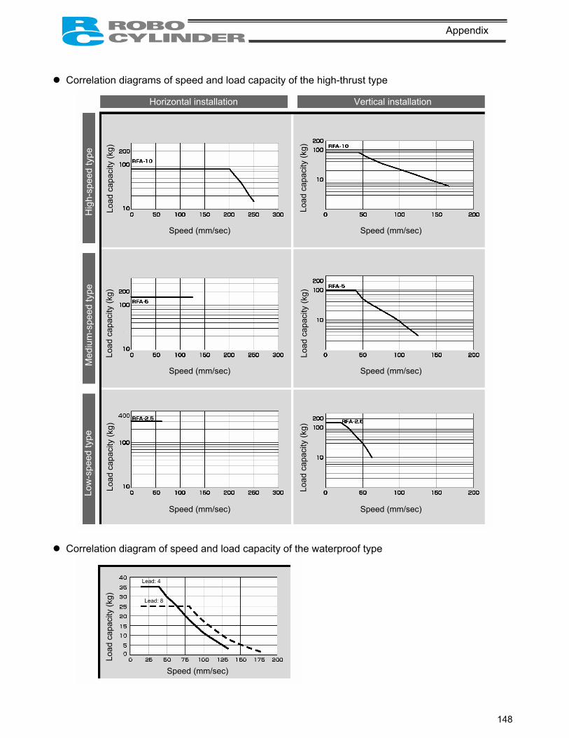
148
Appendix
Correlation diagrams of speed and load capacity of the high-thrust type
Correlation diagram of speed and load capacity of the waterproof type
Hig
h-sp
eed
type
M
ediu
m-s
peed
type
Lo
w-s
peed
type
Horizontal installation Vertical installation
Load
cap
acity
(kg)
Lo
ad c
apac
ity (k
g)
Load
cap
acity
(kg)
Speed (mm/sec) Speed (mm/sec)
Speed (mm/sec) Speed (mm/sec)
Speed (mm/sec) Speed (mm/sec)
Load
cap
acity
(kg)
Lo
ad c
apac
ity (k
g)
Load
cap
acity
(kg)
Load
cap
acity
(kg)
Speed (mm/sec)
Lead: 4
Lead: 8

149
Appendix
Example of Basic RCP2 Positioning Sequence
Given below is an example of basic sequence for creating a positioning sequence using the RCP2. indicates PIO signals of the RCP2 controller.
(Completed-position decoding circuit) Position complete
(Must be longer than the PLC’s scan time.)
Completed position codes
PM1 PM2 PM4 PM8
PM1 PM2 PM4 PM8
PM1 PM2 PM4 PM8
PM1 PM2 PM4 PM8
PM1 PM2 PM4 PM8
Timer 1
Timer 1
Timer 1
Timer 1
Timer 1
Waiting for the completed position to be read PEND
Completed position 1
Completed position 2
Completed position 3
Completed position 4
Completed position 5
Timer 1
A
B
C
D
E
Create for the number of positions.
(Positioning circuit for position 1: When position 1 is set as the home)Home return request
Home return request
Home-return start pulse
Auxiliary home-return start pulse
G
F
G
F
G
Positioning start request to position 1 I
H
I H
Positioning start request to position 1
I
Positioning start pulse to position 1 (home)
Auxiliary positioning start pulse to position 1 (home)
The positioning start request signal is converted to pulse in such a way that one start signal is issued for one positioning operation.
Home return completion PEND F HEND
Auxiliary positioning start for position 1 (home) J K
(E) H
J
J PEND L K
K
K A (O)
L
L
Start check for position 1 (home)
Auxiliary start signal for next positioning
Check if positioning to the specified position has completed.
Completion of positioning to position 1 (home)
Current positioning completed position

150
Appendix
Current positioning completed position
(Positioning circuit for position 2)
Positioning start request to position 2 N
N
M
M
N
Positioning start request to position 2
(A) M P
O
O PEND Q
Auxiliary start signal for next positioning
P
Q
P B
O
P
Q
Positioning start pulse to position 2
Auxiliary positioning start for position 2
Start check for position 2
Completion of positioning to position 2
If a measure is taken to identify the current position in the sequence in case the sequence stops in the middle, as implemented in this circuit, even when a problem occurs the cause can be identified more easily.
Create for the number of positions. (Command position number output encoding circuit)
J O
R
Auxiliary start position for positioning to other position
Set signal for other position S
R
S
Position 1 set
Position 2 set R
Auxiliary start position for positioning to other position J O
S The command position is held until positioning to other position is started, in order to prevent the
command position from changing during positioning.
Create for the number of positions.
Set signal for other position
Auxiliary positioning start pulse to position 2

151
Appendix
Position 3 set signal
S
R
Position 5 set signal
Command position 1
Command position 2
PC1
PC2
Position 6 set signal
Position 3 set signal
PC4
PC8
Command position 4
Command position 8
(Start signal circuit)
J Timer 2 Waiting for start
O
Start command for positioning to other position
Timer 2
Start signal
5 msec or more (Must be longer than the PLC’s scan time.)
CSTR

152
Appendix
Recording of Position-Data Table
Recorded date:
No. Position [mm] Speed [mm/sec]
Acceleration/ deceleration [G] Push [%] Positioning band
[mm] Acceleration only
MAX 0
1
2
3
4
5
6
7
8
9
10
11
12
13
14
15

153
Appendix
Valid only when [64-point positioning] is selected
No. Position [mm] Speed [mm/sec]
Acceleration/ deceleration [G] Push [%] Positioning band
[mm] Acceleration only
MAX 16 17 18 19 20 21 22 23 24 25 26 27 28 29 30 31 32 33 34 35 36 37 38 39 40 41 42 43 44 45 46 47 48 49 50 51 52 53 54 55 56 57 58 59 60 61 62 63

154
Appendix
Recording of Parameters
Recorded date:
Category a: Parameter relating to the actuator stroke range b: Parameter relating to the actuator operating characteristics c: Parameter relating to the external interface d: Servo gain adjustment
No. Category Name Unit Recorded data 1 a Zone boundary 1+ mm 2 a Zone boundary 1– mm 3 a Soft limit+ mm 4 a Soft limit– mm
5 a Home return direction (0: [Reverse]/1: [Forward]) -
6 b Push & hold stop judgment period msec 7 d Servo gain number - 8 b Default speed mm/sec 9 b Default acceleration/deceleration G
10 b Default positioning band (in-position) mm 11 b Default acceleration only MAX flag - 12 b Current-limiting value at standstill during positioning % 13 b Current-limiting value during home return % 14 (Reserved for future extension)
15 c Pause input disable selection (0: [Enable]/1: [Disable]) -
16 c Serial communication speed bps 17 c Minimum delay time for slave transmitter activation msec 18 (Reserved for future extension) 19 (Reserved for future extension) 20 (Reserved for future extension)
21 c Servo ON input disable selection (0: [Enable]/1: [Disable]) -
22 a Home return offset mm 23 a Zone boundary 2+ mm 24 a Zone boundary 2– mm 25 c PIO pattern selection - 26 b PIO jog speed mm/sec 27 c Movement command type (0: [Level]/1: [Edge]) -
28 b Direction of excitation phase signal detection (0: [Reverse]/1: Forward]) -

Catalog No.: RCP2C-MJ0136-10A-Feb0906-1
Head Office: 2690 W. 237th Street, Torrance, CA 90505 TEL (310) 891-6015 FAX (310) 891-0815
Chicago Office: 1261 Hamilton Parkway, Itasca, IL 60143 TEL (630) 467-9900 FAX (630) 467-9912
New Jersey Office: 7 South Main St., Suite-F, Marlboro, NJ 07746 TEL (732) 683-9101 FAX (732) 683-9103
Website: www.intelligentactuator.com
Ober der Röth 4, D-65824 Schwalbach am Taunus, Germany TEL 06196-88950 FAX 06196-889524
The information contained in this document is subject to change without notice for the purpose of product improvement. Copyright © 2005. Nov. IAI Corporation. All rights reserved.


