R&D proposal for an Endcap TOF and TRD for Identifying electrons at EIC PRINCIPAL INVESTIGATORS Zhangbu Xu (BNL) [email protected]Ming Shao (USTC/China) [email protected]PHONE 631-344-3955 DEPARTMENT/DIVISION BNL/USA and USTC/China DATE 12/12/2013 INVESTIGATORS Tonko Ljubicic, Bob Scheetz, Lijuan Ruan, Zhangbu Xu (BNL) Gerard Visser, Indiana University CEEM Cheng Li, Hongfang Chen, Ming Shao (USTC/China) TITLE OF PROPOSAL GEM based TRD for Identifying electrons at EIC PROPOSAL TERM (month/year) From 06/2013 Through 05/2014 SUMMARY OF PROPOSAL Resubmission with status report and no additional fund request (page 37--) Description of Project: Electron identification is crucial in an EIC detector for identifying the out-going scattered electrons from the incident electron beam. Furthermore, precise kinematics from these electrons are necessary to determine the (x, Q 2 ) of the interaction. We propose to study the combined functionality of a Time-of-Flight detector (TOF) and a Transition Radiation Detector (TRD) at forward direction (-3<η<-1) behind low-material tracking detector to provide electron identification with high hadron rejection (~>10 3 ) over a wide momentum range (0.2 GeV/c<p<~10 GeV/c). In addition, the configuration also provides start time for the produced hadrons in TOF detectors in other locations and additional precise tracking points for hadron reconstruction in the case that the struck particle is a hadron. We propose an R&D project to use GEM detector with Xe+CO 2 for detection of transition radiation and multi-gap resistive plate chamber as TOF detector. The goals are: a) study the GEM readout performance for dE/dx (TR) signals and its position resolution in the TPC-style readout with 3-4cm ionization chamber; b) investigate different GEM configuration (regular GEM vs Thick GEM) and its impact on tracking and dE/dx. Expected Results: 1
Transcript
R&D proposal for an Endcap TOF and TRD for Identifying electrons at EIC
DEPARTMENT/DIVISION BNL/USA and USTC/China DATE 12/12/2013
INVESTIGATORS Tonko Ljubicic, Bob Scheetz, Lijuan Ruan, Zhangbu Xu (BNL) Gerard Visser, Indiana University CEEM Cheng Li, Hongfang Chen, Ming Shao (USTC/China)
TITLE OF PROPOSAL GEM based TRD for Identifying electrons at EIC
PROPOSAL TERM (month/year) From 06/2013 Through 05/2014
SUMMARY OF PROPOSAL Resubmission with status report and no additional fund request (page 37--) Description of Project: Electron identification is crucial in an EIC detector for identifying the out-going scattered electrons from the incident electron beam. Furthermore, precise kinematics from these electrons are necessary to determine the (x, Q2) of the interaction. We propose to study the combined functionality of a Time-of-Flight detector (TOF) and a Transition Radiation Detector (TRD) at forward direction (-3<η<-1) behind low-material tracking detector to provide electron identification with high hadron rejection (~>103) over a wide momentum range (0.2 GeV/c<p<~10 GeV/c). In addition, the configuration also provides start time for the produced hadrons in TOF detectors in other locations and additional precise tracking points for hadron reconstruction in the case that the struck particle is a hadron. We propose an R&D project to use GEM detector with Xe+CO2 for detection of transition radiation and multi-gap resistive plate chamber as TOF detector. The goals are: a) study the GEM readout performance for dE/dx (TR) signals and its position resolution in the TPC-style readout with 3-4cm ionization chamber; b) investigate different GEM configuration (regular GEM vs Thick GEM) and its impact on tracking and dE/dx.
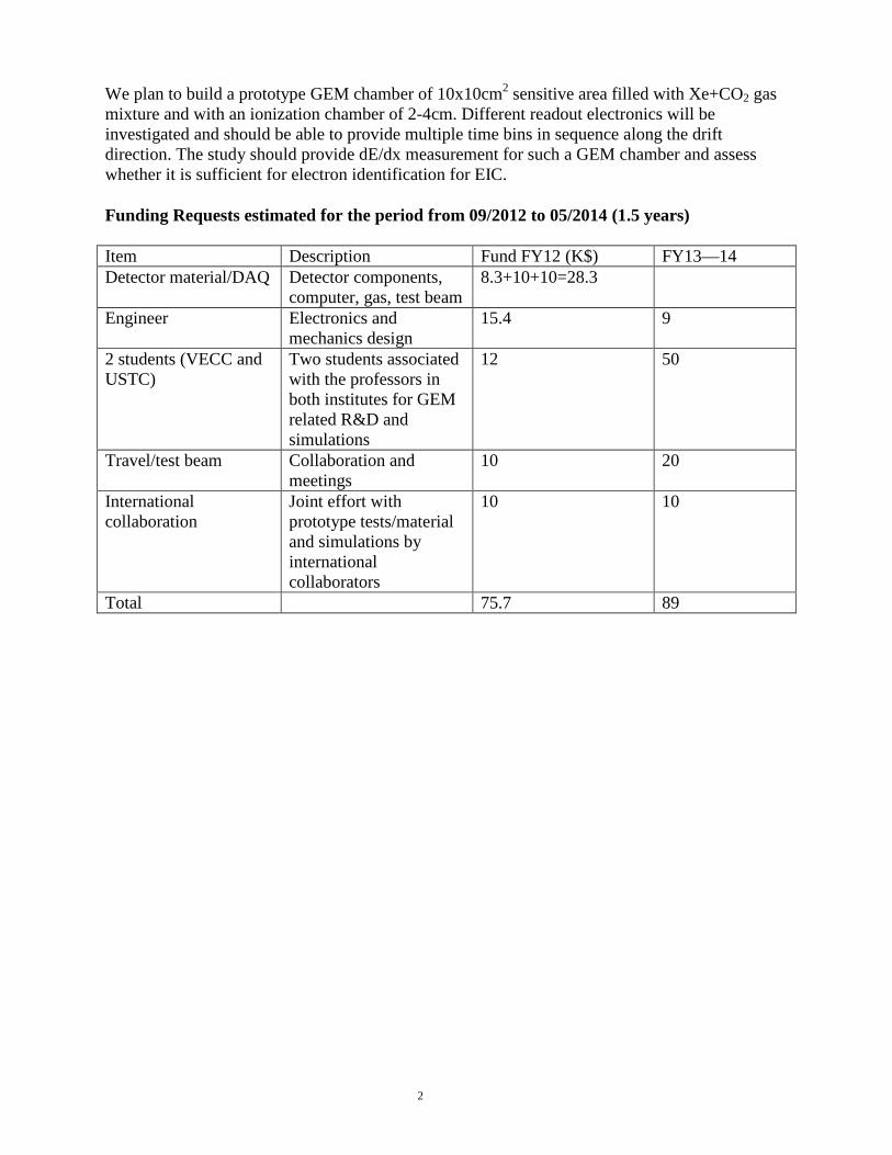
We plan to build a prototype GEM chamber of 10x10cm2 sensitive area filled with Xe+CO2 gas mixture and with an ionization chamber of 2-4cm. Different readout electronics will be investigated and should be able to provide multiple time bins in sequence along the drift direction. The study should provide dE/dx measurement for such a GEM chamber and assess whether it is sufficient for electron identification for EIC.
Funding Requests estimated for the period from 09/2012 to 05/2014 (1.5 years)
Item Description Fund FY12 (K$) FY13—14 Detector material/DAQ Detector components,
computer, gas, test beam 8.3+10+10=28.3
Engineer Electronics and mechanics design
15.4 9
2 students (VECC and USTC)
Two students associated with the professors in both institutes for GEM related R&D and simulations
12 50
Travel/test beam Collaboration and meetings
10 20
International collaboration
Joint effort with prototype tests/material and simulations by international collaborators
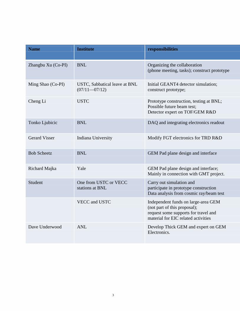
Cheng Li USTC Prototype construction, testing at BNL; Possible future beam test; Detector expert on TOF/GEM R&D
Tonko Ljubicic BNL DAQ and integrating electronics readout
Gerard Visser Indiana University Modify FGT electronics for TRD R&D
Bob Scheetz BNL GEM Pad plane design and interface
Richard Majka Yale GEM Pad plane design and interface; Mainly in connection with GMT project.
Student One from USTC or VECC stations at BNL
Carry out simulation and participate in prototype construction Data analysis from cosmic ray/beam test
VECC and USTC Independent funds on large-area GEM (not part of this proposal); request some supports for travel and material for EIC related activities
Dave Underwood ANL Develop Thick GEM and expert on GEM Electronics.
3
PROPOSAL
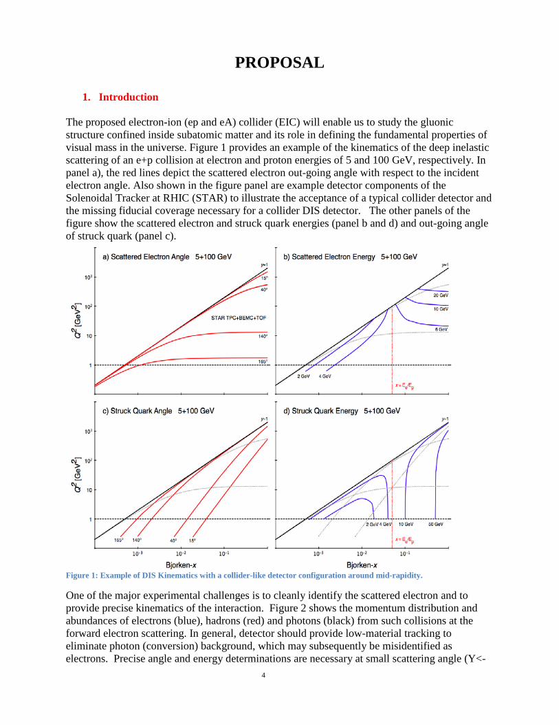
1. Introduction The proposed electron-ion (ep and eA) collider (EIC) will enable us to study the gluonic structure confined inside subatomic matter and its role in defining the fundamental properties of visual mass in the universe. Figure 1 provides an example of the kinematics of the deep inelastic scattering of an e+p collision at electron and proton energies of 5 and 100 GeV, respectively. In panel a), the red lines depict the scattered electron out-going angle with respect to the incident electron angle. Also shown in the figure panel are example detector components of the Solenoidal Tracker at RHIC (STAR) to illustrate the acceptance of a typical collider detector and the missing fiducial coverage necessary for a collider DIS detector. The other panels of the figure show the scattered electron and struck quark energies (panel b and d) and out-going angle of struck quark (panel c).
Figure 1: Example of DIS Kinematics with a collider-like detector configuration around mid-rapidity.
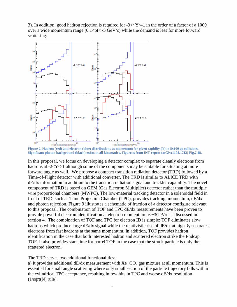
One of the major experimental challenges is to cleanly identify the scattered electron and to provide precise kinematics of the interaction. Figure 2 shows the momentum distribution and abundances of electrons (blue), hadrons (red) and photons (black) from such collisions at the forward electron scattering. In general, detector should provide low-material tracking to eliminate photon (conversion) background, which may subsequently be misidentified as electrons. Precise angle and energy determinations are necessary at small scattering angle (Y<- 4
3). In addition, good hadron rejection is required for -3<~Y<-1 in the order of a factor of a 1000 over a wide momentum range (0.1<pt<~5 GeV/c) while the demand is less for more forward scattering.
Figure 2, Hadron (red) and electron (blue) distributions vs momentum for given rapidity (Y) in 5x100 ep collisions. Significant photon background (black) exists in all kinematics. Figure is from INT report (arXiv:1108.1713) Fig.7.18.
In this proposal, we focus on developing a detector complex to separate cleanly electrons from hadrons at -2<Y<-1 although some of the components may be suitable for situating at more forward angle as well. We propose a compact transition radiation detector (TRD) followed by a Time-of-Flight detector with additional converter. The TRD is similar to ALICE TRD with dE/dx information in addition to the transition radiation signal and tracklet capability. The novel component of TRD is based on GEM (Gas Electron Multiplier) detector rather than the multiple wire proportional chambers (MWPC). The low-material tracking detector in a solenoidal field in front of TRD, such as Time Projection Chamber (TPC), provides tracking, momentum, dE/dx and photon rejection. Figure 3 illustrates a schematic of fraction of a detector configure relevant to this proposal. The combination of TOF and TPC dE/dx measurements have been proven to provide powerful electron identification at electron momentum p<~3GeV/c as discussed in section 4. The combination of TOF and TPC for electron ID is simple: TOF eliminates slow hadrons which produce large dE/dx signal while the relativistic rise of dE/dx at high βγ separates electrons from fast hadrons at the same momentum. In addition, TOF provides hadron identification in the case that both interested hadron and scattered electron strike the Endcap TOF. It also provides start-time for barrel TOF in the case that the struck particle is only the scattered electron. The TRD serves two additional functionalities: a) It provides additional dE/dx measurement with Xe+CO2 gas mixture at all momentum. This is essential for small angle scattering where only small section of the particle trajectory falls within the cylindrical TPC acceptance, resulting in few hits in TPC and worse dE/dx resolution (1/sqrt(N) rule). 5
b) It adds necessary TR signal to the electrons for high momentum (p>2 GeV/c). The transition radiation happens at around gamma>1000 with the current radiator material (ALICE). From practical stand point, only electrons provide such radiation into the ionization chamber in the TRD boosting the effective electron dE/dx to even higher value from the existing relativistic rise. Given the possible space constraint and limited resolution at low momentum, an electromagnetic calorimeter behind a TOF wall may be more suitable for η<-2 in a detector configuration as illustrated in Fig.3. An alternative of increasing electron purity is to add a converter (~4X0) and scintillator behind the TOF for generating and detecting E&M showers from electrons. This converter method also provides a cost-effect approach for detecting/rejecting the large photon background in e+p and e+A collisions (shown in Fig.2). We have preliminary simulation shows that the combination of TRD+TOF+converter can provide electron ID necessary for EIC.
Figure 3: Schematics of a detector with Solenoidal field at mid-rapidity. The proposed
TRD+TOF is placed between pole-tip and a low-material tracking gas detector. 2. Transition Radiation detector (TRD) Simulation
Transition radiation occurs when particle traverses material boundary with different dielectric constants. The radiation depends on gamma factor and usually is effective at gamma~>2000. Figure 4 (left panel) shows a schematic of ALICE TRD. The ALICE TRD is a stack of 6 such components along the radial direction outside of the barrel TPC. The radiator consists of polypropylene fiber mats of 3.2cm in-between two Rohacell forms (0.8cm each) and is reinforced with carbon-fiber sheets (0.1mm thick) laminated onto the outer surface. The fiducial drift chamber is 3cm long filled with Xe+CO2 (85/15) gas mixing. The signals are
TPC
IP
Inner Tracking
Iron Endcap
TRD
TOF / Absorber
6
readout by multiple-wire proportional chamber (MWPC). Right panel of Fig.4 shows the performance of this detector in pp collisions at 7 TeV center-of-mass energy for electron and pion momentum at 2 GeV/c. Our proposal is to replace the WMPC readout with GEM detectors, which provides higher rate capability and is more radiation hard. This may be crucial for electron and hadron detection at high eta. As a start of the simulation for this project, we use detector with 3 layers, which is possible to fit inside conventional detector configuration, such as the familiar STAR pole-tip behind TPC readout wire chambers. Figure 5 shows a stand-alone TRD+TOF+converter simulation in GEANT4. An electron with momentum p=3 GeV (red line) incident to the detector from right, producing TR signals and ionization in the 3 TRD drift chambers. These signals are readout by triple GEM detectors with hit position and dE/dx information. The electron also provides signal in the MRPC TOF and creates an E&M shower through the converter behind the TOF. The shower deposits signals in the coarsely granulated scintillators behind the convertors. In the near future, the plan is to put such a detector component into a more realistic detector environment with full ep and eA event simulation.
Figure 5: GEANT4 simulation of a 3-GeV electron (red) incident on the TRD+TOF configuration. E&M shower is created at the converter (4X0).
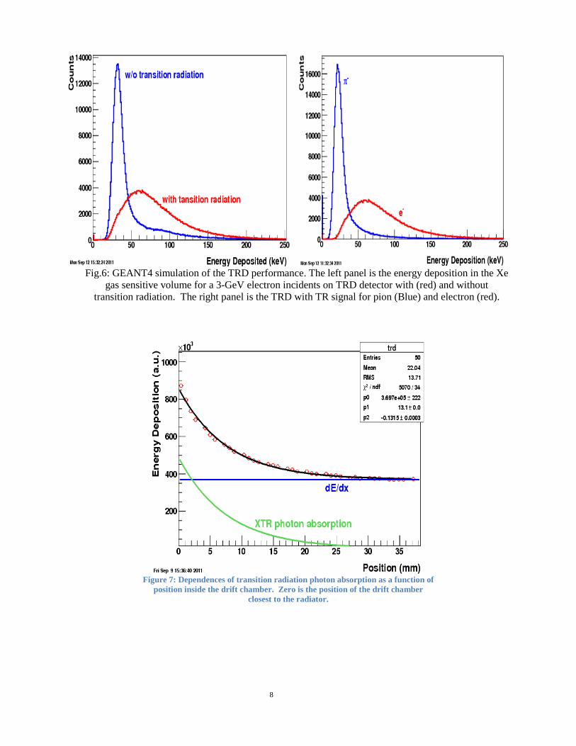
Figure 6 left panel shows the signals from TRD (energy deposition) with (red) and without (blue) transition radiation signals for the same electrons. Right panel shows the signals for pions (blue) and electrons (red) from full-functioning TRD with active transition radiation.
7
Fig.6: GEANT4 simulation of the TRD performance. The left panel is the energy deposition in the Xe
gas sensitive volume for a 3-GeV electron incidents on TRD detector with (red) and without transition radiation. The right panel is the TRD with TR signal for pion (Blue) and electron (red).
Figure 7: Dependences of transition radiation photon absorption as a function of
position inside the drift chamber. Zero is the position of the drift chamber closest to the radiator.
8
Figure 8: electron efficiency vs hadron rejection for TRD in different electron incident energies. At electron efficiency
about 85%, the hadron rejection is about 50.
3. Performance and Experience of Detector R&D
Collaborators within this group have experiences in R&D and construction of GEM and MRPC TOF detectors. The barrel MRPC TOF project, which is a joint effort of USA-China collaboration, has been successfully carried out from the R&D phase and subsequently to the successful completion of the project in 2009. An R&D project on “novel and compact muon detector” was proposed by us in 2007 and led to the STAR Muon Telescope Detector (MTD), which is designed to cover the barrel for muon identification based on long-strip MRPC modules. The MTD project has been approved and the construction is underway. Our collaboration also has been active in GEM R&D and detector projects. Two trackers based on triple-GEM detectors have been in construction phase in STAR. One is the Forward GEM Tracker (FGT), which is designed to track and distinguish the electron charge sign from W+- decays in the forward 1<η<2. A few small GEM modules have been proposed to be installed around TPC for monitoring the TPC performance and space charge distortion. This project is expected to complete for this coming run 12. The proposals of these detectors can be found at: http://drupal.star.bnl.gov/STAR/future/proposals
9
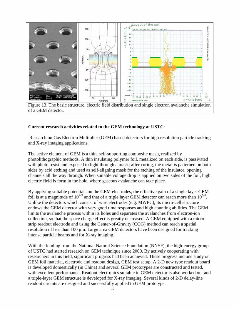
Figure 13. The basic structure, electric field distribution and single electron avalanche simulation of a GEM detector. Current research activities related to the GEM technology at USTC: Research on Gas Electron Multiplier (GEM) based detectors for high resolution particle tracking and X-ray imaging applications. The active element of GEM is a thin, self-supporting composite mesh, realized by photolithographic methods. A thin insulating polymer foil, metalized on each side, is passivated with photo resist and exposed to light through a mask; after curing, the metal is patterned on both sides by acid etching and used as self-aligning mask for the etching of the insulator, opening channels all the way through. When suitable voltage drop is applied on two sides of the foil, high electric field is form in the hole, where gaseous avalanche can take place. By applying suitable potentials on the GEM electrodes, the effective gain of a single layer GEM foil is at a magnitude of 102-3 and that of a triple layer GEM detector can reach more than 105-6. Unlike the detectors which consist of wire electrodes (e.g. MWPC), its micro-cell structure endows the GEM detector with very good time responses and high counting abilities. The GEM limits the avalanche process within its holes and separates the avalanches from electron-ion collection, so that the space charge effect is greatly decreased. A GEM equipped with a micro-strip readout electrode and using the Center-of-Gravity (COG) method can reach a spatial resolution of less than 100 μm. Large area GEM detectors have been designed for tracking intense particle beams and for X-ray imaging. With the funding from the National Natural Science Foundation (NNSF), the high-energy group of USTC had started research on GEM technique since 2000. By actively cooperating with researchers in this field, significant progress had been achieved. These progress include study on GEM foil material, electrode and readout design, GEM test setup. A 2-D new type readout board is developed domestically (in China) and several GEM prototypes are constructed and tested, with excellent performance. Readout electronics suitable to GEM detector is also worked out and a triple-layer GEM structure is developed for X-ray imaging. Several kinds of 2-D delay-line readout circuits are designed and successfully applied to GEM prototype. 10
Figure 14. (left) A delay-line readout circuit board and (right) a triple layer GEM prototype equipped with such readout.
Figure 15. R-ray imaging system with GEM technique.
Activities at BNL and other collaboration institutes in USA In 2007, we have a test beam experiment at FermiLab meson beam line for the joint R&D projects of MTD and FGT (T963). Technical papers of the test beam results have been published in NIMA 593 (2009) 307 for MTD MRPC and NIMA 598 (2009) 432 for FGT GEM. Fig.16 shows the T963 setup at Fermilab in 2007 with MRPC and GEM test stands together with other detectors (TOF, MWPC stations and Cherenkov counters). Fig.17 shows the correlations between the position calculated from MRPC long-strip and hits from GEM. Fig.18 shows the GEM performance on position resolution and ionization signal.
11
Figure 16: Setup of MRPC and GEM test stand at FermiLab test beam (T963).
Figure 17: Long strip MRPC position resolution vs GEM position in the test beam.
Figure 18: Performance of GEM prototype: position resolution (left panel) and dE/dx distribution in the test beam.
12
Figure 19: readout design for GMT and same design will be used for TRD prototype.
Figure 19 is the readout pad drawing to be used in a monitoring detector for TPC alignment and distortion correction. Eight modules will be installed in STAR at different azimuthal and eta locations replacing some of the TOF MRPC modules in the coming FY12. We intend to use this design for our TRD prototype. Section 5 provides the details of the electronic readout and DAQ. Prototype assembly and cosmic ray tests will be done at BNL. The same lab space has been used in the past for prototype MTD tests and assembling the GMT into TOF trays. Activities on Large-area GEM at VECC for CBM As a part of the development effort for building a muon detection system in the CBM experiment in the upcoming FAIR facility at GSI-Germany, VECC group is involved in R&D work on GEM as tracking chambers. In CBM muon chambers, where tracking will be done inside absorbers, the chambers should cover an area of 20m2 working at a rate upto 16 MHz/cm2. Main goal of this R&D is therefore to develop highly efficient large-size GEM modules to be readout by self-triggered readout system with highly granular pad readout. At VECC so far, several triple GEM modules each of 10cm x 10cm dimensions have been made and tested using radioactive source (Ru-90 and Fe-55), proton beam and cosmic rays. A self-triggered ASIC called n-XYTER has been used for the readout. The ASIC has a fast channel of 20-nsec trigger time for time-stamp determination and a slow channel for charge measurement. All the foils were obtained from CERN fabricated by both types of technology e.g. conventional single-mask and recently developed single-mask. Pad-planes used were of various types, e.g. staggered rectangular pads of 1.8mm x 16 mm, regular square pads of 3mm x 3mm and 4mm x 4mm. In test beams, well-defined MIP-like ADC spectra and efficiency >95% were obtained. The cluster-size is mostly contained in a single 3mmx3mm pad. Well-defined characteristic ADC spectra were obtained from Fe-55 X-source. Recently GEM-chambers have been tested at CERN with secondaries produced by proton beams hitting a 10-cm iron converter. We are in the process of building 30x30cm2 GEMs to be tested with proton beam in January-2012. Arrangements are being made to procure and build large (1m x 0.5m) sector-shaped GEMs with radially increasing pads.
13
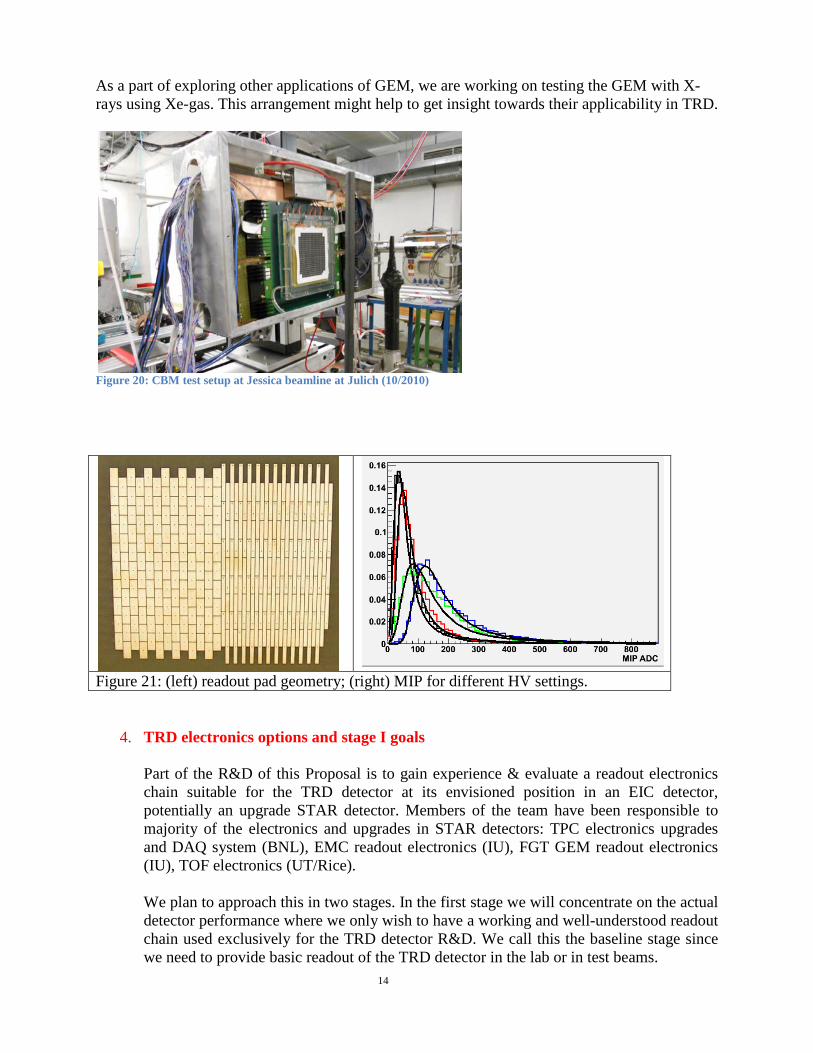
As a part of exploring other applications of GEM, we are working on testing the GEM with X-rays using Xe-gas. This arrangement might help to get insight towards their applicability in TRD.
Figure 20: CBM test setup at Jessica beamline at Julich (10/2010)
Figure 21: (left) readout pad geometry; (right) MIP for different HV settings.
4. TRD electronics options and stage I goals Part of the R&D of this Proposal is to gain experience & evaluate a readout electronics chain suitable for the TRD detector at its envisioned position in an EIC detector, potentially an upgrade STAR detector. Members of the team have been responsible to majority of the electronics and upgrades in STAR detectors: TPC electronics upgrades and DAQ system (BNL), EMC readout electronics (IU), FGT GEM readout electronics (IU), TOF electronics (UT/Rice). We plan to approach this in two stages. In the first stage we will concentrate on the actual detector performance where we only wish to have a working and well-understood readout chain used exclusively for the TRD detector R&D. We call this the baseline stage since we need to provide basic readout of the TRD detector in the lab or in test beams.
14
In the second stage we would like to concentrate on the evaluation or initial development of the frontend electronics which could be suitable for a production version of the TRD detector. We expect to complete Stage I during the first 3-6 months of the Project while the remaining time would be entirely spent on Stage II. Stage I -- Baseline Electronics
For the baseline stage we plan to use the currently existing electronics readout used for the “Forward Gem Tracker” (FGT) at STAR with modifications already made for the “GEM Monitor for the TPC” (GMT) detector also at STAR. This electronics system was designed for FGT’s and GMT’s GEM chambers and is based upon the APV frontend ASIC, custom STAR-specific electronics and the STAR-standard DDL optical link. Such a system is already in use for the QA phase of the FGT detector and will be used in the physics production during the RHIC FY12 run. Apart from installing the electronics on the prototype detector the 2 necessary modifications and thus milestones of Stage I would be: Milestone 1: Modifications of the FGT/GMT readout system to enable at least 100 time samples readout. Milestone 2: Modifications necessary to enable operation at collision frequencies of up to 15 MHz, as required by eRHIC. The cost estimate of Stage I of the TRD frontend electronics is in Table 1.
ARM board 2700 $
ARC board 1000 $
backplane & cardcage 1000 $
interface cards 1000 $
SIU optical interface card 700 $
engineering (1 man-month) 15000 $
TOTAL 21400 $ Table 1: Cost of the baseline electronics system Stage II — Evaluation of TRD Electronics Options
15
During the first part of Stage II we plan to provide a list of precise requirements for an electronics readout system necessary for a physics production detector. Although some of the requirements are already known and understood we assume that more precise or more stringent requirements will follow from the first initial test of the prototype, as we gain more experience from our R&D. We plan to propose the Stage II R&D next year. The currently known requirements for final electronics are:
1. Synchronous time sampling suitable for a drift TRD with good energy resolution. 2. Low mass. 3. Efficient cooling. 4. Some level of radiation tolerance. 5. Magnetic field tolerance.
Requirement 1 -- time sampling with good energy resolution The ETTIE TRD detector is also a small TPC so the readout electronics needs to sample the detector GEM signal at fixed times synchronous to the collision clock. An example of an existing ASIC which was designed for TPCs is the ALTRO chip already used in the STAR TPC. The electronics also need to provide good noise and energy resolution characteristics for the dE/dx measurement. Requirement 2 -- low mass The ETTIE detector is situated in the forward direction and aims to detect electrons. As such the mass of the electronics system through which the electrons pass needs to be as small as possible. The designs we plan to evaluate will thus attempt to split the electronics chain into a preamplification and shaping analog stage which we presume will be located next to the detector but will be as low mass as possible, and the digitization and signal processing stage(s) which we assume will be outside the critical volume. Requirement 3 -- power consumption The proposed ETTIE detector is fully enclosed within the STAR magnet volume and thus the electronics need to be either sufficiently low power or the cooling system needs to be efficient and low in mass. Requirement 4 -- radiation tolerance Since at least part of the frontend electronics will be showered by particles produced from eRHIC collisions and other collision debris we need to evaluate the level of radiation and thus the necessary electronics radiation tolerance of our system. This will provide guidelines to the final design and might provide constraints to the available technologies used (i.e. FPGAs or other CPLDs). Requirement 5 -- magnetic field tolerance
16
Some part of the electronics will be situated within the STAR magnet and as such need to work reliably in a 0.5T magnetic field. Although we do not feel that this would cause any problems we need to bear in mind this requirement. During the Stage II of the TRD readout electronics R&D we plan to first evaluate existing ASICs suitable for the TRD detector as well as investigate and potentially partake in new developments throughout the physics experiments in nuclear and high-energy community such as the RD51 collaboration at CERN.
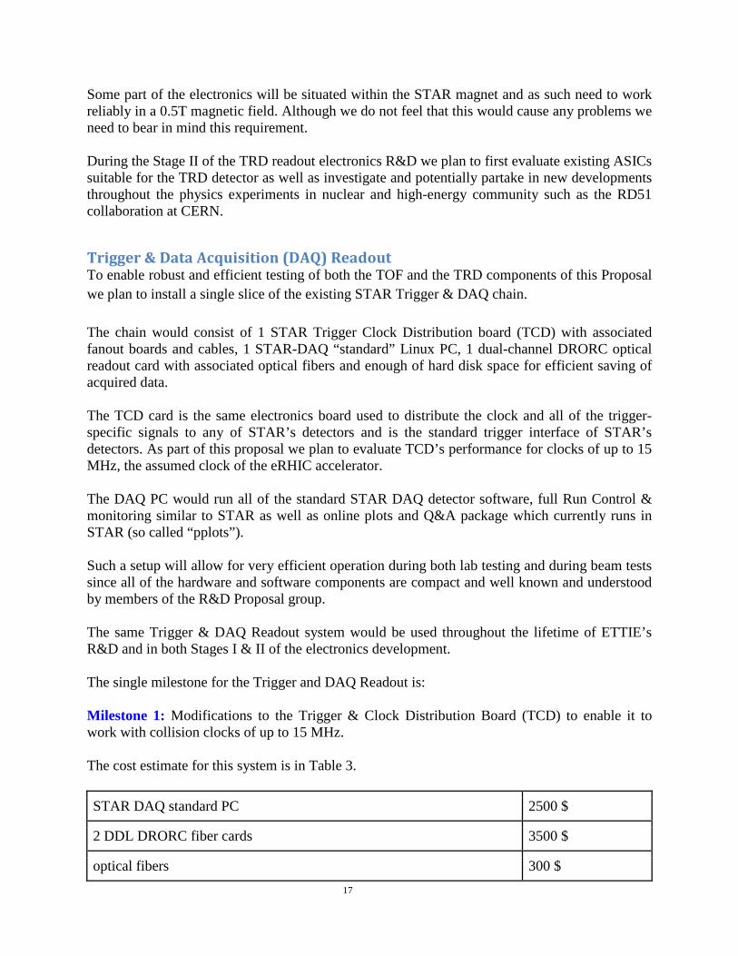
Trigger & Data Acquisition (DAQ) Readout To enable robust and efficient testing of both the TOF and the TRD components of this Proposal we plan to install a single slice of the existing STAR Trigger & DAQ chain. The chain would consist of 1 STAR Trigger Clock Distribution board (TCD) with associated fanout boards and cables, 1 STAR-DAQ “standard” Linux PC, 1 dual-channel DRORC optical readout card with associated optical fibers and enough of hard disk space for efficient saving of acquired data. The TCD card is the same electronics board used to distribute the clock and all of the trigger-specific signals to any of STAR’s detectors and is the standard trigger interface of STAR’s detectors. As part of this proposal we plan to evaluate TCD’s performance for clocks of up to 15 MHz, the assumed clock of the eRHIC accelerator. The DAQ PC would run all of the standard STAR DAQ detector software, full Run Control & monitoring similar to STAR as well as online plots and Q&A package which currently runs in STAR (so called “pplots”). Such a setup will allow for very efficient operation during both lab testing and during beam tests since all of the hardware and software components are compact and well known and understood by members of the R&D Proposal group. The same Trigger & DAQ Readout system would be used throughout the lifetime of ETTIE’s R&D and in both Stages I & II of the electronics development. The single milestone for the Trigger and DAQ Readout is: Milestone 1: Modifications to the Trigger & Clock Distribution Board (TCD) to enable it to work with collision clocks of up to 15 MHz. The cost estimate for this system is in Table 3.
STAR DAQ standard PC 2500 $
2 DDL DRORC fiber cards 3500 $
optical fibers 300 $ 17
network equipment (switches, cables) 500 $
TCD board, chassis and power supply 1500 $
TOTAL 8300 $ Table 3: Cost of the DAQ Readout System
18
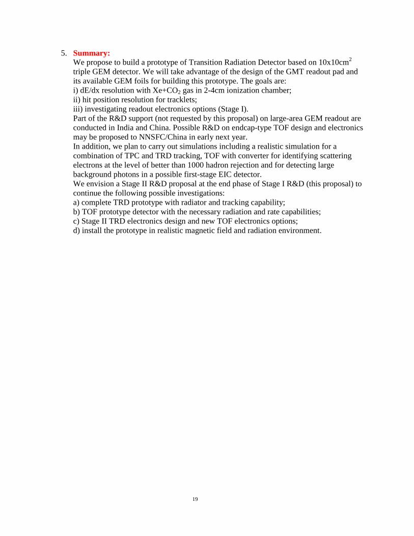
5. Summary:
We propose to build a prototype of Transition Radiation Detector based on 10x10cm2 triple GEM detector. We will take advantage of the design of the GMT readout pad and its available GEM foils for building this prototype. The goals are: i) dE/dx resolution with Xe+CO2 gas in 2-4cm ionization chamber; ii) hit position resolution for tracklets; iii) investigating readout electronics options (Stage I). Part of the R&D support (not requested by this proposal) on large-area GEM readout are conducted in India and China. Possible R&D on endcap-type TOF design and electronics may be proposed to NNSFC/China in early next year. In addition, we plan to carry out simulations including a realistic simulation for a combination of TPC and TRD tracking, TOF with converter for identifying scattering electrons at the level of better than 1000 hadron rejection and for detecting large background photons in a possible first-stage EIC detector. We envision a Stage II R&D proposal at the end phase of Stage I R&D (this proposal) to continue the following possible investigations: a) complete TRD prototype with radiator and tracking capability; b) TOF prototype detector with the necessary radiation and rate capabilities; c) Stage II TRD electronics design and new TOF electronics options; d) install the prototype in realistic magnetic field and radiation environment.
19
Work and Progresses (05/2012—10/2012) In the previous submission, we have shown to the committee what/why a TRD+TOF+TPC can provide excellent electron PID. For this updated version, we would like to focus on just R&D on TRD. The following paragraphs respond to major comments and recommendations from the committee review last December and update the new developments in terms of hardware and simulations. a) The Committee encourages the authors to delineate more thoroughly the requirements on the electronics. Such electronics were developed at BNL for the PHENIX Time Expansion Chamber and include a preamp with wide dynamic range coupled to a planar TPC and a non-linear FADC. The FADC combined a linear lower range with a non-linear upper range to accommodate the 4 large difference in energy deposition in a unit gas volume between normal ionization by a minimum-ionizing charged particle and a TR photon of keV energy. A revised proposal should note improvements required beyond the performance achieved above to meet the needs of an EIC. Tonko Ljubicic (BNL) and Gerard Visser (Indiana) have successfully modified the APV chips to be able to readout multiple time bins and digitized them with 12-bit ADC. This should answer the committee's suggestion about using Flash ADC which is only 5 bits. Currently, STAR has used similar system for Forward GEM Tracker (FGT) (http://drupal.star.bnl.gov/STAR/system/files/fgt_review_0.pdf ) GEM Monitoring of TPC Tracking Calibration (GMT) http://drupal.star.bnl.gov/STAR/system/files/Proposal-to-Install-GEM-Chambers-GMT.pdf Intermediate Silicon Tracker Test Stand (IST) (http://drupal.star.bnl.gov/STAR/system/files/HFT_Report_Final.pdf )
Figure 22: Multiple Time bins (18) readout from APV chip for a test signal input. The signal (decrease as a function of time) is in-between the digital header.
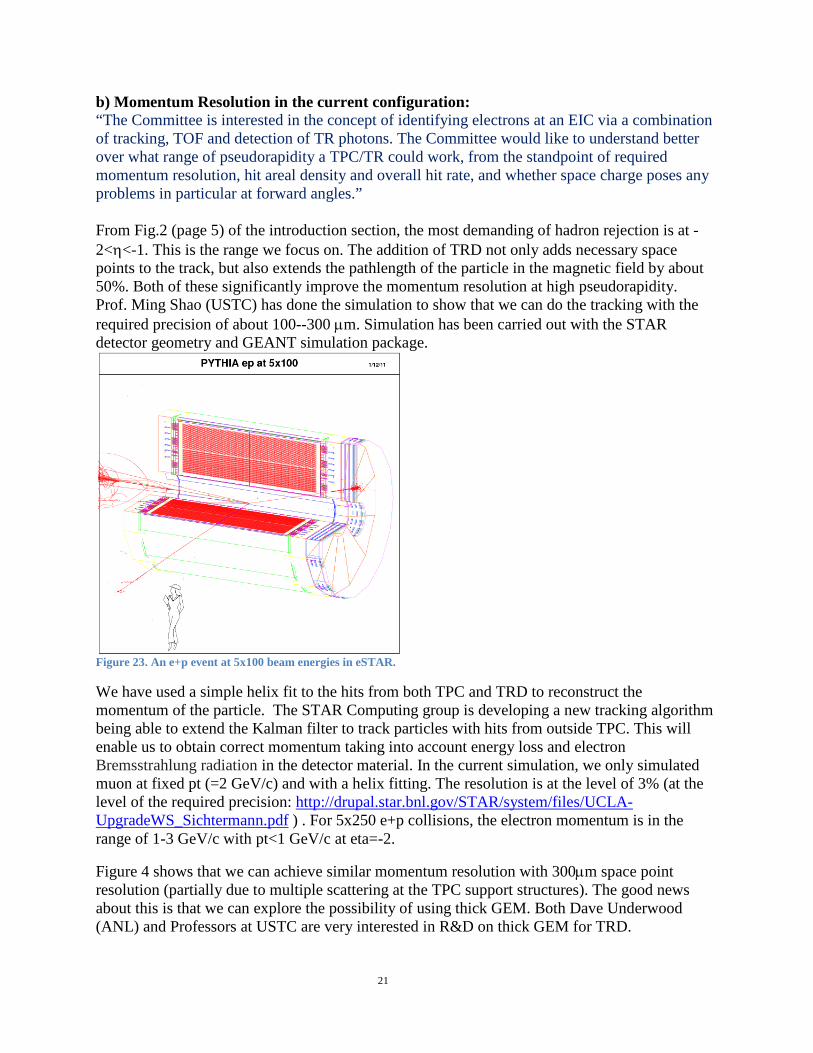
b) Momentum Resolution in the current configuration: “The Committee is interested in the concept of identifying electrons at an EIC via a combination of tracking, TOF and detection of TR photons. The Committee would like to understand better over what range of pseudorapidity a TPC/TR could work, from the standpoint of required momentum resolution, hit areal density and overall hit rate, and whether space charge poses any problems in particular at forward angles.” From Fig.2 (page 5) of the introduction section, the most demanding of hadron rejection is at -2<η<-1. This is the range we focus on. The addition of TRD not only adds necessary space points to the track, but also extends the pathlength of the particle in the magnetic field by about 50%. Both of these significantly improve the momentum resolution at high pseudorapidity. Prof. Ming Shao (USTC) has done the simulation to show that we can do the tracking with the required precision of about 100--300 µm. Simulation has been carried out with the STAR detector geometry and GEANT simulation package.
Figure 23. An e+p event at 5x100 beam energies in eSTAR. We have used a simple helix fit to the hits from both TPC and TRD to reconstruct the momentum of the particle. The STAR Computing group is developing a new tracking algorithm being able to extend the Kalman filter to track particles with hits from outside TPC. This will enable us to obtain correct momentum taking into account energy loss and electron Bremsstrahlung radiation in the detector material. In the current simulation, we only simulated muon at fixed pt (=2 GeV/c) and with a helix fitting. The resolution is at the level of 3% (at the level of the required precision: http://drupal.star.bnl.gov/STAR/system/files/UCLA-UpgradeWS_Sichtermann.pdf ) . For 5x250 e+p collisions, the electron momentum is in the range of 1-3 GeV/c with pt<1 GeV/c at eta=-2.
Figure 4 shows that we can achieve similar momentum resolution with 300µm space point resolution (partially due to multiple scattering at the TPC support structures). The good news about this is that we can explore the possibility of using thick GEM. Both Dave Underwood (ANL) and Professors at USTC are very interested in R&D on thick GEM for TRD.
Figure 24. Momentum resolution [δ(1/pT)/(1/pT)] as a function of eta for helix fit to the space points in TPC and TRD for pT=2 GeV/c particles.
d) Hit density and space charge estimate: “The Committee is interested in the concept of identifying electrons at an EIC via a combination of tracking, TOF and detection of TR photons. The Committee would like to understand better over what range of pseudorapidity a TPC/TR could work, from the standpoint of required momentum resolution, hit areal density and overall hit rate, and whether space charge poses any problems in particular at forward angles.” The multiplicity distribution from an e+p event is shown in the following figure.
Figure 23: multiplicity distribution in e+p collisions within the current STAR detector setup in our simulation with all detector material taken into account. The cutoff between eta of [-2,4] is due to the acceptance of current detector configuration in the GEANT simulation.
22
This simulation shows that the particle multiplicity density and interaction rate of proposed e+p collisions is very similar to those in p+p collisions at sqrt(s)=200 GeV at RHIC. Table I also shows the particle density per second as seen in TPC in MHz. The results show that the density in e+p is a factor of 8 lower than that in Au+Au collisions at RHIC. It is about an order of magnitude (x25) lower hit density in TPC than that in p+p collisions at sqrt(s)=500 GeV at RHIC. The electron drift velocity in STAR TPC is about 5cm/µs and it takes about 40µs to complete the drift from central membrane to the MWPC sector readout. The TRD drift time is about 2µs and is an order of magnitude shorter than the TPC. The TRD should not have any issue with the pile-up and space charge. Beam species
Sqrt(s) Peak Luminosity (cm^-2)
Cross section (cm^2)
Nch/dη Track density (dNch/dη MHz)
Hit density impact hit finding
Space charge impact tracking
e+p 5x250 1034 10-28 0.7 0.7
Au+Au 100x100 5x1027 7x10-24 161 6 Minor Corrected to good precision
p+p 100x100 5x1031 3x10-26 2 3 Minor Corrected to good precision
p+p 250x250 1.5x1032 4x10-26 3 18 Significant for inner
Corrected to acceptable
Table 4: Particle density in TPC acceptance for different beam conditions. The achieved luminosities are based on RHIC runs upto run11 and estimated TPC performance.
Figure 24: W-boson candidates from p+p collisions at 500 GeV. The x-axis is momentum and charge sign measurements from TPC while the y-axis shows the energy measurement from EMC. Results and details have been published in Phys. Rev. Lett. 106 (2011) 62002, and PRD (arXiv:1112.2980).
23
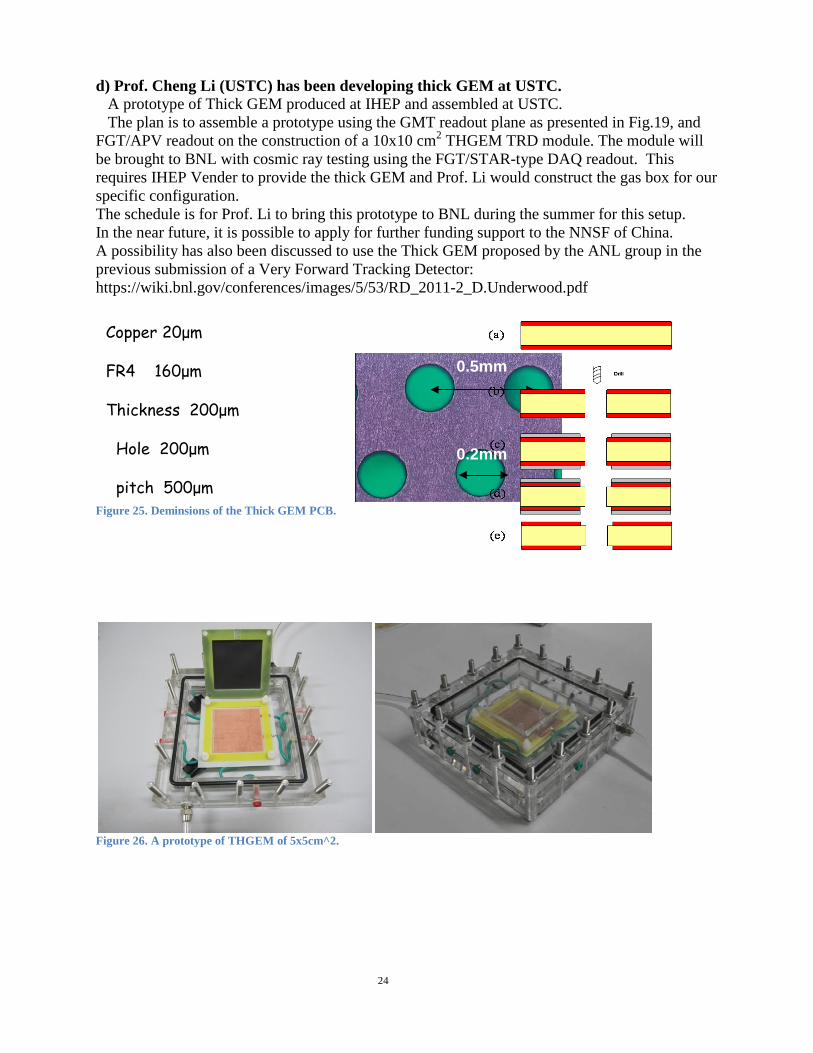
d) Prof. Cheng Li (USTC) has been developing thick GEM at USTC. A prototype of Thick GEM produced at IHEP and assembled at USTC. The plan is to assemble a prototype using the GMT readout plane as presented in Fig.19, and FGT/APV readout on the construction of a 10x10 cm2 THGEM TRD module. The module will be brought to BNL with cosmic ray testing using the FGT/STAR-type DAQ readout. This requires IHEP Vender to provide the thick GEM and Prof. Li would construct the gas box for our specific configuration. The schedule is for Prof. Li to bring this prototype to BNL during the summer for this setup. In the near future, it is possible to apply for further funding support to the NNSF of China. A possibility has also been discussed to use the Thick GEM proposed by the ANL group in the previous submission of a Very Forward Tracking Detector: https://wiki.bnl.gov/conferences/images/5/53/RD_2011-2_D.Underwood.pdf
The proposed electron-ion (ep and eA) collider (EIC) will enable us to study the gluonic structure confined inside subatomic matter and its role in defining the fundamental properties of visual mass in the universe. However, one of the major experimental challenges is to cleanly identify the scattered electron and to provide precise kinematics of the interaction. We propose a compact transition radiation detector (TRD) followed by a Time-of-Flight detector with additional converter(Fig. 1). The TRD is similar to ALICE TRD with dE/dx information in addition to the transition radiation signal and tracklet capability. The novel component of TRD is based on GEM (Gas Electron Multiplier) detector rather than the multiple wire proportional chambers (MWPC), because GEM has excellent spatial resolution and high detection efficiency. The TRD serves two functionalities:1) It provides additional dE/dx measurement with Xe+CO2 gas mixture at all momentum. This is essential for small angle scattering where only small section of the particle trajectory falls within the cylindrical TPC acceptance, resulting in few hits in TPC and worse dE/dx resolution (1/sqrt(N) rule). 2) It adds necessary TR signal to the electrons for high momentum (p>2 GeV/c). The transition radiation happens at around gamma>1000 with the radiator material. From practical stand point, only electrons provide such radiation into the ionization chamber in the TRD boosting the effective electron dE/dx to even higher value from the existing relativistic rise. In this paper, we focus on TGEM's performance, for example, detection efficiency, spatial resolution, track reconstruction capability, etc. 2. TGEM structure and Cosmic ray test system setup
The TGEM in this test use a new type foil obtained via global etching processes. TGEM's holes' parameters are as follow: hole diameter is 0.2mm hole pitch is 0.5mm. The rim, clearance region around the hole is from 5 to 10 μm. The TGEM and regular GEM have the same effective readout area(10×10 cm2) and readout style. The x direction readout pitch of GEM and TGEM is strip-style while the y direction is pad-style, the pitch width is 800μm(Fig. 2). There are two different ionization gap width for TGEM, 3.8mm and 11.3mm,respectively, and the GEM's ionization gap width is 3.8mm. The GEM(TGEM) is placed in a gas-tight aluminum box, which is supplied with a standard atmosphere gas mixture. The component of the gas is 90% Ar + 10% CO2.
Fig. 1 Schematics of a detector with Solenoidal field at mid-rapidity. The proposed TRD+TOF is placed
between pole-tip and a low-material tracking gas detector.
Fig. 2 The picture of Thick GEM foil
25
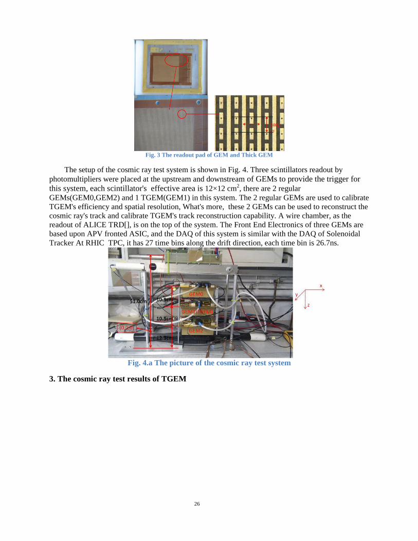
Fig. 3 The readout pad of GEM and Thick GEM
The setup of the cosmic ray test system is shown in Fig. 4. Three scintillators readout by photomultipliers were placed at the upstream and downstream of GEMs to provide the trigger for this system, each scintillator's effective area is 12×12 cm2, there are 2 regular GEMs(GEM0,GEM2) and 1 TGEM(GEM1) in this system. The 2 regular GEMs are used to calibrate TGEM's efficiency and spatial resolution, What's more, these 2 GEMs can be used to reconstruct the cosmic ray's track and calibrate TGEM's track reconstruction capability. A wire chamber, as the readout of ALICE TRD[], is on the top of the system. The Front End Electronics of three GEMs are based upon APV fronted ASIC, and the DAQ of this system is similar with the DAQ of Solenoidal Tracker At RHIC TPC, it has 27 time bins along the drift direction, each time bin is 26.7ns.
Fig. 4.a The picture of the cosmic ray test system
3. The cosmic ray test results of TGEM
26
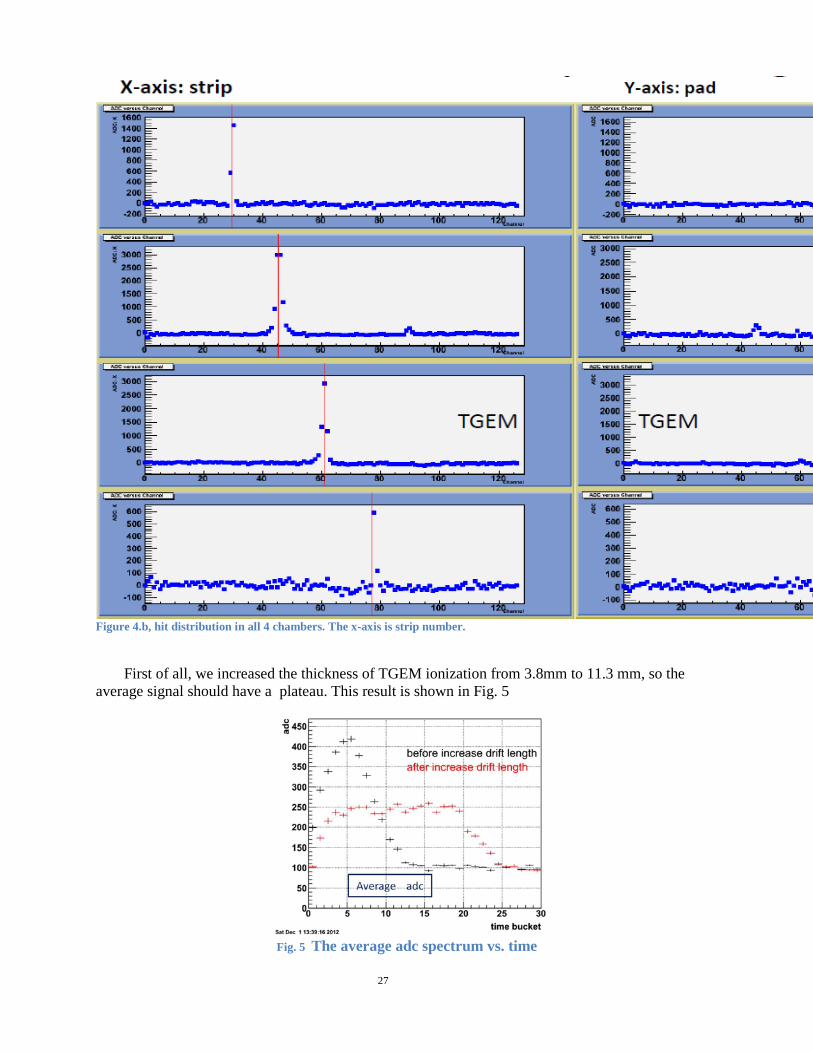
Figure 4.b, hit distribution in all 4 chambers. The x-axis is strip number.
First of all, we increased the thickness of TGEM ionization from 3.8mm to 11.3 mm, so the
average signal should have a plateau. This result is shown in Fig. 5
Fig. 5 The average adc spectrum vs. time
27
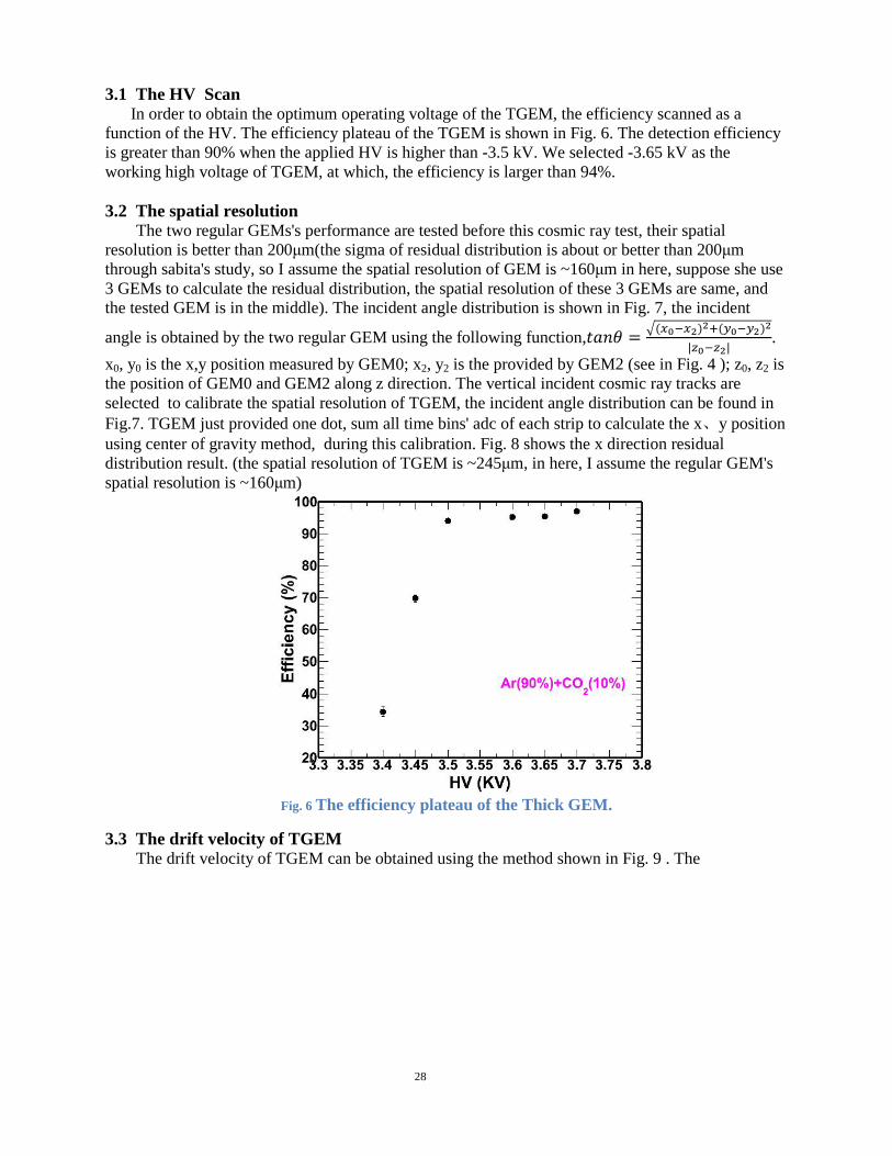
3.1 The HV Scan In order to obtain the optimum operating voltage of the TGEM, the efficiency scanned as a
function of the HV. The efficiency plateau of the TGEM is shown in Fig. 6. The detection efficiency is greater than 90% when the applied HV is higher than -3.5 kV. We selected -3.65 kV as the working high voltage of TGEM, at which, the efficiency is larger than 94%.
3.2 The spatial resolution
The two regular GEMs's performance are tested before this cosmic ray test, their spatial resolution is better than 200μm(the sigma of residual distribution is about or better than 200μm through sabita's study, so I assume the spatial resolution of GEM is ~160μm in here, suppose she use 3 GEMs to calculate the residual distribution, the spatial resolution of these 3 GEMs are same, and the tested GEM is in the middle). The incident angle distribution is shown in Fig. 7, the incident
angle is obtained by the two regular GEM using the following function,𝑡𝑎𝑛𝜃 = �(𝑥0−𝑥2)2+(𝑦0−𝑦2)2
|𝑧0−𝑧2|.
x0, y0 is the x,y position measured by GEM0; x2, y2 is the provided by GEM2 (see in Fig. 4 ); z0, z2 is the position of GEM0 and GEM2 along z direction. The vertical incident cosmic ray tracks are selected to calibrate the spatial resolution of TGEM, the incident angle distribution can be found in Fig.7. TGEM just provided one dot, sum all time bins' adc of each strip to calculate the x、y position using center of gravity method, during this calibration. Fig. 8 shows the x direction residual distribution result. (the spatial resolution of TGEM is ~245μm, in here, I assume the regular GEM's spatial resolution is ~160μm)
Fig. 6 The efficiency plateau of the Thick GEM.
3.3 The drift velocity of TGEM The drift velocity of TGEM can be obtained using the method shown in Fig. 9 . The
28
Fig. 7 The cosmic ray incident angle distribution
Fig. 8 the residual distribution of TGEM's x direction; x_calculate_tgem is the projection position of TGEM using GEM0
& GEM2; x_tgem is the position provided by TGEM using center of gravity method
maximum adc point is selected to calculate this point's z position(z1) using �(𝑥0−𝑥2)2+(𝑦0−𝑦2)2
𝑧0−𝑧2=
�(𝑥0−𝑥1)2+(𝑦0−𝑦1)2
𝑧0−𝑧1, then using the relation of z position vs. drift time to calculate the drift velocity. In
order to obtain a precise z1 value, an offset(4.1cm) is set between each two gems along y direction to make the incident angle lager. Fig. 9(b) shows the result of TGEM's drift velocity which is roughly consistent with the data published by ALICE. The z direction(along drift direction) spatial resolution can be calculated through projecting the correlation of z position vs. drift time shown in Fig. 9(a) along the line shown in Fig. 9(b). The TGEM's z spatial resolution is ~1.0 mm, which is shown in Fig. 9(c)
29
Fig. 9 (a) the correlation of z position vs. drift time; (b) using a linear function to fit the
correlation, the slope is the drift velocity; (c) z direction resolution of TGEM
3.4 Track reconstruction capability of TGEM Fig. 10 illustrates the track reconstruction principle of TGEM. The APV board has 27 time
buckets, trying to search a cluster for each time bucket, if success, calculating the x(y) position using center gravity method. Then fit these points to get the slope of incident track if the number of cluster is more than 3.
Fig. 10 The principle of TGEM's track reconstruction
Using GEM0 and GEM2 to reconstruct the cosmic ray track, the resolution of slope obtained from GEM0 and GEM2 is ~ 8*10-4, so we can using the correlation of tgem_slope(obtained by TGEM) and slope02(obtained by GEM0 and GEM2) to calibrate the TGEM's resolution of slope which indicates the track reconstruction capability. These results are shown in Fig. 11 and Fig12. Fig11(c) and Fig 11(d) illustrate the slope resolution of x direction and y direction of TGEM are 0.030 and 0.032, respectively. The thickness of ionization gap is 11.3mm, so the resolution of slope provided by TGEM is consistent with TGEM’s spatial resolution. The slope resolution of y direction is a little worse than that of x direction, which may be caused by the multi-scattering.
30
Fig. 11 (a) The correlation of x direction's slope obtained by TGEM itself vs. obtained by GEM0 and GEM2 ; (b) slope resolution of TGEM's x direction; (c) slope resolution of TGEM's y direction; (d) TGEM's slope resolution as a function of x(y) dirction's incident angle
3.5 Gain uniformity and stability of TGEM TGEM's readout is divided into 8×8 sub-regions, due to the low statistic of the peripheral sub-
regions, the middle 4×4 sub-regions are used to be done the uniformity calibration. The non-uniformity is described by (adc-adcaverage)/adcaverage . From Fig. 12, the fluctuation of dE/dx is less than 10%.
Fig. 12 (a) average adc value of each sub-region; (b) de/dx fluctuation of each sub-region
31
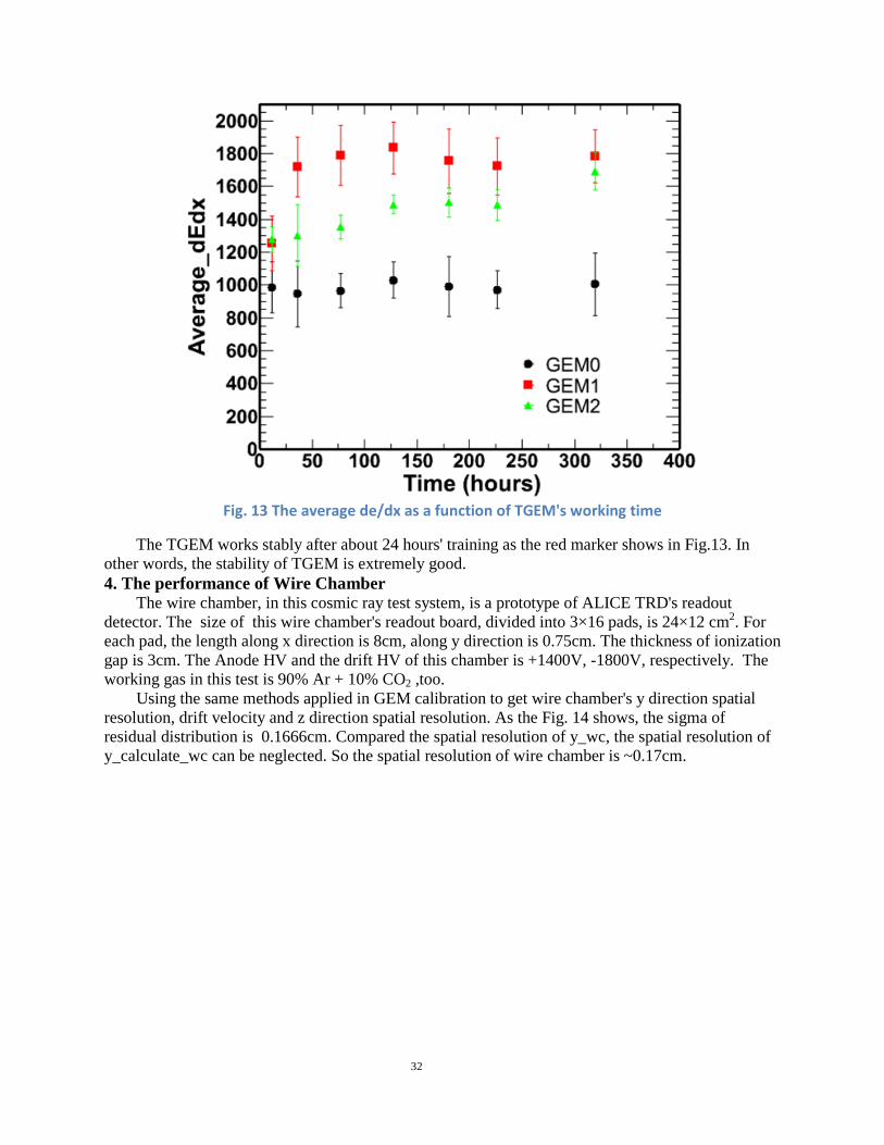
Fig. 13 The average de/dx as a function of TGEM's working time
The TGEM works stably after about 24 hours' training as the red marker shows in Fig.13. In other words, the stability of TGEM is extremely good. 4. The performance of Wire Chamber
The wire chamber, in this cosmic ray test system, is a prototype of ALICE TRD's readout detector. The size of this wire chamber's readout board, divided into 3×16 pads, is 24×12 cm2. For each pad, the length along x direction is 8cm, along y direction is 0.75cm. The thickness of ionization gap is 3cm. The Anode HV and the drift HV of this chamber is +1400V, -1800V, respectively. The working gas in this test is 90% Ar + 10% CO2 ,too.
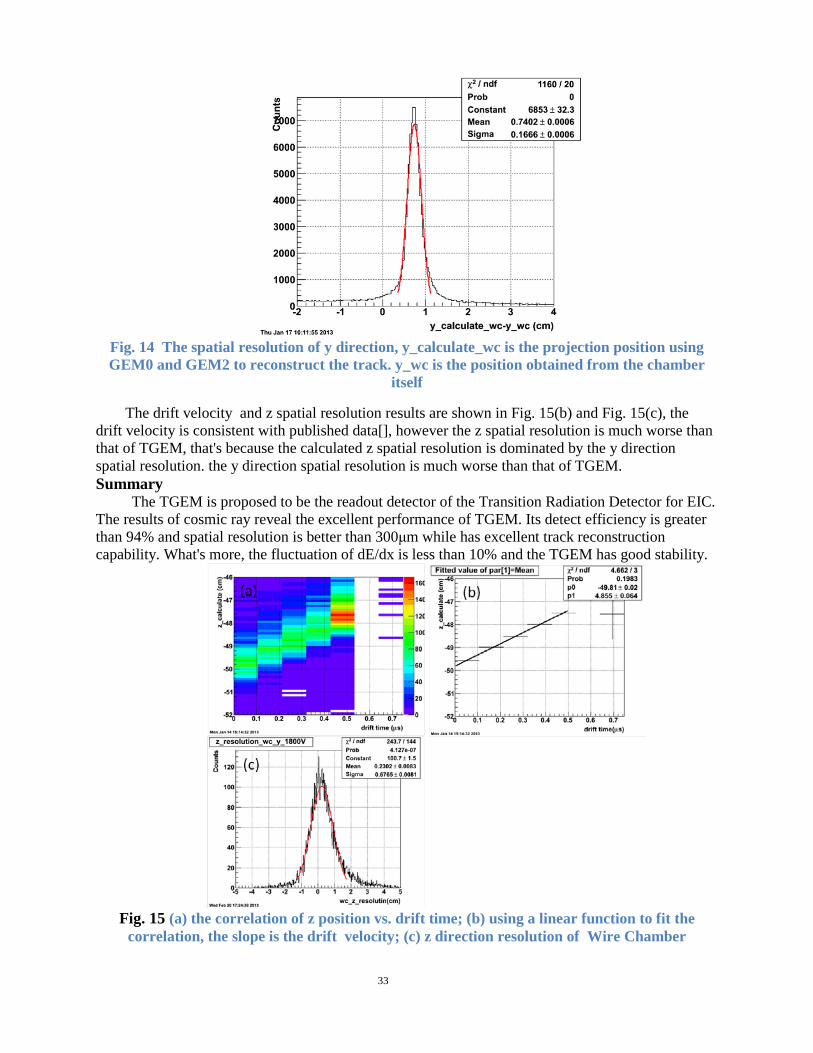
Using the same methods applied in GEM calibration to get wire chamber's y direction spatial resolution, drift velocity and z direction spatial resolution. As the Fig. 14 shows, the sigma of residual distribution is 0.1666cm. Compared the spatial resolution of y_wc, the spatial resolution of y_calculate_wc can be neglected. So the spatial resolution of wire chamber is ~0.17cm.
32
Fig. 14 The spatial resolution of y direction, y_calculate_wc is the projection position using GEM0 and GEM2 to reconstruct the track. y_wc is the position obtained from the chamber
itself
The drift velocity and z spatial resolution results are shown in Fig. 15(b) and Fig. 15(c), the drift velocity is consistent with published data[], however the z spatial resolution is much worse than that of TGEM, that's because the calculated z spatial resolution is dominated by the y direction spatial resolution. the y direction spatial resolution is much worse than that of TGEM. Summary
The TGEM is proposed to be the readout detector of the Transition Radiation Detector for EIC. The results of cosmic ray reveal the excellent performance of TGEM. Its detect efficiency is greater than 94% and spatial resolution is better than 300μm while has excellent track reconstruction capability. What's more, the fluctuation of dE/dx is less than 10% and the TGEM has good stability.
Fig. 15 (a) the correlation of z position vs. drift time; (b) using a linear function to fit the
correlation, the slope is the drift velocity; (c) z direction resolution of Wire Chamber
33
Future Plan (07/2013—03/2014)
1. new design with 3cm drift We are redesigning the gas box so that we can have a fixed drift volume with variable HV setting for drift velocity changes and a window with radiator. Fig.7 shows the schematics of such a design. We have obtained a radiator from ALICE. In addition, STAR has upgraded the APV readout system with a new APV readout Controller (ARC-II). This should provide more flexibility in readout multiple time bins and will be adapted for TRD test stand as well during the summer. We plan to work on this during the summer at the Lab with cosmic ray and prepare for beam test in the fall.
Figure 7, schematic design of a new prototype TRD gas box with 2.5cm drift and radiator.
The design is based on an earlier version of GEM monitor detector for STAR TPC (GMT) by Richard Majka from Yale, shown in Fig.8.
Figure 8, picture of the internal structure of GMT used for cosmic ray test for TRD.
34
Meanwhile, the other PI (Prof. Ming Shao) has setup a test facility at USTC. The plan is to install the readout electronics and eventually test large foils produced by IHEP.
Figure 9, test stand at USTC.
Eight additional thick GEM foils (10x10cm2) have been test and found to meet our requirements. Seven of the eight foils can hold HV upto 1600V while the other one holds upto 1300V. Our working HV is set at nominal value of 800—1000V.
Figure 10, scan pictures of 8 additional foils.
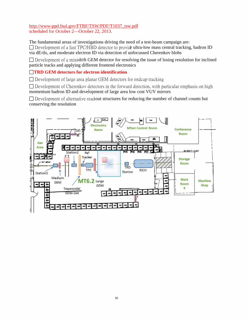
2. Test beam at Fermi Lab Meson Test beam line (experiment T1037) FLYSUB is a consortium consisting of BNL, Florida Tech, Stony Brook University (SBU), University of Virginia (UVa), and Yale University is planning to assemble a set of detectors at FTBF which is targeted toward tracking and PID components of an EIC detector. The groups are working together for about two years and have come up with a common beam-time usage instead of asking for separate test-beam campaigns, with the set-up described in what follows. The ultimate goal of this test-beam effort is to test and verify the performance of the individual components according to their expectation. The detectors are foreseen to share the same beam-line and will be arranged according to their need for particle impact. 35
http://www-ppd.fnal.gov/FTBF/TSW/PDF/T1037_tsw.pdf scheduled for October 2—October 22, 2013. The fundamental areas of investigations driving the need of a test-beam campaign are: Development of a fast TPC/HBD detector to provide ultra-low mass central tracking, hadron ID via dE/dx, and moderate electron ID via detection of unfocussed Cherenkov blobs Development of a mini-drift GEM detector for resolving the issue of losing resolution for inclined particle tracks and applying different frontend electronics TRD GEM detectors for electron identification Development of large area planar GEM detectors for endcap tracking Development of Cherenkov detectors in the forward direction, with particular emphasis on high momentum hadron ID and development of large area low cost VUV mirrors Development of alternative read-out structures for reducing the number of channel counts but conserving the resolution
Work and Progresses (05/2013—12/2013) In the previous submission, we have shown to the committee on R&D on TRD with small module (10x10cm2) in a gas box and cosmic ray test results. In this report, we show the major work done by the STAR Collaboration on physics simulation and Letter of Intent for a possible eSTAR detector. The document is publically available at: https://drupal.star.bnl.gov/STAR/node/28464 Meanwhile, we continue to work toward addressing other issues raised by the committee. At USTC, regular GEM with large area has been tested in the facility setup. We continue to work on readout and investigate a small module TRD and in the process of updating the readout electronics and gas-box system. Both PI (M. Shao and Z. Xu) are in an internal committee charged by the STAR Collaboration to draft a letter of Intent in response to the BNL ALD request. As shown in the LoI and Fig.3.2,
TRD is a major component of STAR’s possible realization of a stage-I eRHIC. The proposal is to have three layers of TRD (each with 3cm drift/absorption) in-between TPC and TOF wall. There is an on-going effort in upgrading the STAR TPC inner sectors to re-instrument 100% of the readout (currently only 20% of the volume has readout). At the same time, we are investigating the possibility of populating the electronics along the sector boundary to reduce the material in the fiducial volume. Many physics simulations have been presented in the Letter of Intent. Two specific figures are related to the TRD upgrade. Fig.2.1 shows the overall kinematics with the eSTAR performance in (x, Q2). Fig.3.4 shows the necessary tracking and hadron PID in the TRD coverage for exclusive vector-meson production. The document represents a major effort by the collaboration (not just the TRD R&D group) and a significant step forward in addressing some of the committee’s request on physics simulations.
Figure 3.11: eSTAR layout with the proposed upgrades of iTPC, Forward Calorimetry System (FCS), the Forward Tracking System (FTS), Endcap TOF (E/W TOF), BSO Crystal Calorimeter (CEMC), GEM based TRD. In this configuration, the electron beam is from right to left (eastward) while hadron beam from left to right (westward).
1. GEM detector of large size (work progress at USTC, Prof. Ming Shao)
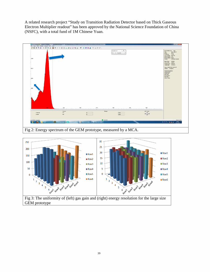
A triple layer, 30*30 cm2 (active area) GEM detector based on new stretching method (NS2) has been successfully constructed, as shown in Fig 1. The NS2 method allows easy repair/replace of the GEM foils. The prototype is installed in the test setup and studied with a Copper k-edge (8.9keV) X-ray source. The gas mixture consists 70% Ar and 30% CO2. The output signal, amplified by a charge-sensitive amplifier and a shaper, is feed to a multi-channel analyzer (MCA). The recorded spectrum is displayed in Fig 2, and the gas gain and energy resolution are extracted. By moving the X-ray source on the platform, the uniformity of the gas gain and energy resolution is measured. Fig 3 shows the results at 6*6 X-ray injection positions (dark circles at the back of the GEM base, Fig 1C). Although the energy resolution is rather uniformly around 20-25%, the gas gain differs by about 100% over the whole active area, especially near the border of the GEM foil (row/column 1/ 6). This is understood as the consequence of over-stretching of the foil, confirmed by inspection after dissembling the prototype. A second version is currently under design to resolve this issue.
38
A related research project “Study on Transition Radiation Detector based on Thick Gaseous Electron Multiplier readout” has been approved by the National Science Foundation of China (NSFC), with a total fund of 1M Chinese Yuan.
Fig 2: Energy spectrum of the GEM prototype, measured by a MCA.
Fig 3: The uniformity of (left) gas gain and (right) energy resolution for the large size GEM prototype
39
Plan: Update the APV readout with new ARC II (controller), re-configure the gas box to allow 3cm drift and absorption length, replace gas with Xeron mixture (80/20). Test with x-ray source before a test beam. Possible test beam in the summer time. With the positive fund from NSFC, difficulty in obtaining visa for visitors in last few months, and additional responsibility change, we have proposed to use the fund for a joint two-year post-doct position with Dr. Lijuan Ruan’s Early Career Program Award on a 50/50 over R&D/STAR Analysis. Details will be presented at the January meeting.