32
I .t RESEARCH·DEPARTMENT METHODS OF THE PERFORMANCE OF LENSES Report No. T.039 Serial No. 1953/20 Report vVTitten by: W .1J. Sproson (w. Proctor Wilson)

I .t
RESEARCH·DEPARTMENT
METHODS OF ~mASURING THE PERFORMANCE OF LENSES
Report No. T.039 Serial No. 1953/20
Report vVTitten by:
W .1J. Sproson (w. Proctor Wilson)

Report No. T.039
FOREWORD
This report is a revised version of an~ticle which appeared
in the Spring 1953 issue of the BBC Quarterly, under the title
"The Measurement of the Performance of Lenses l1 • The present
report incorporates some new work which has been done since the
published article went to the press: in particular, a method
is given for transforming the squaro wave response of a lens
into the corresponding sine wavo response.
in detail in Appendix 3.
This is described

.REJPOlt1'..1!.o • ..1..! O"~_
METHODS OF .l.~~ THE PERFOR1V[ANCEOF jJENSES
Section Title
1 INfJ.'RODUCTION - - - - - - - .. - - - - - - - - - - - 1
2 . DEFINITION OF "1i'REQUENCY CHARAC1rERIS fnCI1 - - - - - 2
3
4
METHODS OF MEASlTREMENT - - - - - - - - - - - 4
Visual - - - - - - - - -Photoelectric Method - - - -
4 6
3.2.1 Using a Set of Square Wave Grating Patterns - - - - - - - - - - - - - - 6
3.2.2 The Unit Step or Unit Impulse Method - 7 3.2.3 Comparison Af Photoelectric Methods - 10
CONCLUSIONS - - - - - 11
APPENDIX 1 (THE PERFORMANCE OF A PERFECT LENS) 12
APPENDIX 2 (A GRAPHICAL METTIOD FOR PFBFORMING FOlTRIER TRANSFORMS) - - - - - - - - - - - - - - 13
APPENDIX 3 (THE RELATION BETWEEN IrIIE SQUARE W.AVE AND THE SINE WAVE RESPONSE OF A LENS) - - - - - 16
REFER~NCES - - - - - - - - - - - - - - - - - - - 20
FIGS. 1 to 15.

Research Department REPORT NO. T.039
Serial No. 1953/20
CONFIDENTIAL
July, 1953.
Figs. 1 to 15.
METHODS OF MEASURING TREPERFORM.A1'JCE OF LENSES
1 • INTR ODUCT I ON
Lenses are used extensively in television, indeed each television camera has at least one lens and in certain applications such as television recording and standards conversion several lenses are used simultaneously.
In the early days of television, comparatively little consideration was given to the choice of lens for a particular camera; it is probably true to say that nearly everybody tool}: it for granted that any product of the optical industry was far superior in the definition ofVlhich it was capable, as compared with the definition of 405-line television pictures at their best. Thus, the photograph produced by any ordinary photographic camera exhibits bett~r definition than the pictures produced by a television system. In spite of these well known facts, evidence has be~Jn to accumulate that the choice of the lens used in a television camera can make a difference to the quality of picture. Television uses a nocessarilyrestricted band of frequencies, end in order to make the best use of the frequency band the ch .. ;racteristics of amplifiers and transmission circuits are normally kept constant to vdthin much less than I db from very low frequencies up to 3 MC/ s. Thereafter thore is a rapid and intentional droP? in fact a television channel approximates as far as is practicable to a rectangular spectrum.
Although the ultimate and limiting resollltion of a lens corresponds 'in television terminology to a frequency much higher than 3 1I1c/s, tlie response of the lens (mec,sured by methods e>bout to be described) shows a gradual drop to the limiting value 9 its "p>mpli tude vs frequency" response curve beers no resemblance to the rectangular response of, for example, the amplifier. Hence, although a Ions is capable of a very high limiting resolution, its response may well be several db down at a pattern frequency corresponding to 3 MC/s. The fact that it continues to respond to much higher frequencies is of no value to television. A photographic emulsion, on the other hand, will record to some extent most of these higher fr€:quency components and gives rise to a sharp picture because of the presence of these higher frequencies, even though their amplitudes are somewhat reduoe~o We thus have the paradoxical situation that television, although of relatively low definition, may make more critical demands on camera lenses than photography.

Let us novV' consider tho imago-forming properties of a lens in some detail. The image produced by a lens is an approximate replica of the object. There are two lllQin reasons why it is not an exact roplica: (1) wave nature of light, (2) aberrations. Either er both of those causos may bo rosponsible for the lack of perfection in the image. In practico, wo can say that at small apertures (f/22 or less) the wave nature of light is ~~e principal cause of imperfection. At large apertures (f/2 - f/9) the imperfections caused by the wave nature of light are very slllQll and in fact the performance of a lens is almost entirely determined by the aberrations. These may be listed as follows: -
(a) spherical aberration
(b) chromatic aberration
(c) as tigma tism
(d) coma
(0) curvature of field
(f) distortion
(g) flare
The first S:Lx are goometrical aberrations, of 'which (a) n.nd (b) are present for axial images, (c L Cd), (e) and (f) being additional errors for off-axis points. Flare is produced by multiple reflections and scatter from the var.ious interfaces in the lens, and is reduced conSiderably by "blooming" the surfaces.
2. DEFINITION OF "FREQUE1TC'( CHARACTERISTIC" - ~-.-..--.---
It is possible to neasure tl ... .a effects of the various geometrical aberrations separately, but although this may be of great interest and value to the lens designer, it is not easy to form an overall picture of the performance of the lens from such data •. Following_ the concept of "frequency characteristic ll as applied to a four-terminal electrical
. network, this note describes some methods which have been used to meaSure the "frequency charac teristic 11 of a lens ~ Firs t wo dofine what is meant by the frequency characteristic. Suppose that the test object is a grating pattern with equal b1ack-whito spacings and of high contrast ratio. Figure 1(0.) shovm the intensity distribution in tho object. The intensity pattern of' the imgo formed by the lens will of necessity sh~r same rounding of the cornors - tho contrast ratio is also

3.
likely to suffer, e og. Figure l(b). The values of the maxima and minima of the intensity pattern are obser-v'ed and. the modulation is calculated as
I I . max. - nun. I + I . max. mJ.n.
If a range of grating patterns is available, then the curve obtained by plotting ~ against frequency (i.e. number of patterns per mm in the image plane) is oalled a frequency oharaoteristio. This information about the lens for axial and off-axis points gives a statement of the lens performance that includes the 0ffects of all tho aberrations exoept distortion. The goometrical distortion of a lens is usually small and can be measured separately if information about it is
'required (eog. in photogrammetry). The geometrical distortion of electron lenses is in general much greater than that of optical lenses, but this subject is outside the sc ope of the present paper 0
The measurement of (Imax.- Imin.)/(Imax.+ lInin.) of the intensity pattern of the image is one method of stating the response. It is a measure of peak modulation to a square wave -wst pattern. However, it is open to tho objection that the intensity po. ttorn of a Ions image might show a rounding of the corners without the loss of peak modulation. NIeasurements to date have not revealed any such lens, but it is an objection. There is the further' objection tl1.at the response to·a square wave pattern involves many frequenc ies (tde Fourier synthesis of a square wave requiring about 10 harJ'lonic terms before the rec ol1struction bears a close resemblance to the original) whereas one would like to know the lens performance at one frequenc;)To Schade(l)doscribes a flux responso factor for a lens and this meaS1J.re~Jlent amou."1ts to
aroa AB - area BC aro-i-']ffi-T-aroo.BC as shown in Fig.l(t)
This is, in effect, a measure of the aroa enclosed by the positive and negative excursions about the mean of the response waveform and is a more sensitive indication of the defect of the image. H~rever, the most satisfactory measure of the performance is probably the peak modUlation when the test pattern has a sinusoidal intensity distribution. Figo2 shows these three response functions for a perfect lens (i.e. Cl.
lens limited only by the wave nature of light). The method of cal-culation is indicated in Appendix 1.

3 Cl :METHODS OF ~l1EASUREME:IIT
3.1 Visual
This method was suggested by a paper of Selv-ryn and Tearle. (2) The apparatus oonsists of a device which varies the contrast of a test objeot while maintaining constant peak brightness as shovm in Fig.3. A and B are two light souroes consisting of snnll tins in whioh there are 36 W. 6 V. oar headlamp type bulbs. The interior surfaoes of the boxes are matt white and the exterior surfaces black. A sheet of opal 040 completes the light souroes. PI and P2 are sheets of polaroid oriented at right angles so that the planes of ~olarisation are mutually perpendioular. T is the test slide and M is a vaouum deposited mirror with a 5010 refleoting and 5Wotransmitting, spectrally neutral coating. P3 is a third sheet of polaroid which can be rotated about an axis perpendicular to its own plane. Such a device gives constant-peak illumination but varies the relative intensities from the sources A and Bo L is the lens under test and N is a microscope used to examine the aerial image produced by L. Both 16 mr,l and 4 mm apochrornats were usod as objectives with a XIO compensating o;)Te-piece. The test pattern is one of two slides supplied by the NaP.L. and consists of a set of horizontal and vertical patterns of gradually decreasing spacing. Fig.4 shows a magnified version of the test slide. Each slide has 40 patterns, the first covering the r~ge 2.51 to 17.2 patterns/mm and the second giving 10.2 to 70. patterns/nrrno Even at the highest frequency these N.P.L. test patterns show no rounding of the corners of the individual reotangles, when examined under a miorosoope of sufficient power.
The method of using the apparatus is as follows: the soale of .£olaroid P3 is oalibrated to produce values of log a. of 0, 'I08, T.6, 1.4, eto., down to a level of oontrast for whioh the eye can no longer resolve the coarsest of p~tterns. For each of these values of contrast, the image of the appropriate test slide as formed by the lens L is examined and by visual inspection the last pattern whioh is discernible as possessing two gaps with the correct orientation (i.eo vertical or horizor.tal) is noted dovm. As the oontrast of the test slide pattern is reduced, the frequenoy of this limiting pattern will be reduced. A plot of log a. against J:!attern frequenoy will b9. the reciprocal of the reqUired frequenoy oharacteristio - reciprocal because instead of direotlymeasuring the output for oonstant input we 0.1'0 varying the input (oontrast of test objeot) and keeping the output constant (minimum contrast ut whioh the e~re oan perceive detail for constant peak brightness when aouity is not limiting) 0 The niost difficult part of the experiment is to determine the threshold at which one black-white edge in the whole field of view is just perceptible. Th:i.s corresponds to the contrast required for a very low frequencYI so low in fact that

5.
one transition is occupying the whole of the microsc ope field. This is cleal,'ly the nearest practicable approach to a "D.e. 1l measurement. This threshold must be determinod separately for both the 16 mm and 4 nun microscope objectives as their contrc"st characteristics have to be eliminated from the final rosults 0 As 8.rl indication of the extent to which this-was done on ono occasion, Fig.5 shows a plot of log ~ against pattern frequency for Cl. 3 11 f/2 lons exa.'tJlined at f/8 on axis" The individual contrast thresholds for the two objectives have been taken into consideration and normalised: Fig.5 shows that there is tolerably good agreement between three sets of results 0 Hence we may conclude that the curve shown represents the lens characteristic alone 0
A few off .. axis measurements were also taken. For this purpose, that part of the apparatus which formed the variable contrast test object was mounted on a second optical bench which was perpendicular to the main optical axis 0 The microscope N was in fact a travelling microscope capable of vertical and lateral movement. Thus the test object could be moved off axis and the microscope ~ovod to follmv the image formed by the lens L. The setting up of both lens and travelling microscope is most critical since the microscope focus must not bo altered for off-axis measurement's and it is essential (i) that tho optical axis of lens L shall be parallel to the main optical bench (H) that the travel of the microscope shall be accurately perpendicular to the optical axis"
It will be observed in Figure 5 tha..; there are no reliable experi,mental points in the region 0 to 80 patterns per mrn. If we are interested in our lenses from the point of view of performance in a television system, this is a most serious defect since it means that we are performing a gross interpolation for all the frequencies which a television channel can handle. On acc ount of the difficulty of measuring the threshold accurately it would seem to be almost impossible to obtain information about the performance of the lens in the 0 to 50 patterns/mm range by this method. (fiote that 3 Ma/s on a 20 x 27 mm photocathode with a 405-line system. corresponds to a.pproximately 10 patterns/mm and that O~l 16 :mm television recording cameras the limiting requirement for 3 Fic/s is 53 patterns/mm.) For this reason certain photoelectrio methods have been investigated which are capable of supplying accurate information in the lmver frequency range.
There is also the objection for the above method that plane polarised light is used and althou.gh this is scarcely likely to affect the axial performanoe, it cannot be assumed that off-~~is measurements would be corroct.

6.
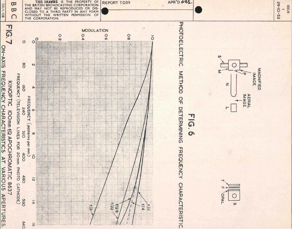
3.2 Photoelectric Method
3.201 ~jng a Set of Square Wave Grating Patterns
The test object for this method is a high contrast grating pattern with equal black and white spacings. A set of these having 10, 20, 30 00". 100 complete patterns on a standard 3-t" x 3~" lantern slide was used. The arrangement is nOVf as shown in Figure 6. B is the light source, F is a neutral and/or colour filter, T is '~e grating test pattern" L is the lens under test. N the microscope (used without an eyepiece)" M the multiplier photocell mounted in a li€jht-tight box with a vertical or horizontal slit P. The box houSi:1g the multiplier photo-cell is attached to the vertical column of a travelling microscope stand, the microscope having been removed. The lens forms an image of the test object and this is magnified by the microscope objective and imaged on to the front surface of the multiplier box. With a vertical slit and vertical test pattern. fluctuations are observed as the photomultiplier scans the image with a horizontal movement. For each test pattern, ti1e maximum and minimum readings of the photomultiplior final anode current are taken. The modulatiorf- is again calculated as
Cl, ::
where the I values are the photomul tiplie currents. .An adjustable zero is used so that the photomultiplier "darkll current is not included in the measured values. A plot of Cl, gives the lens characteristic for one particular aperture and One orientation (i.e. on axis or a specified number of degrees off axis).
For off-axis points the lens is rotated about a vertical axis through the appropriate angle and two measurements are taken - one with a vertical slit and vertical lines and the other w-{th a horizontal slit and horizontal test pattern lines. The diroction of scanning in the latter case is changed to vertical. In this way the ts.ngontin.l and radial characteristic curves arc found.
H This va.lue includes the combined effect of both the lens under test and the microscope objective. At the 'low pattern frequencies used, it is reasonable to assuroo that the performance of the microscope objeotive is good 0 .

7.
A diffioulty arises over focusing the image for off-axis measurements. If the field of the lens under test were perfeotly flats i.e. defect (e)' zero, then the optimum visual focus for the off-axis position would be the correct plane in which to take the measurements. However, this cannot be assumed to be so and in fact off-axis measurements involve a subsidiary determination of the flatness of field so that when this is known the image can be defocused from its optimum position in the correct direction. and by the measured magnitude.
An alternative and more elegant way of circunwenting this difficulty is to use a nodal slide which gives automatic compensation for the l/cos e increase in distance for off-axis values. It is, however, essential to use collimated light with oche nodal slide.
Figure 7 gives some axial meaSUreITlents on a 100 mm f/2 lens. The apertures used were f/2, f/2.8, f/4, f/11 and f/22. A rapid improvement in performance is observed upon stopping dovm from f/2 to f/4. This appears to be typical of all lenses measured so far ... namely that the performance of a lens is always better when stopped down by two or three stops from its full aperture. The deterioration of the frequency response at f/22 is due to the wave nature of light and the use of a very small aperture. At this aperture the lens aberrations are not the controlling faotor in the lens performance (see Appendix 1 and Figo2 for performance of aberration-free lens).
Figure 8 gives the on-axis and off-a' is performance of this same lens at full aperture. The off-axis values are in this graph unduly favourable to the lens, as they represent the optimum focus althoughcurvature of field is certainly not absent.
Apart from serving to illustrate the method, the results shown in Figures 7 and 8 show that even at the low frequencies used in television, there is a quite definite loss of contrast due to the lens and the lens cannot be assumed to be very much better than the remainder of the television channel, as was formerly assumed by many workers.
This method was suggested by the similarity of the performance of a lens to an electrical network. Suppose we have a straight edge imaged by a lens. Then the image should show a very sharp transition between the shadow and the illuminated part. The shape and gradient of the transition curve (intensity vs. distance in irnage plane) will give an indication of the frequency response of the lens. This may be compared with a four-terminal electrical ne~lork, where a unit step is applied at the input terminals and the time function of the response is

8"
measured at the output terminals. In the optical case time is replaced by distance and frequency becomes pattern frequency measured in pat~erns per mm and of dimensions distance-loAn example may serve to clanfy this. Fig.9 shows the measured "unit step" response of a lens, i.e. the intensity distribution found when a narrow slit Scans the image of a single b1ack-to-white transition. The steepness of' slopo of the transition will be a measure of the frequency response and the appro~ priate Fourier transform will ,give the required result.
A curve fitting method was first tried which is although it has since been abandoned. Thus, it can space function
f(x) = ; + ~ arctan (~)
where k is a.constant
of some interest be shown that a
and x is distance in the image plane
transforms into the freQuency function
t.p (w) = e -k/ w I where w = 2~ x pattern frequency.
Fig.9 shows the arctan function with a value of k adjusted to give coincidence over the region of steepest ~lope. This value of k also defines the exponential frequency function shm~1 in FigplO. The
. Fourier transform shown in Fig 010 is compared with the experimentally determined frequency charactoristic and the agreement is soen to be tolerably good. There are two reasons apart from experimental error why the agreement should not be exact: (a) the arctan fUnction does not give an exact fit with the experimental data, (b) the Fourier transform is equivalent to the frequency response for a set of sine wave test patterns, not the square wave pa-I:;torns that wore actually used. The first ')f these two reasons is why curve fitting was abandoned in favour of the general method introdt'_eed bolov! and described in deto.il in Appendix 2. The seccnd objection co.n be overcome by tro.nsforming the square wn.vo result to El sine wave response as shmVIl in Appendix 3. The result of doing this is also shown in FigolO a~d the agreement is seen to be improved.a The significance of a sine wave response is that it is relev8..L"lt for any problem involving a l:lnear passive network. Thus, if we wish to apply lIaperture correction" for the high frequency losses produced by the lens, the sine wave response gives us the figures from which to calculate the requisite gain vs. frequency characteristic for the amplifier. Alternatively, if two lonses aro

- 9 -
used in cascade, the overall response is the product of their sine wave frequency response.
To return, however, to the general problem of evaluating the Fourier transform, we may express this in the following way: given an experimentally measured spacG function f(x) , WG are reQuired to find the rGlevant frequency function, knovdng that the original tost pattern is eQuivalent to the electrical unit ~t0p. Using tho operator p, which is eQUivalent to jw, the integral is as follows:
;/100 = p / exp (-px) f (x) dx
,i-co where ~(p) is the freQuency response in a generalised form whioh includes phase as well as amplitude. For an e~ial measurement we know that the symmetl'Y of the lens implies no phase che..racteristic, since the image is symmetrical. However, the phase term has an optical significance for oif-axis measurements and is oQuivalent to an asymmetry of the image intersity distribut:t.on such as occurs with coma.
The evaluation of the Fourier integral has been performed in practice by a graphicl.",l method which is described in detail in Appendix 2. This moans that we are no longer restricted to curve fitting, but are in a position to transfOrm c,ny observed space function into a freQuency characteristic ,vi th as much accuracy as the eriginal experimental data permit.
Another method of testing is to use a fine slit source, this corresponding to the unit impulse method of electrical testing. The apparatus remains as shown in Figure 6, apart from the use of a narrow slit as test object. The image of the slit shows some broadening and a typical intensity pattern is shown in Figure 11 - this being a measurement on a 50 mm f/l.5 lens measured axi.ally at f/2.
Th0 unit step and unit impulse methods ""ro directly relatod, sinco the derivativ~ of the unit step response is in fact the unit impulse response. This is shown in Figure 12, which gives both the unit impulse responso and the dorivative of tho unit step response for the 100 mm f/2 lens at full aperture on 8~is. This S0me lens was tested vii th sQuare '{~:re test patterns ana. also vii th a set of sine wave tost patterns (supplied by M:r. Selwyn of Kodak Research Laboratories).

10.
The frequency range of the sine wave tGst objects was not as great as would have been liked, but there is a close similarity of the sine wave test pattern result with the Fourier tra:nsforrn of the two transient methods of testing - Figure 13. The square wave test pattern result is seen to bo slightly but significantly different from the other three results. Hovvever, when transformed by the method given in Appendix 3, it yields a result which is in reaso:r.ably good agreement with the other three methods.
302.3 Comparison of Photoelectric Methods
For the purpose of g;iving a general assesSJl1ent of a lens, :the peak modulation to a square wave test pattern gives a good general indication of perforr~nco. The response of the theoretically perfect lens to this type of test pattern is known, so that comparisons of one lens with another and with the theorotical ideal are possible. Further I it is a relatively easy matter to malee good square wave test patterns up to quite high frequencies.
If the sine wave respcnse is required then there are four alternative methods .. three of which give the sine '.<rave result more or less directly, the mathematical transform of the square wave result consti tuting the fourth method. Which method is finally used is a matter of experimental convenience. If the square wave test pattern method is used, it is desirable to cover the frequency characteristio certainly to a value where the response is 0.5 and if possible up to the out-off frequency. This makes the transform to the sine wave results a matter of oertainty rather than· plausible conjecture. On the other hand, the transient methods of testing are not very convenient in the present state of development of the apparatus, as they involve a fairly lengthy set of readings of intensity versus position of soanning slit during which the conditions of operation of the Whole apparatus must remain very steady. Apart from light sources and amplifiers,photomultipliers are not too steady in their response, as dark current and gain increane for some time after first switching on. It is not difficult to design a set-up for the transient method nSing' automatic scanning and either cathode-ray-tube or pen recorder for wri ting dawn the transient response 0 With this modification, the unit impulse method would be worthy of serious consideration for routine measurements. . Alternatively, steady state measurements with sine wave patterns would be equally valid - when we have a set of sine wave patternswitg)an adequate frequency range. It is of interest to note that Schade( has changed from square wave to sine wave test patterns in his latest paper 0 Further work is probably required bofore any final. decision is taken, but there seoms little doubt that all tho requirod data oan be oasily obtainod from tho results of square wave test patterns.

110
4. CONCLUSIONS
(a) The performance of the lens in a television system is not superlatively good l and proper choice of lens needs to be made for the best results.
(b) A visual method has been tried out for measuring the frequency characteristic of lenses 1 but this' has been abandoned in favour of photoelectric scanning methods as the frequencies used in television systems are relatively low.
(c) Fairly extensive photoelectric measurements have already been made using square wave test patterns. One important result from these measurements is that all lenses give a better performance when used at one or t\.vo stops less than their full aperture.
(d) Four photoelectric methods are available for measuring the sine wave rosponse of a le!2S. This rosul t is of greater value for analytical purposes ~~an the square wave response.
-12 -
APPEHDIX 1
THE PERFORNLANCE OF THE PERFECT LEHS
The response to unit step of a perfect lens (i.e. one limited by diffracti~~)and not by any geometrical aberrations) was first evaluated by Struve. Using this as a basis, and assuming non-coherent lighting, the intensity pattern for a s,eries of successively displaced positive and negative unit steps was aided up to give a close approximation to an infinite grating pattern. The peak modulation to square wave response was then diroctly evaluated and by a single integration process, the flux response fact~r to square waves was also computed.
The response of the perfect lens to sine wave test patterns was calculated from the derivative of Struve's result (which is equivalent to the response to unit impulse). This was then graphice~ly integrated to obtain the Fourier transform by the method described bolow. In this way the curve shown in Figure 2 was obte.ined. This curve relates to monoc hrorhatic light.
Tho responses sho~vn in Figure 2 d.iffer slightly from those of some other workors - one of the points of difference being that geometrical points are usually taken as the original test object and the diffraction im8~e of these are used to calculate the modulation depths. If one were~_lculating the resolution of two stars, then it would be right and proper to consider point sources, but since for many purposes, parallel bar t est patterns are used, the unit step would appear a more logical starting point.
------- .... -
- 13 -
APPENDIX 2
11 GR.APHICAL l\IIBTROD FOR PERFORMUfG FOURIER TRANSFORMS
(Due to G.G. Gouriet)
Given the time function f(t), Fig. 14, this can be spmpled at sufficiently frequent intorvals and the ordinates measured - the notation being as indicatod in Fig .• 14.
We can reconstruct the set of unit impulses which amplitudes proportional to impulse as
we hav0
f(t) ~ ~~ lrocos ",t d<O
<I -co
original time function by considering p" are displaced in time and have relative the ordinates in Fig. 14. Writing unit
wt dw
(00 w (t + T) dw + A -1 / cos w (t _ T) dw
2~ I.I-CO
+ A2 /~~os w 2~
<J -co
. A 2 /"
(t + 2T) d<O + ;~100 cos w (t - ·2':2') dw
+ ••••• where T is the timo interval between successive samples.
* In the optical cP.se, f( t) would bo replaced by f(x).

Then
1 f( t) "" 2'Jt
1 =-
2'Jt
- 14-
",00
/ I
! . J
V-ro
(Ao cos wt + 1~ cos wt cos roT - Al sin wt sin wT
+ A_I cos <.at cos <.aT + A_I sin <.at sin wT
+ A -2 cos wt· cos wT ... A:"'2 sin wt sin wT
+ •• ••.••• ) dw
+ ~-l - Ar) sin wT + (A_2 - A2) sin w2T + ':~'_.P'~hasS~e·n.:td:r dw
The expressions in the square brackets are the ... = a...
quadrature components of the frequency functiono
Thus
Q(W) =
The highest frequency for which these expressions are valid will depend on the sampling intorval T.
1 We may write T = 2f where tc is the highest frequoncy in which
we are interested. C
Henco
Q(x) "'"

- 15 -
where x = f/f and varies over the range 0 - 1.0. c
The modulus M(x) ~ JG(X)] 2
and the phase e(x) ~ axe tan [ Q(x) / P(X)]
In the case of the intensity distribution of axial images, the distribution is symmetrical about the centre and Q(x) :: O.
The values are normalised by dividing p(x) by p(O) which is tho sum of the vp,riousordinates.
Wi th the aid of a table of mul tiple cosines and a calculating machino, a Fourier transform can be evaluatod quite spoedily by this method. An indication of the n.ccuracy is tho nearness to which pCx) approaches zero as x ~ 1.0.

- 16 -
APPENDIX 3
THE RELATION BETVillEN THE SQUARE V~1VE AND SINE WAVE~ONSE OF A LENS
Consider an ideal square wave with equal mark space ratio, of unit ampli tude and repetition frequency (I) !27i.o The Fourier series is
. 0
.sin (2n - 1)
2n - 1 0" X '" ,?7i. .~ .:::::
Wo
If the square wave is applied to a system with a sine vuwc frequency characteristic ~ ((u) then the output vliU be
F(W x) == .! o 7i.
sin (2n - 1)
2n - 1
W :x:o
The maxima of this function will occur at
W :x:o 7i.
== -2 57i. 97i. , 2" ' 2"" •••••••• ·etc.
at which points sin (2n - 1) Wo t will have the valu0s
1.0 for n odd
.- 1.0 for n oven
The maximum values of F(W x) may thus be wTitten as a function o
of W :o
F(W x). == Few) o max 0 max
n=co
~.L~ 7i.L
n=l
i_1)n+l
2n - 1 ~2n - 1) w~J This is the peak modulation to a.square w~ve pattern defined in terms
of the sine wave response.
There is no simple general method for expressing ~(W ) explicitly o

- 17
in terms of F(w ) as a continuous function of w • . 0 max 0
In: practice, however, F(w ) ,viII be measured at a relatively " omax small number of d~screte frequenc~es: Let these be, say, ten in number
and harmonically related as follows:
...... lOw. o
and let it be assumed that w is so chosen that there is substantially o zero response for w1- llwo '
We can v~ito down the following equations:
F(wo)max = ~ f;(wo
) - P(3Wo) + P(5wo ) _ P(7wo) + P(9wo)J 1- 3 5 7 9 "J
F(2oJo)max - ~ ~(2") - ~(:",o) + P(~O<o) ]
F(3w ) = 'd o max 1t
• • • •
F(lOW ) = it. p(lOw ) o max 7t 0
- 18
'1\< t F(&'> ) F(lCko) ] ~(2(JJ 0) F(2W ) -I'- 0 ma..~ o max =-
4 o max 3 5
~(wo) 7t two}max F(3wo)max F(5wo)max F(7"'i)max.] ... - + + 4 3 5
Hence the sine wave response for ten equispaced values of frequency hal\'! been determined, In most practical casos this would be. found to define the frequency characteristic pew) with sufficient accuracy. The extension to 20 terms is not difficult and can be used if greater accuracy is required.
The response cUrves vfuich describe the performance of lensos are e.ll of the low pass type with a more or less gradu~,i cut-off.
The following five equa.tions wore considered to sec whether there is any approximate general relationship between the squ8.re wave and sino wavo responses.
Y =l.arctan 7t
\. -wc \j 2e
-0 -2WC/' ••• ~ ••• o ••••••• (1)
y ... sech;r ........................... " .......... (3)
2 Y =- a-X. ................ po ........ e· ..... "" ......... ..( 4)
Y = H(x) whore H is a function derived from struve and fits tho perfect Ions (Fig. 2) ••• o.~ •••••••••••••••• (5)
The relationship between the squaro wavo and sine wave responses was evaluated for these functions and the results are expressed in the following table in torms of a frequency scale normalised at .the 50% value. K is the multiplying factor by which the square wave response is multiplied to give the sine wave rosponse&

- 19 -
. K
Function No.
f/fO•5 1 2 3 4 5 Mean
O· 1.00 1.00 1.00 1.00 1.00 1.00
0.2 0.95 0.94 0.97 0.96 0.95 0.95
0.4 0.90 0.91 0.88 0.90 0.86 0~89
0.6 0.86 0.82 0 .. 83 0 .. 83 0.79 0.82
0.8 0.845
0.7 85
0.82 0 .. 795 0.78
5 0.81
1.0 0.83 0 .. 785
0.80 0.785
0. 785
0.80
It will be ubserved that for the range of functions considered, a mean multiplying factor is available which is correct to 4% or better for all frequencies up to fO • The fr.qquency response curves of most lenses lie within the rarlge of functions considered. Fig. 15 shows these functions plotted over the frequency range 0 to f • For any curve lying vdthin the envelope of the ourves shown in ~i~. 15, it is probably legitimate to take the mean conversion factor as given in the above table. The inherent assumption in doing this is that the behaviour of the l?ns respo~se beyond fos is :easonablo and lies within the range of functl.ons consl.dored. If ~llere l.S t),ny doubt about whother a particular Ions characteristic can be treated in this way, the simple sampling technique given at the beginning of this appendix can be applied. It is felt, however, that in most cases this will bo unnecessary.
- - - - - - - - - - - -

- 20 -
REFERENCES
(1) Schade, O.H., R.C .A. Review, .2,.,ppo 246-86, 19480
(2) Selwyn, Eo W.H., and Tearle, J .1., Froc. Phys. Soc., .2§., p. 493, 1946.
(3) Schade, O.H., J. Soc. Mot. Pict. andTel. Engn q .2.§., pp. 181~222, 1952.
(4) Selwyn, E.W.H., Photo Journal, 88B, pp. 46-57,1948.
(5) Struve, H., Ann. Physik u. Chern., 11, pp. 1008-1016,1882.

ISSUE
I 29~IO~S2
a-M 0 r-: I-a:: 0 Cl. w a:: I4.Z,),1: ....
1 00 0",0 - 0
~~« .... z ««0>-0 wo zu; OA.o<", «w -::ouz~ u:::>-w w"o>-A. :I: Z 0"" I--«~z 1-0.. w "'V'w~~ -<a::
U 0- -~owa::~Z ~<ClDi 0 ~Ol-I- ~ ~~~<~~
:I: 01-2 !!!'!!>-I-I-%1-< « "'-1: 0 =>0 « wOu
CID "':1: w~ot:w ~<u ~ ~
BBC
LIGHT INTENSIT.Y .
..-- - - -
DISTANCE
LIGHT INTENSITY FIG 1(0)
-------------~
Imox. - -- -MEAN
Imin
FIG I (b) NTENSITY PATTERN IN OBJECT & IMAGE PLANES FOR A RELATIVELY LOW
TTERN FREQUENCY. AT HIGHER FREQUENCIES THE IMAGE INTENSITY
0 ·8
0-6
0-4
FIG. 2
APPROACHES A SINUSOIDAL VARIATION.
100 200 300
PATTERN FREQUENCY IN 10~0 UNITS
FREQUENCY CHARACTERISTICS OF THE PERFECT LENS (MONOCHROMATIC LIGHT)

,
ISSUE I
29-10-52
BBC
D L
FIG. 3 VISUAL METHOD OF DETERMINING FREQUENCY CHARACTERISTIC.
- - - - - -- - - - - - - - - -- - - - - - ========== ••........... - - - - - - - - - - - - -Ill' III III III III III III III III III 11\ III III III III III III III III III III III III III III ., ,. In ~ • ••••••••••
FIG_4 MAGNIFIED VERSION OF THE N.P. L. TEST SLIDES.
t-----:--_-t THIS REPRODUCTION DOES NOT DO JUSTICE TO THE ORIGINAL OWING TO THE LIMITATIONS OF THE OS/I / 08 PRINTING PROCESS.
I

I ISSUE if IT U1 m lHfh ; :1 IWt H 'r~tltm iUl H tt'" cHI
I ~ [ G1 tl ~Im IH ' ri !i )tfit'ffi #lrtl ~~+, 29-10-52
tll '::H f+~ ~t It\! H If! Hi: unHn it ,HCf
illi ~m :tw, 11,; "~ ~: I ~jrl l 1; fJ rWl ~t·t~ ~ ~
!.ill- ~ lil IH ~j} ,i t j; i.li tll~:~ I':..; m~i ,;:>+!:t±
J-r ~m rH l!qi1f ~ tim :'!;? nIti , 'I ;j!~ I ~:;f rUTI;:t1.! H4
~ IHr li 11 p,n fh;Yf;: ~ ·~~rr~1l frtTtm I~ El m1 PH : Ht[ i;~ ~H 1i:J4
Imp ~1 Ht I illt ~±: 1:4 <1n l !; liiHPi;' t~ ~ ~n lll{~ t: tD lifilt'!:' fm
.M- rr th-~th ,rn,' i+ t+ l-r ch
tt, 'F\- t~
tit I$i-;, lttf!~ g'. il~ , I-f tt.:l! I,:rr' 'c-;';
';:.:: It e H+ fl
Ig ~\
~ a. cC -"'" m
-'·8 iI '- 6
,.4 0- -I"l 1- 2 0 .-: lege( I- - -~
, -"", H+ =rr:
I ~ •
Tt!:!""-'C: .
I+: 2-8
! ..... >..~ , o tG '"- \..
2-6 !,-E~ X. '-"0 IU c: ns c: g. C'C ~ Q.. c: g 'E - ...
.Q ~ 2-]~]., ~ 0 o.&;
Q,- u
~ ~ .~ ~ . 2-~ v"O::IC; coo
.g~g~~ 2· r3 'Z l 0
c;:: "" ""0 0-'u ~ ., E ..... 0 SO 100 150 200 250 30 0 Cl "C ~ '- ~ ~g"l:)..2 FREQUENCY (pQtt~rns p~r mm) . .... L. 0 et
.£co ~ ~-5 t.s:: L ,.,_
FIG.S t'IJ .!! 0 ..... C .,, "LtJo-C
• aD"" 0 .... . -.. u ..
3"f/2 LENS TESTED f /8. 1: " ... L. ..,. TAYLOR TAYLOR & HOBSON AXIALLY AT .... ~ g ~ E
BBC . DS/44/P
tp
tp
()
" G) . ...J
o Z I »
X (J\
THIS DRAWING IS THE PROPERTY OF I REPORT T039 THE BRITISH BROADCASTING CORPORATION ' AND MAY NOT BE REPRODUCED OR DIS-CLOSED TO A THIRD PARTY IN ANY FORM WITHOUT THE WRITTEN PERMISSION OF THE CORPORATION,
o
CD o
00
IV
o r\J
MODULATION (,) Q ~ (]\
o cD 6
"'TI :0 fTl 0" cfTlZ zO n"O -<;--1
'TI :0 I'T1 o C 1'T1(]\ zO n
~_ ••• ~.;..!f: nn ::r:»0 :00 »3 q3 fTl~ ::0 IV -» ~"O -0 nn (J\J:
»:0 ,0
3: ~l> :0-1 On cO) (1'''' W »-....l "0 fTl lJ --I C :0 fTl (J\
-< -==i'
'TI :0
B I'T1 r I'T1 S ~ ~ (]\ lillJlTI.: 11tH if
C/1 (5 Z
r Z I'T1 C/1
o :0
I\)
o 3 3 "tI I o
0% n -<
-i ~ o CD o n ~ I o o I'T1 VI '-"~
~ o
APR'D~ I
I "0 ::r: ~ 0 fTl r fTl n -I ::0
n
~ fTl
~ 0 0
0 ."
0 fTl ,
" fTl -:0 G) ~ Z 0' Z G)
"'TI lJ fTl 0 C fTl Z n -<;
n ::r: » lJ » q fTl lJ (J\ --I n
e
CI'~ o ' s:
s: ~~"tI ~ ~ G)'Tl p)-Z lj
-l> , s: ITl _l>lJ
G)-rD 1'T1~
-i", C==::J
'TI---
O~ ~~ r DJ
I\)
.0 ii; I '" - c o m I
VI I\)

" z o "'0 -i ()
OJ
n
o ~o " fTl3 _
"'03 G) ::tJ~. fTl t\J \(J CIll>
-i --t\J
----l> X
~ '-.../
THIS DRAWING IS THE PROPERTY OF THE BRITISH BROADCASTING CORPORATION AND MAY NOT BE REPRODUCED OR DISCLOSED TO A THIRD PARTY IN ANY FORM WITHOUT THE WRITTEN PERMISSION OF THE CORPORATION,
APR'D
...-------------11_
NORMALISED PHOTOMULTIPUER READING
:'- .FI r • 1 D\ . -'. . :
:.:0 ' ",W :>0 o Z C)
0:'-~'TIW l>~VI 0_ Zn -:0 :!!O (TI(fl on _ 0 ~" l>(TI
0< (TI(TI
,,:0 Z r_:.-
l>(TI. Z:O-l>. (TI VI
(fl
~ r (TI
'R':'-3 ~ ~O
:.VI VI
./.).
0-o
o
• 1 0-
~. , -I\J
o MODULATION 9 0
0-
, l'
I\) .0 _
I VI - VI O-C I "' VI
I\)

ISSUE
1 29-10-52
o "0:: 0.. c(
BBC )S / I
. I :_~.j' . .. __ 4_. ____ .
'12 . 14 16
.-t • • ~ ,
.LACK OF PRECIS! -s.:-MMFiIR;.Y~. ___ ·
OF INTENSITY. ~PAr:riERN. A~<+1I,.1T . :, . -.... ..". .. THE. C~I&E lS A~UJ~~q.i~AT4~'~: OF. EXPE~IMENr~r.._ .. E-~ .... _· _' _=:J
4·70 4'72 4 ·74 4 ·76 4·7B 4·BO 4·B2
RElATIV,E POSITION OF SCANNING SLlT~M'AGNIFIEQ) IMAGE PlANE(cm)
FIG.II ZEISS SONNAR SOmm flr·s LENS AT f /2 (AXIAL)
UNIT IMPULSE

ISSUE 2'
1 29-10-52
o '"0: a.. et:
0-f"')
o ~ Ia:: o ll. W et:
BBC 5/44 P
I-
-0, 06 -0,04 -0-02 0 -0 ' 02 CENTRE DISTANCES IN MAGNIFIED IMAGE PLANE (cm) ,
FIG.12 KINOPTIC IOOmmf/2AT f/2
COMPARISON OF UN IT IMPULSE & DERIVATIVE OF UNIT STE P.

J J\ ... o ""
THIS DRAWING IS THE: PROPERTY OF REPORT T.039 APR'O-M;l THE BRITISH BROADCASTING CORPORATION AND MAY NOT BE REPRODUCED OR DISCLOSED TO A THIRD PARTY IN ANY FORM WITHOUT THE WRITTEN PERMISSION OF THE CORPORATION.
0 ' 8
["---------1 e
r"· • .\ I 'r' ..
t\J
'" . "" 6-c I m
11I I\)
.:J .. , . .!·~1· ., .. _._-, . -.
. ;

",
VI
" C Z q 0 z (J)
" 0 ;;0
~ :t: () :t: () 0 z < rn :0 (J)
0 z
" » ~ 0 :0 (J)
:t: ~ rn DJ rn ", z () » r () c r ~ rn 0
"TI -~ U1
Thi$ drawing specification is the property of REPORT T.039 the British Broadcasting Corporation and may 110t· be reproduced or disclosed to a third party in any form without the wr itten per-mission of the Corporation.
A ~ Vl -- Vl 9 c UI m IV


