20 Commercial St. Branford, CT 06405 Phone: (203) 208-0806 Fax: (203) 488-4820 January 12, 2015 Connecticut Siting Council Ten Franklin Square New Britain, CT 06051 Attn: Ms. Melanie Bachman, Executive Director Re: 133 Gifford Lane – Bozrah, CT Dear Ms. Bachman, On behalf of New Cingular Wireless PCS, LLC ("AT&T''), enclosed for filing are One (1) original and two (2) copies of AT&T’s Notice of Exempt Modification for Proposed Modifications to an Existing Telecommunications Facility located at the above-referenced site. I also enclose herewith a check in the amount of $625.00 representing the fee for the Notice of Exempt Modification. If you have any questions, please feel free to contact me. Thank you, By: _______________________________________________ Name: Paul F. Sagristano Vertical Development LLC 20 Commercial Street Branford, CT 06405 Phone – 917-841-0247 Fax – 401-633-6202 [email protected]CC: Via Fed Ex William Ballinger, First Selectman 1 River Road Bozrah, CT 06334 860-887-6015 John & Betty Orr 131 Gifford Lane Bozrah, CT 06334 860-889-2689
Transcript
20 Commercial St.
Branford, CT 06405
Phone: (203) 208-0806
Fax: (203) 488-4820
January 12, 2015 Connecticut Siting Council Ten Franklin Square New Britain, CT 06051 Attn: Ms. Melanie Bachman, Executive Director Re: 133 Gifford Lane – Bozrah, CT Dear Ms. Bachman,
On behalf of New Cingular Wireless PCS, LLC ("AT&T''), enclosed for filing are One (1) original and two
(2) copies of AT&T’s Notice of Exempt Modification for Proposed Modifications to an Existing
Telecommunications Facility located at the above-referenced site.
I also enclose herewith a check in the amount of $625.00 representing the fee for the Notice of Exempt
Modification.
If you have any questions, please feel free to contact me.
Thank you, By: _______________________________________________ Name: Paul F. Sagristano
GENERAL COMMENTS ............................................................................................................................................................6
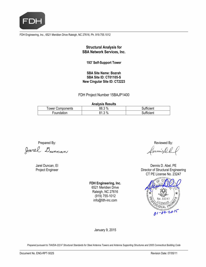
At the request of SBA Network Services, Inc., FDH Engineering, Inc. performed a structural analysis of the existing self-supported tower located in Bozrah, CT to determine whether the tower is structurally adequate to support both the existingand proposed loads pursuant to the Structural Standards for Steel Antenna Towers and Antenna Supporting Structures,TIA/EIA-222-F and 2005 Connecticut Building Code (CBC). Information pertaining to the existing/proposed antenna loading,current tower geometry, the member sizes, soil parameters, and foundation dimensions was obtained from:
Pirod, Inc. (Eng. File No. A-115466) original design drawings dated April 1, 1999Jaworski Geotech, Inc. (Project No. C98492G) Geotechnical Evaluation dated December 14, 1998SBA Network Services, Inc.
The basic design wind speed per the TIA/EIA-222-F standards and 2005 CBC is 85 mph without ice and 38 mph with 3/4"radial ice. Ice is considered to increase in thickness with height.
Conclusions
With the existing and proposed antennas from New Cingular in place at 182 ft, the tower meets the requirements of theTIA/EIA-222-F standards and 2005 CBC provided the Recommendations listed below are satisfied. Furthermore, providedthe foundations were designed and constructed to support the original design reactions (see Pirod, Inc. Eng. File No. A-115466), the foundations should have the necessary capacity to support the existing and proposed loading. For a moredetailed description of the analysis of the tower, see the Results section of this report.
Our structural analysis has been performed assuming all information provided to FDH Engineering, Inc. is accurate (i.e., thesteel data, tower layout, existing antenna loading, and proposed antenna loading) and that the tower has been properlyerected and maintained per the original design drawings.
Recommendations
To ensure the requirements of the TIA/EIA-222-F standards and 2005 CBC are met with the existing and proposed loading inplace, we have the following recommendations:
1. The coax must be installed as shown in Figure 1.2. The existing TMAs and proposed diplexers should be installed directly behind the proposed and existing panel
antennas.3. RRU/RRH Stipulation: The proposed equipment may be installed in any configuration as determined by the
client.
Structural Analysis ReportSBA Network Services, Inc.
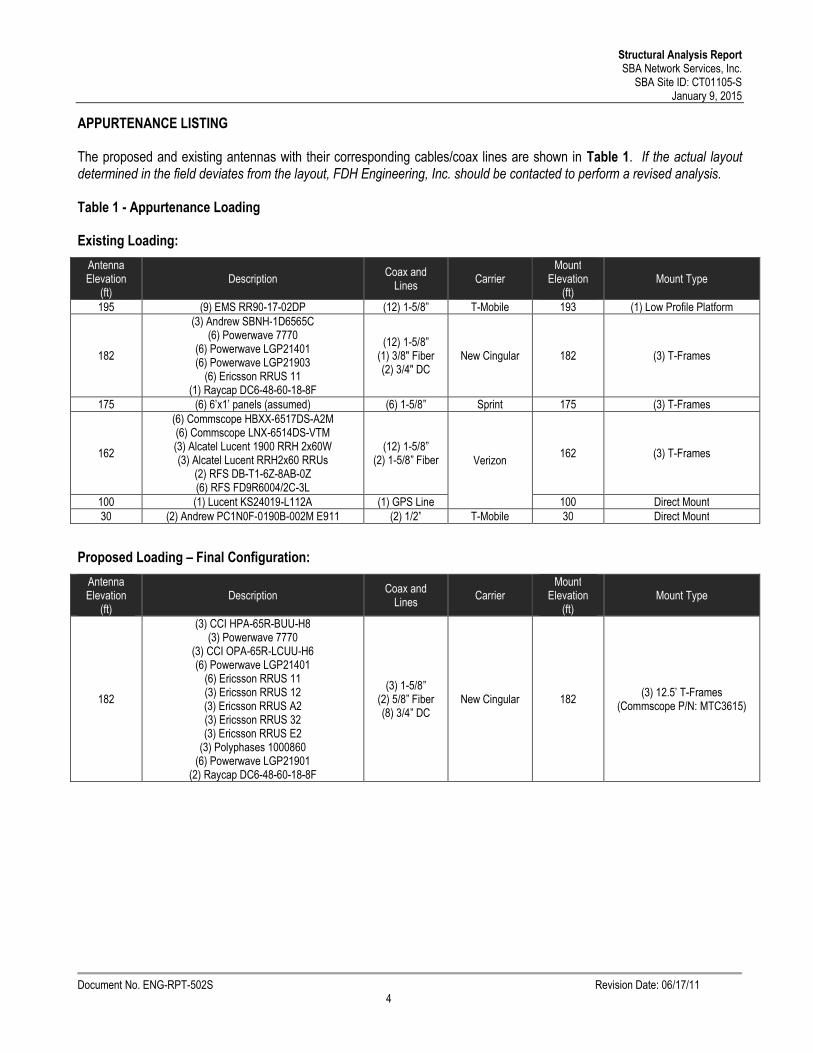
The proposed and existing antennas with their corresponding cables/coax lines are shown in Table 1. If the actual layoutdetermined in the field deviates from the layout, FDH Engineering, Inc. should be contacted to perform a revised analysis.
The following yield strength of steel for individual members was used for analysis:
Table 2 - Material Strength
Member Type Yield Strength
Legs 50 ksi
Bracing 50 ksi & 36 ksi
Table 3 displays the summary of the ratio (as a percentage) of force in the member to their capacities. Values greater than100% indicate locations where the maximum force in the member exceeds its capacity. Table 4 displays the maximumfoundation reactions.
If the assumptions outlined in this report differ from actual field conditions, FDH Engineering, Inc. should be contacted toperform a revised analysis. Furthermore, as no information pertaining to the allowable twist and sway requirements for theexisting or proposed appurtenances was provided, deflection and rotation were not taken into consideration when performingthis analysis.
See the Appendix for detailed modeling information
Table 3 - Summary of Working Percentage of Structural Components
SectionNo.
Elevationft
ComponentType
Size % Capacity*PassFail
T1 193 - 185 Leg 26.6
7.5 (b)Pass
Diagonal 1 11.7 Pass
Horizontal 3/4 7.8 Pass
Top Girt 1 1/4 4.6 Pass
Bottom Girt 1 1/4 5.3 Pass
T2 185 - 170 Leg 2 42.6 Pass
Diagonal 1 44.3 Pass
Horizontal 3/4 15.7 Pass
Top Girt 1 1/4 1.5 Pass
Bottom Girt 1 1/4 6.6 Pass
Mid Girt 1 1/4 2.1 Pass
T3 170 - 160 Leg Pirod 105244 54.9 Pass
Diagonal L2 1/2x2 1/2x3/1665.8
71.8 (b)Pass
T4 160 - 140 Leg Pirod 105217 55.5 Pass
Diagonal L3x3x3/1656.6
82.7 (b)Pass
T5 140 - 120 Leg Pirod 105217 80.0 Pass
Diagonal L3x3x3/1665.2
76.0 (b)Pass
T6 120 - 100 Leg Pirod 105218 73.2 Pass
Diagonal L3x3x5/16 52.2 Pass
T7 100 - 80 Leg Pirod 105219 66.3 Pass
Diagonal L3x3x5/16 65.8 Pass
T8 80 - 60 Leg Pirod 105219 76.9 Pass
Structural Analysis ReportSBA Network Services, Inc.
*Capacities include a 1/3 allowable stress increase for wind.
Table 4 - Maximum Base Reactions
Load Type DirectionCurrent Analysis(TIA/EIA-222-F)
Original Design(TIA/EIA-222-F)
Individual Foundation Horizontal 43 k -Uplift 332 k 414 k
Compression 375 k 462 kOverturning Moment --- 6,788 k-ft 8,348 k-ft
GENERAL COMMENTS
This engineering analysis is based upon the theoretical capacity of the structure. It is not a condition assessment of thetower and its foundation. It is the responsibility of SBA Network Services, Inc. to verify that the tower modeled and analyzedis the correct structure (with accurate antenna loading information) modeled. If there are substantial modifications to bemade or the assumptions made in this analysis are not accurate, FDH Engineering, Inc. should be notified immediately toperform a revised analysis.
LIMITATIONS
All opinions and conclusions are considered accurate to a reasonable degree of engineering certainty based upon theevidence available at the time of this report. All opinions and conclusions are subject to revision based upon receipt of newor additional/updated information. All services are provided exercising a level of care and diligence equivalent to thestandard and care of our profession. No other warranty or guarantee, expressed or implied, is offered. Our services areconfidential in nature and we will not release this report to any other party without the client’s consent. The use of thisengineering work is limited to the express purpose for which it was commissioned and it may not be reused, copied, ordistributed for any other purpose without the written consent of FDH Engineering, Inc.
Structural Analysis ReportSBA Network Services, Inc.
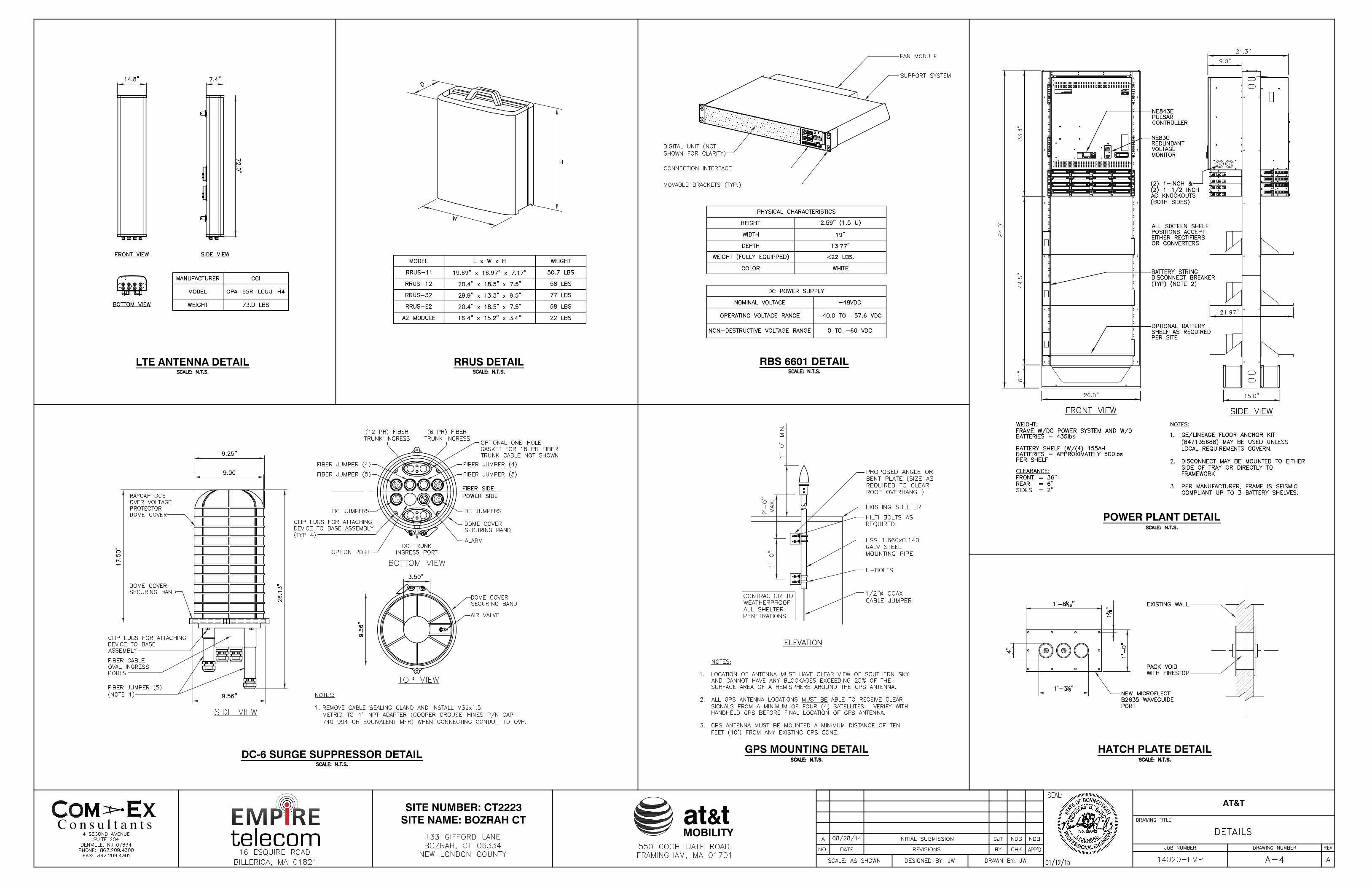
(3) RR90-17-02DP w/ Mount Pipe 193(3) RR90-17-02DP w/ Mount Pipe 193(3) RR90-17-02DP w/ Mount Pipe 193(1) Low Profile Platform 193Lightning Rod 193Empty Mount Pipe 193Empty Mount Pipe 193Empty Mount Pipe 193HPA-65R-BUU-H8 w/ Mount Pipe 182HPA-65R-BUU-H8 w/ Mount Pipe 182OPA-65R-LCUU-H6 w/ Mount Pipe 182OPA-65R-LCUU-H6 w/ Mount Pipe 182OPA-65R-LCUU-H6 w/ Mount Pipe 182(2) LGP21401 182(2) LGP21401 182(2) LGP21401 182(2) RRUS 11 182(2) RRUS 11 182(2) RRUS 11 182RRUS 12 182RRUS 12 182RRUS 12 182RRUS A2 182RRUS A2 182RRUS A2 182RRUS-32 182RRUS-32 182RRUS-32 182RRUS-E2 182RRUS-E2 182RRUS-E2 182(2) LGP21901 182(2) LGP21901 182(2) LGP21901 1821000860 1821000860 1821000860 182DC6-48-60-18-8F 182DC6-48-60-18-8F 182(3) 12.5' T-Frames (Commscope P/N:MTC3615)
182Powerwave 7770 w/ Mount Pipe 182Powerwave 7770 w/ Mount Pipe 182Powerwave 7770 w/ Mount Pipe 182HPA-65R-BUU-H8 w/ Mount Pipe 182(2) 6' Panel w/ Mount Pipe 175(2) 6' Panel w/ Mount Pipe 175(2) 6' Panel w/ Mount Pipe 175(3) T-Frames 175(2) HBXX-6517DS-A2M w/ Mount Pipe 162(2) HBXX-6517DS-A2M w/ Mount Pipe 162(2) HBXX-6517DS-A2M w/ Mount Pipe 162(2) LNX-6514DS-VTM 162(2) LNX-6514DS-VTM 162(2) LNX-6514DS-VTM 1621900 RRH 2x60W 1621900 RRH 2x60W 1621900 RRH 2x60W 162RRH2x60 RRUs 162RRH2x60 RRUs 162RRH2x60 RRUs 162DB-T1-6Z-8AB-0Z 162DB-T1-6Z-8AB-0Z 162(2) FD9R6004/2C-3L 162(2) FD9R6004/2C-3L 162(2) FD9R6004/2C-3L 162(3) T-Frames 162KS24019-L112A 100PC1N0F-0190B-002M 30PC1N0F-0190B-002M 30DESIGNED APPURTENANCE LOADING
TYPE TYPEELEVATION ELEVATION(3) RR90-17-02DP w/ Mount Pipe 193
(3) RR90-17-02DP w/ Mount Pipe 193
(3) RR90-17-02DP w/ Mount Pipe 193
(1) Low Profile Platform 193
Lightning Rod 193
Empty Mount Pipe 193
Empty Mount Pipe 193
Empty Mount Pipe 193
HPA-65R-BUU-H8 w/ Mount Pipe 182
HPA-65R-BUU-H8 w/ Mount Pipe 182
OPA-65R-LCUU-H6 w/ Mount Pipe 182
OPA-65R-LCUU-H6 w/ Mount Pipe 182
OPA-65R-LCUU-H6 w/ Mount Pipe 182
(2) LGP21401 182
(2) LGP21401 182
(2) LGP21401 182
(2) RRUS 11 182
(2) RRUS 11 182
(2) RRUS 11 182
RRUS 12 182
RRUS 12 182
RRUS 12 182
RRUS A2 182
RRUS A2 182
RRUS A2 182
RRUS-32 182
RRUS-32 182
RRUS-32 182
RRUS-E2 182
RRUS-E2 182
RRUS-E2 182
(2) LGP21901 182
(2) LGP21901 182
(2) LGP21901 182
1000860 182
1000860 182
1000860 182
DC6-48-60-18-8F 182
DC6-48-60-18-8F 182
(3) 12.5' T-Frames (Commscope P/N:MTC3615)
182
Powerwave 7770 w/ Mount Pipe 182
Powerwave 7770 w/ Mount Pipe 182
Powerwave 7770 w/ Mount Pipe 182
HPA-65R-BUU-H8 w/ Mount Pipe 182
(2) 6' Panel w/ Mount Pipe 175
(2) 6' Panel w/ Mount Pipe 175
(2) 6' Panel w/ Mount Pipe 175
(3) T-Frames 175
(2) HBXX-6517DS-A2M w/ Mount Pipe 162
(2) HBXX-6517DS-A2M w/ Mount Pipe 162
(2) HBXX-6517DS-A2M w/ Mount Pipe 162
(2) LNX-6514DS-VTM 162
(2) LNX-6514DS-VTM 162
(2) LNX-6514DS-VTM 162
1900 RRH 2x60W 162
1900 RRH 2x60W 162
1900 RRH 2x60W 162
RRH2x60 RRUs 162
RRH2x60 RRUs 162
RRH2x60 RRUs 162
DB-T1-6Z-8AB-0Z 162
DB-T1-6Z-8AB-0Z 162
(2) FD9R6004/2C-3L 162
(2) FD9R6004/2C-3L 162
(2) FD9R6004/2C-3L 162
(3) T-Frames 162
KS24019-L112A 100
PC1N0F-0190B-002M 30
PC1N0F-0190B-002M 30
SYMBOL LISTMARK MARKSIZE SIZE
A Pirod 105244 B L2 1/2x2 1/2x3/16
MATERIAL STRENGTHGRADE GRADEFy FyFu Fu
A572-50 50 ksi 65 ksi A36 36 ksi 58 ksi
TOWER DESIGN NOTES1. Tower is located in New London County, Connecticut.2. Tower designed for a 85 mph basic wind in accordance with the TIA/EIA-222-F Standard.3. Tower is also designed for a 38 mph basic wind with 0.75 in ice. Ice is considered to
increase in thickness with height.4. Deflections are based upon a 50 mph wind.5. TOWER RATING: 88.3%
EBI Consulting environmental | engineering | due diligence
RRRADIO FREQUENCY EMISSIONS ANALYSIS REPORT EVALUATION OF HUMAN EXPOSURE POTENTIAL
TO NON-IONIZING EMISSIONS
AT&T Existing Facility
Site ID: CT2223
Bozrah CT 133 Gifford Lane
Bozrah, CT 06334
December 11, 2014
EBI Project Number: 62146233
Site Compliance Summary
Compliance Status: COMPLIANT
Site total MPE% of FCC general public
allowable limit: 18.09 %
21 B Street . Burlington, MA 01803 . Tel: (781) 273.2500 . Fax: (781) 273.3311
EBI Consulting environmental | engineering | due diligence December 11, 2014
AT&T Mobility – New England Attn: Cameron Syme 550 Cochituate Road Suite 550 – 13&14 Framingham, MA 01701
Emissions Analysis for Site: CT2223 – Bozrah CT
EBI Consulting was directed to analyze the proposed AT&T facility located at 133 Gifford Lane, Bozrah, CT, for the purpose of determining whether the emissions from the Proposed AT&T Antenna Installation located on this property are within specified federal limits.
All information used in this report was analyzed as a percentage of current Maximum Permissible Exposure (% MPE) as listed in the FCC OET Bulletin 65 Edition 97-01and ANSI/IEEE Std C95.1. The FCC regulates Maximum Permissible Exposure in units of microwatts per square centimeter (µW/cm2). The number of µW/cm2 calculated at each sample point is called the power density. The exposure limit for power density varies depending upon the frequencies being utilized. Wireless Carriers and Paging Services use different frequency bands each with different exposure limits, therefore it is necessary to report results and limits in terms of percent MPE rather than power density.
All results were compared to the FCC (Federal Communications Commission) radio frequency exposure rules, 47 CFR 1.1307(b)(1) – (b)(3), to determine compliance with the Maximum Permissible Exposure (MPE) limits for General Population/Uncontrolled environments as defined below.
General population/uncontrolled exposure limits apply to situations in which the general public may be exposed or in which persons who are exposed as a consequence of their employment may not be made fully aware of the potential for exposure or cannot exercise control over their exposure. Therefore, members of the general public would always be considered under this category when exposure is not employment related, for example, in the case of a telecommunications tower that exposes persons in a nearby residential area.
Public exposure to radio frequencies is regulated and enforced in units of microwatts per square centimeter (μW/cm2). The general population exposure limits for the 700 MHz and 800 MHz Bands are 467 μW/cm2 and 567 μW/cm2 respectively. The general population exposure limit for the PCS and AWS bands is 1000 μW/cm2. Because each carrier will be using different frequency bands, and each frequency band has different exposure limits, it is necessary to report percent of MPE rather than power density.
21 B Street . Burlington, MA 01803 . Tel: (781) 273.2500 . Fax: (781) 273.3311
EBI Consulting environmental | engineering | due diligence Occupational/controlled exposure limits apply to situations in which persons are exposed as a consequence of their employment and in which those persons who are exposed have been made fully aware of the potential for exposure and can exercise control over their exposure. Occupational/controlled exposure limits also apply where exposure is of a transient nature as a result of incidental passage through a location where exposure levels may be above general population/uncontrolled limits (see below), as long as the exposed person has been made fully aware of the potential for exposure and can exercise control over his or her exposure by leaving the area or by some other appropriate means.
Additional details can be found in FCC OET 65.
CALCULATIONS
Calculations were done for the proposed AT&T Wireless antenna facility located at 133 Gifford Lane, Bozrah, CT, using the equipment information listed below. All calculations were performed per the specifications under FCC OET 65. Since AT&T is proposing highly focused directional panel antennas, which project most of the emitted energy out toward the horizon, all calculations were performed assuming a lobe representing the maximum gain of the antenna per the antenna manufactures supplied specifications, minus 10 dB, was focused at the base of the tower. For this report the sample point is the top of a 6 foot person standing at the base of the tower.
For all calculations, all equipment was calculated using the following assumptions:
1) 2 GSM channels (850 MHz) were considered for each sector of the proposed installation. These Channels have a transmit power of 30 Watts per Channel.
2) 2 UMTS channels (PCS Band - 1900 MHz) were considered for each sector of the proposed
installation. These Channels have a transmit power of 30 Watts per Channel. 3) 2 UMTS channels (850 MHz) were considered for each sector of the proposed installation.
These Channels have a transmit power of 30 Watts per Channel. 4) 2 LTE channels (WCS Band – 2300 MHz) were considered for each sector of the proposed
installation. These Channels have a transmit power of 30 Watts per Channel. 5) 2 LTE channels (PCS Band – 1900 MHz) were considered for each sector of the proposed
installation. These Channels have a transmit power of 60 Watts per Channel. 6) 2 LTE channel (700 MHz Band) was considered for each sector of the proposed installation.
These Channels have a transmit power of 60 Watts per Channel.
21 B Street . Burlington, MA 01803 . Tel: (781) 273.2500 . Fax: (781) 273.3311
EBI Consulting environmental | engineering | due diligence
7) All radios at the proposed installation were considered to be running at full power and were uncombined in their RF transmissions paths per carrier prescribed configuration. Per FCC OET Bulletin No. 65 - Edition 97-01 recommendations to achieve the maximum anticipated value at each sample point, all power levels emitting from the proposed antenna installation are increased by a factor of 2.56 to account for possible in-phase reflections from the surrounding environment. This is rarely the case, and if so, is never continuous.
8) For the following calculations the sample point was the top of a six foot person standing at
the base of the tower. The maximum gain of the antenna per the antenna manufactures supplied specifications minus 10 dB was used in this direction. This value is a very conservative estimate as gain reductions for these particular antennas are typically much higher in this direction.
9) The antennas used in this modeling are the Powerwave 7770 for 850 MHz and 1900 MHz (PCS) channels and the CCI OPA-65R-LCUU-H8 for 700 MHz, 850 MHz, 1900 MHz and 2300 MHz channels. This is based on feedback from the carrier with regards to anticipated antenna selection. The Powerwave 7770 has a maximum gain of 11.4 dBd for 850 MHz and 13.4 dBd for 1900 MHz at its main lobe. The CCI OPA-65R-LCUU-H8 has a maximum gain of 13.2 dBd for 700 MHz, 14.1 dBd for 850 MHz, 15 dBd for 1900 MHz and 15.6 dBd for 2300 MHz at its main lobe. The maximum gain of the antenna per the antenna manufactures supplied specifications, minus 10 dB, was used for all calculations. This value is a very conservative estimate as gain reductions for these particular antennas are typically much higher in this direction.
10) The antenna mounting height centerlines of the proposed antennas are 182 feet above ground
level (AGL). 11) Emissions values for additional carriers were taken from the Connecticut Siting Council
active database. Values in this database are provided by the individual carriers themselves.
All calculations were done with respect to uncontrolled / general public threshold limits.
21 B Street . Burlington, MA 01803 . Tel: (781) 273.2500 . Fax: (781) 273.3311
EBI Consulting environmental | engineering | due diligence AT&T Site Inventory and Power Data
Sector: A Sector: B Sector: C Antenna #: 1 Antenna #: 1 Antenna #: 1
Make / Model: Powerwave 7770 Make / Model: Powerwave 7770 Make / Model: Powerwave 7770 Gain: 13.4 / 11.4 dBd Gain: 13.4 / 11.4 dBd Gain: 13.4 / 11.4 dBd
21 B Street . Burlington, MA 01803 . Tel: (781) 273.2500 . Fax: (781) 273.3311
EBI Consulting environmental | engineering | due diligence Summary
All calculations performed for this analysis yielded results that were within the allowable limits for general public exposure to RF Emissions.
The anticipated maximum composite contributions from the AT&T facility as well as the site composite emissions value with regards to compliance with FCC’s allowable limits for general public exposure to RF Emissions are shown here:
AT&T Sector Power Density Value (%) Sector 1: 2.21% Sector 2: 2.21 % Sector 3 : 2.21 %
AT&T Total: 6.62 %
Site Total: 18.09 %
Site Compliance Status: COMPLIANT
The anticipated composite MPE value for this site assuming all carriers present is 18.09% of the allowable FCC established general public limit sampled at the ground level. This is based upon values listed in the Connecticut Siting Council database for existing carrier emissions.
FCC guidelines state that if a site is found to be out of compliance (over allowable thresholds), that carriers over a 5% contribution to the composite value will require measures to bring the site into compliance. For this facility, the composite values calculated were well within the allowable 100% threshold standard per the federal government.
Scott Heffernan RF Engineering Director EBI Consulting 21 B Street Burlington, MA 01803
21 B Street . Burlington, MA 01803 . Tel: (781) 273.2500 . Fax: (781) 273.3311