November 14, 2010 Dr. Andrew Rawicz School of Engineering Science Simon Fraser University Burnaby, British Columbia V5A 1S6 Re: ENSC 440 Design Specification for an Automatic Parking Enforcer System Dear Dr. Rawicz, Attached is a document from Park Inc. describing the design specification for the Automatic Parking Enforcer (APE) system. This document outlines how the APE system will meet the various requirements that were specified in the Functional Specification for an Automatic Parking Enforcer System document. APE is a product that captures the license plate image with the use of an infrared camera and converts the image to a series of letters and numbers. The Letters and numbers of each license plate are then matched with an existing database to determine whether the parked vehicle has permission to park in that particular parking lot. This document is designed to provide a higher level understanding of the logic behind the chosen design of the APE system. Hence, this document will be used as a guide by our team of engineers during the proof of principle, design and development phase of the APE system. APE system is produced by Park Inc. which consists of five talented and dedicated members: Rodin Maroufi, Rosy Johal, Amin Moshgabadi, Yi-Chen Kuo, and Shadi Rohani. Please feel free to contact us with any questions or comments that you may have regarding this design specification by phone at 778.865.2444 or by e-mail at [email protected]. Sincerely,
Rodin Maroufi Rodin Maroufi President and CEO Park Inc. Enclosure: Design Specification for an Automatic Parking Enforcer System
This document for the APE system is intended to provide a detailed description of the design for the proof - of - concept and the final product. Thus, the design considerations in respect to the functional requirements marked II and III as specified in the document Functional Specification for An Automatic Parking Enforcer[1] will be discussed.
Section 2 of this document highlights the higher level design of the APE system. Section 3 of this document highlights the design of the general electrical and mechanical requirements of the APE system. Section 4 outlines the design requirements of the Infrared Camera, the USB DVR and the camera bracket. Section 5, 6 and 7 outline the design of the software component of the APE system. Thus, each of those respective sections give a detailed description of: the license plate recognization, the license plate segmentation, and the OCR. Section 9 of this document discusses the design requirements of the GUI. Finally, section 10 outlines the logic behind the design approach taken during system testing.
Hence, this report includes a detailed description of the resources required to implement a successful APE system. Some of these resources include system block diagrams, software flow charts, and images of the GUI.
Figure 1: The Overview of the APE System Design........................................................................2 Figure 2: High level Overview of the APE System..........................................................................3 Figure 3: Guide to Perform a Battery Check..................................................................................4 Figure 4: The Infrared Camera Used in the APE System................................................................5 Figure 5: The USB DVR...................................................................................................................6 Figure 6: Method to Connect the USB DVR to the Camera...........................................................6 Figure 7: Camera Bracket..............................................................................................................7 Figure 8: High Level Block Diagram of the License Plate Recognizer............................................8 Figure 9: High Level Block Diagram of the Skewed Correction Algorithm....................................9 Figure 10:The High Level Block Diagram of the GUI.....................................................................10 Figure 11: Screenshot of the Login Window................................................................................10 Figure 12: Screenshot of the SFU Burnaby Parking Lots Window................................................11 Figure 13: Screenshot of the Main Window.................................................................................12 Figure 14: Logic for the Four Validation Mechanisms..................................................................13 Figure 15: The “Options” Pop Up Window...................................................................................14 Figure 16: “Information Center” Pop Up Window.......................................................................14
List of Tables
Table 1: Camera Specifications.....................................................................................................5 Table 2: USB DVR Specifications...................................................................................................6 Table 3: Camera Bracket Specifications........................................................................................7
Version Date Task 1.0 10 / 11 / 2010 Rough copy completed 1.1 12 / 11 / 2010 Editing completed 1.2 15 / 11 / 2010 Accepted by all team members
Glossary
FPS Frames Per second
TCP Transmission Control Protocol
IP Internet Protocol
APE Automatic Parking Enforcer
OCR Optical Character Reorganization
GUI Graphical User Interface
CSA Canadian Standards Association
ASCII American Standard Code for Information Interchange
SSL Secure Socket Layer
PFSA Parking Federation Standard Association
1
1. Introduction
The APE system from Park Inc. is designed to reduce the amount of workers and time required to patrol parking lots. Thus, a successful APE system will reduce the cost overhead of a company by replacing the traditional way parking lots are patrolled with a more efficient, accurate and environment friendly system. It is initially designed to focus on the SFU Burnaby Campus Parking lots. However, it will later be revised to use in other parking lots and will also branch into some security applications. The initial APE system consists of an infrared camera, and a software program with image processing and a graphical user interface. The infrared Camera will be mounted on a patrolling officer’s vehicle and will be responsible for taking continuous video of the parked vehicles. From this video, images of the parked vehicle will be obtained. The most clear of these images will used to perform image processing. An infrared camera is used to separate the license plate from the rest of the vehicle because the material used in the production of license plates allows them to reflect light. Thus, causing the license plate to be distinct from the rest of the vehicle. When the image processing is complete, the license plate characters obtained will be compared to a database in mySQL to determine whether the vehicle has authorization to be parked in that particular spot. Overall, the final prototype of the APE system will be implemented in the following five parts: license plate segmentation, optical character reorganization (OCR), graphical user interface (GUI), integration of all parts, and testing of the final prototype. Usability and functionality tests of the APE system will commence when the prototype is fully implemented. The completion date of the APE system is still December 6, 2010.
1.1 Scope This document illustrates how the design of the prototype will meet the functional requirements set in the Functional Specification for the Automatic Parking Enforcer System [1] document. Additionally, this document will also be used to illustrate the reasoning behind certain elements and choices in the design of the APE system. Furthermore, this document will serve as an important reference to the Park Inc. Engineering team during the implantation and development of the APE system.
1.2 Intended Audience This document is intended for the whole Park Inc. team, who shall refer to it at various stages of the implementation process. The engineers will use the document to ensure that the product meets the CSA standards as well as other requirements. The engineers will also use this document to verify that the final prototype functions according to the requirements proposed in the document Functional Specification for the Automatic Parking Enforcer System [1].
2
2. System Specification
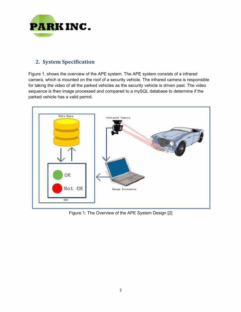
Figure 1, shows the overview of the APE system. The APE system consists of a infrared camera, which is mounted on the roof of a security vehicle. The infrared camera is responsible for taking the video of all the parked vehicles as the security vehicle is driven past. The video sequence is then image processed and compared to a mySQL database to determine if the parked vehicle has a valid permit.
Figure 1: The Overview of the APE System Design [2]
3
3. System Overview
This section provides a high level overview of the APE system, which is shown in Figure 2. Additionally, the general electrical and mechanical requirements will also be discussed in this section. However, a detailed description of the individual components of the APE system will be discussed in their respective sections further in the document.
Figure 2: High Level Overview of the APE System.
The APE system can be separated into five different components such as: the camera, Image processing unit, OCR, database comparison, and the GUI. The infrared camera will be responsible for taking a video sequence of the parked vehicles. From this video sequence the image processing unit will be responsible for obtaining a clear image and localizing the license plate from that image. Once, a license plate is detected the image of the license plate is passed to the OCR for license plate character recognition. The output of the OCR will then be compared to a database of registered vehicles for that particular parking lot. The result of this comparison will be published by the GUI.
4
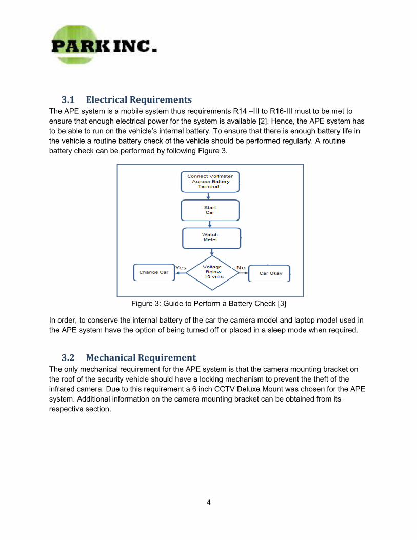
3.1 Electrical Requirements The APE system is a mobile system thus requirements R14 –III to R16-III must to be met to ensure that enough electrical power for the system is available [2]. Hence, the APE system has to be able to run on the vehicle’s internal battery. To ensure that there is enough battery life in the vehicle a routine battery check of the vehicle should be performed regularly. A routine battery check can be performed by following Figure 3.
Figure 3: Guide to Perform a Battery Check [3]
In order, to conserve the internal battery of the car the camera model and laptop model used in the APE system have the option of being turned off or placed in a sleep mode when required.
3.2 Mechanical Requirement The only mechanical requirement for the APE system is that the camera mounting bracket on the roof of the security vehicle should have a locking mechanism to prevent the theft of the infrared camera. Due to this requirement a 6 inch CCTV Deluxe Mount was chosen for the APE system. Additional information on the camera mounting bracket can be obtained from its respective section.
5
4. The Infrared Camera
In this section, the Infrared camera chosen for the APE system will be discussed. We chose the Weatherproof Outdoor Infrared Day Night Color CCD Dome CCTV Surveillance Security Camera to be part of the APE system. Figure 4 shows the images of the camera taking video at different angles.
Figure 4: The Infrared Camera Used in the APE System [4]
This particular model was chosen to be part of the APE system because it met all the functional requirements set for the camera in the Functional Specification for the Automatic Parking Enforcer System document. For example, this camera has a Weatherproof aluminum housing design, which makes this model ideal to operate in rain, fog, snow and indoors. It is also contains 36 built in lights, which enable the model to meet the requirement that the camera be infrared. Additionally, the minimum resolution for this camera is 0 Lux, hence making it a ideal choice for operations with low lighting. The camera also takes images at a high rate,30 frames per second, thus the camera can accommodate a fast moving vehicle [4]. Furthermore, this model can be used for patrolling parking lots inside because it has a built-in IR filter changeable mechanism. This mechanism allows the camera to achieve accurate color representation in varying lighting conditions. Table 1 lists the other features of the camera that make this model the optimal choice for the APE system.
Table 1: Camera Specifications
6
4.1 USB DVR USB DVR Surveillance Camera Video Capture Network 1OZ will be used to synchronize the camera with the users laptop. An image of this USB DVR is shown in Figure 5 and the method to connect the USB DVR to the camera is shown in Figure 6.
Figure 5: The USB DVR [4]
Figure 6: Method to Connect the USB DVR to the Camera
Some specifications that make this USB DVR optimal for the APE system are that it can: connect to any Laptop through USB port, record 30 frames/sec to a Laptop’s hard drive, support schedule recording, record from a frame rate ranging from 1 to 30 fps, and support remote surveillance and PTZ control through a net browser. Table 2 shows other important specifications for the USB DVR.
Table 2: USB DVR Specifications
7
4.2 Camera Bracket The camera bracket chosen to hold the camera for the APE system is a 6 inch CCTV Deluxe Mount, an image of the camera bracket is shown in Figure 7.
Figure 7: Camera Bracket [5]
This particular model was chosen for the APE system because it meets all the requirements specified for the camera bracket in the document Functional Specifications for an Automatic Parking Enforcer System [1]. For example, the camera bracket allows for a ���° rotation and has two adjusting points, which allow for maximum positioning power of the camera bracket. It also has a suction bottom, which causes the camera bracket to achieve a tight grip on the vehicle’s surface and thus enabling the camera to obtain greater image stabilization. Furthermore, this particular camera bracket has a machine aluminum alloy surface, which defends it against rusting and cracking. Furthermore, Table 3 lists additional specifications of the camera bracket.
Table 3: Camera Bracket Specifications
5. Laptop
Any Laptop that meets the following requirements can be used in the APE system. The first requirement is that the laptop has to be able to run on Windows XP or Vista, this requirement must be met because the application for the APE system is a Win 32 application. Thus, it will only be supported by machines running on Vista or XP. The next requirement is that the Processor speed of the laptop has to be 2GHz or more, because the APE system must be able to process if a parked vehicle has a valid permit in one or two seconds. Additionally, the memory of the laptop has to be 2GB or greater and the hard drive has to be 120Gigs.
8
6. License Plate Recognizer
In this section, the License Plate Recognizer portion of the APE system will be discussed. The purpose of the License Plate Recognizer is to recognize only the License Plate from an image of the whole vehicle. Figure 8 provides a high level block diagram of the License Plate Recognizer.
Figure 8: High Level Block Diagram of the License Plate Recognizer
The general principle of the License Plate Recognizer is to take a clear RGB image from the video sequence provided by the camera and convert it into a greyscale image. This greyscale image is then processed by the OPenCV library. The OPenCv Library is a open source vision library developed by IBM. The library contains many easy to use functions to do matrix manipulations on images. The final step in License plate reorganization is to use a morphological edge detection technique to determine where the license plate is located in the image.
Listed below are the detailed steps to recognize a license plate after a image has been converted to greyscale:
1. OPenCv function dilate() is used to make the image a blur and to reduce the noise in the image. 2. OPenCV function erode() is used to make the sharp edges in the dilated image more apparent. 3. Eroded image is then subtracted from the original image to highlight the sharp edges in the
image. 4. A threshold is then applied to reduce the noise in the background
a. This leaves only a few sharp edges in the image. 5. A black and white image is then graphed in a vertical and horizontal histogram
a. This allows the concentration of the edges to be more apparent. b. The license plate is a small area with a lot of sharp edges in both the horizontal and
vertical histograms. 6. Histograms are then ranked by size ranging from biggest to smallest . 7. A region with the ratio of width vs. height closest to 1.72 is chosen.
a. The ratio of the width and the height of a north American license plate is about 1.72
9
7. License Plate Segmentation
In this section, the License Plate Segmentation portion of the APE system will be discussed. The purpose of License Plate Segmentation is to segment the License Plate once it has been identified from an image of the whole vehicle.
The general principle of License Plate Segmentation is to crop the recognized license plate from the rest of the image. If the image of the license plate is not aligned properly then a Skew Correction Algorithm, which finds the angle at which the image is skewed, is applied to align the image by deskewing the particular angle by using a affine transformation [6]. Figure 9 shows a high level block diagram of the Skewed Correction Algorithm.
Figure 9: High Level Block Diagram of the Skewed Correction Algorithm.
8. OCR (Optical Character Recognization )
In this section, the OCR portion of the APE system will be discussed. The purpose of the OCR is to read the License plate characters from the segmented image. A open source software called Tesseract will be used as the OCR engine for the APE system. Tesseract will be used because it was chosen as one of the top 3 engines in the UNLV Accuracy test [7].
The detailed steps for the OCR are shown below:
• After the cropped image is deskewed, it will once again be filtered to minimize noise and make the letters in the license plate stand out.
• The image is then passed to the engine and the engine will return a text file containing the license plate number.
• If the numbers are missing or they don’t match the standard, The image is ignored and another image is taken.
10
9. GUI (Graphical User Interface)
The purpose of the GUI is to display the output of the APE system in a user friendly environment. The GUI is designed in Visual C++ , because it allows for an easier integration with the rest of the program. The user interface is a multilayered application and the high level block diagram for the interface is shown in Figure 10. There are three main layers to the program: the login window, map of SFU Burnaby Campus window, and the main window.
Figure 10:The High Level Block Diagram of the GUI
A login window was deemed necessary to block non- security personnel from accessing the application and modifying the database of allowed vehicles and personnel. Thus, when the application is started, the login window is the first window to run. The screen cap of the login window is shown in Figure 11. In this window, the user needs to enter a valid username and password, every patrol officer will be given a username and password to access the application. Once, the username and password are entered they will be compared to a database in mySQL, which will be updated regularly to compensate for old employees leaving and new employees being hired. Once, the users credentials have been verified, they will be directed to a window with the map of the various SFU Burnaby campus parking lots.
Figure 11: Screenshot of the Login Window
11
Figure 12 shows the screenshot for the window with the map of the various SFU Burnaby parking lots. The user will click the appropriate parking lot that they will be patrolling. The four SFU Burnaby parking lots to monitored for the prototype are: B,C, D and E [8]. When a specific parking lot is pressed, the program will enter the appropriate table in the mySQL database, the table will have all the vehicles allowed in that particular parking lot. The database also allows for multiple vehicles to be registered under one particular permit. Once a appropriate parking lot is clicked the user will be directed to the main window.
Figure 12: Screenshot of the SFU Burnaby Parking Lots Window
12
The main window is responsible for displaying the final output of the program. Figure 13, shows the screenshot of the main window, which contains all the elements specified in the functional requirements R35-II to R42-II. Hence, the main window has a display for: the real time video, the image of the license plate taken by the camera, the section of the database where the license plate is stored, a validation check , a button to go back to the window with various SFU Burnaby Parking Lots, a button to Log off, and a manual search option.
Figure 13: Screenshot of the Main Window
It was deemed necessary to include a manual search option because weather conditions or other obstructions can prevent the camera from taking a clear image of the license plate. Hence, with the manual search option the user can enter the license plate number manually and search the database to see if a valid permit exists for the vehicle. The validation box either displays a check sign, if the parked vehicle has the necessary permit or a x sign, if the parked vehicle does not have the necessary permit. Additionally, a sound will also be played to alert the user if a vehicle does not have a necessary permit. The sound was added to prevent the user from having to look at the display to see if the vehicle had the necessary permit while driving.
13
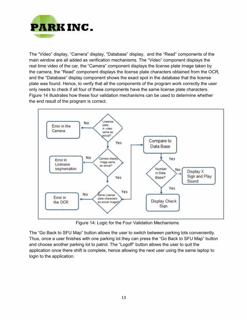
The “Video” display, “Camera” display, “Database” display, and the “Read” components of the main window are all added as verification mechanisms. The “Video” component displays the real time video of the car, the “Camera” component displays the license plate image taken by the camera, the “Read” component displays the license plate characters obtained from the OCR, and the “Database” display component shows the exact spot in the database that the license plate was found. Hence, to verify that all the components of the program work correctly the user only needs to check if all four of these components have the same license plate characters. Figure 14 illustrates how these four validation mechanisms can be used to determine whether the end result of the program is correct.
Figure 14: Logic for the Four Validation Mechanisms
The “Go Back to SFU Map” button allows the user to switch between parking lots conveniently. Thus, once a user finishes with one parking lot they can press the “Go Back to SFU Map” button and choose another parking lot to patrol. The “Logoff” button allows the user to quit the application once there shift is complete, hence allowing the next user using the same laptop to login to the application.
14
The main window also contains a menu bar consisting of a “Tools” menu and a “Information Center” menu. The “Tools” menu consists of a pop up window called “Options”, which allows the user to determine whether he/she will like a sound played if a violation occurred and it also allows the user to determine what type of alert they would like played. Figure 15 shows the screen shot of the “Options” pop up window.
Figure 15: The “Options” Pop Up Window
The “Information Center” contains relevant contact information for the parking personnel, such as the contact information for Parking Services Manager and etc. The “Information Center” pop up window can be seen in Figure 16.
Figure 16: “Information Center” Pop Up Window
15
10. System Testing
The purpose of system testing is to successfully implement the requirements stated in the document Functional Specifications for an Automatic Parking Enforcer System [1]. Thus, to ensure that the prototype functions properly, it will be tested during and after each stage of the design process.
10.1 Camera Testing The camera will go through initial testing to see whether the motor is fast enough to continuously take pictures while the security vehicle travels at a fast speed. Hence, a test plan for the camera is to mount it on a vehicle and drive the vehicle at an appropriate speed in the parking lot. If the camera takes clear images with a one second difference between each image then the camera will pass the test. However, there are some additional tests that the camera also needs to pass such as:
• Taking sufficient number of pictures to analyze. • Taking clear shots of the license plate. • Able to transfer the images taken to a local computer. • Able to save the image on the computer.
10.2 License Plate Segmentation Testing License plate segmentation is an important component of the APE system. It consists of finding the exact spot the license plate is located on the image. To check whether our program is working properly the system must provide the correct output 95 percent of the time.
Testing the License Plate Segmentation code, will incorporate unit tests, functional tests and integration tests. The unit tests will be performed to ensure that each part of the code operates properly and independently. The functional tests will be performed after all the unit tests are passed. Functional tests will be used to verify that all the individual processes function correctly. Once, all the functional tests are passed then integration tests will be performed to ensure that all the code functions and communicates correctly. Therefore, if the program successfully crops the license plate from the remaining image then the Letter segmentation testing will be considered a success.
16
10.3 OCR Testing The OCR engine will be tested by comparing the actual license plate number to the ASCII characters outputted by the OCR. If the two are the same 95 percent of the time, then the OCR will be confirmed to function properly.
10.4 User Interface and Data Connection Testing To test the connection between the user interface and database, license plates of vehicles which are known to have valid permits will be manually inserted in the search option of the GUI and the database section of the GUI is observed. If the license plate inserted manually is the same as the license plate found in the database section 100 percent of the time then the connection will be deemed a success.
10.5 GUI Testing The security features of the GUI can be tested by verifying that only employee’s with valid passwords and id’s can access the database. Furthermore, each password will require at least 7 characters which include numbers and letters. Additionally, the security of the database consisting of the valid login id’s will also be tested to verify that unauthorized access and to secure SFU drivers’ information will not occur.
The usability of the GUI will be tested by setting up test groups to ensure that the GUI is user friendly. Vis-a-vis, the layout is well-constructed, all notify messages are clear and informative, and buttons are properly functioning. A example of a GUI test, is to set up a test user and see if he or she had any trouble navigating through the program.
10.6 Final Prototype Testing The final prototype testing will consist of the following procedures:
• Mount the camera on a roof of a car • Connect the camera and the USB DVR • Connect the USB DVR to the Laptop in the car • Run the APE application on the Laptop • Turn on the camera • Start driving the car
If the correct answer is obtained 95 percent of the time , then the APE system will be considered a success.
17
11. Conclusion
This document describes the design required to achieve the functional, operational and safety requirements which need to be met if a successful APE system is to be produced. We are currently in the process of designing, testing and implementing the prototype, which will meet all the requirements needed to be successful. The target date for the prototype completion is still December 6, 2010.
18
12. References
[1] Park Inc, “Project Proposal of an Automatic Parking Enforcer System”
[2] Park Inc, “Functional Requirements of an Automatic Parking Enforcer System”
[3] Chemelec. “Testing Alternators and Car Batteries”, 2005. [Online]. Available: http://www3.telus.net/chemelec/Projects/Alternator/Alternator.htm [Accessed: Nov. 12, 2010].
[4] “Outdoor Dome Security Camera weatherproof Day Night bdz” , 2010. [Online]. Available: http://cgi.ebay.com/Outdoor-Dome-Security-Camera-weatherproof-Day-Night-bdz-/120624969098 [Accessed: Oct. 10, 2010].
[5] “CCTV Security Camera Mounts and Brackets” , 2010. [Online]. Available : http://nservices.com/mounts.htm [Accessed: Oct. 10, 2010].
[6] Martinsky, Ondrej. “Brno University of Technology” , 2007. [Online]. Available: http://indrasaifudin.files.wordpress.com/2009/10/anpr.pdf[Accessed: Sept. 16, 2010].