1/26 4/2 and 4/3 directional valves, pilot operated Type H-4WEH…XE Sizes 10, 16, 25, 32 Component series 4X, 6X, 7X Maximum operating pressure Size 10 315 bar Size 16, 25, 32 350 bar Maximum flow 1100 l/min RE 24751-XE-B2/01.10 Replaces: 04.07 H7097 ATEX units For explosive areas Part II Technical data sheet What you need to know about these operating instructions These operating instructions apply to the explosion-proof version of Rexroth valves and consist of the following three parts: Part I General information RE 07010-X-B1 Part II Technical data sheet RE 24751-XE-B2 Part III Product-specific instructions RE 24751-XE-B3 You can find further information on the correct handling of Rexroth hydraulic products in our publication “General product information on hydraulic products” RE 07008. RE 24751-XE-B0 Information on explosion protection: Range of application in accordance with the Explosion Protec- tion Directive and type of protection – Range of application as per Directive 94/9/EC II2G – Type of protection of valve solenoid EEx em IIT4 according to EN 60079-7:2007 / EN 60079-18:2005 Special features of seawater-resistant valves – The external metal parts are galvanized or treated with anti- corrosion agent. – The limited seawater resistance is defined by “SO329” in the ordering code.
What you need to know about these operating instructions
These operating instructions apply to the explosion-proof version of Rexroth valves and consist of the following three parts:Part I General information RE 07010-X-B1Part II Technical data sheet RE 24751-XE-B2Part III Product-specific instructions RE 24751-XE-B3You can find further information on the correct handling of Rexroth hydraulic products in our publication “General product information on hydraulic products” RE 07008.
RE 24751-XE-B0
Information on explosion protection:Range of application in accordance with the Explosion Protec-tion Directive and type of protection – Range of application as per Directive 94/9/EC II2G– Type of protection of valve solenoid EEx em IIT4 according
to EN 60079-7:2007 / EN 60079-18:2005Special features of seawater-resistant valves– The external metal parts are galvanized or treated with anti-
corrosion agent.– The limited seawater resistance is defined by “SO329” in the
ordering code.
2/26 Bosch Rexroth AG Hydraulics H-4WEH…XE RE 24751-XE-B2
Table of contents
Features
– Valve for controlling start, stop and direction of a flow, for proper use in explosive areas
– Electrohydraulic actuation (WEH)– For subplate mounting, porting pattern according to
DIN 24340-A and ISO 4401, subplates available in FE/ZN version (see pages 21 to 24)
– Spring centering, spring end position or hydraulic end position– Wet-pin DC or AC voltage solenoids, with detachable
valve solenoid– Manual override, optional– Electrical connection as individual connection with cable
gland (see page 14)– Switching time adjustment, optional– Preload valve in channel P of the main valve, optional
Content PageFeatures 2Function, section 3Ordering code and scope of delivery 4…5Spool symbols 6…9Pilot oil supply 9Technical data 10…13Electrical connection 14…15Characteristic curves, performance limits 16…19Switching time adjustment, pressure reducing valve, preload valve 20Unit dimensions 21…25
Directional valves type H-4WEH...The valve type H-4WEH is a directional spool valve with elec-trohydraulic actuation. It controls the start, stop and direction of a flow.The directional valve basically comprises of the main valve with housing (1), the main control spool (2), one or two return springs (3.1) and (3.2) as well as the pilot control valve (4) with one or two solenoids “a” (5.1) and/or “b” (5.2).The main control spool (2) in the main valve is held in the zero or initial position by the springs or by means of pressur-ization. In the initial position, the two spring chambers (6) and (8) are, via the pilot control valve (4), connected to the tank in a pressureless form. Via the pilot line (7), the pilot control valve is supplied with pilot oil. The supply can be implement-ed internally or externally (externally via port X).Upon actuation of the pilot control valve, e.g. solenoid “a”, the pilot control spool (10) is moved to the left and thus, the pilot pressure is applied to the spring chamber (8). The spring chamber (6) remains unpressurized.
The pilot pressure acts on the left side of the main control spool (2) and pushes it against the spring (3.1). In the main valve, ports P and A are thus connected with B and T respectivelyUpon shut-off of the solenoid, the pilot control spool returns into the initial position (except for impulse spool). The spring chamber (8) is unloaded to the tank.Via the pilot control valve, the pilot oil from the spring cham-ber is displaced into channel Y.The pilot oil supply and return can be implemented internally or externally.An optional manual override (9) allows control spool (10) to be moved without energization of the solenoid.
Function, section
Type H-4WEH 16…XE
5.2 10 4 5.1
9
T
„b“ „a“
7
6
3.1
1
2
3.2
8
AP
BX Y
4/26 Bosch Rexroth AG Hydraulics H-4WEH…XE RE 24751-XE-B2
Ordering code and scope of delivery
Up to 315 bar – size 10Up to 350 bar – size 16, 25, 32 = H4-way version = 4Directional valve, electrohydraulic actuation = WEHSizeSize 10 = 10Size 16 = 16Size 25 = 25Size 32 = 32Spool return main valveBy springs = no codeHydraulic 1) = HSpool symbols see page 6Component series 40 to 49 – size 10 = 4X(40 to 49: unchanged installation and connection dimensions)Component series 60 to 69 – size 25 (4W.H 25.) and size 32 = 6X(60 to 69: unchanged installation and connection dimensions)Component series 70 to 79 – size 16 = 7X(70 to 79: unchanged installation and connection dimensions)Spool return in the pilot control valve with 2 spool positions and 2 solenoids only possible with spools C, D, K, Z and hydraulic spool return in the main valve:Without spring return = OWithout spring return with detent = OFPilot control valve with wet-pin solenoids, High-power valve (RE 23178-XE-B2) = 6E DC voltage 24 V = G24AC voltage 230 V 50/60 Hz = W230RFor more voltages and frequencies, see page 15Without manual override = no codeWith manual override (standard) = N Explosion protection “Increased safety” = XEFor details see information on the explosion protection, page 11External pilot oil supply, external pilot oil return = no codeInternal pilot oil supply, external pilot oil return 2) = EInternal pilot oil supply, internal pilot oil return 2) = ETExternal pilot oil supply, internal pilot oil return = T
H 4 WEH 6E XE
Included in the delivery:Valve operating instructions with declaration of conformity in part III
no code = NBR seals V = FKM seals (other seals at request) Note
Observe compatibility of seals with the hydraulic fluids used!no code = Without pressure reducing valveD3 = With pressure reducing valve
Preload valve (not for size 10)no code = Without preload valveP4,5 = With preload valve (pö = 4.5 bar)
Throttle insert no code = Without throttle insertB08 = Throttle Ø 0.8 mmB10 = Throttle Ø 1.0 mmB12 = Throttle Ø 1.2 mmB15 = Throttle Ø 1.5 mm
Electrical connectionZ2 = Solenoid with terminal box and cable gland
For details see chapter electrical connection no code = Without switching time adjustmentS = Switching time adjustment as supply controlS2 = Switching time adjustment as discharge control
1) 2 spool positions (hydraulic end position): Only spools C, D, K, Z, Y2) With internal pilot oil supply (version E and ET):
• Minimum pilot pressure: Please observe page 10! • In order to avoid inadmissibly high pressure peaks, a throttle insert (B10) must be provided in port P of
the pilot control valve (see page 9).
Ordering code and scope of delivery
6/26 Bosch Rexroth AG Hydraulics H-4WEH…XE RE 24751-XE-B2
A B
P T
a ba b ../..
A B
P T
a ba b ..H../..
A B
P T
a ba b ..H../O
A B
P T
a ba b ..H../OF
= C
= D
= K
= Z
A B
P T
a ba b ../..
= Y
A B
P T
a ba b ..H../..
A B
P T
a 0a bb
A B
P T
a 0a .A 1)
A B
P T
0 bb .B
= E 1)
= G
= F
= J
= M
= P
= T
= S 2)
= U
= V
= Q
= W
= H
= L
= R
= E19
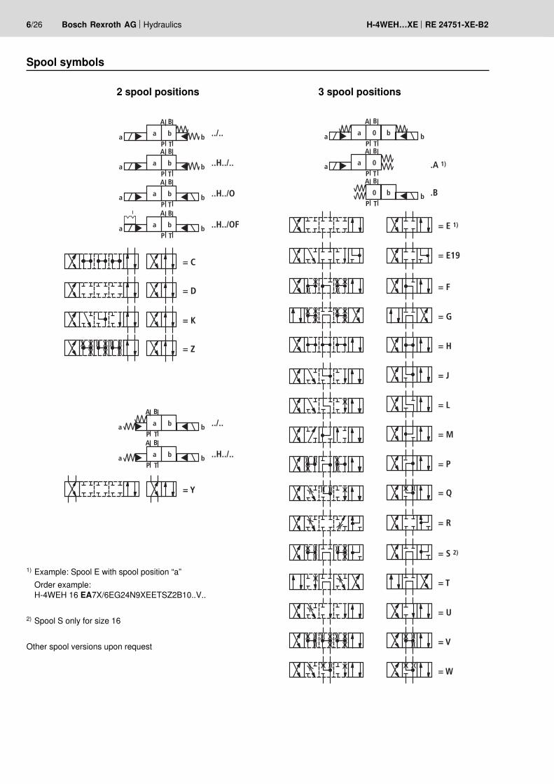
Spool symbols
2 spool positions 3 spool positions
1) Example: Spool E with spool position “a” Order example:
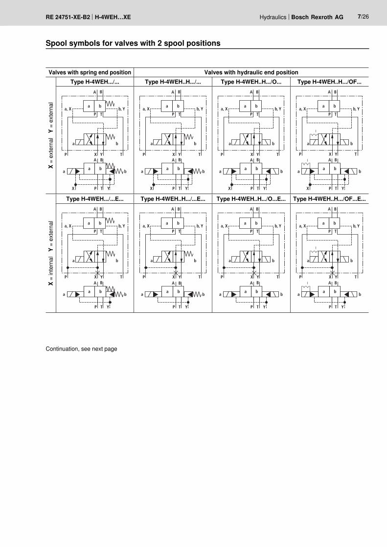
Type H-4WEH…The pilot oil supply is implemented externally via channel X from a separate circuit.The pilot oil return is implemented externally via channel Y into the tank.Type H-4WEH…E…The pilot oil supply is implemented internally from channel P of the main valve. The pilot oil return is implemented externally via channel Y into the tank. In the subplate, port X is closed.Type H-4WEH…ET…The pilot oil supply is implemented internally from channel P of the main valve.The pilot oil return is implemented internally via channel T into the tank. In the subplate, ports X and X are closed.Type H-4WEH…T…The pilot oil supply is implemented externally via channel X from a separate circuit.The pilot oil return is implemented internally via channel T into the tank. In the subplate, port Y is closed.
Pilot oil supplyThrottle insertA valve with throttle insert has to be ordered if the supply vol-ume (pilot oil supply) in channel P of the pilot control valve is to be limited.The throttle insert is inserted in port P of the pilot control valve.
P Seal ring
10/26 Bosch Rexroth AG Hydraulics H-4WEH…XE RE 24751-XE-B2
Technical datageneralInstallation position Any; horizontal with valves with hydraulic spool return “H”
and spools C, D, K, Z or YAmbient temperature range °C –20 … +80 Storage temperature range °C –20 … +70Sizes Size 10 16 25 32Weight Valve with one solenoid kg 7.3 9.4 18.5 41.4
Valve with two solenoids, spring-centered kg 8.2 10.7 19.8 42.8Switching time adjustment kg 0.8Pressure reducing valve kg 0.4
Surface protection Valve body Standard Coating, layer thickness max. 100 µmSO329 Galvanized or phosphatized
Solenoid Galvanized and passivated olive-green (FeZn8D)
Ports P, A, B bar 315 350 350 350Port T with pilot oil return Y external bar 250 250 250 250
with pilot oil return Y internal bar 210Port Y with pilot oil return external bar 210
Flow of the main valve l/min up to 160 up to 300 up to 650 up to 1100Maximum pilot pressure bar 250 (in case of a higher pilot pressure, the use of a pressure
reducing valve is required)Minimum pilot pressure– with pilot oil supply X external or internal
(spools D, K, E, E19, J, L, M, Q, R, U, W)3-spool position valve, spring-centered bar 10 14 13 8.52-spool position valve, spring end position bar 10 14 13 102-spool position valve, hydraulic end position bar 7 14 8 5
– with pilot oil supply internal(spools C, F, H, P, T, V, Z, S 1) ) bar 6.5 2) 4.5 3) 4.5 3) 4.5 3)
Pilot volume for switching process3-spool position valve, spring-centered cm3 2.04 5.72 14.2 29.42-spool position valve cm3 4.08 11.45 28.4 58.8
Pilot volume for shortest switching time l/min approx. 35 approx. 35 approx. 35 approx. 45Hydraulic fluid Mineral oil (HL, HLP) according to DIN 51524 4), fast bio-
degradable hydraulic fluids according to VDMA 24568 (also see RE 90221); HETG (rape seed oil) 4), HEPG (polygly-cols) 5); HEES (synthetic esters) 5), flame-resistant hydraulic fluid HFC according to ISO 12922 6), other hydraulic fluids upon request Ignition temperature > 180 °C
electricalVoltage type Direct voltage Alternating voltageAvailable voltages V 24, 48, 96, 110 110, 230Voltage tolerance (nominal voltage) % ±10Admissible residual ripple % < 5 –Duty cycle/operating mode according to VDE 0580 S1 (continuous operation)Switching time according to ISO 6403 See pages 12 and 13Switching frequency 1/h up to 15000 up to 7200Nominal power at ambient temperature 20 °C W 17Maximum power with 1.1 x nominal voltage and ambient temperature 20 °C W 20.6Protection class according to EN 60529:1991+A1:2000 IP 66 with correctly installed connection line
Technical data
Information on explosion protectionRange of application as per directive 94/9/EC II 2 GType of protection valve c (EN 13463-5:2004)Maximum surface temperature 8) °C 125Temperature class T4Type of protection valve solenoid according to EN 60079-7:2007 / EN 60079-18:2005 EEx em IIT4Type examination certificate Solenoid KEMA 02 ATEX 2240Special conditions for safe useAmbient temperature range °C –20 … +80
1) Spool S only for size 162) For spools C, F, G, H, P, T, V, Z, an internal pilot oil return
without preload valve is only possible if the flow from P → T in the central position (with 3-spool position valve) or when crossing the central position (with 2-spool position valve) is so large that the pressure differential from P → T reaches a value of at least 6.5 bar.
3) For spools C, F, G, H, P, T, V, Z, S 1) – by means of pre-load valve (not size 10) or correspondingly high flow
4) Suitable for NBR and FKM seals5) Suitable only for FKM seals
6) Only in connection with NBR seals, max. admissible pressure 210 bar, ∆p < 15 bar, hydraulic fluid temperature max. 60 °CFor more information, please ask our sales staff.
7) The cleanliness classes specified for the components must be adhered to in hydraulic systems. Effective filtration pre-vents faults and at the same time increases the service life of the components.
For selecting the filters, see technical data sheets: RE 50070, RE 50076 and RE 50081.
8) Due to the temperatures occurring at the surfaces of the valve solenoids, the European standards ISO 13732-1 and EN 982 need to be adhered to! (contact protection)
hydraulic (continued)Hydraulic fluid temperature range °C –30 ... +80 (NBR seals)
–15 ... +80 (FKM seals)Viscosity range mm2/s 2.8 … 500 Maximum permitted degree of contamination of the hydraulic fluid - cleanliness class according to ISO 4406 (c) Class 20/18/15 7)
12/26 Bosch Rexroth AG Hydraulics H-4WEH…XE RE 24751-XE-B2
Switching times – size 10 Pilot pressure bar 70 140 210 250Solenoid voltage type 1) ~ = ~ = ~ = ~ =Switching timeon: Zero position → Spool position
3-spool position valve ms 90 75 85 70 80 65 75 602-spool position valve ms 95 90 90 85 85 80 80 75
off: Spool position → Zero position3-spool position valve ms 40 30 40 30 40 30 40 302-spool position valve ms 45 40 40 35 35 30 30 25
Switching times – size 16Pilot pressure bar 70 140 210 250Solenoid voltage type 1) ~ = ~ = ~ = ~ =Switching timeon: Zero position → Spool position
3-spool position valve, spring-centered ms 90 75 90 70 90 70 85 702-spool position valve ms 95 90 95 85 95 85 90 80
off: Spool position → Zero position3-spool position valve, spring-centered ms 45...60 45 45...60 45 40...55 40 40...45 352-spool position valve ms 45...60 45 45...60 45 40...55 40 40...55 35
Switching times – size 25 Pilot pressure bar 70 140 210 250Solenoid voltage type 1) ~ = ~ = ~ = ~ =Switching timeon: Zero position → Spool position
3-spool position valve, spring-centered ms 110 95 100 85 95 80 90 752-spool position valve ms 180 170 160 140 145 130 130 115
off: Spool position → Zero position3-spool position valve, spring-centered ms 50...65 40 50...65 40 50...65 40 50...65 402-spool position valve ms 45...60 45 45...60 45 40...55 40 40...55 35
1) “~” means AC voltage supply (DC voltage solenoid with integrated rectifier), identification “W” in the ordering code “=” means DC voltage supply, identification “G” in the ordering code
Technical data
Switching times according to ISO 6403Switching time “on”
Period from the switch on of the electric actuation of the solenoid to the pressure change of 5 % in the main valve
Switching time “off”
Period from the switch-off of the electric actuation of the solenoid to the pressure change of 5 % in the main valve
Switching times – size 32 Pilot pressure bar 70 140 210Solenoid voltage type 1) ~ = ~ = ~ =Switching timeon: Zero position → Spool position
3-spool position valve, spring-centered ms 125 90 110 100 95 1152-spool position valve ms 160 140 135 110 120 125
off: Spool position → Zero position3-spool position valve, spring-centered ms 70...85 50 70...85 50 70...85 502-spool position valve ms 125...140 90 95...110 70 75...90 65
Technical data
Free flow cross-section in zero position with spools Q, V and WSpool Q A – T, B – T mm2 13 32 78 83 78Spool V A – T, B – T mm2 13 32 73 83 73
P – A, P – B mm2 13 32 84 83 84Spool W A – T, B – T mm2 2.4 6 10 14 20
1) “~” means AC voltage supply (DC voltage solenoid with integrated rectifier), identification “W” in the ordering code “=” means DC voltage supply, identification “G” in the ordering code
14/26 Bosch Rexroth AG Hydraulics H-4WEH…XE RE 24751-XE-B2
Electrical connectionThe type-tested valve solenoid of the valve is equipped with a terminal box and a type-tested cable gland.
Properties of the terminals and mounting elementsPosition Function Connectable line cross-section Tightening torque
NoteWhen establishing the electrical connection, the protective earthing conductor (PE ) has to be connected properly.
Cable glandType approval EEx e II / II2GThreaded connection M20 x 1.5Thread length mm 5 … 12Temperature range °C –20 … +120Protection class according to EN 60529:1991+A1:2000 IP66, IP67 or IP68Line diameter mm 9 … 11Sealing Outer sheath sealing
Connection lineLine type Non-armored cables and lines (outer sheath sealing)Temperature range °C –20 … > +120
The connection is insensitive to polarity.Solenoids for connection to AC voltage are equipped with an integrated rectifier.
Direct voltage, insensitive to polarity Alternating voltage
+(–)
– (+)
Overcurrent fuse and cut-off voltage peak
NoteA fuse appropriate for the solenoid's rated current (max. 3 x Inom according to DIN 41571 or IEC 60127) or a motor protec-tion switch with short-circuit and thermal instantaneous trip-ping must be connected to each valve solenoid as short-cir-cuit protection. The cut-off capacity of this fuse must match or exceed the short-circuit current of the supply source. This fuse or motor protection switch may only be fitted outside the explosive area or must be of an explosion-proof design.
When inductivities are switched off, voltage peaks result which may cause failures in the connected control electron-ics. For this reason, the valve solenoids comprise an interfer-ence protection circuit which dampens this voltage peak to the value shown in the table.
Voltage data in the valve type code
Nominal voltage valve solenoid
Rated current valve solenoid
Recommended pre-fuse charac-teristics medium
time-lag according to DIN 41571
Maximum voltage value upon switch-off
Interference pro-tection circuit
G24 24 V DC 0.708 A DC 1.25 A –90 V
Suppressor diode bi-directional
G48 48 V DC 0.354 A DC 630 mA –200 V
G96 96 V DC 0.177 A DC 315 mA –370 V
G110 110 V DC 0.155 A DC 315 mA –390 V
W110R 110 V AC 0.163 A AC 315 mA –3 V Bridge rectifier and suppressor diodeW230R 230 V AC 0.078 A AC 160 mA –3 V
16/26 Bosch Rexroth AG Hydraulics H-4WEH…XE RE 24751-XE-B2
Characteristic curves: Type H-4WEH 10...(measured with HLP46 , ϑoil = 40 °C ± 5 °C)
Δp-qV characteristic curves
Flow in l/min →
Pres
sure
diff
eren
tial in
bar
→
Characteristic curve selectionSpool Spool position Spool Zero position
P – A P – B A – T B – T A – T B – T P – TE, Y, D 2 2 4 5F 1 4 1 4 F 3 – 6G, T 4 2 2 6 G, T – – 7H, C 4 4 1 4 H 1 3 5J, K 1 2 1 3L 2 3 1 4 L 3 – –M 4 4 3 4P 4 1 3 4 P – 7 5Q, V, W, Z 2 2 3 5R 2 2 3 –U 3 3 3 4 U – 4 –
Performance limits: Type H-4WEH 10... (measured with HLP46, ϑoil = 40 °C ± 5 °C)
NoteThe specified switching power limits are valid for operation with two directions of flow (e.g. P → A and simultaneous re-turn flow from B → T).Due to the flow forces acting within the valves, the permis-sible switching power limits may be considerably lower with only one direction of flow (e.g. P → A while port B is blocked)!(In such cases, please consult us!)The switching power limit was established while the so-lenoids were at operating temperature, at 10 % undervolt-age and without tank pre-loading.
2- and 3-spool position valvesMaximum flow qV in l/minSpool Operating pressure pmax in bar
200 250 315E, J, L, M, Q, R, U, V, W, C, D, K, Z, Y
Characteristic curves: Type H-4WEH 16...(measured with HLP46 , ϑoil = 40 °C ± 5 °C)
Characteristic curve selectionSpool Spool position
P – A P – B A – T B – T P – TE, Y, D 1 1 3 4 –E19 – 6 8 7 –F 1 1 5 4 –G, T 4 1 5 5 9H, C, Q, V, Z 1 1 5 6 –J, K, L 1 1 5 6 –
Spool Spool positionP – A P – B A – T B – T P – T
M, W 1 1 3 4 –R 1 1 3 – –U 2 2 3 5 –S 3 3 3 – 10
Performance limits: Type H-4WEH 16... (measured with HLP46, ϑoil = 40 °C ± 5 °C)
Δp-qV characteristic curves
Flow in l/min →
Pres
sure
diff
eren
tial in
bar
→
2-spool position valvesMaximum flows qV in l/minSpool Operating pressure pmax in bar
70 140 210 280 350X external, spring end position in the main valve (with pSt min =12 bar)C, D, K, Y, Z 300 300 300 300 300X external, spring end position in the main valve 1)
C 300 300 300 300 300D, Y 300 270 260 250 230K 300 250 240 230 210Z 300 260 190 180 160X external, hydraulic end position in the main valveHC, HD, HK, HZ, HY
300 300 300 300 300
3-spool position valvesMaximum flows qV in l/minSpool Operating pressure pmax in bar
70 140 210 280 350X external, spring centering in the main valve E, E19, H, J, L, M, Q, U, W, R
Note1) If the specified flow values are exceeded, the function of
the return spring is not guaranteed any more in case of pilot pressure failure!
• With pilot oil supply X internal, you must always use a preload valve due to the negative overlap of spools F, G, H, P, T, S, C and HC.
• With spools V, Z and HZ, the preload valve is not neces-sary with flows > 180 l/min.
NoteAlso refer to “Note” page 16
0
2
4
6
8
10
12
14
16
18
20
22
24
26
28
0 50 100 150 200 250 300
8
7
65
4321
10
9
18/26 Bosch Rexroth AG Hydraulics H-4WEH…XE RE 24751-XE-B2
1
2
3
4
56
10
8
6
4
2
00 100 200 300 400
12
14
500
78
600 650
Characteristic curves: Type H-4WEH 25...(measured with HLP46 , ϑoil = 40 °C ± 5 °C)
Performance limits: Type H-4WEH 25... (measured with HLP46, ϑoil = 40 °C ± 5 °C)
Δp-qV characteristic curves
Flow in l/min →
Pres
sure
diff
eren
tial in
bar
→
7 Spool G Central position P – T
8 Spool T Central position P – T
2-spool position valvesMaximum flows qV in l/minSpool Operating pressure pmax in bar
70 140 210 280 350X external, spring end position in the main valve (with pSt min =13 bar)C, D, K, Y, Z 700 700 700 700 650X external, spring end position in the main valve 1)
C 700 700 700 700 650D, Y 700 650 400 350 300K 700 650 420 370 320Z 700 700 650 480 400X external, hydraulic end position in the main valveHC, HD, HK, HZ, HY
700 700 700 700 700
HC../O..HD../O..HK../O..HZ../O..
700 700 700 700 700
HC../OF..HD../OF..HK../OF..HZ../OF..
700 700 700 700 700
3-spool position valvesMaximum flows qV in l/minSpool Operating pressure pmax in bar
70 140 210 280 350X external, spring centering in the main valve E, L, M, Q, U, W,
Characteristic curves: Type H-4WEH 32...(measured with HLP46 , ϑoil = 40 °C ± 5 °C)
Performance limits: Type H-4WEH 32... (measured with HLP46, ϑoil = 40 °C ± 5 °C)
Flow in l/min →
Pres
sure
diff
eren
tial in
bar
→
Δp-qV characteristic curves – spools G and T
Flow in l/min →
Pres
sure
diff
eren
tial in
bar
→
∆p-qV characteristic curves- all other spools
1) Only with spool R2) Not with spool R
2-spool position valvesMaximum flows qV in l/minSpool Operating pressure pmax in bar
70 140 210 280 350X external, spring end position in the main valve (with pSt min =10 bar)C, D, K, Y, Z 1100 1040 860 750 680X external, spring end position in the main valve 1)
C 1100 1040 860 800 700D, Y 1100 1040 540 480 420K 1100 1040 860 500 450Z 1100 1040 860 700 650X external, hydraulic end position in the main valveHC, HD, HK, HZ, HY
1100 1040 860 750 680
3-spool position valvesMaximum flows qV in l/minSpool Operating pressure pmax in bar
70 140 210 280 350X external, spring centering in the main valve E, J, L, M, Q, U, W, R
Note1) If the specified flow values are exceeded, the function of
the return spring is not guaranteed any more in case of pilot pressure failure!
• With pilot oil supply X internal, you must use a preload valve due to the negative overlap of spools Z, HZ and V with flows < 180 l/min.
• With pilot oil supply X internal, you must always use a preload valve due to the negative overlap of spools C, HC, F, G, H, P and T.Note
Also refer to “Note” page 16
Δp-qV characteristic curves – spools E, R and W
Flow in l/min →
Pres
sure
diff
eren
tial in
bar
→
12
10
14
8
6
4
2
00 120 360 480 600240 720
A – T
B – A 1)16
18
840 960 1080
B – T 2)
P – AP – B
12
10
14
8
6
4
2
00 120 360 480 600240 720
16
18
840 960 1080
12
10
14
8
6
4
2
00 120 360 480 600240 720
P – B
16
18
840 960 1080
P – AA – T
B – T
P – T
20/26 Bosch Rexroth AG Hydraulics H-4WEH…XE RE 24751-XE-B2
Switching time adjustment, pressure reducing valve, preload valve
Switching time adjustment “S/S2”The switching time of the main valve (1) is influenced by the use of a twin throttle check valve (2), type Z2FS 6.
Type H-4WEH 10 ..4X/…S or S2
Pressure reducing valve “D3”With a control pressure of more than 250 bar, the valve must be ordered with pressure reducing valve (3), type ZDR6PO, and a throttle insert “B10”.Ordering code: “B10..D3”
Type H-4WEH 10 ..4X/…/..D3
Preload valve “P4,5” (not for size 10)In case of valves with pressureless circulation and internal pi-lot oil supply, a preload valve is required in channel P of the main valve in order to build up the minimum control pressure.Ordering code: “P4,5”The pressure differential of the preload valve must be added to the pressure differential of the main valve (see characteris-tic curves) to make up a total value.The cracking pressure is approx. 4.5 bar.
Pres
sure
diff
eren
tial in
bar
→
Flow in l/min →
∆p–qV characteristic curve (measured with HLP46, ϑoil = 40 °C ± 5 °C)
Unit dimensions: Type H-4WEH 10… (dimensions in mm)
* Plus 2 x 78 mm for removing the valve solenoids
Subplates• without ports X, Y G 534/01 FE/ZN (G3/4)• with ports X, Y G 535/01 FE/ZN (G3/4)
G 536/01 FE/ZN (G1)with dimensions as in the technical data sheet RE 45054(must be ordered separately)
For item explanations and information on the subplates, see page 25
Valve mounting screwsFor reasons of stability, exclusively the following valve mounting screws may be used:4 hexagon socket head cap screws ISO 4762-M6x45-10.9-flZn-240h-L(friction coefficient total: 0.09-0.14 according to VDA 235-101)(must be ordered separately)
Required surface quality of the valve mounting face
0,01/100
Rzmax 4
22/26 Bosch Rexroth AG Hydraulics H-4WEH…XE RE 24751-XE-B2
A B Y
2755 155
96 18
9
10
1211
63163
15555
312*
4095
,520
2.32.213
15
3.2
45
132.17
3.1
15
14
„b“ „a“
6
142
21
94
12
F1
F2
P
BA
XT
F3F4
Y
F5
F6G2
G1
2
43
34,1Ø11Ø6,6
Ø18Ø11
X
P
B YA
50
101,6
93
1,6
3569
,9
1,6
P
TB A
T
Unit dimensions: Type H-4WEH 16… (dimensions in mm)* Plus 2 x 78 mm for removing the
valve solenoids
SubplatesG 172/01 FE/ZN (G3/4)G 172/02 FE/ZN (M27 x 2)G 174/01 FE/ZN (G1)G 174/02 FE/ZN (M33 x 2)G 174/08 FE/ZN (flange)with dimensions as in the technical data sheet RE 45056(must be ordered separately)
For item explanations and information on the subplates, see page 25
Valve mounting screwsFor reasons of stability, exclusively the following valve mounting screws may be used:4 hexagon socket head cap screws ISO 4762-M10x60-10.9-flZn-240h-L(friction coefficient total: 0.09-0.14 according to VDA 235-101)2 hexagon socket head cap screws ISO 4762-M6x60-10.9-flZn-240h-L(friction coefficient total: 0.09-0.14 according to VDA 235-101)(must be ordered separately)
Required surface quality of the valve mounting face
Unit dimensions: Type H-4WEH 25… (dimensions in mm)
SubplatesG 151/01 FE/ZN (G1)G 154/01 FE/ZN (G1 1/4)G 154/08 FE/ZN (flange)G 156/01 FE/ZN (G1 1/2)with dimensions as in the technical data sheet RE 45058(must be ordered separately)
For item explanations and information on the subplates, see page 25
Valve mounting screwsFor reasons of stability, exclusively the following valve mount-ing screws may be used:6 hexagon socket head cap screws ISO 4762-M12x60-10.9-flZn-240h-L(friction coefficient total: 0.09-0.14 according to VDA 235-101)(must be ordered separately)
Required surface quality of the valve mounting face
* Plus 2 x 78 mm for removing the valve solenoids
0,01/100
Rzmax 4
24/26 Bosch Rexroth AG Hydraulics H-4WEH…XE RE 24751-XE-B2
76,2
T
Ø19Ø33
Ø22
P Y
X A B
114,3
190,5
158,
8
79,5
197
286,521,5
152
8
9
10
11
12
1
„b“ „a“
95,5
2040
312*
2.172.32.2
3.1
5
13
15
4
13
15
3.2
P
TB A
286,575,5
286,5104,5
75,5 315,5
14 6
F1 F2
P
BAX
T
F3F4
Y
F5
F6G2
G1
257
23
200
20,5
2
49
Unit dimensions: Type H-4WEH 32… (dimensions in mm)
SubplatesG 157/01 FE/ZN (G1 1/2)G 157/02 FE/ZN (M48 x 2)G 158/10 FE/ZN (flange)with dimensions as in the technical data sheet RE 45060(must be ordered separately)
For item explanations and information on the subplates, see page 25
Valve mounting screwsFor reasons of stability, exclusively the following valve mounting screws may be used:6 hexagon socket head cap screws ISO 4762-M20x80-10.9-flZn-240h-L(friction coefficient total: 0.09-0.14 according to VDA 235-101)(must be ordered separately)
Required surface quality of the valve mounting face
Unit dimensions: Item explanations and information
Item explanations on the unit dimensions on pages 21 to 241 Main valve2 Pilot control valve type 4WE 6…XE according to
technical data sheet RE 23178-XE-B22.1 • Pilot control valve type 4WE 6 D… (1 solenoid “a”)
for main valves with Spools C, D, K, Z Spools HC, HD, HK, HZ• Pilot control valve type 4WE 6 JA… (1 solenoid “a”) for main valves with spools EA, FA etc., spring return
2.2 • Pilot control valve type 4WE 6 Y… (1 solenoid “b”) for main valves with Spool Y Spool HY• Pilot control valve type 4WE 6 JB… (1 solenoid “b”) for main valves with spools EB, FB etc., spring return
2.3 • Pilot control valve type 4WE 6 J… (2 solenoids) for main valves with 3 spool positions, spring-centered
Note:Subplates are no components in the sense of directive 94/9/EC and can be used after the manufacturer of the over-all system has assessed the risk of ignition.The G...FE/ZN versions are free from aluminum and/or mag-nesium and galvanized.


![1 Radiation and Radioactivity · Sm 62 (Xe)4f66s2 150.36 Promethium Pm 61 (Xe)4f56s2 [145] Neodymium Nd 60 (Xe)4f46s2 144.24 Praseodymium Pr 59 (Xe)4f36s2 140.90765 Cerium Ce 58 (Xe)4f15d16s2](https://static.documents.pub/doc/80x56/5f0994217e708231d427808d/1-radiation-and-radioactivity-sm-62-xe4f66s2-15036-promethium-pm-61-xe4f56s2.jpg)

![Periodic Table Electron Configuration - BBG - 2015 · Electron Configuration 1s1 [Rn ... [Xe]5d16s2 [Xe]4f15d16s2 [Xe]4f36s2 [Xe]4f46s2 [Xe]4f56s2 [Xe]4f66s2 [Xe]4f76s2 [Xe ... Color](https://static.documents.pub/doc/80x56/5b6b1a407f8b9a9f1b8d06f2/periodic-table-electron-configuration-bbg-2015-electron-configuration-1s1.jpg)


![IA 1A Periodic Table of the Elements H He · Electron Configuration Electron Shells 1 IA 1A 1 2 3 ... [Xe]5d16s2 [Xe]4f15d16s2 [Xe]4f36s2 [Xe]4f46s2 [Xe]4f56s2 [Xe]4f66s2 [Xe]4f76s2](https://static.documents.pub/doc/80x56/5b6b1a407f8b9a9f1b8d06f3/ia-1a-periodic-table-of-the-elements-h-he-electron-configuration-electron-shells.jpg)


