REACTIVE POWER COMPENSATION THROUGH UPFC AND STATCOM AT
LINEAR & NON-LINEAR LOADVikas Goyal, Rakesh Singh Lodhi
Abstract- In increasing demand of power in recent system it is important to regulate the reactive power and voltage in the system. This paper indicates power compensation of reactive and regulation of voltage at load side, by using STATCOM and UPFC. It can be used in medium transmission line consists of STATCOM and UPFC. The work is tested on a medium transmission line system with a consideration of linear and nonlinear loads one at a time. The output values and waveforms are observed and a comparison is carried out between both devices.
Keywords –STATCOM, UPFC, REACTIVE POWER COMPENSATION, VOLTAGE STABILITY, LINEAR LOAD, NON-LINEAR LOAD
—————————— ——————————
INTRODUCTION
In recent decades, transmission systems increase in the power line, the energy conservation and stable supply of power is getting to be important. In power transmission power factor drops due to reactive power component of load and transmission line. This may also cause voltage drop due to unexpected load Variations at load side occurs.
The function of an AC transmission system is to provide electric power from one end to another at specified voltage, frequency, power factor and waveform. Reactive power Q is exchanged between inductive and capacitive loads in the network. Reactive power flow causes increase in I2R.
Volt-amperes reactive are absorbed by inductive loads and Q for inductive loads is considered positive. Volt-amperes are supplied by capacitance loads and Q for capacitor load is considered negative. The reactive power supplied or absorbed by individual components Varies with the loading, network configuration and with changes in voltage.
Voltage stability is refer to maximum power transfer beyond which further increase in load results in reduction in voltage. Higher load Variations results higher reactive power loss and voltage drop in the transmission line. For regulating voltage reactive power is supplied to the line during heavy loads and is extracted from the line during low loads compensation of reactive power helps in improving steady state and voltage stability.
FACTs devices are used to regulate power flows in transmission line by controlling one or all of circuit impedance, magnitude and phase angle difference of voltage across the transmission line. Among them UPFC is most versatile and reliable device of FACTs family.
UPFC consists of a parallel and series branches, each one contains a transformer, power electric converter with turn off capable semiconductor devices and DC circuit. Series inverter is connected to series transformer and shunt inverter is connected to shunt transformer. The real and reactive power in transmission line can be quickly regulated by changing the voltage magnitude and phase angle of converter.
STATCOM is regulating device used on alternating current electricity transmission networks. It is power electronic voltage source converter and can work as either source or sink of reactive AC power to an electricity network. STATCOM provides better reactive power support al low AC voltage than FACTs device, the reactive power from a STATCOM decreases linearly with the AC voltage.
This paper indicates a simulation model of medium transmission line which is once considered with linear and non-linear load at time, with STATCOM and UPFC. The UPFC and STATCOM is simulated with the help of Simulink library of MATLAB. The simulation is carried out with these considerations and results are compared. Mathematical& Simulink Model of UPFC The UPFC is designed with the help of 12 IGBT and series & shunt connected transformer to the UPFC controller. The PWM Generator circuits are used as the controller circuit of the UPFC. For the measurement of current and voltage, Three Phase voltage current measurement block of Simulation is used.
———————————————— • Vikas Goyal is currently pursuing Master of Technology degree program in
Electrical Power System in Oriental University, Indore, MP, India PH- +91-9479786202. E-mail: [email protected]
• Prof. Rakesh Singh Lodhi is currently working as Associate Prof. in Electrical & Electronics Department in Oriental University, Indore, MP India, PH- +91-9755934324. E-mail:
The gate terminal of each UPFC is connected to individual pulse generator to trigger out the UPFC converter which helps it to simulate at given input source.Both converter has different 3 phase voltage and current measurement blocks with their own 3 phase input source. These blocks are further connected to another blocks which helps in observing the real reactive power absorbed or injected by any of series or shunt converter The UPFC circuit is used here because of its versatile and dynamic nature of controlling real and reactive power from sending to receiving side. On using UPFC with the system we get better results in comparison to other devices and results without devices. The UPFC here designed with the help Simulation through MATLAB. It contains multiple IGBT circuits connected to parallel circuit to each other with a dc capacitor with them. The UPFC is having one transformer in series and other with the shunt connected to the line. The Simulation contains both measurement and control circuit. The receiving end real power it increases variously to linear and then moves constant to forward, the reactive is here compensated and the graph increases linearly and then becomes constant.
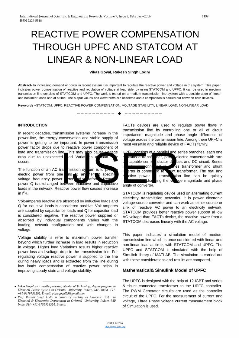
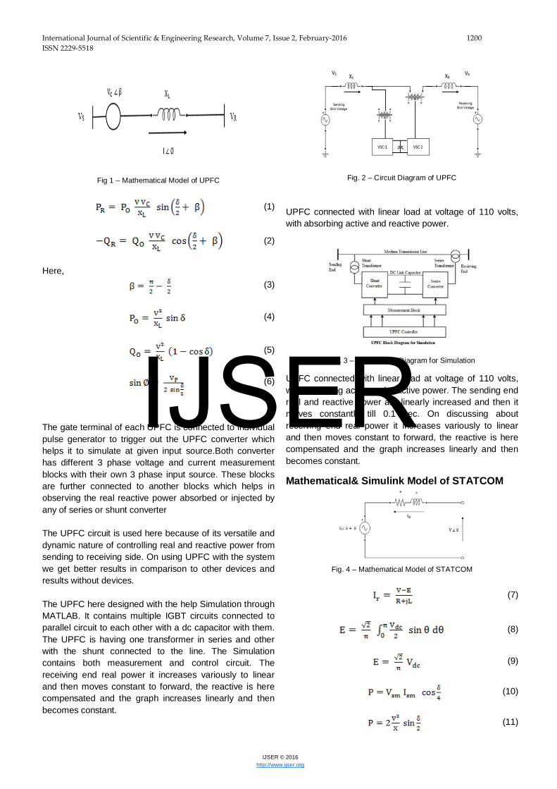
Fig. 2 – Circuit Diagram of UPFC
UPFC connected with linear load at voltage of 110 volts, with absorbing active and reactive power.
Fig. 3 – UPFC Block Diagram for Simulation
UPFC connected with linear load at voltage of 110 volts, with absorbing active and reactive power. The sending end real and reactive power are linearly increased and then it moves constantly till 0.1 sec. On discussing about receiving end real power it increases variously to linear and then moves constant to forward, the reactive is here compensated and the graph increases linearly and then becomes constant.
The STATCOM is here a combination of shunt transformer, lc Filter and an IGBT Converter fed with the pwm generator. The output of STATCOM is calculated at the Pstat port and results is obtained for absorption or injection of reactive power in STATCOM. The results here are obtained with STATCOM is compared with previous block of power system without STATCOM.
The capacitor voltage can be adjusted by controlling the phase angle difference between line voltage and vsc voltage. If the phase angle of line voltage is taken as a reference, the phase angle of vsc voltage is the same as the firing angle of vsc. The dc voltage decreases and reactive power flows into STATCOM, if the firing angles are slightly advanced. Conversely, if the firing angles are slightly delayed, the dc voltage increases and STATCOM supplies reactive power to the bus.
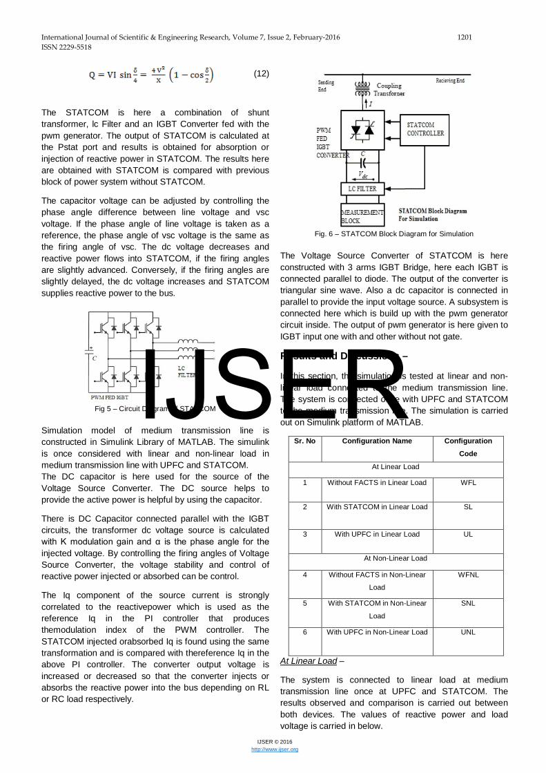
Fig 5 – Circuit Diagram of STATCOM
Simulation model of medium transmission line is constructed in Simulink Library of MATLAB. The simulink is once considered with linear and non-linear load in medium transmission line with UPFC and STATCOM. The DC capacitor is here used for the source of the Voltage Source Converter. The DC source helps to provide the active power is helpful by using the capacitor.
There is DC Capacitor connected parallel with the IGBT circuits, the transformer dc voltage source is calculated with K modulation gain and α is the phase angle for the injected voltage. By controlling the firing angles of Voltage Source Converter, the voltage stability and control of reactive power injected or absorbed can be control.
The Iq component of the source current is strongly correlated to the reactivepower which is used as the reference Iq in the PI controller that produces themodulation index of the PWM controller. The STATCOM injected orabsorbed Iq is found using the same transformation and is compared with thereference Iq in the above PI controller. The converter output voltage is increased or decreased so that the converter injects or absorbs the reactive power into the bus depending on RL or RC load respectively.
Fig. 6 – STATCOM Block Diagram for Simulation
The Voltage Source Converter of STATCOM is here constructed with 3 arms IGBT Bridge, here each IGBT is connected parallel to diode. The output of the converter is triangular sine wave. Also a dc capacitor is connected in parallel to provide the input voltage source. A subsystem is connected here which is build up with the pwm generator circuit inside. The output of pwm generator is here given to IGBT input one with and other without not gate.
Results and Discussions –
In this section, the simulation is tested at linear and non-linear load connected to the medium transmission line. The system is connected once with UPFC and STATCOM to the medium transmission line. The simulation is carried out on Simulink platform of MATLAB.
Sr. No Configuration Name Configuration
Code
At Linear Load
1 Without FACTS in Linear Load WFL
2 With STATCOM in Linear Load SL
3 With UPFC in Linear Load UL
At Non-Linear Load
4 Without FACTS in Non-Linear
Load
WFNL
5 With STATCOM in Non-Linear
Load
SNL
6 With UPFC in Non-Linear Load UNL
At Linear Load –
The system is connected to linear load at medium transmission line once at UPFC and STATCOM. The results observed and comparison is carried out between both devices. The values of reactive power and load voltage is carried in below.
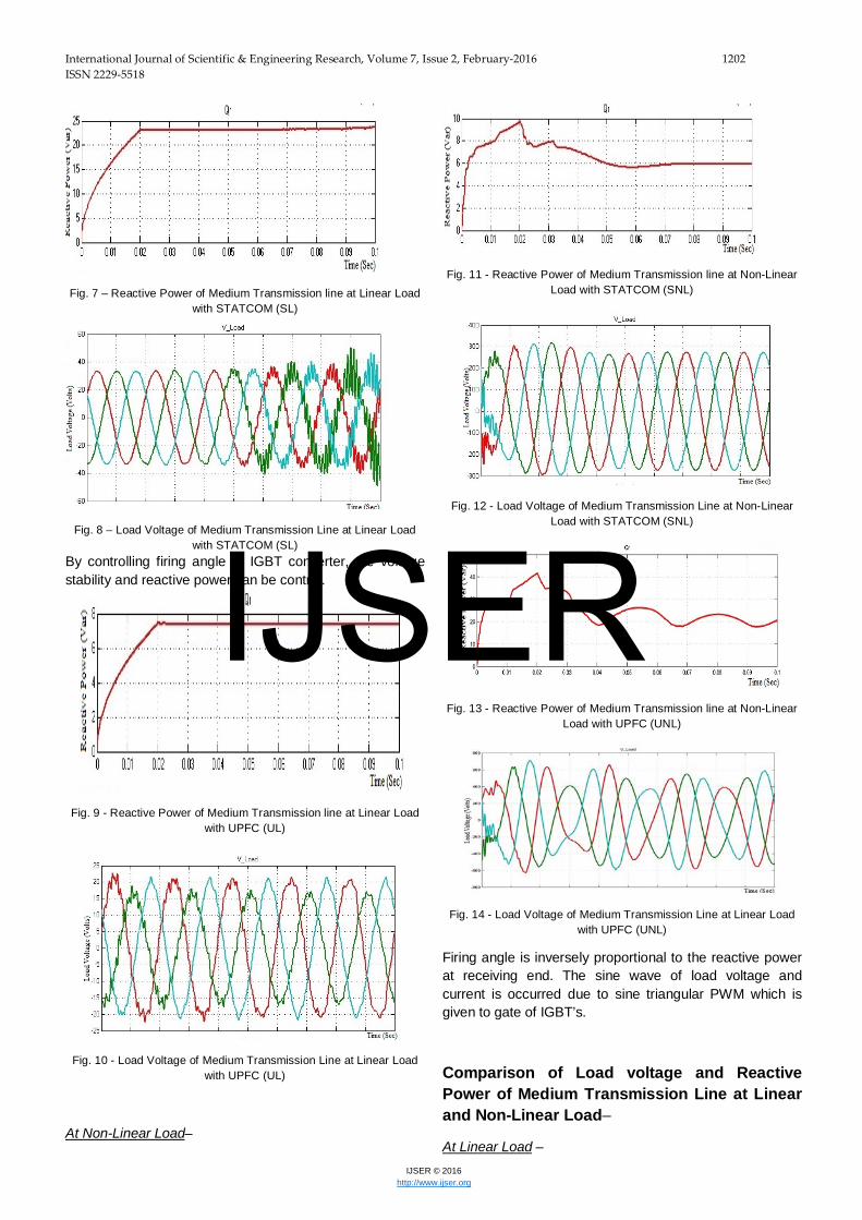
Fig. 7 – Reactive Power of Medium Transmission line at Linear Load with STATCOM (SL)
Fig. 8 – Load Voltage of Medium Transmission Line at Linear Load with STATCOM (SL)
By controlling firing angle of IGBT converter, the voltage stability and reactive power can be control.
Fig. 9 - Reactive Power of Medium Transmission line at Linear Load with UPFC (UL)
Fig. 10 - Load Voltage of Medium Transmission Line at Linear Load with UPFC (UL)
At Non-Linear Load–
Fig. 11 - Reactive Power of Medium Transmission line at Non-Linear Load with STATCOM (SNL)
Fig. 12 - Load Voltage of Medium Transmission Line at Non-Linear Load with STATCOM (SNL)
Fig. 13 - Reactive Power of Medium Transmission line at Non-Linear Load with UPFC (UNL)
Fig. 14 - Load Voltage of Medium Transmission Line at Linear Load with UPFC (UNL)
Firing angle is inversely proportional to the reactive power at receiving end. The sine wave of load voltage and current is occurred due to sine triangular PWM which is given to gate of IGBT’s.
Comparison of Load voltage and Reactive Power of Medium Transmission Line at Linear and Non-Linear Load–
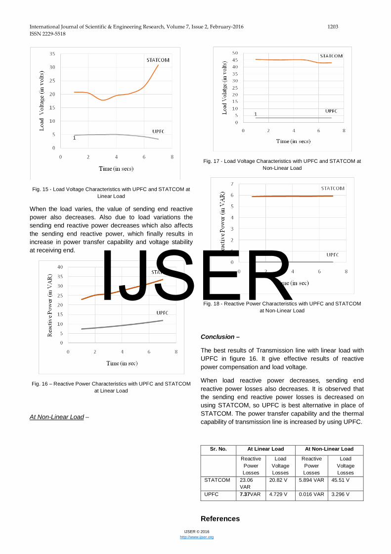
Fig. 15 - Load Voltage Characteristics with UPFC and STATCOM at Linear Load
When the load varies, the value of sending end reactive power also decreases. Also due to load variations the sending end reactive power decreases which also affects the sending end reactive power, which finally results in increase in power transfer capability and voltage stability at receiving end.
Fig. 16 – Reactive Power Characteristics with UPFC and STATCOM at Linear Load
At Non-Linear Load –
Fig. 17 - Load Voltage Characteristics with UPFC and STATCOM at Non-Linear Load
Fig. 18 - Reactive Power Characteristics with UPFC and STATCOM at Non-Linear Load
Conclusion –
The best results of Transmission line with linear load with UPFC in figure 16. It give effective results of reactive power compensation and load voltage.
When load reactive power decreases, sending end reactive power losses also decreases. It is observed that the sending end reactive power losses is decreased on using STATCOM, so UPFC is best alternative in place of STATCOM. The power transfer capability and the thermal capability of transmission line is increased by using UPFC.
[1]. K. R. Padiyar, “FACTs Controllers in Power Transmission
and Distribution”, New Age International (P)
Limited, Publishers. 2007.
[2]. Anulekha Saha, Priyanath Das and AjoykumarChakraborty,”Performance Analysis and Comparison of Various FACTS Devices in Power System”, International Journal of Computer Applications, Volume 46-No.15, May2012.
[3]. Bindeswar singh, et al “Introduction to FACTS Controller: Critical Review”, International Journal of Reviews in Computing, E-ISSN: 2076-3336, Vol.8,31st December 2011, [4]. N. G. Hingorani, “Power Electronics in Electric Utilities: Role of Power Electronics in Future Power Systems”, Proceedings of the IEEE, Vol.76, NO. 4, pp 481-482, April 1988. [5]. L. Gyugyi, “Solid-State Synchronous Voltage Sources for Dynamic Compensation and Real-Time Control of AC Transmission Lines”, Emerging Practices in Technology, IEEE Standards Press, Vol. 9, pp. 904 – 911, April 1993. [6]. Kannan Sreenivasachar, Jayaram, S. and Salama, M.M.A. “Dynamic stability improvement of multi-machine power system with UPFC”, Electric Power Systems Research, Vol. 55, pp. 27-37, 2000. [7]. Toufan, M., Annakkage, U.D. “Simulation of the unified power flow controller performance using PSCAD/EMTDC”, Electric power systems research, Vo. 46, pp. 67-75, 1998. [8]. X. Wang, J.R. McDonald, Modern power system planning, McGraw-Hill, 1994. [9]. Loi Lei Lai, Power system restructuring and deregulation: trading, performance and information technology, Wiley, 2001. [10]. Roger C. Dugan, Electrical power systems quality, 2nd edition, McGraw-Hill, 2003. [11]. Barry W. Kennedy, “Power Quality Primer”, McGraw Hill, 2000. [12]. Roger C. Dugan, Mark F. McGranaghan, H. Wayne Beaty., Electrical power systems quality, McGraw-Hill, 1996 [13]. Gyugyi, L.; “A Unified Power Flow Control Concept for Flexible AC Transmission Systems,” IEE Proceedings on Generation, Transmission and Distribution, vol. 139, no. 4, pp. 323-331, July 1992. [14]. Larsen, E.; Miller, N.; Nilsson, S.; Lindgren, S.; “Benefits of GTO-Based Compensation Systems for Electric Utility Applications,” IEEE Trans. on Power Delivery, vol. 7, no. 4, pp. 2056-2064, Oct. 1992. [15]. Hingorani, N.G.; “Flexible AC Transmission,” IEEE Spectrum, vol. 30, no. 4, pp. 40-45, Apr. 1993. [16]. Noroozian, M.; Anderson G.; “Power Flow Control by use of Controllable Series Components,” IEEE Trans. on Power Delivery, vol. 8, no. 3, pp. 1420-1429, July 1993. [17]. Matakas, L.; Masada, E.; “Multi Converter Implementation by Parallel Associationof Voltage Source Converters-Control Method,” 5th European Conference on Power Electrical and Application, vol. 4, pp. 35-40, 1993. [18]. Gyugyi, L.; Schauder, C.D.; Williams, S.L.; Rietman, T.R.; Torgerson, D.R.; Edris, A.; “The unified power flow controller: a new approach to power transmission control,” IEEE Transactions on Power Delivery, vol.10, no.2, pp.1085-1097, Apr. 1995. [19]. Galiana, F.D.; Almeida, K.; Toussaint, M.; Griffin, J.; Atanackovic, D.; Ooi, B.T.; McGillis, D.T.; “Assessment and control of the impact of FACTS devices on power system performance,” IEEE Transactions on Power Systems, vol.11, no.4, pp.1931-1936, Nov. 1996. [20]. Nabavi Naiki, A.; Iravani, M.R.; “Steady State and Dynamic Models of UPFCfor Power System Studies,” IEEE Trans on Power Systems, vol.11, no.4, pp. 1937-1945, Nov. 1996. [21]. Kannan, S.; Jayaram, S.; Salama, M.M.A.; “Real and reactive power coordination for a unified power flow controller,” IEEE Transactions on Power Systems, vol.19, no.3, pp. 1454- 1461, Aug. 2004.
[22]. Hossam-Eldin, A.A.; Elrefaie, H.; Mohamed, G.K.; “Study and simulation of the unified power flow controller effect on power systems,” Power Systems Conference, (MEPCON). Eleventh International Middle East, vol.2, pp.461-467, Dec. 2006. [23]. Manju, P.; Subbiah, V.; “Intelligent control of Unified Power Flow Controller for stability enhancement of transmission systems,” (ICACC), 2nd International Conference on Advanced Computer Control, vol.3, pp.61-64, Mar. 2010. [24]. Bian, J.; Ramey, D. G.; Nelson, R. J.; Edris, A.; “A Study of Equipment Sizes and Constraints for a Unified Power Flow Controller,” Proceedings IEEE T&D Conference, 1996. [25]. Zhang, Y. and Milanovic, J. V. “Techno-economic improvement of voltage sag performance with facts devices,” Presented at the 9th Int. Conf. Electrical Power Quality and Utilization, Barcelona, Spain, 2006. [26]. Hingorani, N.G. and Gyugyi, L. “Understanding FACTs, Concepts and Technology of Flexible AC Transmission Systems”, IEEE Press, New York. 2000. [27]. SaminaElyas, R.K. Nema and GayatriAgnihotri “Power Flow Control with UPFC in Power Transmission System” World Academy of science, Engineering and Technology, Vol. 47, pp. 338- 342, 2008. [28]. Abdul Haleem, RavireddyMalgireddy, “Power Flow Control with Static Synchronous Series Compensator (SSSC)”, International Conference on Science and Engineering (ICSE), ISBN: 978-981-08-7931-0, 2011. [29]. S. Tara Kalyani, G. Tulasiram Das, “Simulation of Real and Reactive Power Flow Control with UPFC connected to a Transmission Line”, Journal of Theoretical and Applied Information Technology, 2008. [30]. Dawn, S, “Maximization of social welfare by optimal
allocation of UPFC with wind power generator in deregulated
electricity market”, International Conference on Advanced
Communication Control and Computing Technologies (ICACCCT),
1. Vikas Goyal: The first author belongs to City Ratlam, in Madhya Pradesh State in India. He is pursuing M.Tech in electrical power system his PG in Electrical Power System, He is currently working on the topics Reactive Power Compensation, UPFC Modification Model, FACTS Devices with linear and Non-Linear Load.
2. Rakesh Singh Lodhi is Associate Professor, Department of Electrical & Electronics Engineering, Oriental University, Indore (MP). He is a BE (Electrical & Electronics Engineering) from RGPV University and a postgraduate in Power Electronics from Shri Govindram Seksaria Institute of Technology and Science, Indore (MP). He is in academics and research since


![Reactive Power Compensation[1]](https://static.documents.pub/doc/80x56/577ccf3f1a28ab9e788f40c0/reactive-power-compensation1.jpg)


