35
Reactive Power Requirements and Financial Compensation Issue Paper May 22, 2015
Reactive Power Requirements and Financial Compensation
Issue Paper
May 22, 2015
California ISO Issue Paper
CAISO/M&IP/C.Bentley/MQ&RI/C.Loutan 2 May 22, 2015
Table of Contents 1. Document change tracking ............................................................................................ 3
2. Executive summary ....................................................................................................... 3
3. Plan for stakeholder engagement .................................................................................. 4
4. Purpose ........................................................................................................................ 5
5. Current reactive power capability and provision ............................................................ 6
5.1. Generation Interconnection Process ................................................................................ 7
5.2. Transmission Planning Process .....................................................................................10
5.3. Annual Local Capacity Technical Study ..........................................................................11
6. Issues with Generation Interconnection Process ..........................................................11
6.1. Case studies: San Diego/Imperial Valley .......................................................................13
6.2. Over-generation conditions.............................................................................................14
7. Uniform requirement for asynchronous resources ........................................................15
7.1. Uniform requirements adopted in other jurisdictions .......................................................16
8. Uniform requirement ISO regulation background .........................................................17
9. Proposed asynchronous resource requirements ..........................................................19
9.1. Proposed requirements for Asynchronous Generating Facilities .....................................20
9.2. Operational requirements for Asynchronous Generating Facilities ..................................21
10. Uniform requirement technical issues...........................................................................24
10.1. Hunting ...........................................................................................................................24
10.2. Collective generation projects .........................................................................................24
10.3. Metering and telemetry ...................................................................................................25
10.4. Inverter size ....................................................................................................................25
10.5. Inverter cost ...................................................................................................................26
11. Financial compensation ...............................................................................................27
11.1. Purpose ..........................................................................................................................27
11.2. Regulatory Review .........................................................................................................27
11.3. Compensation options ....................................................................................................27
11.4. Compliance and testing ..................................................................................................30
11.5. Cost allocation ................................................................................................................30
11.6. Other compensation issues ............................................................................................31
12. Next Steps ...................................................................................................................31
13. Appendix A: Summary of ISO/RTO reactive power financial compensation .................32
California ISO Issue Paper
CAISO/M&IP/C.Bentley/MQ&RI/C.Loutan 3 May 22, 2015
1. Document change tracking This initiative is a continuation of the Reactive Power Requirements for Asynchronous Resources initiative. Based on stakeholder feedback and a review of other ISO/RTO reactive power financial compensation policies, the ISO has added financial compensation for reactive power for all resources into the scope of this initiative. Given the large change in scope, the ISO is beginning with an issue paper that includes issues related to reactive power financial compensation. It also includes sections on synchronous resource requirements and additional technical issues related to asynchronous resources raised by stakeholders in comments and at the technical working group meeting on April 22, 2015.
2. Executive summary
The ISO is launching this initiative to propose a uniform requirement for asynchronous1 resources to provide reactive power capability and voltage regulation. This proposed new approach will replace the current system impact study approach to assess whether asynchronous resources must provide reactive capability. Additionally, the ISO is considering a mechanism to compensate units for reactive power capability and provision. Both synchronous and asynchronous resources would be eligible for compensation under any proposed financial compensation mechanism.
Since 2010, when the ISO previously proposed a requirement for asynchronous resources, the rapid expansion of asynchronous renewable resources has resulted in high ratios of asynchronous to synchronous generation during a portion of the operating day. Renewables are rapidly displacing the conventional generating facilities that have historically provided reactive power support to maintain voltage levels required for the efficient delivery of real power to serve electric load.
As the supply of synchronous generation declines, ISO interconnection system impact studies more frequently require asynchronous resources to provide reactive power capability as a condition of interconnecting. Given the changes to the resource fleet that the ISO is experiencing, the current approach has the risk that once an asynchronous project interconnects and is in operation, the actual system conditions could be far different than the conditions the ISO studied during the interconnection process. Thus the grid is increasingly likely to have a reactive power deficiency. Modifications to the current interconnection study approach to mitigate its shortcomings would require an increase in the overall process timeline and an increase in the cost of interconnection studies.
Instead, the ISO is proposing to adopt, on a going forward basis, a uniform requirement for all resources, including asynchronous resources, to provide reactive power capability and automatic voltage control. Requiring asynchronous resources to have the capability to provide
1 Asynchronous resource is a generator that does not use mechanical rotors that synchronize with system frequency.
California ISO Issue Paper
CAISO/M&IP/C.Bentley/MQ&RI/C.Loutan 4 May 22, 2015
reactive support and automatically control voltage schedules at the point of interconnection is a more reliable, efficient, and equitable approach than examining this issue through a system impact study. The ISO is informed that manufacturers routinely include this capability in standard inverters used by asynchronous resources and therefore this approach creates virtually no incremental capital costs for interconnection customers. This proposed approach will also follow approaches adopted by other jurisdictions.
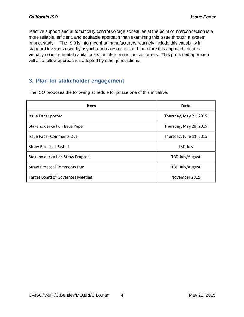
3. Plan for stakeholder engagement
The ISO proposes the following schedule for phase one of this initiative.
Item Date
Issue Paper posted Thursday, May 21, 2015
Stakeholder call on Issue Paper Thursday, May 28, 2015
Issue Paper Comments Due Thursday, June 11, 2015
Straw Proposal Posted TBD July
Stakeholder call on Straw Proposal TBD July/August
Straw Proposal Comments Due TBD July/August
Target Board of Governors Meeting November 2015
California ISO Issue Paper
CAISO/M&IP/C.Bentley/MQ&RI/C.Loutan 5 May 22, 2015
4. Purpose
Electric power that flows on transmission and distribution lines is composed of two components: real power and reactive power. Real power is measured in watts (W) and reactive power is measured in volt amps reactive (VAR). Real power serves electric loads and is optimized through the ISO energy markets. Reactive power maintains voltage levels, enables real power to serve electric load efficiently and is dispatched to maintain a voltage schedule. Real power and reactive power function in an integrated, interdependent, and inseparable manner in a modern, widespread alternating current (AC) electric grid.
Because of this interdependency, an AC electric system must have the right amount of reactive power to support the delivery of real power. Conventional synchronous generation resources are the primary source of reactive power on the transmission system. Insufficient reactive power on the interconnected grid will cause unstable conditions that jeopardize delivery of power to end-use customers. A mismatch in the amount of reactive power needed will degrade the ability for any generation resource, including renewable resources, to operate. Adequate reactive power is therefore fundamental to the operation of generation resources. Without adequate supplies of reactive power, the electric grid may malfunction or even catastrophically fail due to voltage collapse. Likewise, without the capability to absorb reactive power, voltage levels can exceed acceptable operating limits causing equipment to trip off line.
Virtually any properly equipped generating facility can supply reactive power to the system, as supplemented by transmission equipment. All synchronous generators - resources with a mechanical motor that rotates synchronized with the system frequency - in the ISO produce and absorb reactive power and maintain a voltage schedule set by the Participating Transmission Owner (PTO) or ISO. Examples of synchronous generators include nuclear power plants, hydro plants and natural-gas fired generators such as peaking units and combined cycle units.
The shift to sustainable and renewable energy sources such as solar, wind, and energy storage is increasing the proportion of generators on the system that do not use mechanical rotors rotating synchronized with the system. These are asynchronous resources and do not inherently have reactive power capability unless this capability is included as an integrated feature through adding inverters, capacitors, or other means. When asynchronous resources go through the ISO interconnection study process, they may be required to provide reactive power based on a study of the expected system.
Because generation resources are the primary source of reactive power on the transmission system, the proliferation of asynchronous resources in conjunction with the retirement of large synchronous generators closer to the load centers is significantly changing the landscape of the interconnected power grid. As the need for and location of reactive power resources changes because of future additions of asynchronous resources and previously unplanned requirements, it will become necessary for reliability for all interconnected resources to provide reactive power.
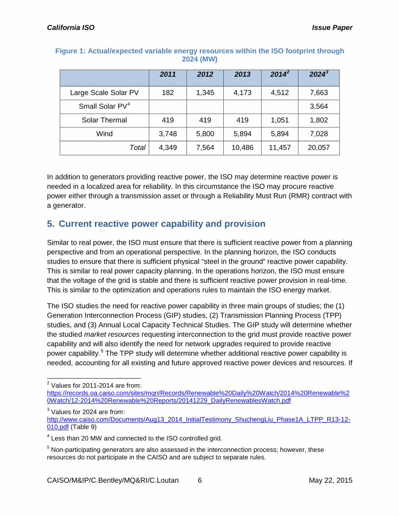
Table 1 below shows the actual/expected increase in variable energy resources (VERs) through 2024.
California ISO Issue Paper
CAISO/M&IP/C.Bentley/MQ&RI/C.Loutan 6 May 22, 2015
Figure 1: Actual/expected variable energy resources within the ISO footprint through 2024 (MW)
2011 2012 2013 20142 20243
Large Scale Solar PV 182 1,345 4,173 4,512 7,663
Small Solar PV4 3,564
Solar Thermal 419 419 419 1,051 1,802
Wind 3,748 5,800 5,894 5,894 7,028
Total 4,349 7,564 10,486 11,457 20,057
In addition to generators providing reactive power, the ISO may determine reactive power is needed in a localized area for reliability. In this circumstance the ISO may procure reactive power either through a transmission asset or through a Reliability Must Run (RMR) contract with a generator.
5. Current reactive power capability and provision
Similar to real power, the ISO must ensure that there is sufficient reactive power from a planning perspective and from an operational perspective. In the planning horizon, the ISO conducts studies to ensure that there is sufficient physical “steel in the ground” reactive power capability. This is similar to real power capacity planning. In the operations horizon, the ISO must ensure that the voltage of the grid is stable and there is sufficient reactive power provision in real-time. This is similar to the optimization and operations rules to maintain the ISO energy market.
The ISO studies the need for reactive power capability in three main groups of studies; the (1) Generation Interconnection Process (GIP) studies, (2) Transmission Planning Process (TPP) studies, and (3) Annual Local Capacity Technical Studies. The GIP study will determine whether the studied market resources requesting interconnection to the grid must provide reactive power capability and will also identify the need for network upgrades required to provide reactive power capability.5 The TPP study will determine whether additional reactive power capability is needed, accounting for all existing and future approved reactive power devices and resources. If
2 Values for 2011-2014 are from: https://records.oa.caiso.com/sites/mqri/Records/Renewable%20Daily%20Watch/2014%20Renewable%20Watch/12-2014%20Renewable%20Reports/20141229_DailyRenewablesWatch.pdf 3 Values for 2024 are from: http://www.caiso.com/Documents/Aug13_2014_InitialTestimony_ShuchengLiu_Phase1A_LTPP_R13-12-010.pdf (Table 9) 4 Less than 20 MW and connected to the ISO controlled grid. 5 Non-participating generators are also assessed in the interconnection process; however, these resources do not participate in the CAISO and are subject to separate rules.
California ISO Issue Paper
CAISO/M&IP/C.Bentley/MQ&RI/C.Loutan 7 May 22, 2015
additional reactive power capability is required according to the TPP study, the ISO will identify the most effective and efficient transmission asset to provide reactive power. The Annual Local Capacity Study finds the minimum resource adequacy capacity needed to meet the Local Capacity Requirements criteria including reactive power needs. In very rare circumstances there may be no capacity available in the local area to meet the requirement and the ISO may procure resources under a Reliability Must Run (RMR) contract. The ISO may also perform ad hoc operational reactive power capability studies that result in an RMR contract; however, these studies are done infrequently and find the need for additional reactive power capability only in highly unusual situations.
Market resources, transmission assets, and resources under RMR contracts all provide reactive power capability to the grid, but each type has unique participation and reactive power provision rules. Market resources must provide reactive power within a standard range that is defined in the tariff ancillary services rules. Transmission assets and RMR resources must provide reactive power according to a resource-specific contract. The following paragraphs describe each study, resource type, and participation and provision rules in more detail.
5.1. Generation Interconnection Process In the generation interconnection process, all synchronous resources must provide their reactive power output information.6 For asynchronous resources, the ISO uses a case-by-case, system impact study approach to assess whether these resources must provide reactive power supply/absorption capability. The process is further described below. Both synchronous and asynchronous resources that go through the interconnection process may participate in the ISO as market resources and must meet the provision standards in the tariff and the generator-specific interconnection agreement.
Assessment of asynchronous resources 5.1.1.The ISO uses a case-by-case, system impact study approach to assess whether asynchronous resources must provide reactive power supply/absorption capability. The ISO conducts this as part of the interconnection process, and it requires an assessment of asynchronous resources within a cluster to determine whether a resource must provide reactive power capability to interconnect to the system based on a range of operating conditions. For asynchronous resources within the cluster study process, the ISO must identify if a resource must provide reactive power capability in order to safely and reliably interconnect the resource.7 If the ISO identifies such a need, then the resource must have at least a +/- 0.95 power factor range at its Point of Interconnection. If the study results do not demonstrate this need, the ISO does not
6 i.e. provide information on the maximum and minimum VAR capabilities 7 Asynchronous resources using the ISO’s independent study process must provide reactive power capability without the need for the ISO to determine the need for that capability though an interconnection system impact study. Cal. Indep. Sys. Operator Corp.149 FERC ¶ 61,100 (2014). http://elibrary.ferc.gov/idmws/common/opennat.asp?fileID=13674514
California ISO Issue Paper
CAISO/M&IP/C.Bentley/MQ&RI/C.Loutan 8 May 22, 2015
currently require the resource to provide reactive power capability or impose a requirement to control voltage.
The current study methodology in the ISO generation cluster study was reviewed by stakeholders and subsequently adopted in 2011. A reactive power capability deficiency analysis is performed in each cluster Phase II interconnection study to determine:
• Whether the asynchronous facilities proposed by the interconnection projects in the current cluster must provide 0.95 leading/lagging power factor at the Point of Interconnection (POI).
• Whether network upgrades, including system resources that provide reactive power, are needed to mitigate reactive power deficiency.
First, the ISO conducts the study assuming unity power factor8 for the asynchronous facilities of the new interconnection projects in the current cluster. Based on two scenarios, a peak and an off-peak, with and without current cluster projects, the ISO develops four base cases for each study group:
• Case 1: Peak pre-cluster base case without the current cluster projects.
• Case 2: Peak post-cluster base case with the current cluster projects modeled at unity power factor.
• Case 3: Off-peak pre-cluster base case without the current cluster projects.
• Case 4: Off-peak post-cluster base case with the current cluster projects modeled at unity power factor.
Second, The ISO performs contingency analysis on all four base cases. The study results determine:
• Whether adding current cluster projects causes normal voltages out of the allowable normal min/max range.
• Whether adding current cluster projects causes post-contingency voltages out of the allowable post-transient min/max range.
• Whether adding current cluster projects causes excessive voltage deviation from the pre-contingency level.
• Third, the ISO further analyzes critical contingencies that result in excessive voltage deviation using the post-transient power flow. In particular, the ISO might perform an additional analysis to determine the post-transient voltage stability. If significant power transfer occurs, the pre-contingency power transfer can be increased
8 Power factor is the ratio between a generator’s real power (MW) and apparent power (MVA), where apparent power is the vector sum of the real and reactive power. The power factor range can be leading or lagging. Unity power factor is where the current and voltage are in synch and no reactive power is produced.
California ISO Issue Paper
CAISO/M&IP/C.Bentley/MQ&RI/C.Loutan 9 May 22, 2015
according to applicable voltage performance criteria of the Western Electricity Coordinating Council. The post transient voltage stability analysis will determine:
• Whether the system has sufficient reactive margin according to the planning standards.
If the results indicate reactive power deficiencies, the ISO requires the asynchronous generators in the cluster study group to provide 0.95 leading/lagging power factors at the Point of Interconnection.
Next, the ISO modifies the four base cases above to model the required reactive power capability and conducts the same contingency analysis and post-transient voltage stability analysis again. If the new study results still indicate reactive power deficiencies, the ISO will require transmission system upgrades to mitigate the problem.
Using this approach, the ISO has assessed 187 asynchronous projects (approximately 17,000 MW) through mid-2014 requesting interconnection to the ISO controlled grid and required almost three-fourths of these projects (approximately 12,000 MW) to provide reactive power capability. This means that slightly more than one-fourth of these projects were not required to provide reactive power capability.
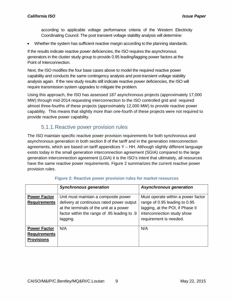
Reactive power provision rules 5.1.1.The ISO maintain specific reactive power provision requirements for both synchronous and asynchronous generation in both section 8 of the tariff and in the generation interconnection agreements, which are based on tariff appendices Y – HH. Although slightly different language exists today in the small generation interconnection agreement (SGIA) compared to the large generation interconnection agreement (LGIA) it is the ISO’s intent that ultimately, all resources have the same reactive power requirements. Figure 2 summarizes the current reactive power provision rules.
Figure 2: Reactive power provision rules for market resources
Synchronous generation Asynchronous generation
Power Factor Requirements
Unit must maintain a composite power delivery at continuous rated power output at the terminals of the unit at a power factor within the range of .95 leading to .9 lagging.
Must operate within a power factor range of 0.95 leading to 0.95 lagging, at the POI, if Phase II interconnection study show requirement is needed.
Power Factor Requirements Provisions
N/A N/A
California ISO Issue Paper
CAISO/M&IP/C.Bentley/MQ&RI/C.Loutan 10 May 22, 2015
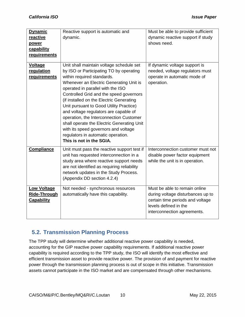
Dynamic reactive power capability requirements
Reactive support is automatic and dynamic.
Must be able to provide sufficient dynamic reactive support if study shows need.
Voltage regulation requirements
Unit shall maintain voltage schedule set by ISO or Participating TO by operating within required standards. Whenever an Electric Generating Unit is operated in parallel with the ISO Controlled Grid and the speed governors (if installed on the Electric Generating Unit pursuant to Good Utility Practice) and voltage regulators are capable of operation, the Interconnection Customer shall operate the Electric Generating Unit with its speed governors and voltage regulators in automatic operation. This is not in the SGIA.
If dynamic voltage support is needed, voltage regulators must operate in automatic mode of operation.
Compliance Unit must pass the reactive support test if unit has requested interconnection in a study area where reactive support needs are not identified as requiring reliability network updates in the Study Process. (Appendix DD section 4.2.4)
Interconnection customer must not disable power factor equipment while the unit is in operation.
Low Voltage Ride-Through Capability
Not needed - synchronous resources automatically have this capability.
Must be able to remain online during voltage disturbances up to certain time periods and voltage levels defined in the interconnection agreements.
5.2. Transmission Planning Process The TPP study will determine whether additional reactive power capability is needed, accounting for the GIP reactive power capability requirements. If additional reactive power capability is required according to the TPP study, the ISO will identify the most effective and efficient transmission asset to provide reactive power. The provision of and payment for reactive power through the transmission planning process is out of scope in this initiative. Transmission assets cannot participate in the ISO market and are compensated through other mechanisms.
California ISO Issue Paper
CAISO/M&IP/C.Bentley/MQ&RI/C.Loutan 11 May 22, 2015
5.3. Annual Local Capacity Technical Study The Annual Local Capacity Study finds the minimum capacity needed to meet the Local Capacity Requirement criteria including reactive power needs. If this study identifies a reactive power need, the load serving entities in the local area are informed and allowed to make an informed procurement decision that could mitigate the need. If the LSEs do not procure enough resource adequacy capacity to meet this need, ISO may procure additional resources to meet the need through its back stop authority role. This could be done either through the Capacity Procurement Mechanism (CPM) if both reactive and real power is needed or through a Reliability Must Run (RMR) contract if ultimately only reactive power is needed.
Resources procured through the CPM are market resources and have the same participation and provision standards as resources that are required to provide reactive power through the Generation Interconnection Process. These resources get an additional capacity payment for their real power capability and must comply with the resource adequacy rules. They are also compensated through the CPM payment for providing reactive power as well as additional market revenues for providing real power.
Resources procured through RMR contracts must maintain a voltage schedule in a local area and do not participate in the ISO energy market for real power. Currently the ISO has two synchronous condensers under RMR contracts to maintain grid reliability. All fixed and variable costs, including the energy and O&M costs to provide reactive power are recovered through the RMR contract and not through the market or resource adequacy contract.
6. Issues with Generation Interconnection Process The case-by-case, system impact study approach to assess whether asynchronous resources must provide reactive capability has several shortcomings.
First, system impact study may not require that every project provide reactive power capability because it may conclude there will be sufficient reactive power on the transmission system due to the capabilities of existing generators with reactive power capability and other reactive power devices on the transmission system. However, a glaring weakness with this approach is that such a study cannot reasonably anticipate all operating conditions in which resources with reactive power capability or reactive power devices on the transmission grid will be out of service – either due to retirement, or forced or planned outage –when reactive power needs arise. The case-by-case approach relies heavily on the assumptions of future conditions, which may not prove true and does not plan for unpredicted events. Once an asynchronous project is interconnected and is commercially operable, actual system conditions could be far different from the conditions studied.
System impact studies do not – and cannot within current process timelines – cover all operational scenarios or future conditions that may require a resource to provide reactive power
California ISO Issue Paper
CAISO/M&IP/C.Bentley/MQ&RI/C.Loutan 12 May 22, 2015
capability.9 Interconnection studies are time consuming and iterative in nature.10 If the ISO studied all possible operating conditions, potential outage schedules, and potential retirements for existing resources to more comprehensively assess the need for an asynchronous resource to provide reactive power support and absorption capability, the cost and time required for the system impact study process would increase. The ISO estimates that to enhance its system impact study efforts to account for a more robust set of operating conditions would take at least another four months of study for each interconnection cluster at an additional cost of approximately $2 million for each interconnection cluster. Currently, the ISO must complete the interconnection study processes within 205 days. To study a more robust set of operating conditions the ISO must undertake roughly ten times more study work to make the interconnection system impact study comparable to the transmission planning process.
Even if the ISO completes these system impact studies in a timely and cost–effective manner, it is impractical to identify and examine all possible operation conditions. Deficiencies in reactive power support and absorption may not always occur during system peak and often can occur on days with high levels of variable energy resources and low demand periods or during periods when transmission infrastructure is out of service. In addition, a significant portion of the generating fleet is out on maintenance during the non-summer months, which places a level of subjectivity in studying off-peak operating scenarios because of the combinations of resources out on maintenance, load levels and asynchronous production levels.
If an unstudied operating condition occurs that results in unanticipated reactive power needs, then asynchronous resources unable to provide reactive power may adversely affect the voltage stability of the system. Absent sufficient voltage, asynchronous resources may face operational issues (e.g. wind facilities may have to operate at lower than optimal levels until they could provide voltage control even though interconnection studies did not detect voltage issues).11 By interconnecting to the transmission system without a sufficient reactive margin at its POI, an asynchronous resource may degrade both the system and its own operations.12
Second, if a system impact study identifies a need for reactive power support in a queue cluster and requires asynchronous resources within that cluster to provide reactive power, these resources compensate for all earlier queued resources for which the transmission provider identified no reactive power need. This “leaning” of asynchronous resources without reactive power capability on the reactive power support of other resources and reactive power devices unfairly distributes the costs of providing reactive power. It also raises questions regarding the inequities between resources that have incurred costs to provide reactive support to the
9 April 17, 2012 FERC Technical Conference on Reactive Power Resources (AD12-10-000), Transcript at 20:23-21:15. http://www.ferc.gov/CalendarFiles/20120426074709-AD12-10-04-17-12.pdf
10 Id. at 17:8-16. 11 Id. 150:24-152:16. 12 Id. 43:4-18.
California ISO Issue Paper
CAISO/M&IP/C.Bentley/MQ&RI/C.Loutan 13 May 22, 2015
transmission system and those resources that have not, based on the mere happenstance of when they were studied.
Last, the system impact study approach potentially introduces unknown investment risks because customers with asynchronous generating projects in the ISO’s queue only learn of the need to provide reactive power during the second phase of the ISO’s interconnection studies. Applying uniform reactive power and voltage control requirements for asynchronous generating facilities provides up-front cost certainty for investors and developers.
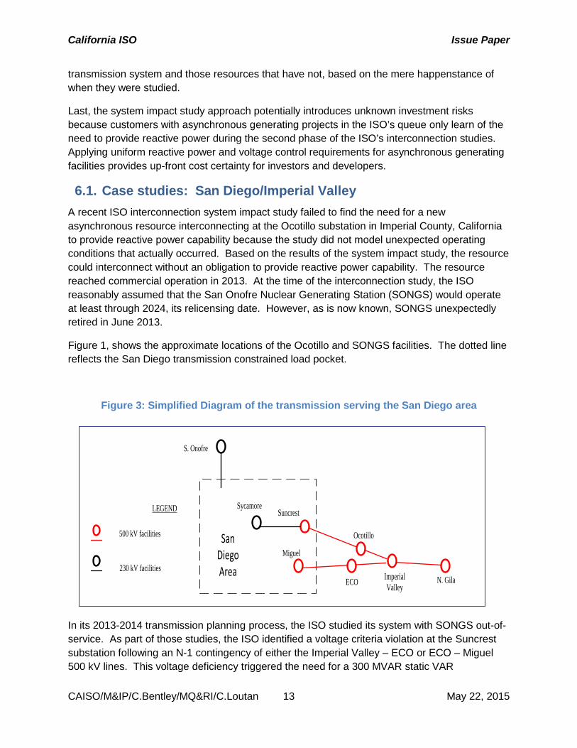
6.1. Case studies: San Diego/Imperial Valley A recent ISO interconnection system impact study failed to find the need for a new asynchronous resource interconnecting at the Ocotillo substation in Imperial County, California to provide reactive power capability because the study did not model unexpected operating conditions that actually occurred. Based on the results of the system impact study, the resource could interconnect without an obligation to provide reactive power capability. The resource reached commercial operation in 2013. At the time of the interconnection study, the ISO reasonably assumed that the San Onofre Nuclear Generating Station (SONGS) would operate at least through 2024, its relicensing date. However, as is now known, SONGS unexpectedly retired in June 2013.
Figure 1, shows the approximate locations of the Ocotillo and SONGS facilities. The dotted line reflects the San Diego transmission constrained load pocket.
Figure 3: Simplified Diagram of the transmission serving the San Diego area
LEGEND
500 kV facilities
230 kV facilities Imperial Valley
N. Gila
Miguel
Suncrest
Ocotillo
ECO
Sycamore
S. Onofre
San Diego Area
In its 2013-2014 transmission planning process, the ISO studied its system with SONGS out-of-service. As part of those studies, the ISO identified a voltage criteria violation at the Suncrest substation following an N-1 contingency of either the Imperial Valley – ECO or ECO – Miguel 500 kV lines. This voltage deficiency triggered the need for a 300 MVAR static VAR
California ISO Issue Paper
CAISO/M&IP/C.Bentley/MQ&RI/C.Loutan 14 May 22, 2015
compensator at the Suncrest substation. An additional assessment showed that if the asynchronous resource at Ocotillo were providing reactive power through its inverters, the reactive power need at Suncrest would have been reduced by 50 MVAR.
Although the ISO would still have identified a reactive power need in its transmission plan based on the closure of SONGs, that need would have been reduced had the ISO determined that resources at the Ocotillo substation needed to have reactive power capability. While SONGS reflects an extraordinary closure, the fundamental point is that transmission providers cannot foresee each and every retirement or operating scenario on its system. A smaller resource that retires may also create an unexpected reactive power deficiency. For example, a two month outage of a combined cycle plant or the loss of a transmission element may easily create unforeseen voltage issues that require the capability to supply or absorb reactive support.
Another ISO interconnection system impact study failed to find the need for a new asynchronous resource interconnecting at the Imperial Valley substation in Imperial County, California to provide reactive power capability because the study did not model unexpected operating conditions that actually occurred. Imperial Valley substation has both synchronous and asynchronous generation connected to it. The asynchronous generation was not required to provide reactive power. In order to reduce flow on heavily loaded transmission lines the ISO identified the need to bypass series capacitors on two nearby 500 kV lines. The loss of one of these 500 kV lines requires the tripping of generation at Imperial Valley substation. However, it was found that tripping the synchronous generation instead of the asynchronous generation resulted in voltage problems. Therefore, the ISO had to design a generation tripping scheme to only trip the asynchronous generation.
While transmission providers can mitigate this deficiency by authorizing new transmission elements, this process involves an unavoidable time lag and results in the costs applied to all transmission ratepayers rather than generating resources. This may also create inequities between conventional resources and resources that have no reactive power requirement. Adoption of uniform requirements for reactive power capability and voltage control at the time of interconnection helps mitigate potential reactive power deficiencies that may affect the ability of resources to deliver real power.
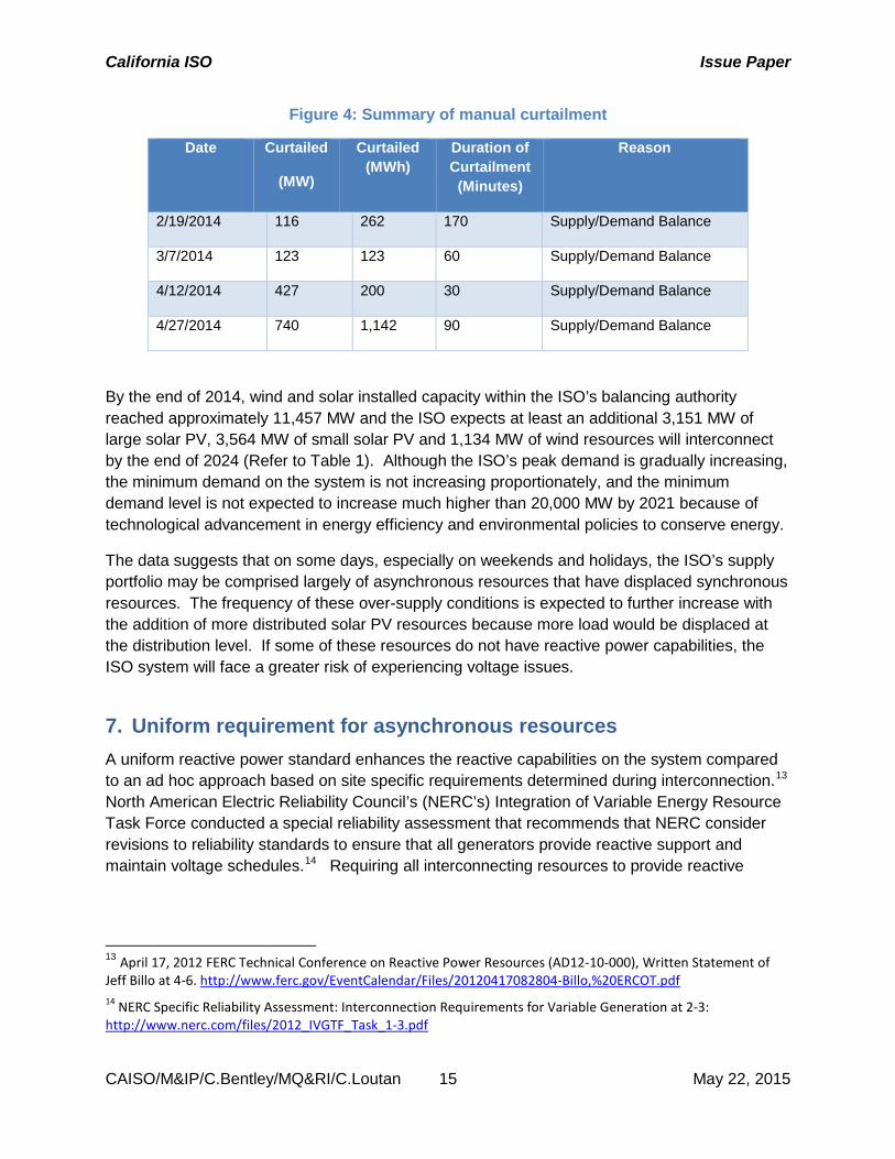
6.2. Over-generation conditions Failure of asynchronous generators to provide reactive power capability can also have implications during over-generation conditions. Based on an analysis of data for 2014 (see Table 3 below), the ISO had to curtail between 116 MW and 740 MW of resources on certain days due to over-supply. During over-supply conditions, the ISO will solicit scheduling coordinators to submit decremental bids as mitigating measures, dispatch down flexible resources based on their decremental bids, and utilize exceptional dispatch to reduce production as needed. If remaining asynchronous resources in operation do not have reactive power capability, the ISO system will face a greater risk of voltage issues.
California ISO Issue Paper
CAISO/M&IP/C.Bentley/MQ&RI/C.Loutan 15 May 22, 2015
Figure 4: Summary of manual curtailment
Date Curtailed
(MW)
Curtailed (MWh)
Duration of Curtailment (Minutes)
Reason
2/19/2014 116 262 170 Supply/Demand Balance
3/7/2014 123 123 60 Supply/Demand Balance
4/12/2014 427 200 30 Supply/Demand Balance
4/27/2014 740 1,142 90 Supply/Demand Balance
By the end of 2014, wind and solar installed capacity within the ISO’s balancing authority reached approximately 11,457 MW and the ISO expects at least an additional 3,151 MW of large solar PV, 3,564 MW of small solar PV and 1,134 MW of wind resources will interconnect by the end of 2024 (Refer to Table 1). Although the ISO’s peak demand is gradually increasing, the minimum demand on the system is not increasing proportionately, and the minimum demand level is not expected to increase much higher than 20,000 MW by 2021 because of technological advancement in energy efficiency and environmental policies to conserve energy.
The data suggests that on some days, especially on weekends and holidays, the ISO’s supply portfolio may be comprised largely of asynchronous resources that have displaced synchronous resources. The frequency of these over-supply conditions is expected to further increase with the addition of more distributed solar PV resources because more load would be displaced at the distribution level. If some of these resources do not have reactive power capabilities, the ISO system will face a greater risk of experiencing voltage issues.
7. Uniform requirement for asynchronous resources A uniform reactive power standard enhances the reactive capabilities on the system compared to an ad hoc approach based on site specific requirements determined during interconnection.13 North American Electric Reliability Council’s (NERC’s) Integration of Variable Energy Resource Task Force conducted a special reliability assessment that recommends that NERC consider revisions to reliability standards to ensure that all generators provide reactive support and maintain voltage schedules.14 Requiring all interconnecting resources to provide reactive
13 April 17, 2012 FERC Technical Conference on Reactive Power Resources (AD12-10-000), Written Statement of Jeff Billo at 4-6. http://www.ferc.gov/EventCalendar/Files/20120417082804-Billo,%20ERCOT.pdf 14 NERC Specific Reliability Assessment: Interconnection Requirements for Variable Generation at 2-3: http://www.nerc.com/files/2012_IVGTF_Task_1-3.pdf
California ISO Issue Paper
CAISO/M&IP/C.Bentley/MQ&RI/C.Loutan 16 May 22, 2015
capability will remedy the shortcomings of the current approach and ensure distribution of the reactive power control throughout the system.15
7.1. Uniform requirements adopted in other jurisdictions To ensure adequate voltage on their transmission systems, other jurisdictions have adopted a uniform reactive power requirement for asynchronous resources. For example, the Electric Reliability Council of Texas, Inc. (ERCOT) adopted a reactive power standard to integrate the build out of competitive renewable energy zones and support the transfer of that supply within the ERCOT region.16 Specifically, ERCOT determined that imposing uniform reactive power obligations across all generation types was necessary because of challenges presented by integrating significant amounts of renewable generation in locations distant from load centers. The ISO faces similar circumstances because it is also integrating significant amounts of asynchronous resources. With ERCOT, applying a uniform reactive power standard to asynchronous resources avoided a situation in which projects interconnecting needed to wait for additional reactive power resources to compensate for unstable voltage conditions on the grid.
Other jurisdictions in North America have also adopted uniform reactive power requirements.17 The Independent Energy System Operator (IESO) in Ontario, Canada requires renewable generators to provide reactive power continuously in the range of 0.95 lagging to 0.95 leading at the POI based on rated active power output, with no determination in system impact study. This is required for safety and/or reliability. The IESO also has voltage control requirements that apply to renewable resources.
The California Public Utilities Commission (CPUC) recently issued a decision adopting modifications to Electric Tariff Rule 21 to capture the technological advances offered by today’s inverters. In Decision 14-12-035,18 the CPUC noted that as greater numbers of renewable generating resources interconnect with the grid, the influence of inverters will grow. The CPUC further noted that today’s inverters have many capabilities including:
• The generation or absorption of reactive power to raise or lower the voltage at its terminals.
• Delivery of power in four quadrants, positive real power and positive reactive power; positive real power and negative reactive power; negative real power and negative reactive power; and negative real power and positive reactive power.
15 April 17, 2012 FERC Technical Conference on Reactive Power Resources (AD12-10-000), Transcript at 20 at 17:7-22. 16 April 17, 2012 FERC Technical Conference on Reactive Power Resources (AD12-10-000), Written Statement of Jeff Billo http://www.ferc.gov/EventCalendar/Files/20120417082804-Billo,%20ERCOT.pdf 17 April 17, 2012 FERC Technical Conference on Reactive Power Resources (AD12-10-000), Transcript at 120:18-121:13. 18 Issued December 18, 2014, in CPUC Rulemaking 11-09-011.
California ISO Issue Paper
CAISO/M&IP/C.Bentley/MQ&RI/C.Loutan 17 May 22, 2015
• The detection of voltage and frequency at its terminals and the ability to react autonomously to mitigate abnormal conditions: to provide reactive power if the voltage is low; to increase real power output if the frequency is low.
The CPUC decision requires that inverters installed after the effective date19 of the requirements adopted in the decision should comply with the updated standards applicable to all inverters. Although the CPUC requires that inverters meet certain requirements, the CPUC does not require that asynchronous resources install sufficient inverter capacity to meet the ISO’s reactive power requirements.
In addition, PJM Interconnection recently proposed pro forma interconnection agreements to require that wind and non-synchronous generators interconnecting with PJM’s system after May 1, 2015 meet certain voltage and frequency ride through requirements and must have the ability to provide dynamic reactive support.
On May 5, 2015, FERC issued an order conditionally accepting PJM’s tariff revisions to require that prospective interconnection customers contemplating the interconnection of non-synchronous resources to autonomously provide dynamic reactive support within a range of 0.95 leading to 0.95 lagging at inverter terminals and adhere to NERC Reliability Standard PRC-024-1 regarding voltage and frequency ride-through capabilities, irrespective of resource size.20 FERC’s order finds, in part, that inverter technology has changed both in availability and in cost since the Commission rejected a similar ISO proposal in 2010. Therefore, FERC’s order finds that PJM’s proposal will not present a barrier to non-synchronous resources. FERC’s order, however, conditions acceptance of the tariff revisions on PJM clarifying that it will only measure reactive power under conditions in which a wind plant’s real power output exceeds 25 percent of its nameplate capacity.
8. Uniform requirement ISO regulation background In 2010, the ISO filed a tariff amendment with the Federal Energy Regulatory Commission (FERC) to adopt a uniform reactive power and voltage control requirement to large (over 20 MW) asynchronous resources seeking to interconnect to the ISO grid.21 The ISO argued that the transformation of the electric grid justified these proposed requirements because the ISO would need the reactive power support of an increasing number of asynchronous resources to replace the reactive support provided by energy from existing synchronous resources being “crowded out” or displaced. FERC rejected the ISO’s proposed tariff revisions without
19 The later of December 31, 2015, or 12 months after the date the Underwriters Laboratory approves the applicable standards. 20 PJM Interconnection LLC, 151 FERC ¶ 61,097 (2015) http://www.ferc.gov/CalendarFiles/20150505165917-ER15-1193-000.pdf 21 California Independent System Operator Corporation tariff amendment in FERC docket ER10-1706 dated July 2, 2010. http://www.caiso.com/Documents/July2_2010Amendment-modifyinterconnectionreqsapplicable-largegenerators.pdf
California ISO Issue Paper
CAISO/M&IP/C.Bentley/MQ&RI/C.Loutan 18 May 22, 2015
prejudice.22 FERC determined that the ISO’s supporting documents did not explain adequately why system impact studies are not the proper venue for identifying power factor requirements for wind generators and why the ISO had to implement a broad requirement, without confirmation of system need as verified from the appropriate system studies, applicable to all asynchronous generators.
However, the ISO has found that the system impact study approach provides no sufficient range of scenarios or time to assess reactive power needs in the context of the transformation of the ISO’s resource mix. In addition, the system impact study cannot model every operating scenario such as over-generation conditions during which the ISO will need resources to absorb reactive power. The current system impact study process balances the needs of interconnection studies with an interconnection customer’s needs for a timely and efficient interconnection process. Given sufficient time and resources – which translates to increased interconnection study deposits by developers and an increase in the overall process timeline – the ISO could conduct more exhaustive studies, explore significantly more scenarios, and likely make a finding in every case that a resource must provide reactive power capability to safely and reliably interconnect to the grid. Such increased costs, inefficiencies in the study process and corresponding delays to interconnecting renewable energy resources are all counterintuitive to the state and federal goals for clean energy. As such, the current interconnection study process does not afford this amount of time or resources to complete such studies. However, absent a more comprehensive level of studies to determine that all resource interconnections will meet mandated reliability standards and established practices for planning and operations, core responsibilities for assuring reliability must still be fulfilled. Accordingly at this time, the ISO believes it cannot make the finding that resources can safely and reliability interconnect to the grid without providing reactive power capability.
On rehearing, FERC determined that the ISO did not provide adequate evidence to support its assertion that wind and solar photovoltaic generators will displace synchronous resources on the ISO’s transmission system in a timeframe and manner that supports the proposed tariff revision.23 Notwithstanding FERC’s determination, empirical evidence described in this issue paper and straw proposal reflects that asynchronous resources are displacing synchronous resources on the electric grid. FERC rejected the ISO’s proposal to require these resources to provide reactive power capability without a demonstration of need in a system impact study. But a system impact study relies heavily on the assumptions of future conditions and does not afford sufficient opportunity to assess all operating conditions. As the ISO has observed, actual system conditions – both peak and off peak - could be far different from the conditions studied.
22 California Indep. Sys. Operator Corp. 132 FERC ¶ 61,196 (2010) at PP45-48; 54-55. http://elibrary.ferc.gov/idmws/common/opennat.asp?fileID=12426191
23 California Indep. Sys. Operator Corp. 137 FERC ¶ 61,143 (2011) at PP 10-11. http://elibrary.ferc.gov/idmws/common/opennat.asp?fileID=12820086
California ISO Issue Paper
CAISO/M&IP/C.Bentley/MQ&RI/C.Loutan 19 May 22, 2015
The ISO filed a petition for review of FERC’s orders in the Court of Appeal and asked the court to hold the petition in abeyance pending the outcome of a technical conference at FERC on whether asynchronous generators should be subject to a uniform requirement to provide reactive power capability. Since holding its technical conference and soliciting comments, FERC has taken no further action in the proceeding.
Among the reasons examined in the ISO’s earlier stakeholder process for not requiring asynchronous resources to provide their share of reactive requirements are : (1) inverter technology has not advanced sufficiently to reliably provide reactive and voltage control; (2) there is an abundance of reactive power and voltage control provided by synchronous generating facilities; and (3) the cost is too high and may inhibit the entry of new, asynchronous technologies (including non-greenhouse gas emitting resources).
The landscape has changed since FERC issued its orders, and the considerations identified above are no longer valid. First, modern inverter technology enables asynchronous resources to serve as a reliable source of reactive power and voltage control. Second, additional empirical evidence reflects that energy from asynchronous resources is rapidly displacing energy from synchronous resources in the generation mix with a corresponding reduction in the supply of reactive power and voltage control. Third, the cost picture has changed—some inverter manufacturers now include the capability to provide or absorb VARs as a standard feature. Only when a wind or solar resource is operating at the maximum rated output capabilities of its inverter will there be lost revenue due to providing VARs instead of MWs, assuming that the inverters are sized to provide this maximum power at unity power factor only. This may drive developers to oversize the inverter ratings of the facility, but the ISO understands this is a common practice to meet contractual output levels.
At present, FERC allows jurisdictional transmission providers to require large wind generators, as a condition of interconnection, to provide reactive support based on a demonstration in an interconnection system impact study that the system needs reactive support from the generator to ensure efficient and reliable operation of the transmission system.24 FERC has also applied this rule to solar resources.25
9. Proposed asynchronous resource requirements The ISO proposes to adopt a uniform requirement for asynchronous resources to provide reactive power capability and voltage regulation. This primarily includes wind, solar, and storage facilities.
24 Interconnection for Wind Energy, Order No. 661, FERC Stats. & Regs. ¶ 31,186, at 50-52 (2005) (“Order No. 661”); Interconnection for Wind Energy, Order No. 661-A, FERC Stats. & Regs. ¶ 31,198, at PP 41-46 (2005) (“Order No. 661-A”). 25 See e.g. Nevada Power Co., 130 FERC ¶ 61,147 (2010) at PP21-27. http://elibrary.ferc.gov/idmws/common/OpenNat.asp?fileID=12279145
California ISO Issue Paper
CAISO/M&IP/C.Bentley/MQ&RI/C.Loutan 20 May 22, 2015
The ISO proposes to apply these new rules on a going-forward basis to those resources that interconnect through the Generation Interconnection Delivery Application Process (GIDAP).26
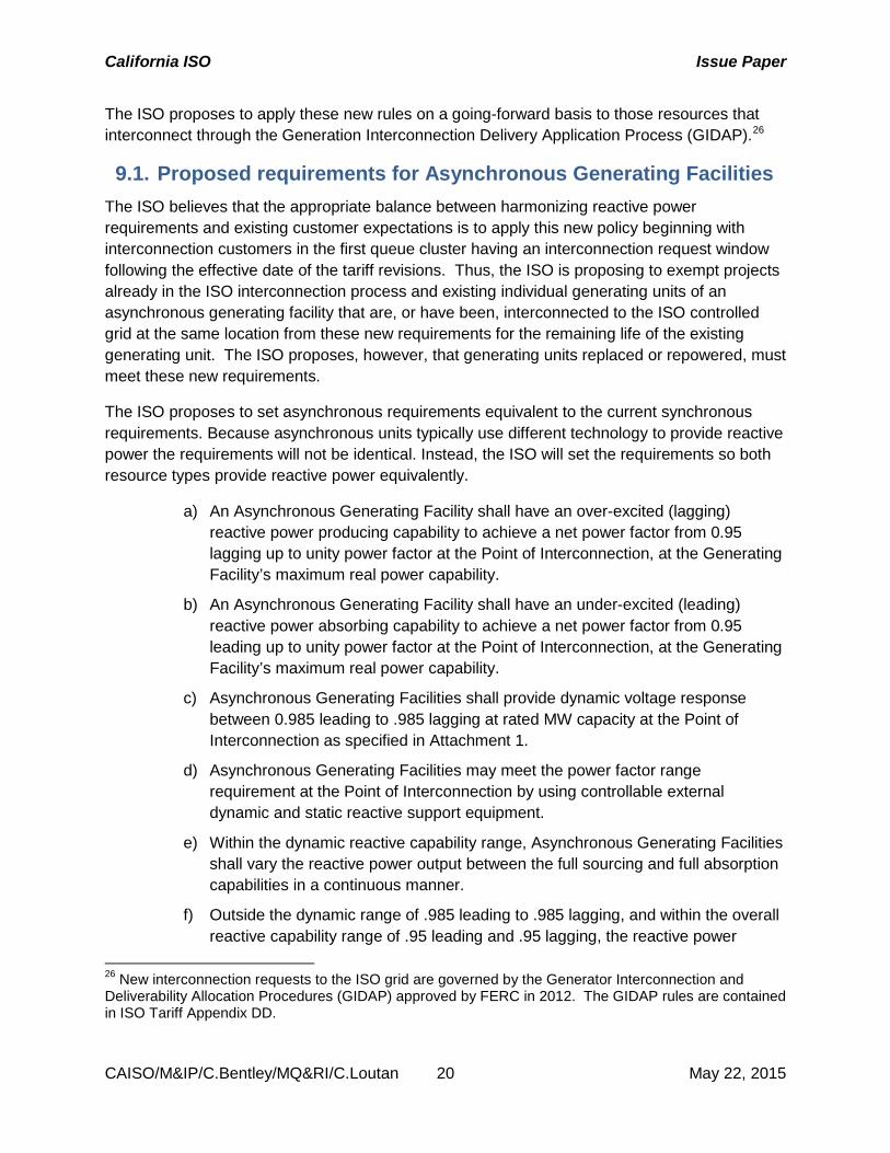
9.1. Proposed requirements for Asynchronous Generating Facilities The ISO believes that the appropriate balance between harmonizing reactive power requirements and existing customer expectations is to apply this new policy beginning with interconnection customers in the first queue cluster having an interconnection request window following the effective date of the tariff revisions. Thus, the ISO is proposing to exempt projects already in the ISO interconnection process and existing individual generating units of an asynchronous generating facility that are, or have been, interconnected to the ISO controlled grid at the same location from these new requirements for the remaining life of the existing generating unit. The ISO proposes, however, that generating units replaced or repowered, must meet these new requirements.
The ISO proposes to set asynchronous requirements equivalent to the current synchronous requirements. Because asynchronous units typically use different technology to provide reactive power the requirements will not be identical. Instead, the ISO will set the requirements so both resource types provide reactive power equivalently.
a) An Asynchronous Generating Facility shall have an over-excited (lagging) reactive power producing capability to achieve a net power factor from 0.95 lagging up to unity power factor at the Point of Interconnection, at the Generating Facility’s maximum real power capability.
b) An Asynchronous Generating Facility shall have an under-excited (leading) reactive power absorbing capability to achieve a net power factor from 0.95 leading up to unity power factor at the Point of Interconnection, at the Generating Facility’s maximum real power capability.
c) Asynchronous Generating Facilities shall provide dynamic voltage response between 0.985 leading to .985 lagging at rated MW capacity at the Point of Interconnection as specified in Attachment 1.
d) Asynchronous Generating Facilities may meet the power factor range requirement at the Point of Interconnection by using controllable external dynamic and static reactive support equipment.
e) Within the dynamic reactive capability range, Asynchronous Generating Facilities shall vary the reactive power output between the full sourcing and full absorption capabilities in a continuous manner.
f) Outside the dynamic range of .985 leading to .985 lagging, and within the overall reactive capability range of .95 leading and .95 lagging, the reactive power
26 New interconnection requests to the ISO grid are governed by the Generator Interconnection and Deliverability Allocation Procedures (GIDAP) approved by FERC in 2012. The GIDAP rules are contained in ISO Tariff Appendix DD.
California ISO Issue Paper
CAISO/M&IP/C.Bentley/MQ&RI/C.Loutan 21 May 22, 2015
capability could be met at full real power capability with controllable external static or dynamic reactive support equipment.
g) Should the interconnection studies show the need for dynamic reactive power within the overall reactive capability range of .95 leading to .95 lagging, then the full power factor range must be dynamic.
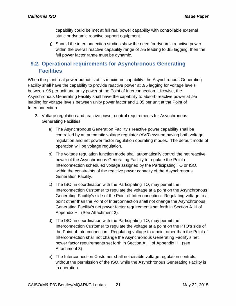
9.2. Operational requirements for Asynchronous Generating Facilities
When the plant real power output is at its maximum capability, the Asynchronous Generating Facility shall have the capability to provide reactive power at .95 lagging for voltage levels between .95 per unit and unity power at the Point of Interconnection. Likewise, the Asynchronous Generating Facility shall have the capability to absorb reactive power at .95 leading for voltage levels between unity power factor and 1.05 per unit at the Point of Interconnection.
2. Voltage regulation and reactive power control requirements for Asynchronous Generating Facilities:
a) The Asynchronous Generation Facility’s reactive power capability shall be controlled by an automatic voltage regulator (AVR) system having both voltage regulation and net power factor regulation operating modes. The default mode of operation will be voltage regulation.
b) The voltage regulation function mode shall automatically control the net reactive power of the Asynchronous Generating Facility to regulate the Point of Interconnection scheduled voltage assigned by the Participating TO or ISO, within the constraints of the reactive power capacity of the Asynchronous Generation Facility.
c) The ISO, in coordination with the Participating TO, may permit the Interconnection Customer to regulate the voltage at a point on the Asynchronous Generating Facility’s side of the Point of Interconnection. Regulating voltage to a point other than the Point of Interconnection shall not change the Asynchronous Generating Facility’s net power factor requirements set forth in Section A. iii of Appendix H. (See Attachment 3).
d) The ISO, in coordination with the Participating TO, may permit the Interconnection Customer to regulate the voltage at a point on the PTO’s side of the Point of Interconnection. Regulating voltage to a point other than the Point of Interconnection shall not change the Asynchronous Generating Facility’s net power factor requirements set forth in Section A. iii of Appendix H. (see Attachment 3)
e) The Interconnection Customer shall not disable voltage regulation controls, without the permission of the ISO, while the Asynchronous Generating Facility is in operation.
California ISO Issue Paper
CAISO/M&IP/C.Bentley/MQ&RI/C.Loutan 22 May 22, 2015
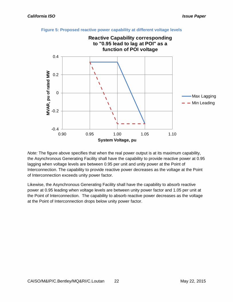
Figure 5: Proposed reactive power capability at different voltage levels
Note: The figure above specifies that when the real power output is at its maximum capability, the Asynchronous Generating Facility shall have the capability to provide reactive power at 0.95 lagging when voltage levels are between 0.95 per unit and unity power at the Point of Interconnection. The capability to provide reactive power decreases as the voltage at the Point of Interconnection exceeds unity power factor.
Likewise, the Asynchronous Generating Facility shall have the capability to absorb reactive power at 0.95 leading when voltage levels are between unity power factor and 1.05 per unit at the Point of Interconnection. The capability to absorb reactive power decreases as the voltage at the Point of Interconnection drops below unity power factor.
-0.4
-0.2
0
0.2
0.4
0.90 0.95 1.00 1.05 1.10
MVA
R, p
u of
rate
d M
W
System Voltage, pu
Reactive Capability correspondingto "0.95 lead to lag at POI" as a
function of POI voltage
Max LaggingMin Leading
California ISO Issue Paper
CAISO/M&IP/C.Bentley/MQ&RI/C.Loutan 23 May 22, 2015
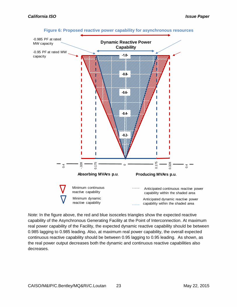
Figure 6: Proposed reactive power capability for asynchronous resources
Note: In the figure above, the red and blue isosceles triangles show the expected reactive capability of the Asynchronous Generating Facility at the Point of Interconnection. At maximum real power capability of the Facility, the expected dynamic reactive capability should be between 0.985 lagging to 0.985 leading. Also, at maximum real power capability, the overall expected continuous reactive capability should be between 0.95 lagging to 0.95 leading. As shown, as the real power output decreases both the dynamic and continuous reactive capabilities also decreases.
Dynamic Reactive PowerCapability
0.4
0.17
5 0
-.328
0.32
8
0.4
Absorbing MVArs p.u. Producing MVArs p.u.
Minimum continuousreactive capability
Minimum dynamicreactive capability
Anticipated continuous reactive powercapability within the shaded area
Anticipated dynamic reactive powercapability within the shaded area
-0.985 PF at rated MW capacity
-0.95 PF at rated MW capacity
0.17
5
-0.6-
-0.4-
-0.8-
-1.0-
-0.2-
California ISO Issue Paper
CAISO/M&IP/C.Bentley/MQ&RI/C.Loutan 24 May 22, 2015
10. Uniform requirement technical issues
10.1. Hunting Multiple asynchronous resources in close electrical proximity can cause unstable voltage control when their controls are not coordinated. Uncoordinated voltage control can also surface when two or more asynchronous resources share a common generation tie and are assigned to regulate voltage at a common Point of Interconnection. The ISO’s proposal should mitigate this concern by allowing asynchronous resources to control its terminal voltage. The ISO has also proposed to allow developers the flexibility to develop a control scheme to utilize a voltage droop function with necessary supervisory control to allow reactive power sharing among the asynchronous resources.
Last, the ISO has also proposed that developers can work together and elect to control the schedule voltage at a common station beyond the Point of Interconnection with other plant-level reactive support equipment.
10.2. Collective generation projects Many asynchronous resources comprise multiple devices aggregated for production at the wholesale level. The ISO proposes a uniform interconnection requirement to ensure the availability of sufficient and usable reactive capability in the operations horizon. Under the proposed reactive power requirements each resource must meet a power factor of 0.95 leading and lagging at or near the Point of Interconnection. Asynchronous resources may use a variety of means to meet this requirement, such as oversizing inverters, or using fast switching devices. The ISO will not discriminate based on technology aggregated within the participating resource. If all individual devices comprising an aggregated resource can meet this reactive requirement under the same participating resource, then the resources can participate in the market in any way it prefers. If the aggregated resource depends upon devices or sub-parts of the combined resource to meet this requirement, it must be dispatched under a single Resource ID in the market.
The ISO proposes to allow any collective generation project to participate in the market however it sees fit, provided that the resource can fully meet this requirement thus ensuring visibility, reliability, and availability of the reactive capability in the operations horizon. This proposal should serve as a universal planning requirement that ensures the availability of sufficient reactive capability in the operations horizon. Allowing a resource to participate in the market without this capability circumvents this process and creates the possibility of a generation dispatch and power transfer scenario in the operations horizon not reviewed via the planning process. Further any reactive power capacity payment made to a resource that can schedule or bid parts of the resource which do not meet the requirement circumvents the reactive capability the payment is meant to procure.
California ISO Issue Paper
CAISO/M&IP/C.Bentley/MQ&RI/C.Loutan 25 May 22, 2015
10.3. Metering and telemetry All resources participating in ISO markets must execute a meter service agreement and have ISO meters. There are no exemptions for size or unit type. The Metering BPM, appendix B, outlines technical specifications required for these meters. These include reactive power metering requirements.
Generating Units connected to the electric grid within the ISO balancing authority area (BAA) must install telemetry equipment and/or software that can interface with the ISO’s Energy Management System (EMS) to supply telemetered real-time data
These rules apply to all resources that:
(1) have a capacity of ten MW or greater, or
(2) provide Ancillary Services, or
(3) are Eligible Intermittent Resources
The BPM for telemetry defines reactive power telemetry requirements. Resources must provide MVAR value at the point of delivery (POD/POI) - where the unit connects to the ISO controlled grid. POD MVAR establishes reactive power delivery to the system and the impact on system voltage. This value may be obtained by installing instrument devices at or on the unit side of the POD. It can be calculated by providing an accurate conversion of another data point measured at the same voltage level as the POD. The value must represent an accuracy of +/-2% of the true value of POD MVAR represented in the ISO revenue meter.
10.4. Inverter size During the Interconnection Request (IR) validation process, the ISO validates that the generating resources net MW equal gross MW minus auxiliary load. The gross MW is the total installed capacity of the inverters. When inverters are used to provide reactive power, we ask the interconnection customer to note that the gross MW is a lower number than nameplate MW, which is at unity power factor.
Item 2A27 of the Interconnection Request asks for the Total Generating Facility rated output (MW) that represents the gross output number at the generator terminals. Typically, the inverter MW capacity provided by the manufacture is under the unity power factor. The MW capacity under a different power factor is lower than that under the unity power factor. If the Interconnection Customer uses inverters to meet the reactive power capability requirement, the ISO requests that the MW capacity and the associated power factor is indicated on the form.
The ISO proposes that we explicitly change the Interconnection Request form to include both MVA rating and MW rating for inverter based generators for ease of compliance verification.
27 https://www.caiso.com/Documents/SampleInterconnectionRequest-TechnicalData-Solar-Wind.pdf
California ISO Issue Paper
CAISO/M&IP/C.Bentley/MQ&RI/C.Loutan 26 May 22, 2015
The Generator Management BPM, section 3.5.4.1, describes how the ISO evaluates inverter changes that would cause a capacity increase greater than the project net capacity listed in the Interconnection Customer’s interconnection request. However, at no time may the Generating Facility’s inverter configuration increase the project’s net capacity by more than the greater of:
• ten percent (10%); or
• three (3) MW
One stakeholder submitted a comment appearing to express concerns that this limitation would prohibit a generation project from meeting the 0.95 lead/lag reactive power requirement if a resource voluntarily provided reactive power. During the stakeholder meeting the ISO explained that a generator that increased its inverter capacity by 5.2% could improve its power factor capability from a 1.0 power factor to a 0.95 lead/lag power factor, which is within the 10% limit.
10.5. Inverter cost The cost of including reactive power capability as a percentage of project costs is relatively small.28 Some entities contest this fact and argue that applying a uniform reactive power requirement to asynchronous resources creates significant capital and operational costs.29
The ISO recognizes the possible concern that a uniform requirement for asynchronous resources to provide reactive power capability and voltage regulation could impose higher inverter costs on those projects that would otherwise avoid such requirements through the system impact study approach currently in use. In this context the ISO conducted outreach with inverter manufacturers such as General Electric and Siemens to learn more. The ISO found:
• Approximately 5 percent of total plant cost is attributable to inverters and associated equipment (e.g., transformer, controller). This is a sunk cost because all asynchronous resources must have inverters. Given the sunk costs, the incremental costs for adding reactive power capabilities are less.
• Reactive power capability is now a standard feature of inverters used in both wind and solar PV applications and there is no additional cost for reactive power capability. Typically, these inverters can provide 0.95 leading and lagging power factor at full real power output at the Point of Interconnection.
Based on these observations, the ISO believes the additional costs, if any, due to a uniform requirement would likely be de minimis.
28 Id. at 141:10-124:6. 29 See e.g. Comments of the American Wind Energy Association in response to the April 22, 2014 workshop on Third Party Provision of Reactive Supply and Voltage Control and Regulation and Frequency Response Services filed in FERC Docket AD 14-7 at 7-8. http://elibrary.ferc.gov/idmws/common/opennat.asp?fileID=13567273
California ISO Issue Paper
CAISO/M&IP/C.Bentley/MQ&RI/C.Loutan 27 May 22, 2015
11. Financial compensation
11.1. Purpose Reactive power compensation recognizes that market resources providing reactive power have costs solely related to the fixed and variable costs of providing reactive power and therefore are inappropriate to recover through capacity and energy payments for real power. 30 FERC has accepted in other ISOs that these payments are just and reasonable; however, has required that these payments be based on the cost of providing reactive power. The ISO proposes to allow the recovery of generator-specific or technology-specific costs in conjunction with requiring equivalent reactive power requirements for all interconnected resources.
11.2. Regulatory Review Many ISO/RTOs provide financial compensation for the capability and/or provision of reactive power; however the payments and cost recovery methods vary by region. Payments for reactive power are similar to real power in that there are typically two potential revenue streams. The first is a capability payment. This is a payment for a resource having the capability to provide reactive power and should cover fixed costs. The second is a payment for the provision of reactive power and should cover marginal costs. These are roughly equivalent to capacity and energy payments for real power in some markets.
The main difference between reactive and real power from a financial compensation perspective is that reactive power is highly localized. A competitive market for reactive power would have extreme market power concerns to such an extent that marginal cost reactive power pricing would be infeasible. Instead, most regions (including the ISO) provide a resource-specific opportunity cost payment for reactive power that reflects any opportunity costs of not providing real power. Appendix A in section 13 describes approaches by other ISO/RTOs to address the recovery of fixed costs associated with reactive power capability and the variable costs of providing or absorbing reactive power.31
11.3. Compensation options The ISO is considering providing a two-part mechanism for financial compensation for the capability and provision of reactive power. First, the ISO proposes to update opportunities for resources to receive opportunity cost when providing reactive power outside the standard .95 lagging/leading requirements. Second, the ISO is considering a capability payment, similar to a capacity payment for real power, which would allow a resource capable of providing reactive
30 Market resources as distinguished from transmission assets or resources under RMR contracts as described in section 5. 31 See Appendix 3 to FERC Staff Report: Payment for Reactive Power in AD14-7 dated April 22, 2014. http://www.ferc.gov/CalendarFiles/20140414101009-04-11-14-reactive-power.pdf
California ISO Issue Paper
CAISO/M&IP/C.Bentley/MQ&RI/C.Loutan 28 May 22, 2015
power to recover all incremental costs associated with the provision of reactive power distinct from the provision of real power.
Capability payment 11.3.1.A capability payment is for the ability of the resource to operate within the .95 leading/lagging standard. FERC has found that compensation should not be based on the total quantity of reactive power a unit produces or the number of hours its reactive power capability is available.32 Therefore a capability payment is solely based on the capability of a unit to produce reactive power within a defined standard.
There are two primary methods the ISO is considering for determining a reactive power capability payment. First, the ISO could utilize the AEP method.33 The AEP method is a FERC-approved method of breaking out the components of a generating unit into components needed for real power and components needed for reactive power. The AEP method currently only applies to synchronous generation and would need to be expanded to include asynchronous generation. AEP identified three components of a generation plant for reactive power production:
• Generator and its exciter • Accessory electric equipment that supports the operation of the generator-exciter • The remaining total production investment required to provide real power and operate
the exciter
The annual revenue requirements of these items are then allocated into real and reactive power buckets. The current approved allocation factor is MVAr2/MVA2, where MVAr is the megavolt amperes reactive capability and the MVA is the megavolt amperes capability at a power factor of 1.
Generators use actual costs data, either in their FERC Form 1 data or independent data, to justify these costs at FERC. The inputs are rarely disputed; however, in those circumstances the dispute is generally settled before a FERC administrative law judge.
Using this methodology ISO would determine the monthly rate paid to an eligible interconnected generator by calculating its total annual revenue requirement for reactive power as determined by the AEP method and dividing by 12. The ISO would allocate these costs based on the ISO’s cost allocation principles as discussed in section 11.5.
If the ISO used the AEP method, it would have to be expanded to include asynchronous resources. One possibility would be to use a similar formula for reactive power costs and compare the cost of inverters/capacitors to meet the requirement against the cost to produce at the power factor of 1. Therefore the identified component for asynchronous resources would be:
• Inverter • Capacitor
32 See, e.g., Bluegrass Generation Company, L.L.C, 121 FERC 61,018, at pg13 (2007) (Bluegrass) 33 American Electric Power Service Corp, Opinion No. 440, 88 FERC 61,141 (1999) (AEP)
California ISO Issue Paper
CAISO/M&IP/C.Bentley/MQ&RI/C.Loutan 29 May 22, 2015
• Accessory electric equipment that supports the operation of the inverter or capacitor • The remaining total production investment required to provide real power and operate
the inverters and/or capacitors
The annual revenue requirements of these items would then be allocated similarly to the exiting AEP methodology and go into real and reactive power buckets. It would use the approved synchronous allocation factor is MVAr2/MVA2, where MVAr is the megavolt amperes reactive capability and the MVA is the megavolt amperes capability at a power factor of 1.
An additional enhancement to the AEP methodology could be to allow the cost recovery of fixed costs required for resources to install a “clutch” or the ability for the resource to move between providing real power and reactive power to only reactive power.
A second method the ISO could utilize was suggested in a Payment for Reactive Power Commission Staff Report.34 The ISO could request that the Commission use its acquired knowledge of reactive power generator specific costs that have been found just and reasonable for the past 20 years and establish acceptable ranges of acceptable allocators for any thermal generation type. They could produce a spreadsheet and the ISO could rely on these values to recreate a “safe harbor” value that generators could recover without filing at FERC. Any costs above their generation-specific safe harbor value resources could use the approved AEP methodology. The ISO would have to propose an addition to the AEP methodology for wind and solar resources; however, and additionally a “safe harbor” value for asynchronous resources would likely take the commission several years to develop as it acquired additional cost information.
The ISO seeks feedback on these two capability payment options.
Reactive power provision payment 11.3.2.The ISO already has rules for the provision of reactive power. The ISO has a mechanism to pay resources for reactive power dispatched outside the standard range required by the tariff. Tariff section 8.2.3.3 states that if the ISO requires additional Voltage Support, the ISO will instruct the resource to move its MVAR output outside its mandatory range. Only if the resource must reduce its MW output to comply with such an instruction will it be eligible to recover its opportunity cost under Section 11.10.1.4.
Section 11.10.1.4 specifies that the total payments for Voltage Support in any shall be the sum of the opportunity costs of limiting energy output to enable reactive energy production in response to an ISO instruction. The opportunity cost is calculated based on the product of the energy amount that would have cleared the market at the price of the Resource-Specific Settlement Interval LMP minus the higher of the Energy Bid price or the Default Energy Bid price.
Scheduling Coordinators for resources providing reactive power still receive any payments under any long-term contracts even if they also receive an opportunity cost payments.
34 http://www.ferc.gov/legal/staff-reports/2014/04-11-14-reactive-power.pdf
California ISO Issue Paper
CAISO/M&IP/C.Bentley/MQ&RI/C.Loutan 30 May 22, 2015
Exceptional Dispatches for incremental or decremental energy needed for Voltage Support procured through Exceptional Dispatch is paid and settled under Sections 11.5.6.1. RMR Units providing Voltage Support are compensated under the RMR Contract rather than this Section 11.10.1.4.
These rules may need to be enhanced and the ISO seeks comments on whether the current opportunity cost payment is still appropriate.
Additionally, the ISO may consider additional provision payments and a new exceptional dispatch category for resources that are able to switch between providing real power and reactive power very quickly. These resources would only provide reactive power if they were not picked up in the market optimization, but were still needed for reactive power. It may be appropriate to compensate these resources for their variable reactive power costs – O&M and energy costs to provide reactive power- through a different mechanism than the capability payment. These resources would not have an opportunity cost because they are “out of the money” in the energy market optimization, but still are providing a service to the ISO. The ISO seeks comment on the appropriate mechanism, if any, to allow these resources to recover their variable costs.
11.4. Compliance and testing The ISO currently has the tariff authority to test whether a resource can provide voltage support. Section 8.9.4.1 allows the ISO to test the voltage support capability of a resource by issuing unannounced dispatch instructions requiring the resource to adjust its power factor outside the specified power factor band of 0.90 lag to 0.95 lead, but within the limits of the resource capability curve. Section 8.9.4.2 allows the ISO to test the voltage support capability of other reactive devices, such as shunt capacitors, static var compensators, and synchronous condensers) by issuing unannounced dispatch instructions to these devices.
While the ISO may test for compliance there is no immediate financial impact if a resource is out of compliance. Once the financial mechanism is established, the ISO could establish a mechanism to take back any capability payments if a resource fails a voltage support test. The ISO seeks comments from stakeholders on whether compliance and testing should be directly linked to financial compensation.
11.5. Cost allocation The ISO briefed the Board of Governors on cost allocation guiding principles at the May 2012 board meeting. The cost allocation guiding principles have seven elements: (1) Causation, (2) Comparable Treatment, (3) Efficient Policy Achievement, (4) Incentivize Behavior, (5)
California ISO Issue Paper
CAISO/M&IP/C.Bentley/MQ&RI/C.Loutan 31 May 22, 2015
Manageable, (6) Synchronized, and (7) Rational.35 These principles were established to guide any future cost allocation market design.
Given these principles, the ISO believes it makes sense to explore separate cost allocations for each payment mechanism. Therefore costs associated from the capability payment and the provision payment will likely have different cost allocations.
11.6. Other compensation issues One question that arose out of the technical working group was whether an existing asynchronous resource without a reactive power requirement could voluntarily take on the requirement to qualify for financial compensation. Given this is a small set of resources that will phase out over time due to the repowering requirement, the ISO does not believe that it is necessary to create special rules for a small set of resources. However, the ISO would like to hear additional feedback from parties that would want to voluntarily meet the reactive power requirement and how they envision the verification and process of voluntary reactive power provision may work.
12. Next Steps
The ISO will discuss this issue paper with stakeholders during a call on May 28, 2015. Stakeholders should submit written comments by June 11, 2015 to [email protected].
35 http://www.caiso.com/informed/Pages/StakeholderProcesses/CompletedStakeholderProcesses/CostAllocationGuidingPrinciples.aspx
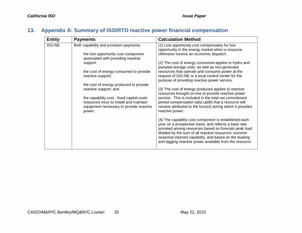
California ISO Issue Paper
CAISO/M&IP/C.Bentley/MQ&RI/C.Loutan 32 May 22, 2015
13. Appendix A: Summary of ISO/RTO reactive power financial compensation Entity Payments Calculation Method ISO-NE Both capability and provision payments.
the lost opportunity cost component
associated with providing reactive support
the cost of energy consumed to provide
reactive support;
the cost of energy produced to provide reactive support; and
the capability cost - fixed capital costs
resources incur to install and maintain equipment necessary to provide reactive power.
(1) Lost opportunity cost compensates for lost opportunity in the energy market when a resource otherwise receive an economic dispatch. (2) The cost of energy consumed applies to hydro and pumped storage units, as well as non-generator resources that operate and consume power at the request of ISO-NE or a local control center for the purpose of providing reactive power service. (3) The cost of energy produced applies to reactive resources brought on-line to provide reactive power service. This is included in the total net commitment period compensation (aka uplift) that a resource will receive attributed to the hour(s) during which it provides reactive power. (4) The capability cost component is established each year on a prospective basis, and reflects a base rate prorated among resources based on forecast peak load divided by the sum of all reactive resources’ summer seasonal claimed capability, and based on the leading and lagging reactive power available from the resource.
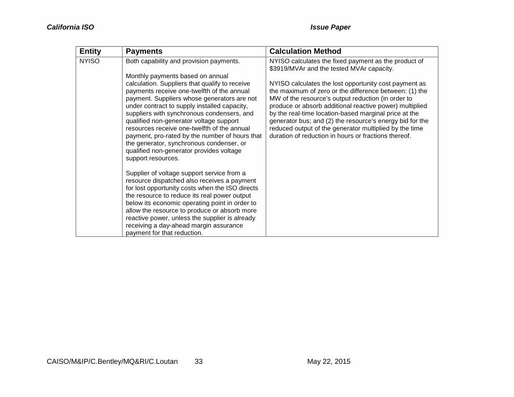
California ISO Issue Paper
CAISO/M&IP/C.Bentley/MQ&RI/C.Loutan 33 May 22, 2015
Entity Payments Calculation Method NYISO Both capability and provision payments.
Monthly payments based on annual calculation. Suppliers that qualify to receive payments receive one-twelfth of the annual payment. Suppliers whose generators are not under contract to supply installed capacity, suppliers with synchronous condensers, and qualified non-generator voltage support resources receive one-twelfth of the annual payment, pro-rated by the number of hours that the generator, synchronous condenser, or qualified non-generator provides voltage support resources. Supplier of voltage support service from a resource dispatched also receives a payment for lost opportunity costs when the ISO directs the resource to reduce its real power output below its economic operating point in order to allow the resource to produce or absorb more reactive power, unless the supplier is already receiving a day-ahead margin assurance payment for that reduction.
NYISO calculates the fixed payment as the product of $3919/MVAr and the tested MVAr capacity. NYISO calculates the lost opportunity cost payment as the maximum of zero or the difference between: (1) the MW of the resource’s output reduction (in order to produce or absorb additional reactive power) multiplied by the real-time location-based marginal price at the generator bus; and (2) the resource’s energy bid for the reduced output of the generator multiplied by the time duration of reduction in hours or fractions thereof.
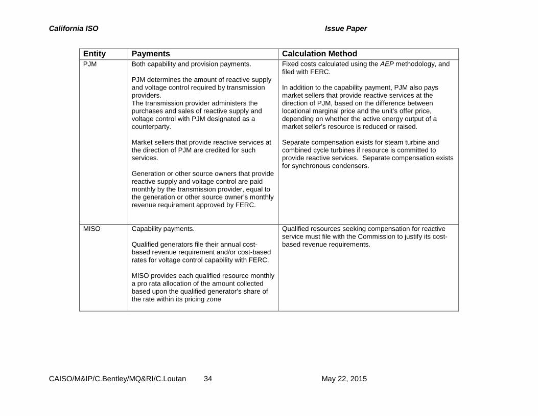
California ISO Issue Paper
CAISO/M&IP/C.Bentley/MQ&RI/C.Loutan 34 May 22, 2015
Entity Payments Calculation Method PJM Both capability and provision payments.
PJM determines the amount of reactive supply and voltage control required by transmission providers. The transmission provider administers the purchases and sales of reactive supply and voltage control with PJM designated as a counterparty. Market sellers that provide reactive services at the direction of PJM are credited for such services. Generation or other source owners that provide reactive supply and voltage control are paid monthly by the transmission provider, equal to the generation or other source owner’s monthly revenue requirement approved by FERC.
Fixed costs calculated using the AEP methodology, and filed with FERC. In addition to the capability payment, PJM also pays market sellers that provide reactive services at the direction of PJM, based on the difference between locational marginal price and the unit’s offer price, depending on whether the active energy output of a market seller’s resource is reduced or raised. Separate compensation exists for steam turbine and combined cycle turbines if resource is committed to provide reactive services. Separate compensation exists for synchronous condensers.
MISO Capability payments. Qualified generators file their annual cost-based revenue requirement and/or cost-based rates for voltage control capability with FERC. MISO provides each qualified resource monthly a pro rata allocation of the amount collected based upon the qualified generator’s share of the rate within its pricing zone
Qualified resources seeking compensation for reactive service must file with the Commission to justify its cost-based revenue requirements.
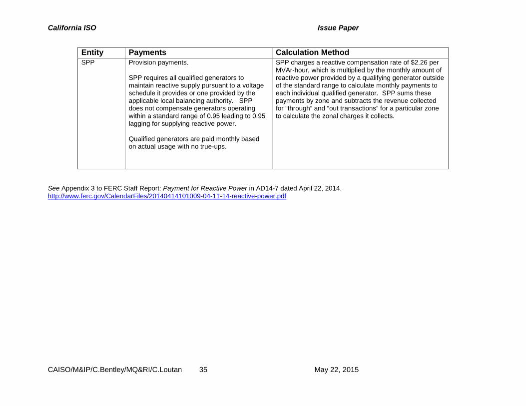
California ISO Issue Paper
CAISO/M&IP/C.Bentley/MQ&RI/C.Loutan 35 May 22, 2015
Entity Payments Calculation Method SPP Provision payments.
SPP requires all qualified generators to maintain reactive supply pursuant to a voltage schedule it provides or one provided by the applicable local balancing authority. SPP does not compensate generators operating within a standard range of 0.95 leading to 0.95 lagging for supplying reactive power. Qualified generators are paid monthly based on actual usage with no true-ups.
SPP charges a reactive compensation rate of $2.26 per MVAr-hour, which is multiplied by the monthly amount of reactive power provided by a qualifying generator outside of the standard range to calculate monthly payments to each individual qualified generator. SPP sums these payments by zone and subtracts the revenue collected for “through” and “out transactions” for a particular zone to calculate the zonal charges it collects.
See Appendix 3 to FERC Staff Report: Payment for Reactive Power in AD14-7 dated April 22, 2014. http://www.ferc.gov/CalendarFiles/20140414101009-04-11-14-reactive-power.pdf


![Reactive Power Compensation[1]](https://static.documents.pub/doc/80x56/577ccf3f1a28ab9e788f40c0/reactive-power-compensation1.jpg)


