32
REACTO-EN - User Manual STATORIC STARTING PANEL FOR ELECTRIC PUMP - STANDARD EN 12845 -

REACTO-EN - User Manual
STATORIC STARTING PANEL FOR ELECTRIC PUMP
- STANDARD EN 12845 -

III
CONTENTS
1. INTRODUCTION ...................................................................................................... 5
2. WARNINGS ............................................................................................................ 6
3. GENERAL DESCRIPTION .......................................................................................... 7
4. INSTALLATION ........................................................................................................ 8
4.1 Electrical power line: .......................................................................................... 9
4.2 External command lines ..................................................................................... 9
5. OPERATION .......................................................................................................... 10
5.1 Automatic mode ............................................................................................... 10
5.2 Manual mode ................................................................................................... 10
5.3 Emergency mode .............................................................................................. 11
5.4 Shutdown .......................................................................................................... 11
6. LUMINOUS INDICATORS AND BUTTONS .............................................................. 12
7. ALARMS ............................................................................................................... 13
8. AUTOMATIC CALIBRATION................................................................................... 14
9. OPTIONAL PROGRAMMING ................................................................................. 15
9.1 Motor in operation ........................................................................................... 15
9.2 Start-up failure ................................................................................................. 16
9.3 Start-up failure controlled by the pump pressure switch ................................. 16
9.4 Mains underfrequency ...................................................................................... 17
9.5 Mains overfrequency ........................................................................................ 17
9.6 Mains undervoltage .......................................................................................... 18
9.7 Mains voltage present ...................................................................................... 18
9.8 Mains overvoltage ............................................................................................ 19
9.9 Pump overcurrent ............................................................................................. 19
IV
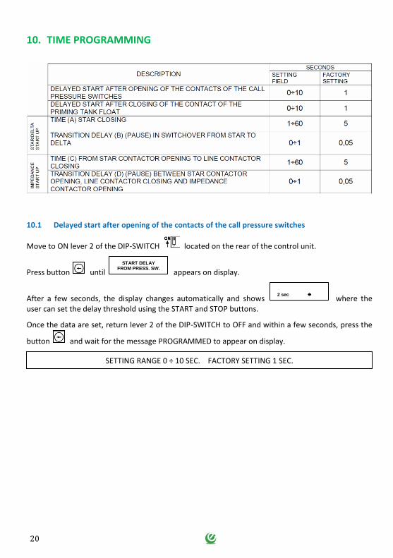
10. TIME PROGRAMMING ..................................................................................... 20
10.1 Delayed start after opening of the contacts of the call pressure switches ....... 20
10.2 Delayed start after closing of the contact of the priming tank float ................ 21
11. SETTINGS MADE .............................................................................................. 22
11.1 Pump overcurrent ............................................................................................. 22
11.2 Pump pressure switch function activation ........................................................ 22
12. ENABLING AUTOMATIC SHUTDOWN ACCORDING TO UNI-10779 .................... 23
13. LANGUAGE SELECTION ..................................................................................... 24
14. AUXILIARY FUNCTIONS .................................................................................... 24
15. PARTIAL HOUR COUNTER ................................................................................ 25
16. INSTRUMENT ENABLE/DISABLE ....................................................................... 25
17. RESTORING FACTORY SETTINGS ....................................................................... 25
18. GENERAL CONDITIONS ..................................................................................... 26
18.1 Warranty .......................................................................................................... 26
18.2 Maintenance..................................................................................................... 26
18.3 Disposal ............................................................................................................ 26
19. DECLARATION OF CONFORMITY ...................................................................... 27
5
1. INTRODUCTION
This manual must always accompany the relevant equipment and be conserved in an accessible location for consultation by qualified technicians assigned for operation and maintenance of the system.
The installer/user is strongly recommended to carefully read all instructions and information in this manual before using the product, in order to avoid damage or improper use of the unit, which would also render the warranty null and void.
Before operating the equipment, carefully read the manual and follow all instructions provided.
The information and instructions in this manual refer to the standard use of this product; in the event of special circumstances, functions or applications not described in this document, contact our service center for assistance.
If technical assistance or spare parts are required, when contacting the manufacturer always specify the identification code of the model and construction number as stated on the data plate.
Our service center is available for any requirement or clarification.
On receipt of the goods, inspect immediately to ensure that the equipment has not been damaged during transport. If defects are found, the client should promptly notify our retailer within 5 days of receiving the goods, or in the event of direct purchases, the Elentek service center.
N.B. the information provided in this manual is subject to modifications without notice. The manufacturer shall not be held liable for any damage caused in relation to the use of these instructions, as they are to be considered guideline only. Note that failure to observe the instructions provided in this manual may cause physical injury or damage to objects.
In any event all local and/or current legislation must be observed at all times.
6
2. WARNINGS
The electrical panel must be used exclusively for the purpose and function as specified in design. Any other application or use is to be considered improper and therefore hazardous.
In the event of a fire in the place of installation or the surrounding area, avoid the use of water jets and use the appropriate extinguishing equipment and means (powder, foam, carbon dioxide).
Install the equipment far from heat sources and in a dry and sheltered location in observance of the stated protection rating (IP).
The installation of a safety device is recommended to protect the panel power line in compliance with current electrical standards.
The electrical panel must be connected by a qualified electrician in observance of the relevant electrical standards.
No parts of the panel must be disassembled without the official authorization of Elentek: any tampering with or modifications to the unit will render all terms of the warranty null and void.
All installation and/or maintenance operations must be performed by a specialized technician who is fully aware of the relevant current safety standards.
Ensure the installation is connected to an efficient earthing system.
After making the electrical connection, check that all electrical panel settings are correct to avoid automatic start-up of the electric pump.
Elentek declines all liability in the event of the following:
- Incorrect installation;
- Use by personnel not adequately trained in the correct use of the panel;
- Serious failure to perform scheduled maintenance;
- Use of non-original spare parts or parts not specific to the model;
- Unauthorized modifications or interventions;
- Partial or total failure to observe instructions.
7
3. GENERAL DESCRIPTION
Power supply 3 ~ 50/60Hz 400V±10%;
Low voltage control circuits and inputs;
2 normally closed inputs for control of the start-up pressure switches;
Input for command from priming tank;
Input for signal from pressure switch to indicate system under pressure/pump off;
AUTOMATIC -0-EMERGENCY key selector;
Start/Stop buttons for manual test;
Control unit led test button;
Control unit function menu button;
LCD display to show the mains voltage and amperes on 3 phases, Hz, var, watt, volt/amp,
cosfi, total and partial hour counter, event log;
Display with 5 languages: Italian, English, French, Spanish, German;
Indicator leds;
Option of operation compliant with UNI10779;
Settable delay and alarm functions;
Impedance exchange timer settable via control unit;
Alarm outputs for: availability of electrical power, pump start-up request, pump running,
start-up failure;
Electric pump contactors in AC4;
Protection of aux. circuits and motor with fuses;
Door lock main disconnect switch;
Metal enclosure (IP55);
Ambient temperature: -5/+40 °C;
Relative humidity 50% at 40 °C (condensate free).
8
4. INSTALLATION
Ensure that the mains power supply specifications correspond to the voltage specified on the data plate of the electrical panel and motor connected, then make the earthing connection before all other connections.
REACTO-EN ► 3~400V ± 10% 50/60Hz
The power line must be protected by a residual current circuit breaker.
Tighten the electrical cables on the relative terminals using a suitable tool correctly sized to avoid the risk of damage to the fixing screws. Take care if using an electric screwdriver.
The electrical panel is designed for wall-mounting using screws and plugs in the pre-drilled holes at the corners of the enclosure, or by means of brackets when present.
Install the equipment in areas compliant with the protection rating and ensure that the box is kept intact when drilling the holes for fitting the cable clamps.
Avoid the use of multicore cables where there are wires connected to inductive loads and power cables and signal cables such as sensors and digital inputs.
Keep connection cables as short as possible, preventing any twisting of cables which may be harmful due to inductive effects on the electronic equipment.
All wires used in the cabling must be suitably sized to withstand the load to be powered.
9
4.1 Electrical power line:
Make the earthing connection before all other connections.
Ensure that the mains voltage corresponds to the specifications on the electrical panel
data plate:
Ensure that the power cable is able to withstand 150% of the maximum motor current
(according to EN 12845 Par. 10.8.4) and connect it to the terminals of the main disconnect
switch of the electrical panel.
The line must be protected in compliance with current standards.
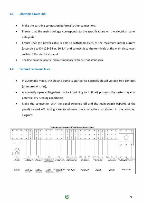
4.2 External command lines
In automatic mode, the electric pump is started via normally closed voltage-free contacts
(pressure switches);
A normally open voltage-free contact (priming tank float) protects the system against
potential dry running conditions;
Make the connection with the panel switched off and the main switch (UPLINE of the
panel) turned off, taking care to observe the connections as shown in the attached
diagram.
10
5. OPERATION
This device enables management in AUTOMATIC, MANUAL or EMERGENCY mode of an electrical pump in accordance with standards EN 12845.
When necessary, the electric pump is shut down automatically in a pumping system with exclusive use of the network of hydrants (as envisaged by standard UNI 10779 July 2007).
When the panel is switched on, the display is activated with a brief general check-up lasting a few seconds, after which the control unit displays the control parameters.
When the electrical panel is switched on, the system sets up for AUTOMATIC mode, and only when necessary can be set to MANUAL mode by pressing the START button.
The panel is equipped with an AUTOMATIC-EMERGENCY selector with key that can be removed in the AUTOMATIC position, to activate the following operating mode:
5.1 Automatic mode
With the key set to AUTOMATIC (the key is removable in this position); otherwise automatic start-up
is inhibited, as signalled by the flashing indicator (automatic start-up inhibited) and display of the message: AUT. START-UP INHIBITED. When the control unit detects opening of the starting contact (pressure switches), it starts up the electric pump. The control unit monitors (without stopping the pump) any faults on the motor during its operation. Automatic start-up occurs on opening of the contacts of the starting pressure switches; this is indicated by the steady indicator
light for start-up request from the pressure switches.
After any closure of the pressure switches, this indicator starts flashing.
Automatic start-up occurs also on closure of the contact of the pump priming float; this is indicated
by the steady indicator light . After opening of the contact, the indicator starts flashing. The flashing signals continue for the entire duration of motor operation.
5.2 Manual mode
To manually start up the electric pump (useful when testing the system), press the START button of the control unit, taking care that the AUTOMATIC-EMERGENCY selector is set to AUTOMATIC.
11
5.3 Emergency mode
The system envisages the option of manual start-up in EMERGENCY mode in the event of a fault on the electronic control unit or power supply system to the latter.
When the key is set to EMERGENCY, this immediately activates the electric pump control contactor (the motor is started up in DELTA mode) by-passing all electronic controls of the panel. This means that the operator will start up the pump.
5.4 Shutdown
The motor can only be shut down manually. It cannot be shut down when there is a request from pressure switches or automatic start-up is enabled.
If the pressure switch request is activated, even when the stop button is pressed, the electric pump does not shut down and the control unit display shows the message:
DO NOT SHUT DOWN IN THE EVENT OF FIRE - SHUTDOWN INHIBITED
If the pressure switch request is deactivated by pressing the STOP button, the electric pump shuts down and the control unit display shows the message:
DO NOT SHUT DOWN IN THE EVENT OF FIRE
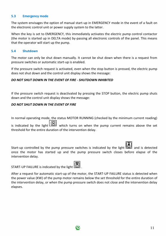
In normal operating mode, the status MOTOR RUNNING (checked by the minimum current reading)
is indicated by the light which turns on when the pump current remains above the set threshold for the entire duration of the intervention delay.
Start-up controlled by the pump pressure switches is indicated by the light and is detected once the motor has started up and the pump pressure switch closes before elapse of the intervention delay.
START-UP FAILURE is indicated by the light .
After a request for automatic start-up of the motor, the START-UP FAILURE status is detected when the power value (KW) of the pump motor remains below the set threshold for the entire duration of the intervention delay, or when the pump pressure switch does not close and the intervention delay elapses.
12
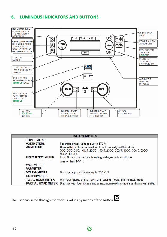
6. LUMINOUS INDICATORS AND BUTTONS
The user can scroll through the various values by means of the button .
13
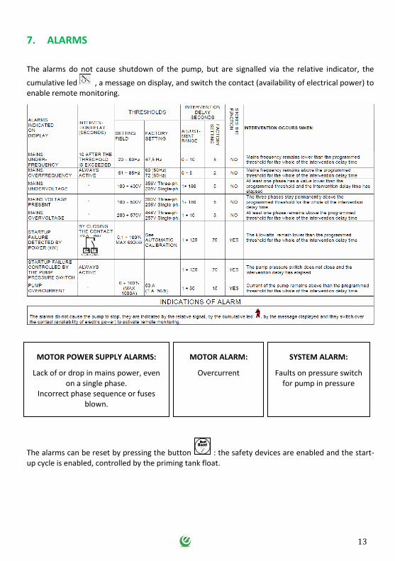
7. ALARMS
The alarms do not cause shutdown of the pump, but are signalled via the relative indicator, the
cumulative led , a message on display, and switch the contact (availability of electrical power) to enable remote monitoring.
The alarms can be reset by pressing the button : the safety devices are enabled and the start-up cycle is enabled, controlled by the priming tank float.
MOTOR POWER SUPPLY ALARMS:
Lack of or drop in mains power, even on a single phase.
Incorrect phase sequence or fuses blown.
MOTOR ALARM:
Overcurrent
SYSTEM ALARM:
Faults on pressure switch for pump in pressure
14
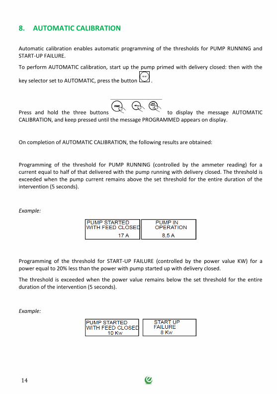
8. AUTOMATIC CALIBRATION
Automatic calibration enables automatic programming of the thresholds for PUMP RUNNING and START-UP FAILURE.
To perform AUTOMATIC calibration, start up the pump primed with delivery closed: then with the
key selector set to AUTOMATIC, press the button .
Press and hold the three buttons to display the message AUTOMATIC CALIBRATION, and keep pressed until the message PROGRAMMED appears on display.
On completion of AUTOMATIC CALIBRATION, the following results are obtained:
Programming of the threshold for PUMP RUNNING (controlled by the ammeter reading) for a current equal to half of that delivered with the pump running with delivery closed. The threshold is exceeded when the pump current remains above the set threshold for the entire duration of the intervention (5 seconds).
Example:
Programming of the threshold for START-UP FAILURE (controlled by the power value KW) for a power equal to 20% less than the power with pump started up with delivery closed.
The threshold is exceeded when the power value remains below the set threshold for the entire duration of the intervention (5 seconds).
Example:
15
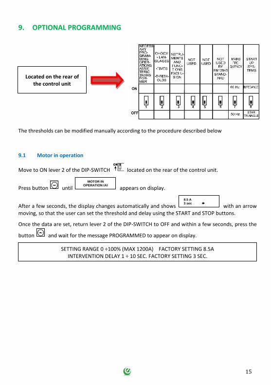
9. OPTIONAL PROGRAMMING
The thresholds can be modified manually according to the procedure described below
9.1 Motor in operation
Move to ON lever 2 of the DIP-SWITCH located on the rear of the control unit.
Press button until appears on display.
After a few seconds, the display changes automatically and shows with an arrow moving, so that the user can set the threshold and delay using the START and STOP buttons.
Once the data are set, return lever 2 of the DIP-SWITCH to OFF and within a few seconds, press the
button and wait for the message PROGRAMMED to appear on display.
MOTOR IN OPERATION (A)
8.5 A 3 sec
SETTING RANGE 0 ÷100% (MAX 1200A) FACTORY SETTING 8.5A INTERVENTION DELAY 1 ÷ 10 SEC. FACTORY SETTING 3 SEC.
Located on the rear of the control unit
16
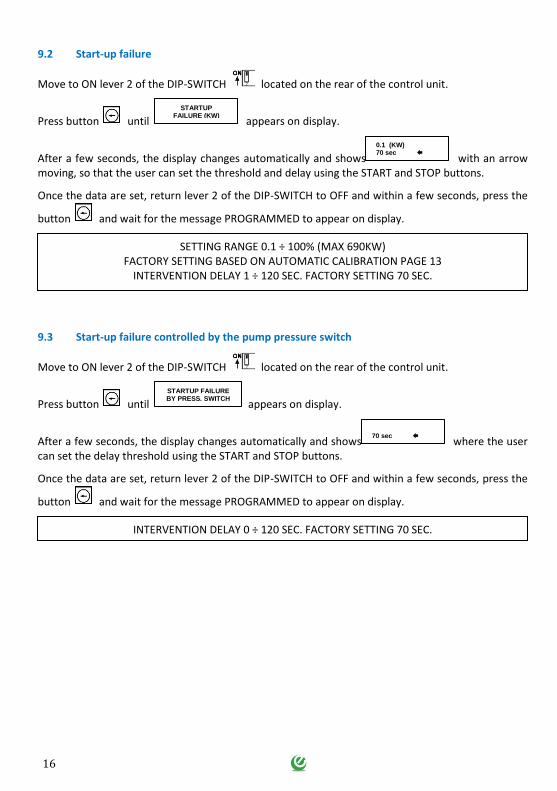
9.2 Start-up failure
Move to ON lever 2 of the DIP-SWITCH located on the rear of the control unit.
Press button until appears on display.
After a few seconds, the display changes automatically and shows with an arrow moving, so that the user can set the threshold and delay using the START and STOP buttons.
Once the data are set, return lever 2 of the DIP-SWITCH to OFF and within a few seconds, press the
button and wait for the message PROGRAMMED to appear on display.
9.3 Start-up failure controlled by the pump pressure switch
Move to ON lever 2 of the DIP-SWITCH located on the rear of the control unit.
Press button until appears on display.
After a few seconds, the display changes automatically and shows where the user can set the delay threshold using the START and STOP buttons.
Once the data are set, return lever 2 of the DIP-SWITCH to OFF and within a few seconds, press the
button and wait for the message PROGRAMMED to appear on display.
STARTUP FAILURE (KW)
0.1 (KW) 70 sec
SETTING RANGE 0.1 ÷ 100% (MAX 690KW) FACTORY SETTING BASED ON AUTOMATIC CALIBRATION PAGE 13
INTERVENTION DELAY 1 ÷ 120 SEC. FACTORY SETTING 70 SEC.
STARTUP FAILURE BY PRESS. SWITCH
70 sec
INTERVENTION DELAY 0 ÷ 120 SEC. FACTORY SETTING 70 SEC.

17
9.4 Mains underfrequency
Move to ON lever 2 of the DIP-SWITCH located on the rear of the control unit.
Press button until appears on display.
After a few seconds, the display changes automatically and shows with an arrow moving, so that the user can set the threshold and delay using the START and STOP buttons.
Once the data are set, return lever 2 of the DIP-SWITCH to OFF and within a few seconds, press the
button and wait for the message PROGRAMMED to appear on display.
9.5 Mains overfrequency
Move to ON lever 2 of the DIP-SWITCH located on the rear of the control unit.
Press button until appears on display.
After a few seconds, the display changes automatically and shows with an arrow moving, so that the user can set the threshold and delay using the START and STOP buttons.
Once the data are set, return lever 2 of the DIP-SWITCH to OFF and within a few seconds, press the
button and wait for the message PROGRAMMED to appear on display.
LINE MAIN UNDERFREQUENCY
46 Hz 2 sec
SETTING RANGE 20 - 60 Hz FACTORY SETTING 47.5 (50 Hz) 57 (60 Hz)
INTERVENTION DELAY 0 - 10 SEC. FACTORY SETTING 5 SEC.
LINE MAIN
OVERFREQUENCY
60 Hz 2 sec
SETTING RANGE 51 - 85 Hz FACTORY SETTING 60 (50 Hz) 72 (60 Hz)
INTERVENTION DELAY 0 - 5 SEC. FACTORY SETTING 2 SEC.
47.5 Hz
60 Hz
18
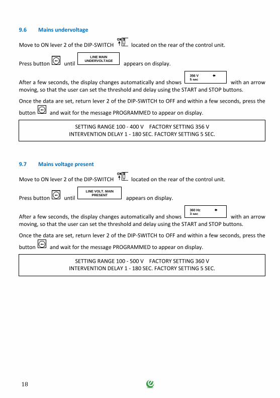
9.6 Mains undervoltage
Move to ON lever 2 of the DIP-SWITCH located on the rear of the control unit.
Press button until appears on display.
After a few seconds, the display changes automatically and shows with an arrow moving, so that the user can set the threshold and delay using the START and STOP buttons.
Once the data are set, return lever 2 of the DIP-SWITCH to OFF and within a few seconds, press the
button and wait for the message PROGRAMMED to appear on display.
9.7 Mains voltage present
Move to ON lever 2 of the DIP-SWITCH located on the rear of the control unit.
Press button until appears on display.
After a few seconds, the display changes automatically and shows with an arrow moving, so that the user can set the threshold and delay using the START and STOP buttons.
Once the data are set, return lever 2 of the DIP-SWITCH to OFF and within a few seconds, press the
button and wait for the message PROGRAMMED to appear on display.
LINE MAIN UNDERVOLTAGE
356 V 5 sec
SETTING RANGE 100 - 400 V FACTORY SETTING 356 V INTERVENTION DELAY 1 - 180 SEC. FACTORY SETTING 5 SEC.
LINE VOLT. MAIN PRESENT
360 Hz 3 sec
SETTING RANGE 100 - 500 V FACTORY SETTING 360 V INTERVENTION DELAY 1 - 180 SEC. FACTORY SETTING 5 SEC.
356 V
19
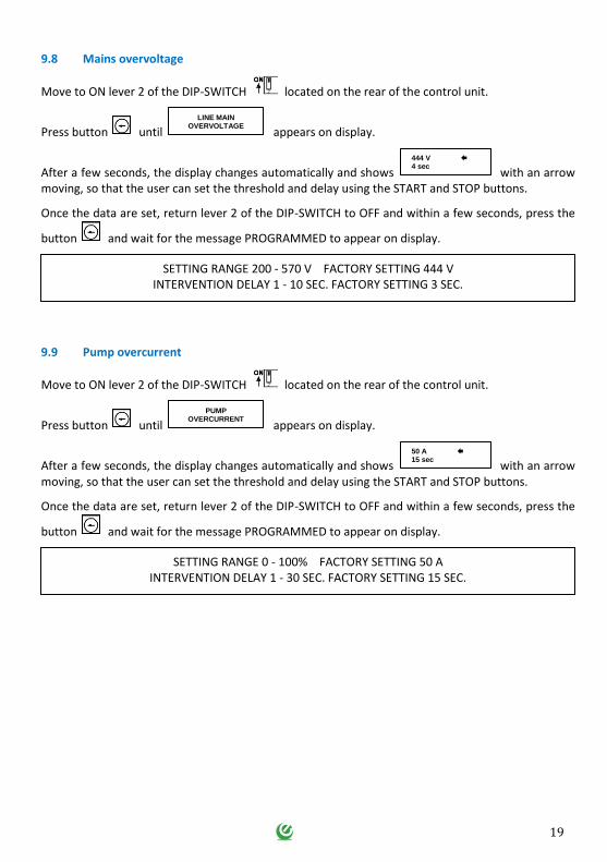
9.8 Mains overvoltage
Move to ON lever 2 of the DIP-SWITCH located on the rear of the control unit.
Press button until appears on display.
After a few seconds, the display changes automatically and shows with an arrow moving, so that the user can set the threshold and delay using the START and STOP buttons.
Once the data are set, return lever 2 of the DIP-SWITCH to OFF and within a few seconds, press the
button and wait for the message PROGRAMMED to appear on display.
9.9 Pump overcurrent
Move to ON lever 2 of the DIP-SWITCH located on the rear of the control unit.
Press button until appears on display.
After a few seconds, the display changes automatically and shows with an arrow moving, so that the user can set the threshold and delay using the START and STOP buttons.
Once the data are set, return lever 2 of the DIP-SWITCH to OFF and within a few seconds, press the
button and wait for the message PROGRAMMED to appear on display.
LINE MAIN OVERVOLTAGE
444 V 4 sec
SETTING RANGE 200 - 570 V FACTORY SETTING 444 V INTERVENTION DELAY 1 - 10 SEC. FACTORY SETTING 3 SEC.
PUMP OVERCURRENT
50 A 15 sec
SETTING RANGE 0 - 100% FACTORY SETTING 50 A INTERVENTION DELAY 1 - 30 SEC. FACTORY SETTING 15 SEC.
20
10. TIME PROGRAMMING
10.1 Delayed start after opening of the contacts of the call pressure switches
Move to ON lever 2 of the DIP-SWITCH located on the rear of the control unit.
Press button until appears on display.
After a few seconds, the display changes automatically and shows where the user can set the delay threshold using the START and STOP buttons.
Once the data are set, return lever 2 of the DIP-SWITCH to OFF and within a few seconds, press the
button and wait for the message PROGRAMMED to appear on display.
START DELAY FROM PRESS. SW.
2 sec
SETTING RANGE 0 ÷ 10 SEC. FACTORY SETTING 1 SEC.
21
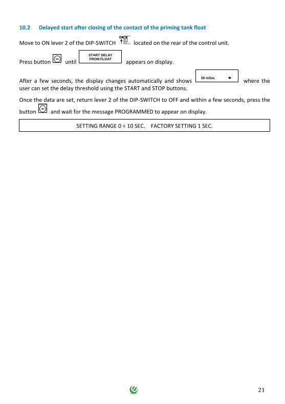
10.2 Delayed start after closing of the contact of the priming tank float
Move to ON lever 2 of the DIP-SWITCH located on the rear of the control unit.
Press button until appears on display.
After a few seconds, the display changes automatically and shows where the user can set the delay threshold using the START and STOP buttons.
Once the data are set, return lever 2 of the DIP-SWITCH to OFF and within a few seconds, press the
button and wait for the message PROGRAMMED to appear on display.
START DELAY FROM FLOAT
50 mSec
SETTING RANGE 0 ÷ 10 SEC. FACTORY SETTING 1 SEC.
22
11. SETTINGS MADE
11.1 Pump overcurrent
On the basis of the panel power, the amp and current transformers are selected and programmed accordingly.
The following amp transformer versions can be selected:
30/5, 40/5, 50/5, 60/5, 80/5, 100/5, 200/5, 250/5, 300/5, 400/5, 500/5, 600/5, 800/5, 1000/5.
The maximum reading is 1000 A or 110% of the transformer's full scale current.
Move to ON lever 1 of the DIP-SWITCH located on the rear of the control unit.
The display will then show .
Use the START and STOP buttons to select the value of the amp transformer.
Return lever 1 of the DIP-SWITCH to OFF and within a few seconds, press the button and wait for the message PROGRAMMED to appear on display.
Once the Amp T. is programmed, the PUMP OVERCURRENT threshold is set automatically at 100% of the nominal value of the Amp T. (to modify this value manually, see page 19).
11.2 Pump pressure switch function activation
To activate the function PUMP PRESSURE SWITCH, proceed as follows:
Move to ON lever 3 of the DIP-SWITCH located on the rear of the control unit.
Press the button until appears on display .
Return lever 3 of the DIP-SWITCH to OFF and within a few seconds, press the button and wait for the message ENABLED to appear on display.
AMP TRANSFORMER. 50/5
PUMP PRESSURE SWITCH
23
12. ENABLING AUTOMATIC SHUTDOWN ACCORDING TO UNI-10779
Where deemed necessary, in the case of work not constantly supervised, automatic shutdown is allowed, provided that the pumping system is used exclusively by the hydrant network.
To apply the setting for AUTOMATIC SHUTDOWN, remove jumper B from the rear of the control unit.
With the jumper removed, and therefore with automatic shutdown enabled, the following appears
on display during the start-up test: UNI 10779 ON.
Operation:
The electric pump shuts down 20 minutes after the permanent closure of the starting pressure switches. (The display constantly shows how much time is left before stopping the electric pump).
The WAIT TIME can be set for automatic shutdown as required:
Move to ON lever 2 of the DIP-SWITCH located on the rear of the control unit.
Press button until appears on display.
After a few seconds, the display changes automatically and shows where the user can set the delay threshold using the START and STOP buttons.
Once the data are set, return lever 2 of the DIP-SWITCH to OFF and within a few seconds, press the
button and wait for the message PROGRAMMED to appear on display.
STOP WAITING TIME
20 min
SETTING RANGE 1 ÷ 30 MIN FACTORY SETTING 20 MIN
24
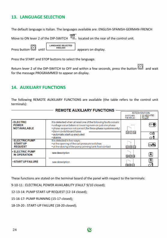
13. LANGUAGE SELECTION
The default language is Italian. The languages available are: ENGLISH-SPANISH-GERMAN-FRENCH
Move to ON lever 2 of the DIP-SWITCH located on the rear of the control unit.
Press button until appears on display.
Press the START and STOP buttons to select the language.
Return lever 2 of the DIP-SWITCH to OFF and within a few seconds, press the button and wait for the message PROGRAMMED to appear on display.
14. AUXILIARY FUNCTIONS
The following REMOTE AUXILIARY FUNCTIONS are available (the table refers to the control unit terminals):
These functions are stated on the terminal board of the panel with respect to the terminals:
9-10-11 : ELECTRICAL POWER AVAILABILITY (FAULT 9/10 closed);
12-13-14: PUMP START-UP REQUEST (12-14 closed);
15-16-17: PUMP RUNNING (15-17 closed);
18-19-20 : START-UP FAILURE (18-20 closed);
LANGUAGE SELECTED ENGLISH
25
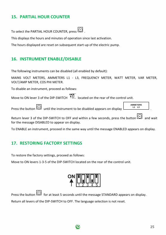
15. PARTIAL HOUR COUNTER
To select the PARTIAL HOUR COUNTER, press .
This displays the hours and minutes of operation since last activation.
The hours displayed are reset on subsequent start-up of the electric pump.
16. INSTRUMENT ENABLE/DISABLE
The following instruments can be disabled (all enabled by default):
MAINS VOLT METERS, AMMETERS L1 - L3, FREQUENCY METER, WATT METER, VAR METER, VOLT/AMP METER, COS PHI METER.
To disable an instrument, proceed as follows:
Move to ON lever 3 of the DIP-SWITCH located on the rear of the control unit.
Press the button until the instrument to be disabled appears on display .
Return lever 3 of the DIP-SWITCH to OFF and within a few seconds, press the button and wait for the message DISABLED to appear on display.
To ENABLE an instrument, proceed in the same way until the message ENABLED appears on display.
17. RESTORING FACTORY SETTINGS
To restore the factory settings, proceed as follows:
Move to ON levers 1-3-5 of the DIP-SWITCH located on the rear of the control unit.
Press the button for at least 5 seconds until the message STANDARD appears on display.
Return all levers of the DIP-SWITCH to OFF. The language selection is not reset.
AMMETERS L1 L3
26
18. GENERAL CONDITIONS
18.1 Warranty
The product warranty is subject to the general terms of sale of the company Elentek S.r.l.
Acknowledgement of the warranty depends on the strict and proven observance of the operating instructions in this booklet and application of the correct mechanical, hydraulic and electro-technical practices.
All products are covered by a warranty valid for 12 months, which covers all construction defects of our products and includes the replacement/repairs of defective parts.
The warranty will not be deemed valid in the event of:
- tampering with the panel (modifications without prior authorisation); - faults due to lack of or inadequate protection and/or connection errors; - faults caused by exceeding data plate specifications; - normal wear and tear of the panel; - failure by installation personnel to observe the specified operating procedures; - accidental causes, natural disasters of any kind, such as fires, flooding or lightning;
The defective material must be delivered carriage paid to Elentek S.r.l., who reserves the right to final judgement of the cause of the said defects.
The Warranty applies exclusively to restoring the original product characteristics and does not cover material damage or physical injury.
18.2 Maintenance
REACTO-EN does not require routine maintenance provided that it is used within the operating limits and in observance of the instructions in this manual.
Special maintenance or repairs must be performed exclusively by authorised service centres.
In the event of repairs, only original spare parts must be used.
The manufacturer declines all liability for material damage or injury to persons or animals caused by maintenance interventions performed by unauthorised personnel or using non-original materials.
18.3 Disposal
In the event of disassembly and scrapping, strictly observe local legislation regarding pollution.
Waste disposal according to material categories is recommended.
27
19. DECLARATION OF CONFORMITY
ELENTEK Srl with registered offices in via A. Meucci, 5/11 - 35028 Piove di Sacco (PD) ITALIA, declares under its sole responsibility that the machine:
REACTO-EN series
installed and used in the ways and for the purposes described in the operation and instruction manual complies with the provisions of the EU directives and relative amendments:
European Directive 2014/35 UE
Electromagnetic Compatibility 2014/30 UE and subsequent amendments, in compliance with
the following technical standards:
EN 61439-1
EN 55014-1
EN 61000-3-2
EN 61000-3-3
Piove di Sacco, 01.02.2016 LEGAL REPRESENTATIVE
Michele Borgato

28
NOTE

29
NOTE

30
NOTE


ELENTEK SRL SOCIETÀ UNIPERSONALE
Via A. Meucci 5/11 - 35028 Piove di Sacco (PD) - ITALIA
Tel. +39 049 9730367 - Fax +39 049 9731063
www.elentek.com - [email protected]
P.IVA 04534630282
Cod. MQ EN 0004 UK
Rev. 01
Em. 01.2018


