51
HHSMP-71-26 REACTOR AYALYSIS PROGRAM (TCHREACT) F. Z. ffonea, Development Vivdion md T. R. Ghch, Sqatm VivAian DEVELOPMENT DIVISION MARCH 1971 Normal Process Development Endeavor No. 102
HHSMP-71-26
R E A C T O R A Y A L Y S I S P R O G R A M ( T C H R E A C T )
F. Z. ffonea, Development V i v d i o n m d
T. R. Ghch, S q a t m V i v A i a n
DEVELOPMENT DIVISION
MARCH 1971
Normal Process Development Endeavor No. 102

NOTICE
ment. Neitb
es any legal liability e accuracy, co

MHFM? - 7 3. - 26
CHEMICAL R~ACTOR ANALYSIS PROGRAM (TCHREACT)
The purpose of this a c t i v i t y i s T o develop a computer program for d e t e r m i n h g safe opPraxing parameters fo r exothermic chex,ical reacticfis.
DISCLAIMER
This report was prepared as an account of work sponsored by an agency of the United States Government. Neither the United States Government nor any agency thereof, nor any of their employees, makes any warranty, express or implied, or assumes any legal liability or responsi- bility for the accuracy, completeness, or usefulness of any information, apparatus, product, or process disclosed, or represents that its use would not infringe privately owned rights. Refer- ence herein to any specific commercial product, process, or service by trade name, trademark, manufacturer, or otherwise does not necessarily constitute or imply its endorsement, recom- mendation, or favoring by the United States Government or any agency thereof. The views and opinions of authors expressed herein do not necessarily state or reflect those of the United States Government or any agency thereof.
March 1 9 7 1 Endeavor No. 102
A C C ~ e NO. 22-2-44-04-302

CONTENTS
SUMMARY .................................................................... Page
i v
1.0 PROGRAM DESCRIPTION ................................................... 1
2. 0 METHOD OF SOLUTION .................................................... 3
2.1 General .......................................................... 2.2 Batch Mass. Volume and Thermodynamic Properties .................. 2.3 Heat Transfer Coefficients .......................................
3 3 5
2.3.1 Batch L i q u i d Heat Transfer Coefficient .................... 5 2.3.2 Wall Thermal Conductivity ................................. 6 2,3.3 Coolant Heat Transfer Coefficient ......................... 6 2.3.4 Overall Heat Transfer Coefficient ......................... ?
2.4 Reaction Rate Equations .......................................... 2.5 Batch Temperature ................................................ 9
10
3.0 INPUT INSTRUCTIONS ..................................................... 13
3.1 Input Data ........................................................ 13 i
3.1,l Problem Identification .................................... 13 3.1.2 Problem Parameters ........................................ 13 3.1.3 Feed Data ................................................. 15 3.1.4 Reactant Data ............................................. 16 3.1.5 Coolant Data .............................................. 16 3.1.6 Vessel and Agitator Data .................................. 17 3.1,7 Miscellaneous Data ........................................ 18
3.2 Program O u t p u t ................................................... 18
4.0 PROGRAM INFORMATION ................................................... 4.1 Flow Chart ....................................................... 4.2 Variable Name Glossary ........................................... 4. 3 Program Source L i s t i n g ...........................................
19
20 27 30

Page
5.0 EXAMPLE PROBLEM ....................................................... 36
5.1 Problem Description .............................................. 36 5.2 Program Input Data ............................................... 38
5.2.1 Problem Identification .................................... 38
5.2.3 Feed Data ................................................. 38 5.2.4 Reactant Data ............................................. 38 5.2.5 Coolant Data .............................................. 38
5.2.7 Miscellaneous Data ........................................ 39
5.2.2 Problem Parameters ........................ i. .............. 38
5.2.6 Vessel and Agitator Data .................................. 39
5.3 Program O u t p u t ................................................... 39
6.0 CONCLUSIONS ........................................................... 43
7.0 REFERENCES ............................................................ 44
CHEMICAL REACTOR ANALYSIS PROGRAM (TCHREACT 1
SUMMARY
The synthesis o f many chemical compounds produces potent a l l y dangerous exo- thermic reactions. techniques fo r the calculation of the batch temperature as a function of time. ( a ) total batch and mass volume, ( b ) coolant and batch average thermodynamic properties, ( c ) heat transfer coeff ic ients for the batch, wall , coolant, and the overall "U" value, and ( d ) reaction ra tes f o r zero t h r o u g h 3rd order reactions. The program is to be used for determining operating c r i t e r i a (coolant flow r a t e , reactant feed r a t e , ag i ta tor speed, e tc . ) for maintaining batch temperatures a t a safe level fo r processes w i t h h i g h exothermic heats of reaction or mixing.
The FORTRAN IV program described her i n employs analytical n a chemical reactor
The program includes provisions for calculating
-i v-

1.0 PROGRAM DESCRIPTION
A chemical reactor i s basically a vessel for mix ing and retaining a mixture d u r i n g a chemical reaction. agi ta tor , and (b) an insulated jacket. The agi ta tor is used t o assure uniform reaction and t o prevent concentrated local violent reactions, and the jacket i s used to control the temperature of the reaction. The majority o f reactor vessels are of the vertical model as shown i n F i g . 1. For most modes of operation an exothermic reaction is carried out i n batches w i t h one or more reactants i n solution poured i n t o the reactor before another more potent reactant or ca ta lys t is added t o the batch in the reactor.
Most of these vessels include ( a ) baffles and an
The mixing and chemical reactions of materials w h i c h generate an exothermic heat of reaction can create conditions of hazardous , h i g h temperature opera- t i o n known as thermal runaway. reacting materials may, fo r example, vaporize and g i v e off toxic fumes or explosive vapors which in turn may ignite. Because t h i s dangerous potential exis ts , adequate controls must be provided and analyses must be made t o assure that temperature r i s e is held to a safe level. In addition, the control of the temperature r i s e may be desirable to optimize the yield a t nearly isothermal conditions.
If the heat generated is sufficient, the
The conditions f o r thermal runaway to ex i s t can be controlled by means o f any one of several parameters such as the reactant feed r a t e , the agi ta tor shape and speed, the concentration o f reactants, and the coolant flow ra t e and temperature. parameters may be entered as input d a t a for the calcu'iation o f the batch temperature as a function of time. e te rs will lead to the desired control o f the batch temperature and will effectively i n d cate safe operating conditions for the actual pilot-plant synthesis.
A computer program has been designed so tha t a l l o f these
A proper selection of operating param-
-1-

r .
& Variable I Drive Ai r
i b
TOPHEAD \
Jacket - & REACTOR VESSEL
F l u i d
Vessel Wall Baffle
Agitator - Shaft Cool i ng Jacket -r
Jac e I F1 u i d
3
F i g . 1. Typical Chemical Reactor
-2 -

2.0 METHOD OF SOLUTION
2.1 GENERAL
A computer program has been w r i t t e n i n FORTRAN I V f o r implementation on t h e IBM 360/40. Conversion t o o the r smal le r computers and program languages i s poss ib le s ince s torage requirements a re minimal.
The basic program f l o w c h a r t g iven i n F ig . 2 i nd i ca tes the major c a l c u l a t i o n s and loops. The program begins w i t h the summation o f t he batch mass and volume and the c a l c u l a t i o n o f the average thermodynamic p roper t i es f o r t h e batch (2.2). The heat t r a n s f e r c o e f f i c i e n t s a r e then ca l cu la ted (2.3) i f no t g iven as i n p u t data. zero o r h ighe r o r d e r reac t i ons (2.4). The heat t r a n s f e r c o e f f i c i e n t s -and r e a c t i o n r a t e (2.5) a re used i n computing the batch temperature. the t ime i s stepped up and c a l c u l a t i o n s (2.3) through (2.5) are repeated f o r the next t ime i n t e r v a l . amount o f temperature r i s e i n a t ime i n t e r v a l and f o r s e t t i n g d i f f e r e n t c a l c u l a t i o n and p r i n t o u t t ime i n t e r v a l s f o r each s p e c i f i e d s e t o f t ime l i m i t s .
Fo l low ing t h i s , t h e program ca lcu la tes r e a c t i o n ra tes , i f present, f o r
And, f i n a l l y ,
Added p rov i s ions are inc luded f o r c o n t r o l l i n g t h e
2.2 CALCULATION OF BATCH MASS, VOLUME AND THERMODYNAMIC PROPERTIES
The masses and thermodynamic p roper t i es f o r up t o f i v e cons t i t uen ts i n the batch and two c o n s t i t u e n t s i n the feed can be inc luded i n the i n p u t data (discussed i n Sec t ion 3.0) . The i n i t i a l t o t a l mass i s ca l cu la ted by summing t h e number o f s p e c i f i e d batch c o n s t i t u e n t masses. i s a l so c a l c u l a t e d by summing the mass o f each c o n s t i t u e n t d i v ided by i t s dens i ty .
The i n i t i a l batch volume
Thermodynamic p r o p e r t i e s f o r t h e i n i t i a l batch, such as thermal conduc t i v i t y , v i s c o s i t y , and s p e c i f i c heat, a re determined by use of a mass-averaging tech- nique f o r t h e i n i t i a l batch cons t i t uen ts (Equation 1).
N c (Mass x Proper ty )
To ta l I n i t i a l Mass Average Proper ty = 1 , N = Number o f Reactants
The values obta ined a re no t accurate f o r some s o l u t i o n s and reac t ions ; however, t h i s method o f averaging provides estimates which q u i t e o f t e n w i l l be c lose t o t h e ac tua l values. The s p e c i f i c heat values f o r each c o n s t i t u e n t i nc lude two constants t o p rov ide a l i n e a r v a r i a t i o n w i t h temperature. The i n i t i a l batch dens i t y i s c a l c u l a t e d separa te ly by d i v i d i n g t h e i n i t - i a l batch t o t a l mass by the t o t a l volume ca lcu la ted p rev ious l y . As the t ime -incrkases and t h e amount o f feed mass i n the batch increases, the batch mass, volume and thermodynamic p r o p e r t i e s a re r e c a l c u l a t e d by adding t h e mass-averaged values o f t h e added feed c o n s t i t u e n t s .
-3-
..

ST ART
Input Data W r i t e : i n p u t
Batch Mass, Volume Average Thermodynamic Write: Mass, Volume Properties: p , Cp, 1-1, K
2.3 Yes
Coolant Film Coefficient Batch Film Coefficient
0 Overall Coefficient 1 1
A 1. Reaction Rate I
1
2.5
10 Batch Temperature, T’ 1
~
ri te: t , hg, hc, U , T
F i g . 2. Chemical Reactor Analys s (TCHREACT) Computer Flow Diagram
-4- \

2.3 CALCULATION OF HEAT TRANSFER COEFFICIENTS
The program offers an option for calculation of the heat transfer coefficient for the batch, wall , and coolant and the resul t i n g overall coeff ic ient , U . a value of U is unknown, an i n p u t value of U = 0.0 into the program will i n i t i - a t e the calculation routine. have been described i n a previous report [2] .
If
The equations f o r the batch arid coolant coefficients
2.3.1 Calculation of Batch L i q u i d Heat Transfer Coefficient
The equation for the heat transfer coefficient, h , for agitated vessels w i t h an internal cooling coil or external cooling j a c k h i s :
where a = agitator constant
C p = specific heat (batch)
Da = agitator diameter
Dr = vessel internal diameter
k = thermal conductivity (batch)
N = agitator velocity
p = density (batch)
v = batch viscosity
pw = batch viscosity a t the wall
The value of "a" has been determined [3] to be
a = 0.87 paddle agitator
a = 1.50 turbine agitator
a = 0.83 propeller agitator
-5-

for internal cooling c o i l s , and
a = 0.36 paddle agi ta tor
a = 0.62 turbine ag i ta tor
a = 0.54 propeller agi ta tor
a = 0.46 anchor ag i ta tor
for external cooling jackets.
The Sieder-Tate viscosity correction, (v /uw)O-14, i n Equation - 2 is not included i n the program since the viscosity variation w i t h temperature a t the wall i s not included. This correction factor is negligible i n relation to the over- a1 1 t ransfer coeff ic ient , U, for many batches, especial ly for ma l 1 temperature changes.
2.3.2 Wall Thermal Conductivi ty
The wall thermal conductivities and thicknesses f o r the most popular chemical reactors a re listed i n Table I . The data on wall thickness and some of the thermal conductivity data has been obtained from [3] and [4].
Tab1 e I Wall Thermal Conducti vity
Thickness Materi a1 ( i n )
Glass, Pyrex Tube
G 1 ass-Lined G1 ass Steel
Stainless Steel ( 100-Gall on Si ze)
Type 316
.09375
.06
.688
.25
2.3.3 Coolant Heat Transfer Coefficient
Conducti v i ty , k ( B t u - i n / s q f t - F -h r )
8.0
6.5 30.0
8.9
Total (k/X) ( B t u / F - h r )
85.3
89.5 523
356
For the coolant flow through the spiral tube heat exchanger or coolant jacket , the heat t ransfer coeff ic ient can be estimated from the following equations:
-6- \

"t " I K m 8 c u hc = 0.028 (z)' ( L ) a 1 ' + [ 1 + 3.54 - VW
4m for - > 2100 (turbulent flow) .rrl.lD
or
h C = 0.94 [( 5) (TI 1'3 (k)*'"
(3)
L for - 4m W D
2100 and E > 10 (laminar flow)
where-h, = coolant heat t ransfer coefficient
L = flow length
m = mass flow ra t e
D
D, = flow path turn diameter
C p , p, pw, k = coolant thermodynamic properties
= tube or hydraulic diameter
Equation 3 i s based on t he Reynold's analogy for fully-developed, turbulent tube flow w i t h the factor ( .028) determined empirically. ( p / p w ) * 1 4 is the Sieder-Tate correction for wall viscosity and the ra t io
The r a t io of
1 + 3.54 - i s a correction for the spiral flow effect as introduced [ D t " 1 by Jacob 151. Graetz [6] w i t h the constant detemined empirically and w i t h the Sieder-Tate
In the program, the Sieder-Tate correction f o r the coolant flow has again, as for the batch, been assumed t o be equal t o 1.0. However, Marshall and Yazdani 173 have uti l ized a Dittus-Boelter type change i n the Prandtl number exponent of 0.3 for cooling and 0.4 f o r heating of the coolant. This change i n exponent can correct for wall effects and may be incorporated into a l a t e r version of the program.
Equation 4 for laminar flow was theoretically derived by
correction for viscosity. -
2.3.4 Calculation of Overall Heat Transfer Coefficient
The overall heat transfer coefficient is computed based on the ser ies heat transfer resistance concept as
(4)
1 1
u = (5)
Table I1 Summary - Overall Heat Transfer Coefficients 121
Heat Cool a n t Measured U - Coefficient
Area Speed Coolant Rate (Averaqe) Transfer Aai t a t o r F 1 ow LMTD (BtU/hr- F-sq Ft)
(sq F t ) (rpm) Reactant ( lb/hr) ( F ) Measured Estimated Literature - -- ~- -_-- ~-
2,6 (e ) None
Ethyl - 0 23 Alcohol
Hol 1 ow Water 3600 40 67 2 6 69.3
6 ” D. 188
200-Li t e r Tu be, Water
Hot Water Glass,
Water (Corning)
48 72 f 7 70.2 3590
Steam Water 9 1 72 k 7 69.8 66.3 (a)*
100-Sal lon , \13ried,
30.27 not Water S i g n i f i - rciater
G 1 ass-Lined S teel
(Pfaudl e r ) cant Steam
Water ___
(b) 4 1 62 t 6 57.3 50-60
( a ) 79.6 63 k 8 74.3 66.5
200-Gal 1 on , Glass-Lined
IC) None
Ethyl - 0 23 0.53 A1 coho Varied
39.35 rPm Water Water
Steel (Pfaudler) % 100
Steam Nater
9620 66.2 55 f 5 57.3 50-60 f b )
fa) 131 58 f 7 74.3 66.5
Water Turbi ne, Water
100- Gal lon ** Stainless 24.2 Operat-
S teel i ng Steam (Pfaudler) Water
** 88
(a) * ** 134 116
-_I_
( a ) 3 e Pfatldler Cornpan?, BAZLc;in ,523 [41 ( b ) ?mry, Chemical Engineers ?‘;7ndLc;2 [S I ** IJo experimental data (c ) [91
* Corrected t o neu wall t h i ckness
-8-
Typical values for U as measured and as calculated from equation 2 , 3, and 5 are shown in Table 11. The calculated values of U are i n good agreement w i t h the measured values for a l l cases (with a maximum deviation of 12% from the quoted 1 i terature values) .
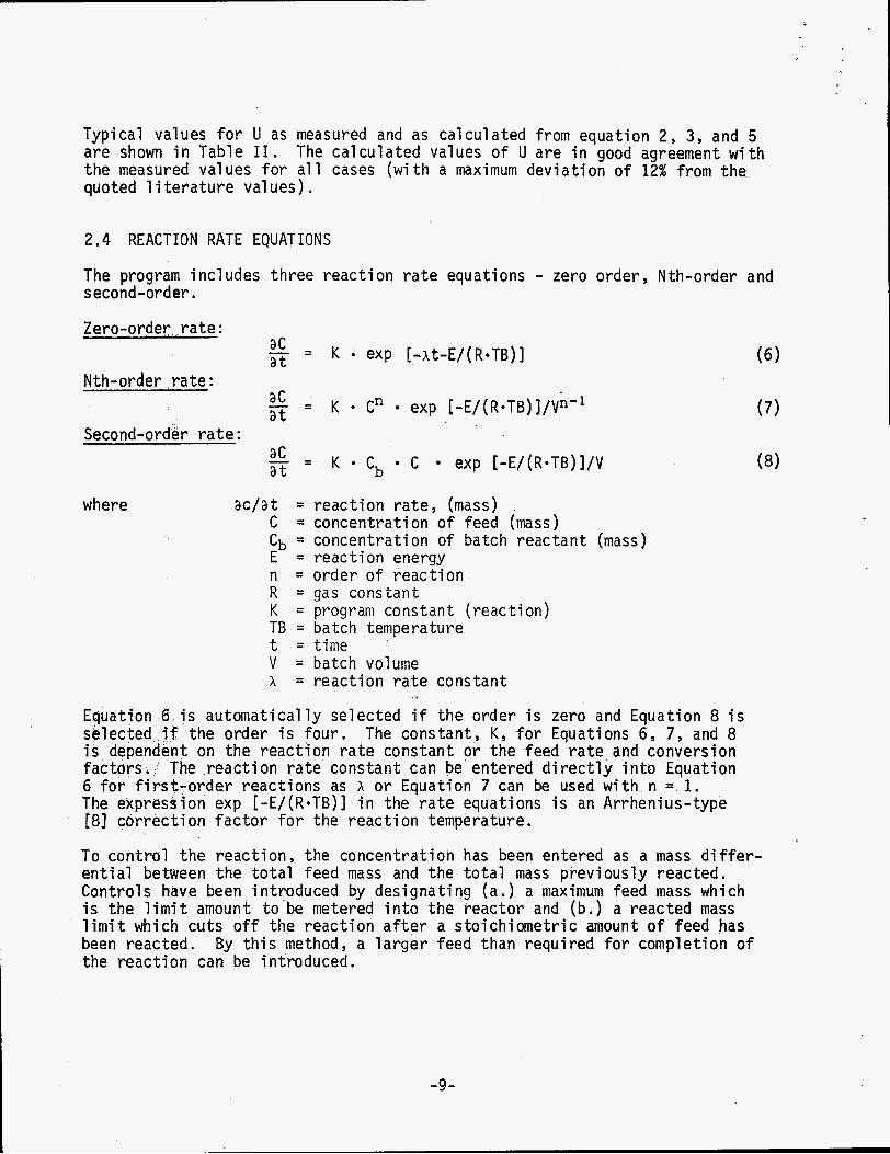
2.4 REACTION RATE EQUATIONS
The program includes three reaction ra te equations - zero order, Nth-order and second-order . Zero-order ra te :
a C - - a t - K * exp [ - A t - E / ( R * T B ) ] Nth-order . r a t e :
Second-order ra te : (7 ) - . - a' - K a C" exp [-E/(R*TB)]/V*-'
a t
a C a t - K Cb C exp [ - E / ( R * T B ) ] / V (8) - -
where ac/at = reaction r a t e , (mass) C = concentration of feed (mass) Cb = concentration of batch reactant (mass) E = reaction energy n = order of reaction R = gas constant K = program constant (reaction) TB = batch temperature t = time V = batch volume A = reaction ra te constant
Equation 6 is automatically selected i f the order i s zero and Equation 8 i s selected. i f the order i s four. The constant, K, for Equations 6 , 7 , and 8 i s dependent on the reaction ra te constant or the feed rate and conversion factors. The reaction rate constant can be entered directly into Equation 6 f o r f i r s t -order reactions as A o r Equation 7 can be used w i t h n = 1. The expression exp [ - E / ( R * T B ) ] in the ra te equations i s an Arrhenius-type [8] correction factor for the reaction temperature.
To control the reaction, the concentration has been entered as a mass differ- ential between the to t a l feed mass and the total mass previously reacted. Controls have been introduced by esignating ( a . ) a maximum feed mass which i s the l imit amount t o be metered into the reactor and ( b . ) a reacted mass l imit which cuts off the reaction a f t e r a stoichiometric amount of feed has been reacted. By this method, a arger feed t h a n required for completion of the reaction can be introduced.
-9 -

where
Most reac t i ons f o r explos ives svnthes is a re i n s o l u t i o n w i t h a b imolecular r e a c t i o n such as aA + bB ---+ CC + dD. and a va lue f o r K can usua l l y be estimated from data presented i n the l i t e r a - t u re . Moelwyn - Hughes 181 l i s t s a t h e o r e t i c a l va lue o f A = 3.5165 x 10¹³ cu. f t / l b - h r f o r many b imolecular reac t i ons where h = A exp I-E/(R TB) ] . For t y p i c a l values o f E = 22,000 cal/gm and TB = 600 R, t h e r e a c t i o n r a t e constant becomes A = 58.9 cu f t / ( l b -mo le*h r ) - -wh ich can be i n p u t t o the program wi th E = 0 as K = 58.9/MW (MW = molecular weight of batch reac tan t ) . E i t h e r Equation 7 w i t h order 2 o r Equation 8 can be used f o r b imo lecu la r reac t i ons . However, Equation 8 should be more accurate f o r most cases s i n c e the feed r e a c t a n t concentrat ion and the batch concent ra t ion d i f f e r apprec iab ly .
For these reac t i ons , n = 2,
Equation 7 i s use fu l when the feed r e a c t a n t i s very r e a c t i v e ; then the ba tch reac tan t concent ra t ion may n o t be c r i t i c a l . f o r t he f i r s t - o r d e r r e a c t i o n can be est imated as presented i n F ig . 3, p r o v i d i n g an approximate t i m g i s known f o r t h e completion o f t he r e a c t i o n o r f o r reach ing the maximum batch temperature. w i l l be c lose t o the same t ime as t h a t requ i red f o r complet ion o f the r e a c t i o n i f the heat o f t he r e a c t i o n i s d i r e c t l y r e l a t e d t o the mass reacted.
The r e a c t i o n r a t e constant, A ,
The t ime f o r reaching the peak batch temperature
I f the feed r e a c t a n t i s extremely r e a c t i v e , t h e feed r a t e may c o n t r o l t h e r e a c t i o n r a t e . For t h i s cond i t i on , a zero-order r e a c t i o n may be used (Equation 6) w i t h ,
K = feed r a t e
2.5 BATCH TEMPERATURE
(9)
The energy balance f o r t he batch r e a c t o r should i nc lude a t l e a s t three equations: (1) heat t r a n s f e r from o r t o the coo lan t from the batch, ( 2 ) heat t r a n s f e r and energy storage i n t h e vessel wa l l s , and ( 3 ) energy t r a n s f e r , r e a c t i o n and s torage i n the batch. a t Pantex, t h e h igh coo lan t f l o w ra tes r e s u l t i n h igh f i l m c o e f f i c i e n t s (Q 1300 Btu/hr . sq. ft. - F) and a small temperature r i s e (QJ 5 F) i n t h e coolant . Thus, t h e coo lan t temperature and c o i l o r vessel w a l l i s h e l d e s s e n t i a l l y constant dur ing the reac t i on . average temperature f o r the coolant , t h e th ree energy equations can be reduced t o one equat ion f o r t he batch:
However, f o r t h e chemical reac tors used
With use o f an estimated constant
(Cp:)B = batch s p e c i f i c heat mass (Cpm)f = s p e c i f i c heat r a t e ( feed)
= temperature r a t e (batch) a t
-10-

30
20
10
0 2
o r , i n t e g r a t i n g , -At C = Coe
-1 = rate c o n s t a n t , hr
10 20 30 60 3 4 5
T i m e t o 99% of Peak (minutes)
F i g . 3 . First-Order React ion Rate Constant Estimate Curve
-11-
~~ ~
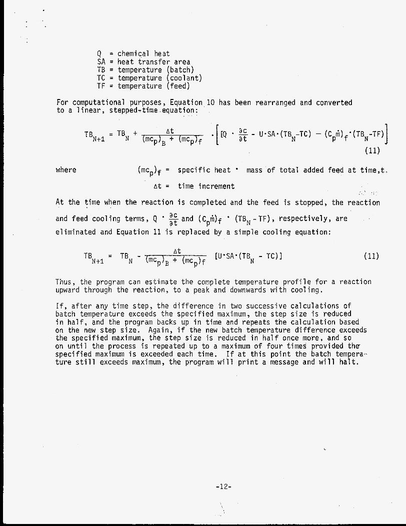
Q = chemical heat SA = heat transfer area TB = temperature (ba tch ) TC = temperature (coolant) T F = temperature (feed)
For computational purposes , Equation 10 has been rearranged and converted t o a 1 inear , stepped-time .equation:
where (mc,)f = specific heat mass o f total added feed a t t ime,t .
A t = time increment
A t the time when the reaction i s completed and the feed is stopped, the reaction
and feed cooling terms , Q eliminated and Equation 11 i s replaced by a simple cooling equation:
. ac at and (Cpiii)f (TB, - TF) , respectively, are
Thus, the program can estimate the complete temperature profile for a reaction upward t h r o u g h the reaction, t o a peak and downwards with cooling.
I f , a f t e r any time s tep, the difference i n two successive calculations of batch temperature exceeds the specified maximum, the step s ize i s reduced i n h a l f , and the program backs up i n time and repeats the calculation based on the new step s ize . the specified maximum, the step s ize i s reduced i n half once more, and so on u n t i l the process i s repeated u p t o a maximum of four fimes provided t h e specified maximum -is exceeded each time. ture s t i l l exceeds maximum, the program will print a message and will hal t .
A g a i n , i f the new batch temperature difference exceeds
I f a t th is p o i n t the batch tempera-
-12-
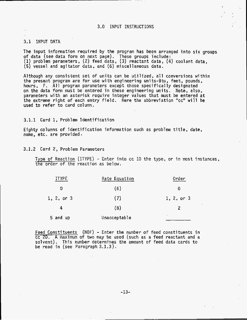
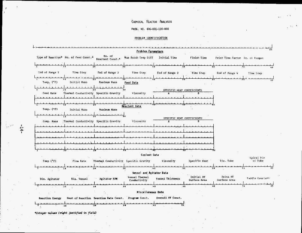
3.0 INPUT INSTRUCTIONS
3.1 INPUT DATA
The input information required by the program has been arranged into s ix groups of data (see d a t a form on next page). (1) problem parameters, (2) feed data, (3 ) reactant data, (4) coolant d a t a , (5) vessel and agi ta tor data, and (6) miscellaneous data.
These groups include:
Although any consistent s e t of units can be u t i l i zed , a l l conversions w i t h i n the preseilt program are fo r use w i t h engineering units-Btu, f ee t , pounds, hours, F. All program parameters except those specif ical ly designated on the data form must be entered in these engineering units . Note, also, parameters w i t h an aster isk require integer values that must be entered a t the extreme r i g h t of each entry f i e ld . Here the abbreviation "cc" will be used t o re fer t o card column.
3.1.1 Card 1, Problem Identificatton
Eighty columns of ident i f icat ion information such as problem t i t l e , date, name, e tc . are provided
3.1.2 Card 2 , Problem Parameters
Type of Reaction (ITYPE) - Enter into cc 10 the type, or in most instances, the order of the reaction as below.
ITYPE Rate Equation
0 (6 1 Order
0
1, 2 , o r 3 (7) 1, 2, o r 3
4 ( 8 ) 2
5 and up Unacceptable
Feed Constituents cc 20. solvent). be read i n (see Paragraph 3.1.3 ) .
(NOF) - Enter the number of feed constituents i n A maximum o f two may be used (such as a feed reactant and a
This number determines the amount of feed d a t a cards t o
-13-
I
P I
CHEMICAL kACTOR ANALYSIS
PROG. NO. 406-001-130-000
PROBLEM IDENTIFICATION
L . . . . . . . . . . . . . . . . . . . . . . . . . . . . . . . . . . . . . . . . . . . . . . . . . . . . . . . . . . . . . . . . . . . . . . . . . . . . . . . 1 8 0 Problem Parameters
Type of Reaction* No. of Feed Const.* Reactant Const.* H ~ x Batch Temp Diff In i t i a l Time F i n i s h Time P r i n t Time Fac to r 110. o t Ranges No. of
. . . . . . . . . . . . . . . . . . L I . . I . , A 4-l 40 5 0 6 0 7 0 n o 2 0 S O
~ , . ' . . . . . . !........'I l . . . . . . . . . I ! . . . . . . . . . I 1 0
End o f Range 1 Time S t e p End of Range 2 Time S t e p End of Range 3 Time S t e p End o f Range 4 T i m e S t e p 1 . . . . . . . . . l . . . . . . . . . I . . . . . . . . . l . . , . . . . . . I . . , . . . . . . I . , . . . . . . . I . . . . . . . . ,
8 0 1 0 2 0 3 0 40
Temp. (OF) I n i t i a l Mass Haximun Mass Feed Data ~ 1 1 1 1 1 1 1 1 1 1 1 1 1 1 1 1 1 1 l 1 l 1 1 1 1 1 1 1 1 1
I 1 0 2 0 3 0 SPECIFIC HEAT COEFFICIENTS Feed Rate Thermal Conduct ivi tv S p e c i f i c Grav i ty Vi scos i t v A B
. . . . . . . . 1 . . . . . . . . . . . . . . . . I . . . . . . . . * J , . . . . . . . . . . . . . . . 1 0 &$ctant Data
Temp. (OF) I n i t i a l Mass Maximm Mass i . . . . , . . . . l . . , . , . . . , I . . . . . . . . . I 2 0 3 0
1 0 SPECIFIC HEAT COEFFICIENTS
Comp. Mass Thermal Conduct ivi ty S p e c i f i c Grav i ty V i s c o s i t y A B
l . n . . . . . a . I . 10 . . . . . . . . E . . . . . . . . . . . . . . . . . . . . . . . . . . . . . . . . . . . . . . . . . . . . . 0
Coolant Data S p i r a l Did
T m p (OF) Flow Rate Thermal Conduct ivi ty S p e c i f i c Grav i ty V i s c o s i t y S p e c i f i c Heat D i d . Tube of Tube
r . . . . . . . . . l . . . . . . . . . I . . . . . . . . . I . . . . . . . . . I . . . . . . . . . I . . . . . . . . . I . . . . . . . . . I . . . . . . . . # I 1 0 2 0 30 40 5 0 6 0 7 0 B O
Vessel and Agitator Data
Paddle Constant I n i t i a l HT Delta HT Dia. Agitator Dia. Vessel Agitator RPH v ~ ~ ~ ~ ~ ~ ~ ~ ~ l Vessel Thickness Surface Area Sur face Area
I . . . . . . . . . I . . . . . . . . . I . . . . . . . . . I . . . . . . . . . 1 . . . - . . . . . I * . . . ' . ' ~ . I . ' . . . . " ' ~ " . ' " ' ' ~ 1 2 0 3 0 b 0 5 0 6 0 7 0 8 0
l o . Miscellaneous Data
Reaction Energy Heat of React ion Reaction Rate Const . Prograa Const. O v e r a l l HT Const.
1 . . . . . . . . . l . . . . . . . . . I . . . . . . . . . l . . . . . . . . . l . . . . . . . . . J * * D 5 0 I I D 2 0
*Integorp opalwe (r ight justif ied in fioW

Reactant Constituents i n cc 30. a second-order reaction using Equa t ion 8 , the reactant i n the batch must be entered as the f i r s t batch constituent in the reactant data cards (see Paragraph 3.1.4).
( N O R ) - Enter the number of reactant constituents A maximum of f ive batch constituents may be specified. For
Maximum Batch Temperature Difference maximum allowable temperature increase for each time interval . be specified i n cc 31 t o 40. will be halved and i terat ion repeated up t o a maximum of four times.
(TMAX) - T h i s entry sets the
If the value is exceeded, the time interval I t must
In i t ia l Time the reaction i n hours (usually 0 . 0 ) .
(IT) - Enter into cc 41-50 the in i t i a l or s t a r t time of
F i n i s h Time the r e a c t c n i n hours.
(FINTIM) - Enter into cc 51-60 the f inish or end time fo r
Print Time Factor (RATIO) - Select the ed i t or printout time desired as a multiple of the calculation time step ( l . , lo., e t c . ) . i n cc 61-70.
Enter this value
Number of Ranges fo r the time step. T h i s allows the selection of up to four time ranges d u r i n g the reaction so tha t the calculation time step can be smaller d u r i n g c r i t i ca l periods of the reaction.
( N ) - Enter into cc 80 the number of desired values
Time Step and Range Card - Beginning sequentially, enter the end of the f i r s t time i n hours and the corresponding time step i n minutes for t ha t range inclusive into cc 1-10 and cc 11-20, respectively. Proceed simi- l a r ly w i t h the second s e t of values into cc 21-30 and cc 31-40, and continue on u n t i l the number N has been sa t i s f ied .
3.1.3 Card 3, Feed Data
Temperature ( T F ) - Enter i n t o cc 1-10 the temperature ( F ) of the feed constituents prior t o feed. T h i s value is constant for a run.
In i t i a l Mass (MFT) - Enter into cc 11-20 the in i t i a l mass i n pounds of feed for dumped or prior reacted feed (usually s e t as 0 . 0 ) .
Cards 3A-3B
Feed Rate - F i l l out as many cards as specified by NOF (see Paragraph -Enter the ra te of feed of the one or two feed constituents (pounds/hour) into cc 1-10.
-15-

Thermal Conductivity, Specific Gravity, Viscosity, Specific Heat ( A & B ) - fhese thermodynamic properties for a feed constituent must be specified i n cc 11-20, cc 21-30, cc 31-40, cc 41-50, and cc 51-60 i n the order as l i s t ed above. All properties are i n B t u , hours, pounds, f e e t , .F except specif ic gravity (no units). The "A" value for specific heat is a con- stant; the "B" value may be used for l inear variations i n specif ic heat w i t h temperature.
3.1.4 Card 4, Reactant Data
Temperature reactant constituents, (batch) prior t o the reaction.
(TR) - Enter into cc 1-10 the temperature ( F ) of the
In i t i a l Mass fo r the ag i ta tor and vessel walls (Dounds).
(MR) - Enter into cc 11-20 the inclusion of added mass
Maximum Mass (MRMAX) - (pounds) T h i s mass i s the total mass of the feed which must react to achieve complete reaction w i t h the batch reactant. T h i s mass includes the stoichiometric mass amount of feed reactant plus the proportional amount of the other feed constituent ( i f any) i n the total feed. Enter this value i n cc 21-30.
Cards 4A-4E
Corn onent Mass - Fi l l o u t as many cards as specified by NOR (see paragraph -- the amount o f mass i n pounds for a component i n the batch in cc 1-10. component masses d u r i n g the reaction a1 though the mass and heat capacity is continuously corrected fo r added feed mass. be the f i r s t component.
No provision has been made a t present for change-over of
The batch reactant must
Thermal Conductivity, Specific Gravity, Viscosity, and Specific Heat ( A & B) - These thermodynamic properties for a batch component must be specified i n cc 11-20, cc 21-30, cc 31-40, cc 41-50 and cc 51-60 i n the order as l i s ted above. All properties are i n engineering units except specif ic gravity which i s dimensionless. "A" order reactions using Equation 8 where ITYPE = 4 , the f i r s t component must be the batch reactant.
The specific heat includes provisions fo r a constant and a l inear coefficient of change "BII w i t h temperature. For second
3.1.5 Card 5, Coolant Data
Temperature T h i s temperature represents an estimated average f o r the cool ant ( i n l e t to ou t l e t p l u s time variation) for the total reaction r u n .
(TC) - Enter the temperature ( F ) of the coolant into cc 1-10.
Flow Rate 11-20 .- (RC) - Enter the flow ra t e of the coolant (pounds/hour) i n cc
-16-
Thermal Conductivity, Specific Gravity, Viscosity, Specific Heat - K t e r these thermodynamic properties of the cool a n t i n engineering units into cc 2 1 - 3 0 ; ’ 3 1 ~ 4 0 , ~ 4 1 ~ 5 0 ; - a n d - 5 1 ~ 6 0 - i n ’ the-okder as l i s t ed above. The specific heat i s just a single constant value. i f the overall heat transfer coefficient U is specified i n cc 41-50 of the miscellaneous data card (see paragraph 3.1.7).
Tube Diameter - Enter the flow diameter (inches) for a coolant passage i n t o cc 61-70. Use the hydraulic diameter i f tEe cross section of the tube is not c i rcular .
No properties are necessary
Spiral Diameter of Coil - Enter the spiral diameter (inches) for the coolant co i l s or for the jacket into cc 71-80. factor fo r curvature t o the heat transfer coeff ic ient) .
(Applies a correction
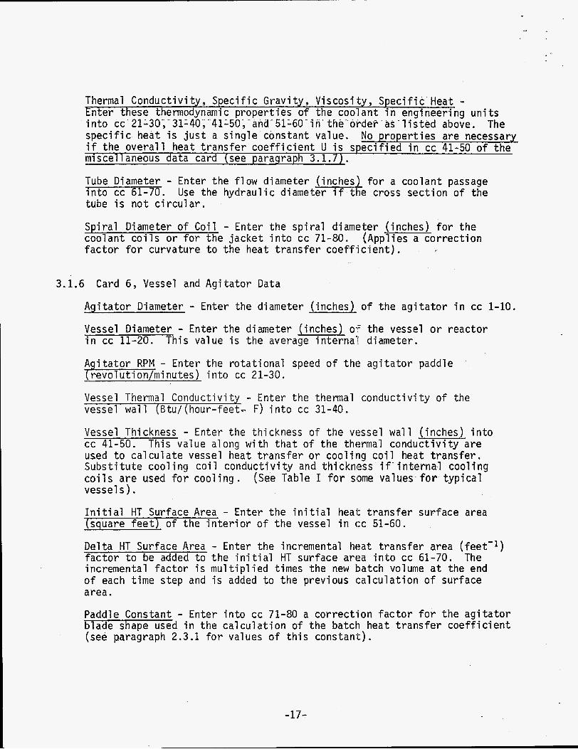
3.1.6 Card 6, Vessel and Agitator Data
Agitator Diameter - Enter the diameter (inches) of the agi ta tor i n cc 1-10.
Vessel Diameter - Enter the diameter (inches) o f the vessel o r reactor i n cc 11-20. This value is the average internal diameter.
A i t a t o r RPM - Enter the rotational speed of the agitator paddle P--- revoTution/minutes) into cc 21-30.
Vessel Thermal Conductivity - Enter the thermal conductivity o f the vessel wall (Btu/(hour-feet- F) into cc 31-40.
Vessel Thickness - Enter the thickness of the vessel wall (inches) i n t o cc 41-50. This value a long w i t h tha t o f the thermal conductivity are used t o calculate vessel heat t ransfer or cooling coil heat transfer. Substi tute cooling coil conductivity and thickness i f ’ internal cooling co i l s a re used for cooling. (See Table I for some values for typical vessel s ) . In i t i a l HT Surface Area - Enter the i n i t i a l heat transfer surface area (square f e e t ) of the inter ior of the vessel i n cc 51-60.
Delta HT Surface Area - Enter the incremental heat transfer area ( fee t - I ) factor to be added t o the in i t i a l HT surface area into cc 61-70. The incremental factor is multiplied times the new batch volume a t the end of each time step and i s added to the previous calculation of surface area.
Paddle Constant - Enter i n t o cc 71-80 a correction factor fo r the agi ta tor blade shape used i n the calculation of the batch heat transfer coefficient (see paragraph 2.3.1 for values of this constant).
-17-

3.1,7 Card 7 , Miscellaneous Data
Reaction Energy - Enter i n t o cc 1-10 the reaction energy fo r the Arrhenius- type temperature correction w i t h units of Btu/(pound-mole) . Heat of Reaction - Enter into cc 11-20 the heat of reaction i n terms of the feed reactant mass ( B t u / p o u n d ) . This concentration may include another constituent (usually a solvent).
Reactim Rate Constant - (hour- I ) - T h i s is a reaction r a t e constant ( A = LAM) as used i n the f i rs t -order reactions where
- - - A t a' - xcOe a t
Enter thl's value i n t o cc 21-30.
Program Constant - This constant i s used i n the reaction r a t e equations for conversions and reaction ra te constants. Enter this value i n t o cc 31-40.
Overall HT Coefficient - Enter i n t o cc 41-50 the value o f the overall heat t ransfer coefficient (Btu/(square fee t - F-hour) (Some representative value may be found i n Table 11.) or s e t t o O . , the heat t ransfer coefficient and overall coefficient are calculated by the program.
For an overall HT coeff ic ient l e f t blank
3.2 PROGRAM OUTPUT
The printed o u t p u t fo r the program includes ( a ) a summary form of a l l i n p u t variables and (b ) a presentation of the computed resul t s . outs of the i n p u t variables and resu l t s i s included i n Section 5.0. The summary of input variables i s arranged i n a format which is similar t o the Computer Data Input Form. All parameter values are labeled for ident i f icat ion.
The example pr in t -
The presentation of computed resu l t s begins w i t h the i n i t i a l values for the batch mass and volume. The resu l t s fo r each printout time are then presented i n order on a l i ne as follows: time, batch temperature, batch film coeff ic ient , coolant f i lm coeff ic ient , overall heat t ransfer coeff ic ient , to ta l feed mass, t o t a l reacted feed mass and heat t ransfer surface area. A t the end of the r u n , the r e l a t ive maximum and minimum temperatures and the i r associated times are indicated. I f the overall heat transfer coefficient is input (U # 0 ) , then the batch and coolant f i lm coefficients a re n o t computed and are recorded as "0" . Although the time and batch temperature are the main objective resu l t s f o r the program, the other p r i n t o u t information i s useful for checking the la t ransfer and reaction rates
-18-

4.0 PROGRAM INFORMATION
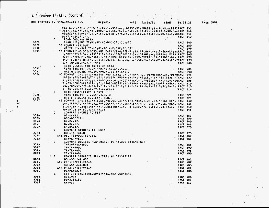
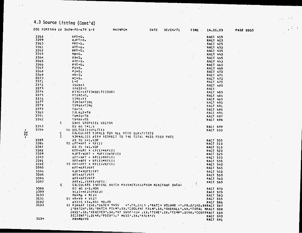
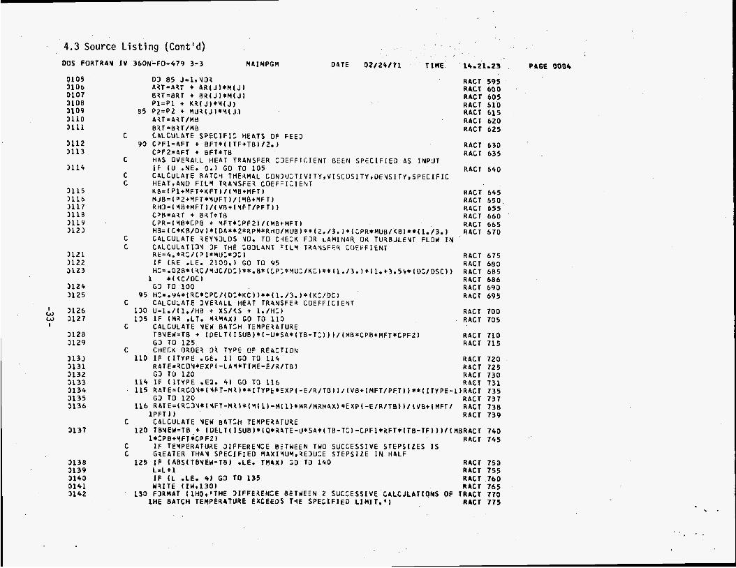
T h i s section includes the flow charts , variable name glossary, and program source listing for the TCHREACT program.
-19-

4.1 TCHREACT Flow C h a r t
START
d
TMAX, T I , FINTIM, RATIO, N , ( R E N D i ,
T C , R C , KC, P C MUC, C P C , DC,
t AD E WRITE
t EAD E WRITE i sc el lan-
input RCON, U
DC = DC/12 DSC = D S C / l 2 .
DA = D A / 1 2
DV = D V / 1 2
xs = X S J 1 2
DA, DV, RPM, KS, XS, S A ,
-20-
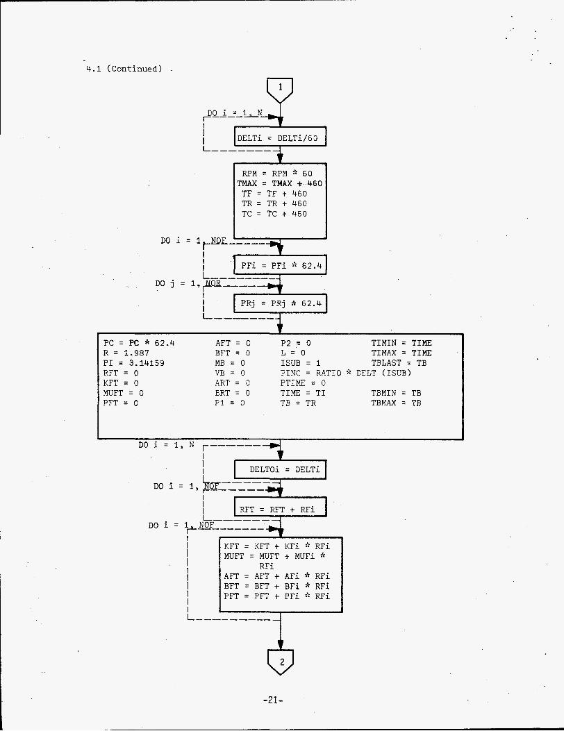
4 . 1 (Continued)
i
RPM = RPM :* 60 TMAX = TMAX t 460
TF = TF t 460 TR = TR t 460 TC = T C t 460
DO i = 1 t WE----- & i I I
PC = PC * 62 .4 AFT = 0 R = 1.987 BFT = 0 P I = 3 .14159 MB = 0 RFT = 0 VB = 0 KFT = 0 ART = 0 MUFT = 0 ERT = 0 PFT = 0 P 1 = 0
~~ ~ ~ ~~~~ ~~
P2 = 0 TIMIN = TIME L = O TIMAX = TIME ISUB = 1 TBLAST = TB PINC = RATIO f: DELT (ISUB) PTIME = 0 T I M E = T I TBMIN = TB TB = TR TBMAX = TB
DO i = I, )TOT-----
RFT = RFT + RFi DO i = 1 NOF 1 1 I------- +
I--------- ~~
KFT = KFT + KFi f: RFi MUFT = MUFT t MUFi * AFT = AFT + AFi 2: RFi BFT = BFT + BFi f: RFi PFT = PFT + P F i R F i
RFi
-21-

4.1 (Continued)
KFT = KFT/RFT MUFT = MUFT/RFT AFT = AFT/RFT BFT = BFT/RFT PFT = ~ . / ( P F T / R F T )
,D9 L z L N A R - r
V j = Mj/PRj MB = MB + M j VB = VB + V j
I $1 I I L -------- -
WRITE : MB, VB
-~~ ~ ~
PB = MB/VB 1
ART = ART + ARjeMj BRT = BRT + BRjcMj P1 = P1 + KRjsMj P 2 = P 2 + MURj$cMj
I ART = ART/MB I I BRT = BRT/MB 1
r 4
CPFl = AFT + BFT:t[(TF + TB)/2.] CPF2 = AFT + BFTzTB
I
-22-

4.1 ( C o n t i n u e d ) - P KB=(Pl+MFTf:KFT) /( MB+MFT) MUB=(P2+MFT:tMUFT)/(MB+HFT) RH@=(MB+MFT ) /( VB+ [ MFT /?FT] CPB=ART+BRT:tTB CPR=(MBKPB+MFTf:CPF2) /(MB+MFT) 1 / 3 HB=( CnKB/DV ) A ( DAf:f: 2:tRPMf:RH@/MUB ) 2: RE =4 . f;RC / ( P IaMU C f:DC )
2 / 3 CPRf:MUB KB
t HC=. 0 2 8 4 RC/MUC;tDC)3: .% (CPC*MUC/KC) 1/3 1
t I
1. 1. /HB+XS/KS+l , /HC u =
+ TB=TB+(DELT [ ISUB] a[ -U*SA*{TB-TC)) )
/ (MB*CPB+MmTnCPF2)
1 Yes -
RATE=RCQNne(-~AM*TIME-E/R/TB) 7
_RCQN~(MFTE/-H/R/TB) 11 . ATE-
( V B + w ) c v RATE= RCQ~*(YFT-MR)(M1-MIMR/MRMAX$
e( -E/R/TB)/(VB+MM'/PFT)
-23-
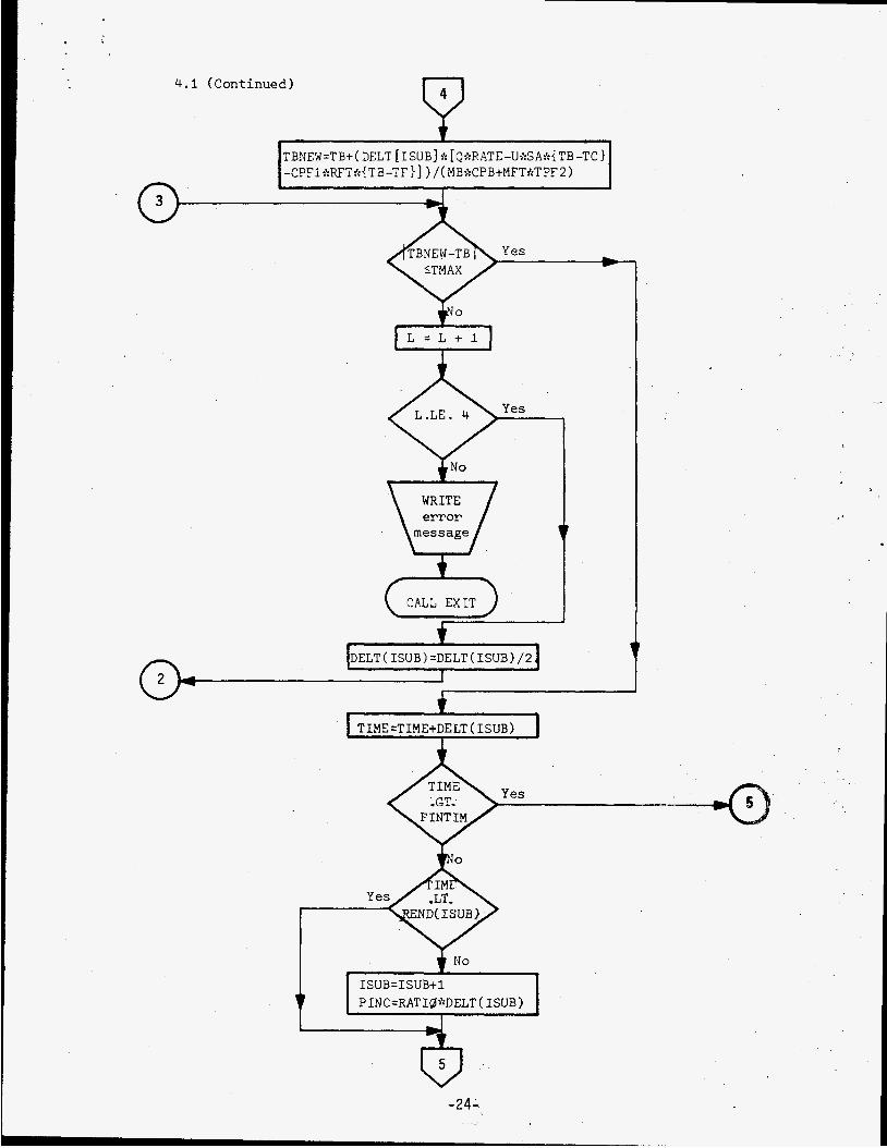
4.1 (Continued)
-24-
I
TBNEW=TB+( DELT [ISUB] ;'L [Q?:RATE-Ut':SA:':{TB-TC) -CPFif:RFTk{TB-TF}] ) /( MBf:C?B+MFTf:T?F2)
t
i CALL EXIT
ELT(ISUB)=DELT(ISUB)/2 I

4.1 (Continued) & PTIME=PTIME+?INC
L = O DELT( ISUB)=DELTQ( ISUB)
TBMINzTBMIN -460 T BM AX =T BM AX - 4 6 0
I A
0 CALL EXIT
MFT=MFT+RFTxDELT( ISUB) MR=MR+RATExDELT( ISUB) SA=SA+SAVx VB t MFT I (, =d
'I"C) MR=MFT
-25-
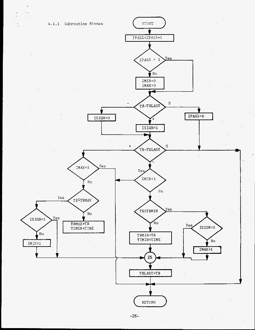
4.1.1 Subrout ine Xinmax
I P AS S =I P ASS +1
- 0 + IPASS=O ISIGN=O
i
I- T
8 I M X = l
TBMhX=TB
IMIN=l
TBMIN=TB TIMIN=TIME
I TBLAST =TB I I
0 RETURN
-26-

4.2 PROGRAM DATA NAME GLOSSARY
Data Name
AF(I)
J )
BF( 1)
B N J )
AFT
ART
BFT
B RT
C CPB CPC C P F l CPF2 CPR
DA DC
DELTO ( I ) DSC DV
E
FINTIM
HB HC
DELT ( I
ICARD ( I ) ITYPE
KB KC
KFT
KS
L LAM
W I )
KR( J 1
Definition or Cmment
Specific heat (constant) for each feed constituent Total feed specific heat (constant term) Specific heat (constant) for each reactant component Total specific heat of batch (constant term)
Specific heat (1 inear term) for each feed constituent Total feed specific heat ( l inear term) Specific heat ( l inear term) fo r Total specific heat o f batch (1
Paddl e constant Partial specific heat of batch Specific heat of coolant Average specific heat-of feed Partial specific heat of batch Specific heat of batch
Diameter of agi ta tor Diameter o f coolant coil Time step indicator Or ig ina l time step indicator Spiral diameter of coolant coil Diameter o f vessel
each reactant component near term)
rom feed
Reac t i on energy
F i n i s h time of reaction
Batch heat t ransfer coefficient Coolant heat t ransfer coefficient
Alphanumeric i n p u t information and problem description Order of reaction
Thermal conductivity of batch Thermal conductivity of coolant Thermal conductivity f o r each feed constituent Total feed thermal conductivity Thermal conductivity of each reactant component Vessel thermal conductivity
Counter heat t ransfer coefficient Reaction ra te constant
-27-

4.2 PROGRAM DATA NAME GLOSSARY (con t i nued)
Data Name Def i n i ti on or Comment
M B MFT MFMAX
MR MRMAX MUB MUC MUF( I) MU FT MUR(J)
M(J)
N NOF NOR
P 1 P2 PB PC PF(1) P FT PINC
PTIME P N J )
Q R RAT E RAT I O RC RCON RE REND(I) RFU) RFT RHO RPM
SA SAV
Tota l mass o f batch I n i t i a l mass o f feed Maximum a l lowab le mass. o f feed Mass o f each reac tan t component I n i t i a1 mass o f reac tan t Maximum a l lowab le amount o f feed t o r e a c t V i s c o s i t y o f batch V i s c o s i t y o f coo lan t V i s c o s i t y o f each feed c o n s t i t u e n t To ta l feed v i s c o s i t y V iscos i ty o f each r e a c t a n t component
Number o f d i f f e r e n t t ime s tep ranges Number o f feed cons t i t uen ts Number o f reac tan t components
To ta l thermal c o n d u c t i v i t y o f batch Tota l v i s c o s i t y o f batch Dens i ty o f r e a c t a n t Densi ty of coo lan t Densi ty o f each feed c o n s t i t u e n t To ta l feed d e n s i t y P r i n t t ime increment Dens i ty o f each r e a c t a n t component P r i n t t ime
Heat o f r e a c t i o n
Gas constant Chemical r e a c t i o n r a t e P r i n t t ime f a c t o r Mass f l ow r a t e o f coo lan t Program cons tan t Reynolds number End o f range f o r each d i f f e r e n t t ime s tep Mass f l o w r a t e f o r each feed c o n s t i t u e n t To ta l feed mass f l o w r a t e Dens i ty o f batch Speed o f a g i t a t o r paddle
Surface area o f i n s i d e vessel D e l t a sur face area f a c t o r
-28-

4 . 2 PROGRAM DATA NAME GLOSSARY (conti nued)
Data Name
TB TBF TBLAST TBMAX TBMIN TBNEW TC TF TI TIME TIMXN T IMAX TMAX TR
U
V B V(J j
~ ,. .i 3
Defi n i t i on or Comment
Ten pe r a t u r e of batch Temperature of batch for printout ( F ) Prevl ous batch temperature cal cul ated Relative maximum of time-temperature profile Relative minimum of time-temperature profile New temperature o f batch Temperature of coolant Temperature of feed StarLtime o f reaction Time o f reaction Time of re la t ive minimum batch temperature Time o f re lat ive maximum batch temperature Maximum allowable temperature increase of batch Temperature o f reactant
Overall heat transfer coefficient
T o t a l volume of b a t c h "*l , L t - , ~ z 0 ; each re2,:tant covponent
-29-

U1 r- U .3
X U F U 1T
n f
II c
- e
- c s -1-
7 a 6 c
U z . U c -a
N L M
U
J
DOS FORTRAY I V 3 6 0 N - F a - 4 7 9 3-3
3 3 2 9 3 3 2 9 3 3 3 3 3 3 3 1
3 3 3 2 3 3 3 3 3 3 3 4
3 3 3 5 3 3 3 6 3 3 3 7
3 3 3 8 3 3 3 9 3 3 4 3 3 3 4 1 3 3 4 2
3 3 4 3 3 3 4 4 3 3 4 5
3 3 4 6 3 0 4 7 3 3 4 8 3 3 4 9
3 0 5 0 3 3 5 1 3 3 5 2 3 3 5 3 3 3 5 4
3 3 5 5 3 3 5 6 3 3 5 7
c
M4 I NPGM D I T € 0 2 / 2 4 / 7 1 T I M E 14.21623
C
2AT C O E F o ' / l H * 'DE? f * r 4 X , ' H 4 S S ' r 6 X ~ ' M A S S ' r 5 X , ' M A S S ' ~ 3 X r ' C O N D U C T I V I R A ~ T 3 T ~ ' r Z 6 X ~ * A ' r 7 ~ ~ ' B ' / l H O ~ F 4 ~ O ~ 5 X ~ F 5 . l ~ 3 X ~ F 7 ~ 3 ~ 3 X ~ F 5 ~ l ~ 4 X r F 7 ~ 3 ~ 5 ~ ~ F b o R A C T 43r5X1F6.3,5X1F7o4r2X,F1.4/(1H 5, F7.4r2XsF7.4) 1 1 RACT
READ t I R , 5 0 ) T t r R ~ , r K C r P c , n u = ~ C P = , 3 C r D S C RACT 5 0 FDRMAT I B F 1 0 . 0 ) RAC r
H B f T E I I W . 5 5 ) T C i \ C r K t r P C r M ~ C , , P C , D 3 , ~ S 3 RACT 55 F 3 R M A T ~ l H O ~ 3 5 X ~ ' C 3 0 L A N T D 4 T 4 ' / 1 I O ~ ' T E M P ' , b X ~ ' F L D ~ ' ~ ~ X ~ ' T H E R M A L ' ~ 5 X R A C l
1, 'DENSITY ' 9 3 x 9 ' V I S C O S I T Y * , 3X 9 'SPE3 I F I t * 9 3 x 9 ' 0 1 AM' 9 4X ' S P I R A L 01 LYM'RACT 2/1H t 'DEC F ' r 3 X 9 ' \ A T E ' , 3 x 1 ' ;DY3UCTIVITY@ , ~ ~ X I ' H E A T * , g X * * T JBE' r 6 X t RACT 3 ' 3 F C ~ ~ L ' / ~ H ~ , F ~ . ~ ~ Z X I F ~ . O , ~ X , F ~ . ~ , ~ X , F ~ . ~ , ~ X , F ~ . ~ , ~ X , F ~ O ~ , ~ X ~ F ~ O ~ R A C T 4, ' I N * 9 3x9 F5.2, ' I N ' RACT
READ I I R 9 5 0 1 D ~ , D V I ~ P Y ~ K S I X S I S ~ ~ S ~ V , ~ RACr W 3 I T E ( I W v 6 0 ) D 4 r ) V , 4 P Y , K S , X S , S 4 , S 4 V , t R A C T
C READ ZODLAYT D4TA
C READ VESSEL AVD ASITATOR D A T A
50 F3RMAT ( l H 0 , 3 5 X * ' V E S S E L AND ASITATOR 3 A T A ' / 1 H 3 , ' D I A Y E T E R ' r 3 X , ' D I A n R a C T 1 € T E R ' , 3 X , ' A G I T 4 T O 3 * 1 3 X 1 ' V E S S E L T H ~ R H A L ' r 3 X ~ ' V E S S E L ' , 5 X , ' l N I T I A L HTRACT 2 ' ,3X,*DELT4 HT ' ,3X, 'PPDDLE' / l i i r ' 4 ~ I T 4 T O R ' , 4 X , ' V E S S E L ' , Q X I ' R E V / ~ I ~ R A C T ~ ' ~ ~ X I ' C O Y D U C T I V I T V ' ~ ~ X ~ * T H ~ ~ K ~ E S S ' ~ ~ X ~ ' S U R F AREA' r3Kp 'SURF AREA', RACT 4 3 ~ , ' C 3 N S T . ' / l ~ O ~ F 5 . 2 ~ ' IN 'v3X,F5.2, ' I N ' , ~ X , F ~ . O , ~ X I F ~ . ~ ~ S X I F ~ . ~ , RACT 5 ' I N ' ~ ~ X I F ~ . ~ , ~ X * F ~ . ~ , ~ X , F ~ . ~ J RACT
READ '4ISCELL4YE3US DATA READ ( I R , 5 0 ) E,l,LAY,330N,U R A C T W i l I T E ( I W 9 6 5 ) EtQ,LAMtlCON,J R A C T
5 5 F3RMAT ( ~ H O I ~ ~ X , ' Y I S C E L L A Y E ~ U S 3 A T A ' / l H 3 , ' R E A C T I O Y ' ( 3 K , ' H E A T OF', RACT 14Y,'REACT. R A T E ' ~ ~ X I ' P R O G R ~ ~ ' ~ ~ X , ' O V E R ~ L L ' / ~ ~ 9 ' ENERSY',CX,'REACTRACT 2 1 D V ' ~ 5 X ~ ' G 3 Y S T 4 V T ' r 4 X r ' ~ D N S T 4 N T ' ~ 3 X ~ ' ~ T COEF.'/lH5rFI.l~4X,F7ol, R A C T 3 6 x 9 F 7 . 3 ~ 5 X v F 7.3r4X9F7.3) RACT
CONVE9T IYCHES TO FEET DC= DC/ 12. RACT DSC = D S C / 12. RACT DA=DA/ 12. RACT DJ=OV/12. RACT x s = x s / 1 2 . RACT
C COVVEIT MIVUTES T3 HOURS OD 6 4 5 I = l * N
RPMrRPY*60. 6 4 5 DELT( I ) = D E L T ( I )/60.
C COYVEST DEGSEES F4HXENHEIT T O hBSOLUTE(RANK1NE) TYAX=TYAX+460. T FaTF+460. TR=TR+460. TC=TC+460.
C CDNVE3T SPECIFIC P J S A V I t l E S T O 3ENSlflES D3 6 5 0 I = l r Y O F
DD 6 5 5 J = l , N O l
PC=PC*62o6
6 5 0 P F t I l = P F I I ) * 6 2 . 4
6 5 5 P B ( J ) = P B I J)*62.4
C SET I Y I T I A L I Z E R S ~ ~ D N S T 4 N T S ~ 4 N 3 ZOUNTERS R ~ l . 9 8 7 P I = 3 0 1 4 1 5 9 R F T = O o
RACT 3 7 5 RACT 3 8 3 R A C T 3 8 1
RACT 3 8 5 RACT 3 9 3 RACr 3 9 5 RACT 400
R A C l 4 0 1 RACT 4 0 2 RACT 4 3 3 R4CT 604 RACT b05
RACT 406 RACT 4 0 7 RACT 410
235 2 4 3 2 4 1 2 4 2
245 2 5 0 2 5 5 2 6 0 2 6 5 2 7 3 2 7 5 28 0
285 2 9 0 2 9 5 3 3 3 3 3 5 310 3 1 5 3 1 6
3 2 0 3 2 5 3 3 3 33 5 343 3 4 5
3 5 3 3 5 5 3 6 0 3 6 5 37D
4 . 3 Source Listing (Cont'd) 005 FORTR4Y I V 35ON-FO-479 3-3
3358 3359 3363 3351 3352 3353 3364 3365 3366 3357 3368 3369 3370 3371 3372 3373 3374 3375 3375 3377 3378 3379 3 3 b 3 3391 3382
3393 3384
3 3 3 5 3385 3387 3385 3389 1393 5391 3392 3393 3334 3395 3395 3397
3390 3399 3103 3131 3102 3133
3104
' M A I NPGM D 4 T E
KFT=Cj. M JFT-0. PFT=O. AFTSO. RFT=O. MB=G. VB=O. AXT=3. P 3 T = G . P l = D . PZ=0. H B = 3 . HC=O. L =o I S U t ) = l 1?4SS=O P I V C = X 4 T I 3 * O E L T ( I S U B ) P T I ME=n, T I Y E = r I T I M I N = T I M t T I Y A X = T I M t i T B = T R T ALAST=TB 1 bY I N=TB T R Y AX = T R
DJ 66 I = l , V C S4VE S T E P S I Z E V E C T 3 4
5 6 D E L T U i I ) = O E L T l I ) c CALCULATE 1 3 1 4 L S FDX 4 L L FECD 3 L I A U I T I E S C
C
32/26/11 T I M E 14.21.23
R A C r 415 RACT 423 RACT 425 RACT 433 RACT 435 RACT 443 R A C r 445 RACT 453 RACT 463 R A C r 465 R A C r 470 RACT 4 7 1 RACT 472 RACT 475 RACT 480 RACT RACT 483 RACT 484 R 4 C T 4 e 5 RPCT 490 RACT 491 R A C r 495 RACT 496 RACT 497 RACT 498
R A C r 499 RACT 503
V I R V A L I Z E d I T H 3 E S P E C T TO T i E T 3 T 4 L H4SS F E E D RATE 01 7G I = l , U S F RACT 505
73 n F T = R F T + X F l 1 ) 'RPCT 510 03 75 I = L v U O F RACT 515 KFT=KFT + < F ( 1 I % F ( I ) R A C r 520 Y J F T = Y U F T + YJF(II*?F(II RACT 525 AFT=AFT + 4F(I)*Rf(Il R4CT 533
RACT 535 RFT-BFT + B F ( I l * R F ( I ) 75 P F T n P F T + P F I I ) / R F ( I ) RACT 540
KFT=KFT/RFT RACT 545 M J F T = Y U F T / X F T RACT 550 AFT =AFT/RFT RACT 555 B F T = b F T / R F T R A C r 5 6 0 , RACT 565 CALCULPTE I Y I T I 4 L P I T C H P A ? 4 M f T E R S ( F R U M REhCTANT D A T A ) D3 8 G J = l r V O 3 RACT 573
RACT 575 V ( J ) = Y i J ) / P a i J ) MB=Nd + M I J ) RACT 583
93 V B = V B + V i J ) RACT 585 W X I T E IILr't91) Y B t V B RACT 586
PFTP1. / I P F T / X F T 1
3 1 F3tlqAT I lHl t 'BATC+i YASS =' ,F8,2/14 t'BAT,4 VOLUYE = ' r F B . 2 I l H 3 , 9 X R A C r 587 1 ' B A T C H ' t 3 X t 1 8 4 T C H F I L Y ' r S X i ' C O O L A Y T F I L M g , 3 X , ' O V E R B L L ' * 4 X t ' r ~ T A L HRACf 5 8 8 2 A S S 1 r 3 X , ' ? € 4 C T E D ' r 3 X , ' H T S U X F ' / l H ~ ~ X ~ ' ~ I M E ' , ~ X I ' T E Y P ' ( ~ ( Q X I ' C O E F F R A C T 589 3 IC I ENT' ) , 2 ( 4X 8 ' F E E D ' t 9 ' R A C f 593
P B r N t ) / J R R A C r 591 M4 S S ' v 3 K t ' 42E 4 9 / 1
PhGE 0003
4 . 3 Source L i s t i n g (Cont'd) 00s FORTRAN
?lo5 9106 3 1 0 7 3 1 0 8 3 1 0 9 3 1 1 0 3 1 1 1
3 1 1 2 3 1 1 3
3 1 1 4
3 1 1 5 3 1 1 5 3 1 1 7
3 1 1 9 5 1 2 )
3 i i a
3 1 2 1 3 1 2 2 3 1 2 3
3 1 2 4 3 1 2 5
3 1 2 6 3 1 2 7
3 1 2 8 3 1 2 9
3 1 3 3 3 1 3 1 3 1 3 2 3 3 3 3 3 1 3 4 3 1 3 5 3 1 3 6
3137
3 1 3 8 3 1 3 9 3 1 4 3 3 1 4 1 3 1 4 2
I Y 36ON-FO-479 3-3
D 3 8 5 J s l r Y O 3 A3T=A?T + A R ( J ) * M ( J B3T=BRT + R R ( J ) * M ( J P 1 = P 1 + K R ( J ) * Y ( J )
35 P2=PZ + M U X ( J I * Y ( J ) A 3 1 =A3 T / M M B IT=B*T /MB
MAINPGY DATE 9 2 / 2 4 7 1 r CUE
C ChLCULATE S P E C I F I Z HEATS OF F E E 3 30 CPFl=AFT + B F T * ( l T F + T B ) / Z . )
CPF2=4FT t BFT*TB
i f ( U .NE. 00) GO TO 1 0 5 C HAS OVERALL HEAT TQANSFER C I E F F I C I E N T BEEN S P E C I F I E D AS I N P J T
C CALCULATE RATCH THE3MAL CON3U371 V I TY , V I SCUSI TY ,OEYSITY*SPECIF IC C HEAT,AyD F I L Y T P A V S F E I C O E F F I t I E N T
KB=(Pl+MFT*KFT)/(YBtMFT) M J B = ( P 2 + M F T * Y U F T ) / ( Y ~ t ~ F T ) R H 3 = ( Y R + M F T ) / ( V B + ( Y F T / P F T ) 1 C P R = A 3 T + BAT+Ta CPR=(YB*CPB t Y F T * C P F 2 ) / ( M B t M F T I H J = ( C * K B / D V ) * l D 4 * ~ Z * R P M * R ~ O / M U B ) * t ( Z I / 3 . ~ * l C P R * M U ~ / ~ B ~ * * ~ l ~ / 3 ~ )
C CALCULATE I E Y V J L D S YO. TO C-IELK F3R L4MINAR OR T U i B J L E Y T FLOW I Y C C 4 L C U L 4 T I J V 3F THE ZOJL4NT ' I L Y TR4VSFER COEFFIENT
Rk=4 . *RC/ (? l *MUC*3C) I F ( R E .LE. 2 1 3 9 0 ) GO TO 9 5 H C ~ ~ D ~ ~ * ~ ~ C / Y J C / D ~ ~ * ~ ~ ~ * ~ ~ P ~ * ~ U Z ~ K ~ ~ ~ * ~ ~ ~ / ~ ~ ~ ~ I ~ ~ ~ ~ O ~ ~ ~ I D C / D S C ~ ~
1 * ( < C / D C ) G3 T O 100
9 5 HC=.Y4+(PC*CPC/(D=*KC))**(l./3.)*(K=/DCJ C CALCUL4TE JVEXALL HEAT TR4VSFEA COEFFICIENT
1 3 0 U = l o / ( l o / H B + XS/(S + l . / H Z ) 135 I F ( M a oLT. W3YAX) GO TO 1 1 3
C CALCULATE YEW B 4 T Z H TEMPEIATURE TBYEW=TB + ( O E L T I I S U B ) * ( - U * S A t ( T B - T C ) I ) / (MB*CPB+MFT*CPFZ) G3 TO 1 2 5
C CHECK D S D E I Cl? TYPE OF REPCTION
R A T E = ? C O N * E X P ( - L A Y * T I Y E - E / ~ / T B I GJ T O 120
110 I F ( I T Y P E .GE. 1) G3 TO 1 1 4
114 I F ( I T Y P E .E3. 4 1 GO TO 116 1 1 5 R 4 T E ~ ~ R ~ O V * ~ Y F T - M I l * * I T Y P E * f X P ~ - E / R / T B ~ ~ / l V B ~ ~ M F T / P F T ~ ~ * * ~ I ~ Y P E
116 R A T E = ( R G 3 V * ( ~ F T - M I ) * ( Y I L ) - M ( l ) * M R / M 9 M 4 X ) ~ E X P l - E / R / T B ~ ) / ( V B + ( M F T 63 TO 120
l P F T b 1 C CALCULATE YEW B 4 T Z H TEMPEaATUSE
1 2 0 T B Y E W = T B . + ( U E L T I I S U B ) * l P * ~ 4 T E - U * S 4 ~ ( T B - T ~ ) - C P F l * ~ F T * ( T B - ~ F ) ) ~ / l *CPB+YFT*CPFZ)
C IF TEYPERATUAE DIFFEREVCE BETWEEN TWO SUCCESSIVE STEPSIZES IS t GIEATER THAY S P E C I F I E D MAXIYUYIXEIUCE STEPSIZE I N HALF
1 2 5 I F (ABS(TBYEW-TB) O L E O TM4X) S D TO 1 4 0 L = L + l I F ( L .LE. 4 1 G3 T O 1 3 5
14.21023
RACT 595 RACT 600 RACT 6 0 5 R A C r 510 R A C l 615 R A C l 620 RACT 6 2 5
RACT 6 3 0 RACT 6 3 5
RACf 6 4 0
RACT 6 4 5 RACr 6 5 0 RACr 6 5 5 R A C r 660 RACT 6 6 5 RACT 5 7 0
RPCT 6 7 5 RACT 6 8 0 RACT 6 8 5 R4CT 6 8 6 RACT 6 9 0 RACT 6 9 5
RACr 7 0 0 RACT 7 3 5
R A C r 710 RACT 7 1 5
RACT 7 2 0 RACT 7 2 5 RACr 7 3 0 RACT 7 3 1
1)RACT 7 3 5 RACT 7 3 7 R4CT 738 R4CT 7 3 9
HBRACr 743 RACr 7 4 5
RACT 759 RACT 755
RACT 765 RACT 760
l d % I T E ( X W p 1 3 0 ) 130 FIRMAT ( L H O I ' T H E 3 IFFE3ENCE BET'dEEN 2 SUCCESSIVE CALCJLATIONS OF TRACT 770
1HE BATCH TEMPE94TLJRE EXCEEDS T J E S P E C I F I E D L I M I T . ' ) R A C r 775
PAGE 0004

c' .r
4 . 3 Source L i s t i n g (Cont'd)
DOS FORTRAY I V 3 5 0 N - F D - 4 7 9 3-3
3143 3 1 4 4 3 1 4 5
3146
3147
3148 3149 3150
3 1 5 1 3 1 5 2 3 1 5 3 3 1 5 4 3 1 5 5 3 1 5 6
3 1 5 7
3 1 5 9 3 1 5 3 3 1 5 1
3i5a
I 0 3162
. 3 1 5 3 3164 3165 3 1 6 6 3157 3168 3169 3 1 7 3 3 1 7 1 3 1 7 2 3173 3 1 7 4 3 1 7 5 3176
3177 3178 3 1 7 9
M h I N P G Y DATE 0 2 / 2 4 / 7 1 T I M E
C L L L E X I T
G3 TO 1 0 5 C IYCREYENT T I y E
C HAS F I Y I S H T I Y E BEEY EXCEE3FD
C CHECK T O SEE I F S T E P S I Z E I S T O aE C-iANSED I F ( T I M E .LT. q E N D ( I S U 6 ) ) GI T 3 1 4 5
P I N C = ? A T 1 O P D E L T ( I S U B 1
1 3 5 D E L T ( I S U B ) = D E L T ( I S U 6 ) / 2 .
1 4 0 T I M E = T I Y E + D E L T ( I S J B )
I F ( T I M E .GT. F I N T I M ) SO TO 1 6 5
I sue= Isue+ i
C IS I T T I M E T 3 P X I V T OUT RESULTS 1 4 5 I F ( T I M E .LT. P T I Y E ) S3 T J 1 5 1
T BFsTB-460 . Wit1 TE ( I W I 150) T I Y E , T B F I H R ~ I C ~ U, MFTpMRpSA
P T I M E = P T I Y E + PIN: 1 5 0 F J R Y A T ( 1 H r F 5 . 3 r 3 X 1 F 5 . l r 4 X 1 2 ( F 8 . 3 r 7 X ) , f 8 . 3 , 2 X , 3 ( 3 X , F 7 . 3 ) ~
1 5 1 L=O C RESTO'IE S T E P S I Z E TO O ? I G I N A L VhLUE
O E L T ( I S U B ) = D E L T 3 ( I S U B ) I F (TBVEW .LE. 1 5 0 0 . ) SO T O 1 6 0 W X I T E (1W.155)
1 5 5 FDRYAT ( 1 H D ~ ' B A T C - I TEYPERATJRE E X I E E D S 1533 DEG R ' ) CALL E X I T
C SET BATCH TEY'E'IATUXE,TOTAL M4SS FEEDITOTLL R E A C T h N r FEEDIAND C SJRFACE T3 VEW VALUES FOR T-IE NEXT I T E R A T I O N
1 5 3 TB=TBYEW C A L L q I V Y A X MFT=FtFT + 3 f T * D E L T ( I S U B 1 Mq=MR + R h T E * D E L T ( ISUt) b SA=SA+SAV*( V B + ( Y F T / P F T ) 1 I F ( M i .GT. Y F T ) YRSMFT I F ( M a .GT. Y X Y A X ) MR=MRMAX I F ( M F T .LE. YFYAX) 63 T O 90 MFT=MFMAX RFT=O. C3 TD 90
155 T B M I N = T B M I Y - 4 6 0 . T RM AX =TBM A X -460. W P I T E ( I W 9 166 1 T R Y I V s T I M I 'J TBY A X , T 1 M A X
1+.21.23
RACT 7 8 D R A C l 7 8 1 RACT 7 8 2
R A C l 7 8 4
RACT 785
RACT 7 8 6 RACT 7 9 0 RACT 7 9 5
R A C r 8 0 9 RACT BO9 RACT 8 1 0 RACT 8 1 5 RACT 8 1 6 RACT 620
RACT 825 RACT E 3 3 RACT 8 3 5 RACT 8 4 0 RACT 8 4 5
RACT 850 RACT 8 5 5 R A C r 863 RACT 865 RACT E 6 6 RACT 867
.RACT 868 RACT 870 RACT 8 7 1 RACT E 7 2 R A C r 875 RACT 8 8 0 RACT E 8 1 RACT 8 8 5
156 F3RMAT ( l H O / l H 9 ' 3 E L A T I V E M I \ I I Y U M B 4 T I - I TEMP OF ' * F 5 0 1 , @ 3CCURRED RACT a i 0
ZUXRED AT ' r F 5 . 3 9 ' H 3 S . ' ) RACT 900 63 TO 1000 : RACT 9 0 5
1 7 0 CALL E X I T RACT 909 E YO RACT 113
1 A l ' 1 F 5 0 3 r ' H T S . ' / l H V ' R E L P T I V E MhXIMUM B A f C H TEMP OF ',FS.l,' OCCRACT 995
PLCE 0005
I

1EXWhNIW OEXVkNIW 6ZXVhNIW 8 Z k W l r N I N L Z X I W N I W PZXVhN I W SZXVkNIW 3 Z X V h N I W EZXWHNI W 2 ZXVhNIW I Z X V h N I W 0 2 X V hN I W 6 1 X V h N I W R I X V h N I W L l X V h N I W '31 X V h N I W S l X V h N I W ( I l X P k N I W €1 X I k N I W ZT XVkNIW 1 1 XVWN 1W C 1 X V k N l W 6 0 X V k N 1 W eOXVkNIW LOXVhNIW 9 0 X V k N I W SOXVLNIW ' r O X V h N I W EOXVhNIW z c kWO3 I a k V k N I W
Oh 3 1ECC O E C C
a2=1sI- i81 5 2 6ZCC cr) T = N I h I SZCC ' h ' t l n i m OS
4 2 Cl c3 ( 1 'C3. N 3 I S I l 4 1 € 2 LZCC 5 1 01 c 3 9ZCC
3WI l = X I h I 1 52CC a i = x v w g i czcc
€ 2 01 Of) ( X V h Q l '31' 81) j J E Z C C 05 Cl 00, (1: 'C3' X P h I ) 3 1 Z Z Z Z C C
5 1 n i c3 T t C C I = X V h 1 o z c c
S Z GI C3 (0 'C3' h 3 I S I ) 4 1 I2 61CC 4 1 01 cn B I C C
3 k I l = N I WII L I C C Q l = N I h f l l 9 1 c c
I 2 01 03 ( N I h f l 1 '33. R l l 3 1 S I C C 0 5 Cl 0s ( I ' e 3 ' h i I h 1 ) 4 1 0 2 f I C C
zzlos'oz (1SV1~1-81l 4 1 5 1 E Z C C I = N f ) I S I 01 ZICC
SI 01 c3 I I C C O=N3ISI 9 O l C C
os 0 1 c3 b0CC O = S S V 1 1 S ROCC
Ol'S '9 ( l S V l Q l - f l 1 ~ 4 1 L O C C O=XWhI 9 0 C c O = N I h I socc
SI 0 1 09 ( I '13' S S V d I I 3 1 cocc 1 + S S v d I = S S V d I EOCC
~l'lSV191'XVW911N1WR~1X~HIl'~IWIl'3~Il'SSVdT hOWWC3 2 o c c X V W h l W 3rUIlflOlI9rS TOCC
3N11 T i / + Z / Z G l i r X V W N l W €-E hLf-Oj-NO9E A I hV'Yl IO3 SCQ - ( P 1 7 . W ) 6 u w c 1 a3JnoS E't

REACTION 1:
5 .O EXAMPLE PROBLEM
5.1 PROBLEM DESCRIPTION
As an example reaction t o i l l u s t r a t e the use of the program, the phosphorous oxychloride (POC13) addition to pyridinium picrate to form picryl chloride (PiCL) has been selected. Actual measured and theoretical batch temperatures for this reaction have already been presented in previous report 111.
The synthesis o f picryl chloride from picric acid includes two reactions: (1) The addition of pyridine to picr ic acid i n a dimethyl formamide (BMF)
solvent to form pyridinium picrate, and, ( 2 ) The addition of POC13 to form picryl chloride.
NO2
Picr ic Acid
REACTION 2:
Pyri di ne c1
1
NO2
Picryl Chloride
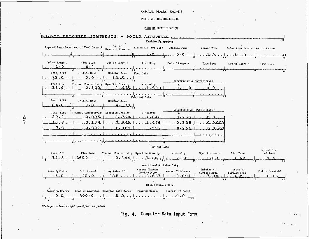
The i n p u t information f o r this second reaction has been entered i n t o a C O ~ D ~ ~ + ~ Y i n p u t data form ( F i g . 4) which i s discussed fur ther i n the next paragrapt-.
-36-
hEM1CAL k4CTOR k Y S l S
PRCG. NO. 406-001-130-000
PROBLEM I DENT I FI CAT ION
* .L - B O Problem Paraneters
M u 8atLh ' Imp Diff I n i t i a l Time F i n i s h Time P r i n t Time Fac to r No. o! Ibrlges No. of
Reactant Const .:( Type of Reaction* No. o f Feed Const.*
4L. , ' * I 0 , * 11.. , , , * . * 1 5 0 6 0 7 0 8 0
4 c - L L * d O t . 4 0 I . . , .O.-.O. . . I a a .l.*.O* I I . . . l . O - . . Q . . 1 . I O 2 0
Time S t e p End o f Range 2 Time S t e p End of Range 3 T i m e S t e p Cnd o f Range I, Time ',tell End of Range 1
I l n 8 . 1 l--LA-A..-.-J*.- I . I . 1 I . . I , , . I * . . I , , . , , I . , , 0.0. , , I I , , , 0...1. , , 1 , , , , , , , , I d ,.d Temp. (OF) 1 0 I n i t i a l Mass 2 0 Maximwn Mass 1 0 Feed Data
3 1 0 8 0
____ 1 I ,7t2,.,0, I 8 I * 0 I ,Oo.,Oo I I I I 9 o1131 e050 t I
I 1 0 2 0 3 0 SPECIFIC HEAT COEFFICIENTS
I . .3.6,..9. . , I I , I .O,.,l,O,O, I , , , , 1,..6,7,5, I I I , , i . . , ~ ~ a I . , , .o. ..2,LO. I I I I , o,..o, , , I . . . l I I I I I I I I I 1 l I I I , I 1 l I L I I , I . I I I I I , , , , , I , l l l , , , , , ~
Feed Rate Thermal Conduct ivi ty S p e c i f i c Grav i ty Vi scos i ty A B
I &&ant D I 1 0
Temp. (OF) I n i t i a l Mass Maxbum Mass I I I ,8,4.,0. . I I I I I ,O.-.O. . I . I I .4,..lJJJJ
I O 2 0 3 0 SPECIFIC HEAT COEFFICIENTS
Comp. Mass Thermal Conduct ivi ty S p e c i f i c Grav i ty Vi scos i ty A B I . w U I
0
Coolant Data S p i r a l Did
of Tube D i d . Tube Temp (OF) Flow Rate T h e r m a l Conduct ivi ty S p e c i f i c Grav i ty V i s c o s i t y S p e c i f i c Heat
I .'6.0.0* . ' ' * I ' ' . * O . * * 3 A 4 . ' . ' ' ' * * ' .2.a3.6* a . * * ' . *o.&LL * . ' . L2"-*q. ' ' 2 0 3 0 4 0 5 0 6 0 7 0 B O
Vessel and A g i t a t o r Data -% . 110
Pdddle Constant Agitator RPM Vessel Thermal I n i t i a l HT De l t a til' Sur face Area Sur face Area Dia. Ag i t a to r Dia. Vesse l Conductivity Vessel Thickness
1 . . .6...0. . . I . . .2&.0. . . 1 . .L&R I I . . I . . .0.&7. I
Mlscel 1 aneous Data
. . .0..,0.9.4. I - , . .7&. . I . . . O d . . . . 1 . . . O . - B L J 2 0 3 0 4 0 s o 6 0 7 0 n o l o .
React ion Energy Heat of React ion React ion Rate Const . Program Const. O v e r a l l HT Const .
I . .o.*.o: . I .aaa-.o. * ' I * ' * .o.-.o. ' . 1 1 * a ' 6 ' I I a .o.-.o. * 1 2 0 3 0 4 0 S O
1 1 0
*Integer vatuee ( r i g h t j u s t i f i e d i n f ieW
Fig. 4. Computer Data Input Form ,
. p .
. .
5.2 PROGRAA INPUT' DATA
The batch s i ze chosen for the example reaction will yield a theoretical maximum yield of 22.05 lb (10 k g ) of picryl chloride. Since the P0Cl3 is known t o react i n a violent, highly exothermic manner, the POCl3 i s added into the pyridinium picrate - DMF solution a t a slow, metered rate . Water cooling is used t o maintain safe reaction temperatures i n the batch.
5.2.1 Problem Identification
T h i s i n p u t ident i f ies the picryl chloride synthesis and the POC13 addition.
5.2.2 Problem Parameters
The type of reaction has been selected as a f i r s t order reaction (ITYPE = 1) since the POC13 feed reactant i s very reactive and is metered slowly i n t o the batch. Three-batch constituents have been entered i n the data since the thermodynamic properties of picr ic acid and pyridine have been included i n the data i n place of the unknown properties of pyridinium picrate. time i n p u t data and calculation interval a re arbi t rary based on the known or estimated reaction time.
The
5.2.3 Feed Data
The POC13 i s the only feed constituent. The t o t a l feed will be 13.5 l b a t room temperature ( 7 2 F ) . This feed mass i s more than t h a t required for the s to i - chiometric reaction so t h a t the reaction i s driven towards completion and good yield i s obtained. The feed ra te is metered slowly a t 36.9 l b / h r . dynamic properties for the POC1, a re entered i n engineering un i t s .
Thermo-
5.2.4 Reactant Data
The pyridinium picrate reaction is exothermic and , as a r e su l t , the batch temperature i s about 84 F when the POC13 addition i s s tar ted. mass entered here is the stoichiometric mass for the POC13 of 4.170 lb. For the second order reaction, the picric acid i s entered as the f i r s t component of the reactant batch. pyridine are also entered.
The maximum
The masses and thermodynamic properties of the DMF and
5.2.5 Coolant Data
Water has been used as a coolant i n the reactor cooling coil w i t h a flow ra te of 3600 lb/hr. Average coolant temperature ( in le t t o out le t p lus time variations) is 72.3 F . The thermodynamic properties for water have been entered for the cool a n t .
-38-

5.2.6 Vessel' and Agitator Data-
The reaction i s carried o u t i n a 200-liter Corning glass reactor w i t h internal cooling coils. The type of ag i ta tor and heat transfer area for this reaction are indicated i n Table I1 (paragraph 2.3.4) . Also, the wall properties of the glass cooling coi l are indicated i n Table I (paragraph 2.3 .2) .
5.2.7 Miscellaneous Data
For the f i rs t order reaction, the reaction energy and reaction rate constant have been set as zero. The heat of reaction has been estimated a t 800 Btu/ lb- POCl3 based on known values for bond-energy and heats of formation and also, on da ta from previous synthesis batches. The program constant has been estimated a t h = 2.0 from Fig . 8 (paragraph 2.4) w i t h a reaction completion time estimated a t 30 minutes. The overall HT coefficient has been entered as W.0" as an indicator for the program t o calculate this coefficient.
5.3 Program O u t p u t
The print-out of the i n p u t d a t a is presented i n Fig. 5, and of the results i n Fig. 6. A p l o t of the calculated and measured temperature histories is given i n F ig . 7 . included . Data from a previous mathematical solution 111 Is also
Although the calculated curve for batch temperature versus time is not com- pletely similar t o the measured curve, the results for peak temperature and the time a t wh ich this peak occurs are close. The peak temperatures are w i t h i n 2 F and the corresponding times are w i t h i n 0.005 hours. Differences i n the shapes o f the computed and measured temperature curves were attributed t o differences between the actual and calculated heat transfer coefficients, heats of reaction, and reaction rate constants.
The calculated values for the heat transfer coefficients agree w i t h values calculated and measured previously [21. The measured values were sl i g h t l y higher than the calculated values i n t ha t reference. the cool-down slopes i n Fig. 7 , the measured value o f the overall film coefficient for this example is slightly lower t h a n the calculated value since the batch temperature decreases more rap id ly i n the theoretical case than i n the measured d a t a .
However, i n viewing
I
-39-

PKOS. NO. 5-300-1-4-BH-1 i H E M I C 4 L &€ACTOR A Y A L Y S I S
P I C R Y L C H L O R I D E S Y V T H E S I S - PU:L3 4 D D I T I J N 12-14-70 IS1 ORDER
P i U 3 L E M P4RAMETEqS
T Y P E OF YS. OF FEEO '40. OF AEACT M 4 X BATSH I V I T I A L R E A C T I O N C 3 Y S T I T J F N T S Z D Y S T I T U E Y T S TEMP D I F F T I M E
FINISH P R I N T 1 I M E NUMBER O F T I M E F A C T J R T I M E RAYGES
1
T I M E I N T E R V A L
1 3 2.0 0.0 1.0 5 . 1
l I Y E STEP
3 . 1 Y I V
FROM
3 . 3 HR
T O
1.3:) HR
F E E 1 3 A T 4
r E M P D E S F
T t i E 2 MAL 3 E N S I TY C 3 N 3 U C T I V I T Y
I N I T I A L MASS,
YAXIYUM FEED M A S S RATE
, SPEC. HEAT COEF. A 0 .
V I S C O S I T Y
1.503 72. ,3 . 3 13.5 36.9 3.10c 1.675 0.2133 3 . 3
?EA:TANT DATA
I 1 E Y P P DE; F 0 I
16.
I N I T l I L MASS
VISCOSITY SPEC. H E 4 1 COEFe A t3
Y A X I Y J C I C O Y P MASS MASS
T H E R Y A L 1 E V S I T Y C 3 N 5 U C T I V I T Y
4 . 3 4 0 1.476 1.597
9.9 4.170 20.2 116.8 7.0
0.0Y5 1.760 3 .134 5.945 3.097 0.982
3.2503 3.0 3 . 3 3 8 0 0 . 0 0 3 3 0 . 2 5 4 0 0.0033
C 3 0 L A V T OAT4
FLOvl rHERrdrZL O E V S I T Y V I S C O S I T Y S P E C I F I C D I A M R A T E C O N 3 U C T I V I T Y i E A T TUBE
3503. 3.344 1.000 2.360 1 e O 3 G 3.69 I N
TEMP D E S F
72.3
S P I R A L D I A M OF C O I L
12.33 I N
VESSEL AVD A S I T 4 T 3 R D 4 T A
A G I T 4 T O R VESSEL THEqMAL VESSEL I N I T I A L HT DELTA HT PADDLE I E V / Y I N C 3 Y D U C T I V I T Y THIIKNESS SURF AREA S J R F AREA CONST.
188. 0.667 0.994 I N 7.00 303 J a 870
Y I S I E L L 4 V E O U S D A T 4
REACT. R A T E PR3GRAY O V E 2 4 L L COVSTAYT COYSTAYT HT COEF.
0.0 2.00G 0.0
01 4METER A G I T A T O R
5.33 I N
R E A C T I O N ENERGY
3.0
DI AMETEQ VESSEL
23.00 I Y
H E A T 3F R E ACT I OY
800.0
f i g . 5. Input Data for Exanple Problem

T I M E B A l C i T E * P
R A l C H F I L M :OEFFIClEYI
159.162 159.162
C33LAYT F I L ' I C3EFFICIEVT
1325.179 1325.179
OVIP4LL T O T t L *ASS LJLFFIZIEYr FEEO
53.332 3.0 53.332 0.363 53.332 0.739 53.332 1.133 53.332 1.477 53.332 1.865 53.332 2.215 53.332 2 . 523 53.332 2.892 53.332 3.251 53.332 3.633 53.332 4.033 53.332 4.359 53.332 4.733 53.332 5.107 53.332 5.475
4 S l C T E D FEEO * A S S
3.3 3.333
nT SJPF ARE4
3.332 0.512 3.322 3.332 2.342 3.352 3.352 3.373 1.333 3.393 1.133 1.113
7.333 7.3;3
7.373 7.333
1 . 3 3 3
1 . 3 3 3 1 . 3 3 3
1.133
1.333
7.333
7.130
7.333 7.330 7.353
7.353 7.330 7.350 7.333 7.333 7.330 7.333 7.333
7.353
8 4 . 1 83.i 82.3 82.5 8 2 . 2 82.3 81.3 81.3 8 ! . 3 82.1 82.2 82.5 82.3 83.2 83.5 84.) 8 4 . 5 85.1 85.5 85.1
87.L 89.3 83.7. 83.0 93.1 91.3 91.5 92.2 93.3 93.7 94.5 95.2 95.3 95.3 91.5
n5.7
159.162 159.162 159.162
1325.179 1325.179 1325.179 1325.179 1325. 179
3.313 3.>31 1.255 3.397 3.124 3.151 3.211 3.257 3. 335 3. 399 3. 673 3.553 3.539 3.731 3.329 5.331 1.333 1.152 1.275 1.353 1.521
159- 162 159.162 159.162 159.162 159.162 159.162 159.152 159.162 159.162
1325.179 1325.179 1325.179 1325.179 1325.179 1325.179 1325.179 1325.179 1325.179 1325.179 132 5.179 132 5. I79 1325.179 1325.179 1325.179 132 5.179 1325.179 1325. I79 1325.179 1325.179 1325.1?9 1325.179 1325.179 1325.179 1325.179 1325.179 1325.179 1325.179 1325.179 1325.179 1325.179 1325.179 1325.179 1325.179 132 5.179 1325.179 1325.179 1325.179 1325.179 1325.179 1325.179 1325.179 1325.179
1.123 3.133 3.143 3.153 '3.153 1.173 1.133 1.133 3.233 3.213 3.223 3.233 1.243 3.253
3.273 0.233 3.233
3.313
3.333 3.343 3.353 3.353 3.373 3.333 3.333 3.433 1.113 J.423 3.533 3.453 5.153
1.473 3.633 3.633 0.533 3.513 3.523 0.533 3.543
3.251
a . 3 3 3
0.323
3.453
159.162 159.162 159.162 159.162 159. 162 15Y.162 159.162 159.152 159.162 i5Y.lbZ 159.1b2 159.162 159.162 159.162 159.1b2 159.162 159.162 159.162 159.162 159.162 159.162 159.162 159.162 159. kb2 159.162 159.162 159.162 159.162 159.162 159.152 159. I62 159.162 159.162 159.162 159.162 159.162 159.162 159.162 159.162 159.162 159.162 159.162
...... .~ 53.332 5.845 53.332 5.215 53.332 6.534 53.332 5.953 53.332 7.322 53.332 7.592 53.332 3.061 53.332 3 . 4 3 3 53.332 8.799 53.332 9.168 53.332 9.535
1 . 5 5 4 1.791 1 . 3 3 3 2 . 3 8 3
7.35 7.333 7.303 7.333 7.333 7.353 7.353 7.333 7.333
7.330 1.333 7.530 1 . 3 3 3 7.533 7.330 7.333
7.351 7.333 7.333 7.333
7.330
7.333
53.332 9.937 53.332 1C.275 53.332 13.545 53.332 11.014 53.332 11.334 53.332 11.753 53.332 12.122 53.332 12.491 53.332 12.853 53.332 13.233 53.332 13.535 53.332 13.536 53.332 13.535 53.332 13.535 53.332 13.535 53.332 13.535 53.332 13.536 53.332 13.535
2.231 2.385 2.545 2.759 2.377 3. 349 3.224 3.434 3.j87 3.774 3.355 C.155 +.I70 4.173
, 9.173 4.173 6.173 9.173 1.173 4.173 1.173 9.i73 5.173
93;3 93.3 99.3 93.7 97.3 95.3 94.7 93.5 92.4 91 e3 93.3 5 a . 3 89.5 87.5 85.3 85.3 85.3 8 4 . 5 83.3 03.3
82.2 81.5
n2.1
~~~~~~
53.332 i3.535 53.332 13.535 53.332 13.535 53.332 13.535 53.332 13.535
7.333 7.J33 7.333 7.333 7.333
1325.179 1325.179 1325.179 1325*179 1325.179
53.332 13.535 53.332 13.535 53.332 13.535 53.332 13.535 53.332 13.535 53.332 13.535 53.332 13.535
4.173 6.173 1.173 5.173
1.173 L.173 4.173 0.173 i.173 0.173 4.173 6-173 0.173 L. 173 9.171 4.173
(.IT)
7.333 7.333 7.333 7.3;3 7.353 7.333 7.333 7.333
3.553 3.553 3.573 3.593
1325.179 1325.179 1325.179 1325.119 1325.173 1325.179 1325. I19 1325.179 132 5.179
~ ~~ ~
159.162 159.162 159.162
53.332 13.535 j3.332 13.535 5 3 . 3 3 2 13.535 >3.332 13.535 53.332 13.535
7.333 7.335 7.330 7.333 7.333 7.350 7.333 7.353
3.533 3.533 3.513 3.623 3.533 3.503 3.553 3.551 3.573 3.533 3.533 0.733 3.713 0.723
3.753 3.753 1.753
3.733
3 i . l 83.7 83.2 79.3 ? 3 . 4 79.3 78.7 78.3 73.1 77.7 77.4
157.162 1 5 Y . 162 159.162 159.162 159.162 159.162 159.152 159.162 159.162 159.162 159. I62
53.332 13.535 53.332 13.535 53.332 13.535 53.332 13.535 53.332 13.535 53.332 13.535 53.332 13.535 53.332 13.535 53.332 13.535 53.332 13.535
1325.179 1325.119 1325.179 1325.179 1325.179 1325.179 1325.179 1325.179 1325.179 1325.179 1325.179 1325.179 1325.179 1325.179 1325.179 1325.179 1325.179 1325.179 1325.179
7.333 7.330 1.333 7.333 7.333 7.333 7.333
77.1 1 5 . 3 75.5 75.4 75.2 75.3 15.3
159.162 15~. 162 159.162 159.152
L. 173 9.173 4.173 4.173 5.173 1.173 +.I73 C.173 6.173
7.353 7.333
7.303 7.333 7.330 7.330 7.333 7.333 7.333 7.333 7.333 7.303
7.330 159.162 159.152 159.162 159.162 159.162 159.162 159.162 159.162 159.162
5.773
J.793 3.833
3 . 1 3 3 75.5 75.4 75.3 75.1 7 4 . 3 74.3 74.7 74.5 74.4 74.3 74.2 74.1 74.3 73.3 73.3 73.7 73.7 73.5 73.5 73.5
53.332 13.535 53.332 13.535 53.332 13.535 53.332 13.535 53.332 13.535 53.332 13.535 53.332 13.535 53.332 13.535 53.332 13.535 53.332 13.535 53.332 13.536 53.332 13.535 53.332 13.535 53.332 13.535 53.332 13.535
4.173 C.173 6.173 4 , i73 4.173 4.173 4.173 4.175 9.173 k.173 6.173 6.173 6-17> 4.173 4.173 1.173 6.173 6.173 b.170
6.173 1.173
3.913 3.325 3.33) 3 . 3 4 3 3.953 3-85) 3.973 3.333 3.333 3.333 3.313 3.323 3. 333
1.353 3.353 3.973 0.993 3.993 1.333
0.943
159.162 159.162 159.162 159.162 159.162 159.162 159. 162 159.162
:::::g 159.162 159.162 159.162 159.162 159.162 159.162 159.162 159.162
1325-179 1325.179 1325.179 1325.179 1325.179 1325.1 79 1325.179 1325.179 1325.179 1325.179 1325.179 1325.179 1325.179 1325.179 1325.179 1325.179 1325.179 1325.179
1.330 7.333 7.303 7.330 7.333 7.333 7.333 7.300 7.333
7.33) 7.333
1.333 1 .333
7.133
7.330
~~ ~~
53.332 13.535 53.332 13.535 53.332 13.535 53.332 13.535 53.332 13.535 ~.~
73.4 73.3 73.3
53.332 13.535 53.332 13.535 53.332 13.535 53.332 13.535 73.2
R E L 4 l I V E MINIMUM 84TCH TEMP OF 81.9 JCCUISfD A T 5.367 i R S . *CLAIIVE II~XIWM srrcn TEMP OF 99.9 a c c u w o 4r 0.383 IRS.
Fig. 6. Results for Example Problem
-41 -

- . .
100
90
n LL W
7c
Mathematical Solution [11 , Constant Reaction Rate i-
\ Theoret ical , TCHREACT s \./ Firs t -order , RCON=2.0
\
Average coolant temperature
t I I I I I I I I I I
Time (hours) I 0.5 1 .o
Fig. 7. Theoretical and Measured Batch Temperatures vs . Time Picryl Chloride Synthesis, POCl Addition Reaction
-42-

6.0 CONCLUSIONS
TCHREACT has been verified for a 1 imi ted number of representative reactions by comparison of program resul ts wi’th measured data. Additional experience may disclose l imitations i n the program and will undoubtedly lead t o require- ments for revisions.
The selection of the proper order of the reaction and the-determination o f the heat-of-reaction and reaction ra te constant values for-use i n the program i s d i f f i c u l t for many reactions where much of this data i s not-available. The order of the reaction can be determined from the l i t e ra ture-or past.experience. The heat-of-reaction can be estimated from bond-energies-and known heats of formation, b u t the result ing value is subject t o s ignif icant error. the reaction r a t e constant can be estimated from d i s t r i b u t i o n functions for bimolecular reactions or from integration of the r a t e equation w i t h known Yalues of temperature or concentration a t a p o i n t i n time. In addition, a l l of these reaction parameters ( the order of the reaction, heat-of-reactions, and reaction r a t e constant) can be determined experimentally from laboratory measurements of concentration and temperature versus reaction time.
Also,
A t the present, l a t t e r experimental approach i n the 1aboratory.appears t o be the most trustworthy method of obtaining rel iable parameters>for the program which will y ie ld the accurate estimates of the temperature- rise-during .a large batch reaction. These computed resul ts must be f a i r l y accurate i f the program i s t o be of value i n predicting h i g h temperature, dangerous operating conditions. In the near future , a follow-on effort i s planned t o develop one or two additional computer programs f o r analytically determining the heat-of-reaction and the re- action ra te constant.
-43 -

1.
2.
3.
4.
5 .
6.
7.
8.
9.
7 .O REFERENCES
F. I . Honea, Chemical Reactor Analyses - Exothermic Reaction, Mason & Hanger - Si l a s Mason Co. , Inc. , Acct. No. 22-2-44-00-221 (July 1970).
F. I . Honea and D. V. Hayes, Heat Transfer Coefficients f o r Chemical Reactors, Mason & Hanger - Silas Mason Co., Inc., Acct. No. 22-2-44- m A u g u s t 1970).
John H . Perry, Chemical Engineer's Handbook, 4th Edition, McGraw-Hill (1963) .
The Pfaudl er Company , B u l l e t i n 1029.
Max Jacob, Heat Transfer, Volume I , John Wiley and Sons (1949).
R. B. B i rd , W . E. Stewart, and E . N. Lightfoot, Transport Phenomena, John Wiley and Sons (1960).
V . C. Marshall and N . Yazdani , "Design of Agitated, Coil-in-Tank Coolers," Chemical and Process Engineering (Apri 1 1970) . E . A . Moelwyn-Hughes, The Kinetics of Reactions i n Solutions, Oxford a t the Clarendon Press , 2nd Ed. (1947).
D. V . Hayes and F. I . Honea, Synthesis of Picryl Hydrazine, Mason & Hanger - Si las Mason Co., Inc., P.O. 93-1840, ( A u g u s t 1970).
-44-


