Page 1
1/13
Oel-Waerme-Institutan derAffiliated institute of the
Reactor development for a steam reforming fuelprocessor for diesel fuel in the kW range
Marius Maximini1, Philip Engelhardt1, Martin Brenner2,Andrea De Toni3, Hans-Georg Anfang3
1Oel-Waerme-Institut GmbH, Germany2 BEHR GmbH & Co. KG, Germany
3Süd-Chemie AG, Germany
Berlin, 12.04.2012
Page 2
2/13
Oel-Waerme-Institutan derAffiliated institute of the
Outline
Project introduction and background
Reactor development for mixture preparation
Reformer development and testing
Summary
Page 3
3/13
Oel-Waerme-Institutan derAffiliated institute of the
Introduction
MÖWE 2 ProjectDevelopment of an integrated fuel cell system comprising a 10 kWth diesel fuel processorand a 4 kWel LT-PEM fuel cell
Diesel fuel High availability, existing infrastructure easy market entry High energy density compact size Easy storage
Steam reforming Highest hydrogen yield of all reforming processes No dilution of reformate gas with atmospheric N2
LT-PEM fuel cell Technical maturity High availability
Market: APU for recreational applications
Page 4
4/13
Oel-Waerme-Institutan derAffiliated institute of the
Introduction
Modular fuel cell system fuel processor adaptable for LT-PEM and HT-PEM fuel cells
Page 5
5/13
Oel-Waerme-Institutan derAffiliated institute of the
New multifunctional reactor (Prototype developed with J. Eberspächer GmbH & Co. KG)
Start-up burner
Cool Flame reactor for fuel evaporation
Diesel / steam mixer
Operation: Start-up burner + Diesel/steam mixer
on reformer side
Start-up burner + Cool Flame reactor on burner side
Electrical heating for Cool Flame and mixer operation
Reactor development
T2
Porous surfaceT1
Air / H2O
Diesel
T3
Electrical heating
Page 6
6/13
Oel-Waerme-Institutan derAffiliated institute of the
Burner operation Characteristics for safe ignition
determined
Fuel input can be increased after ignition
Operation shown for fuel inputs up to 3 kWth
Flame stabilizes in the reactor front
Air excess ratio may be increased for lower outlet temperatures less thermal stress on the reformer
Reactor development
Start-up burner, ignition
0.0
0.5
1.0
1.5
2.0
2.5
3.0
3.5
0.0 0.5 1.0 1.5 2.0 2.5 3.0
Fuel input / kW
Air
exce
ss ra
tio
ignition successful
Burner operation, temperatures at = 2.5
700
800
900
1000
1100
1200
1 1.5 2 2.5 3 3.5Fuel input / kW
Tem
pera
ture
/ °C
T 1
T 2
T 3
T2
T1
T3
Page 7
7/13
Oel-Waerme-Institutan derAffiliated institute of the
Cool flame start-up procedure, target temperature T1 = 420°C
0
200
400
600
800
1000
1200
00:00 00:05 00:10 00:15 00:20Runtime / hh:mm
Tem
pera
ture
/ °C
0
2
4
6
8
10
12
Fuel
inpu
t / k
W,
air e
xces
s ra
tio
Pfuel
T1
T2
T3
Steady state cool flame operation
0.0
0.1
0.2
0.3
0.4
0.5
0.6
0.7
0.8
0.9
1.0
410 420 430 440 450 460 470Temperature at T1 / °C
Air
exce
ss ra
tio
1 kW 1,5 kW 2 kW 2,5 kW 3 kW
Temperature control by air excess ratio
Steady state operation shown at 1 – 5 kWth
Cool flame operation Preheating in burner mode
Cooling down to cool flame temperature level
Start of the cool flame reaction at an air excess ratio < 1
Reactor development
T2
T1
T3
Page 8
8/13
Oel-Waerme-Institutan derAffiliated institute of the
0
2
4
6
8
10
12
00:00 00:30 01:00 01:30 02:00 02:300
200
400
600
800
1000
1200Electrical heating
runtime / hh:mm
TReformer, Pos.6
Pel
PCool flame
PReformer
el. P
ower
, fue
l inp
ut /
kW
Tem
pera
ture
/ °C
Cool flame Reformer start
Deployment of the reactor in the 10 kWth fuel processor Reduction of FP start-up time > 60 % by using one multifunctional reactor as Cool
Flame reactor instead of electrical heating device
Minimal electric power consumption
Start-up time < 30 min expected when deploying a second reactor for diesel/steam mixing
(based on experimental data from P.Engehardt, 2012)
Reactor development
0
2
4
6
8
10
12
00:00 00:30 01:00 01:30 02:00 02:300
200
400
600
800
1000
1200
runtime in hh:mm
T Reformer, Pos.6
PCool flame
Fuel
inpu
t / k
W
Tem
pera
ture
°C
T
Cool flame
Start-up Burner
Reformer start
PReformer
Page 9
9/13
Oel-Waerme-Institutan derAffiliated institute of the
Reformer development on downscaled steam reformers Catalytically coated plate heat exchanger
Microchannels with 0.6 mm channel height
Scaling by plate number reduction, original plate size
Design point of Pth = 1 kW at GHSV = 25,000 h-1
Reformer testing Süd-Chemie HyProGenTM catalyst coating
Steamreforming
Combustion
Temperature measurement plate
1
2 4
5
6
8
7 9 10 11Flowdirection
3
Steam reformingCombustion
Reformer development
Page 10
10/13
Oel-Waerme-Institutan derAffiliated institute of the
Test program Variation of
steam to carbon ratio (S/C),
operating temperature,
and fuel input
Reforming of Diesel surrogate (Shellsol mixture)
Reforming of commercial diesel (Shell petrol station)
Catalyst testing
Diesel surrogateMixture of ShellSol A 100 + ShellSol D 100
SMS 1897< 2 wt.ppmSulphur
SMS 272820 wt.%Aromatics
GC32 wt.%Naphtenes
GC48 wt.%Paraffins
Method of analysisValueFraction
Commercial diesel (ULSD)Shell
DIN EN 1291621.1 wt.%Aromatics
DIN EN 140786.4 vol.%FAME
DIN EN ISO 208466.4 wt.ppmSulphur
ASTM D 5291 mod.1.3 wt.%Oxygen
DIN 51 73213.5 wt.%Hydrogen
DIN 51 73284.5 wt.%Carbon
Method of analysisValueFraction
Page 11
11/13
Oel-Waerme-Institutan derAffiliated institute of the
Gas concentrations, diesel surrogate, Pth = 1.25 kW
0
10
20
30
40
50
60
70
2 2.5 3 3.5 4 4.5S/C
Con
cent
ratio
ns /
% v
/v
(dry
bas
is)
0
3
6
9
12
15
18
21
Con
cent
ratio
ns /
% v
/v
(dry
bas
is)
Temperature T6 = 700°CTemperature T6 = 800°C
CO2
CO
H2
CH4
Catalyst testing
Diesel surrogate reforming No diesel residues found by GC analysis (CH4 and CO2 are the only by-products found)
Complete fuel conversion achieved over the entire parameter range
Page 12
12/13
Oel-Waerme-Institutan derAffiliated institute of the
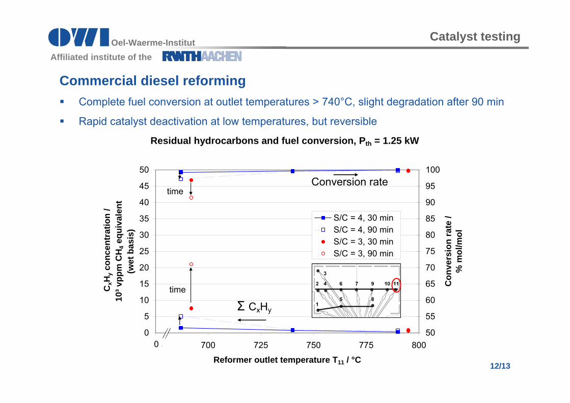
Residual hydrocarbons and fuel conversion, Pth = 1.25 kW
0
5
10
15
20
25
30
35
40
45
50
675 700 725 750 775 800
Reformer outlet temperature T11 / °C
CxH
y con
cent
ratio
n /
10³ v
ppm
CH
4 equ
ival
ent
(wet
bas
is)
50
55
60
65
70
75
80
85
90
95
100
Con
vers
ion
rate
/ %
mol
/mol
S/C = 4, 30 min S/C = 4, 90 minS/C = 3, 30 minS/C = 3, 90 min
0
Conversion rate
Σ CxHy
time
time
Catalyst testing
Commercial diesel reforming Complete fuel conversion at outlet temperatures > 740°C, slight degradation after 90 min
Rapid catalyst deactivation at low temperatures, but reversible
Page 13
13/13
Oel-Waerme-Institutan derAffiliated institute of the
Coke / carbon formation, Pth = 1.25 kW
0
10
20
30
40
50
60
70
80
90
100
675 700 725 750 775 800Reformer outlet temperature T11 / °C
carb
onac
eous
dep
osits
/ m
g/kW
h
Diesel S/C = 4Diesel S/C = 3Diesel surrogate S/C = 4Diesel surrogate S/C = 3
Catalyst screening
Commercial diesel reforming Coke / carbon formation increased using commercial diesel compared to diesel surrogate
Low temperatures and low S/C increase the effect
Page 14
14/13
Oel-Waerme-Institutan derAffiliated institute of the
GC analysis, 10 h steam reforming of commercial diesel at T6 = 750°C , S/C = 4, Pth = 1.25 kW, GHSV = 31,000 h-1
0
1
2
3
4
5
6
1:00 2:00 3:00 4:00 5:00 6:00 7:00 8:00 9:00 10:00
runtime / hh:mm
Con
cent
ratio
ns /
10³ v
ppm
(d
ry b
asis
)
0
0.1
0.2
0.3
0.4
0.5
0.6
Con
cent
ratio
ns /
10³ v
ppm
(d
ry b
asis
)
CH4C2H6C2H4C3H8C3H6C4H10C5H12
CH4
Aromatic residuals in the reformate
Commercial diesel reforming Selectivity suffers from catalyst deactivation
Hydrocarbon concentrations increase due to progressing catalyst deactivation
Catalyst testing
Page 15
15/13
Oel-Waerme-Institutan derAffiliated institute of the
Commercial diesel reforming Progression of temperature profiles in the reformer
Shift of the main reaction zone through the reformer due to catalyst deactivation
Temperature profile reformer center
700
720
740
760
780
800
820
840
0 20 40 60 80 100 120 140Distance form reformer inlet / mm
Tem
pera
tur i
n °C
00:30 h
03:30 h
06:30 h
09:30 h
time
time
Temperature profile reformer periphery
700
720
740
760
780
800
820
840
0 20 40 60 80 100 120 140Distance from reformer inlet / mm
Tem
pera
ture
/ °C
00:30 h
03:30 h
06:30 h
09:30 h
time
time
2 4 6
7 910
11
1
5
8
Catalyst testing
Page 16
16/13
Oel-Waerme-Institutan derAffiliated institute of the
SummaryReactor development
Multifunctional reactor for mixture preparation has been developed and characterised
Deployment of one reactor leads to FP start-up time < 45 min,
Potential start-up time < 30 min when using a second reactor
Catalyst testing
Süd-Chemie HyProGenTM shows complete fuel conversion in reforming diesel surrogate
Complete fuel conversion achieved in reforming commercial diesel at outlet temperatures > 740 °C
Increased catalyst deactivation from carbon/coke formation and sulfur poisoning in reforming commercial diesel, deactivation is reversible
Catalyst deactivation leads to a progression of the temperature profile inside the reformer
Summary
Page 17
17/13
Oel-Waerme-Institutan derAffiliated institute of the
Thank you for your attention!
Contact:
Dipl.-Ing. Marius MaximiniOWI Oel-Waerme-Institut GmbHAffiliated Institute of RWTH-AachenKaiserstrasse 10052134 HerzogenrathTel: +49 (0) 2407 / 9518-176Mail: [email protected]
Acknowledgement:
Funding by the
German Federal Ministry of Economics and Technology (BMWi)
Project MÖWE II, FZK: 0327724