For convenience this document uses short names when referring to a particular system or kit. The list below identifies the short names used herein: Remote Start System > RMST
Navigating this document can be accomplished by: 1) using the buttons in the Acrobat toolbar or 2) clicking on the bookmark links in the bookmark pane to the left. (Clicking on the (+) symbols next to a bookmark will expand that bookmark, revealing additional selections).
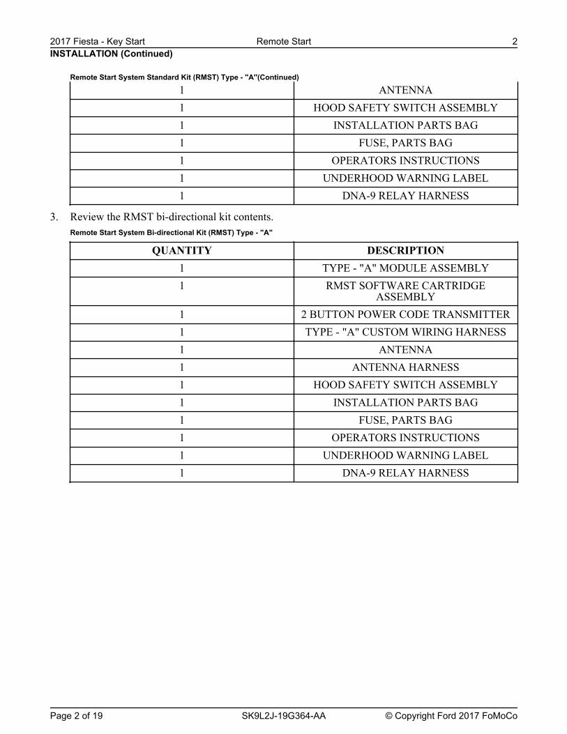
This installation instruction covers the installation of all Remote Start Kits.
Vehicle wiring is subject to change. All possible efforts have been taken to ensure that the information contained herein is accurate as of the revision dates indicated. As such, it is critical that vehicle circuits are tested prior to making any connections, to ensure that the proper vehicle circuit has been located.
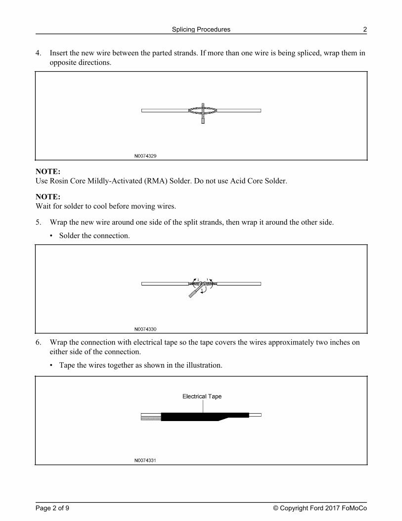
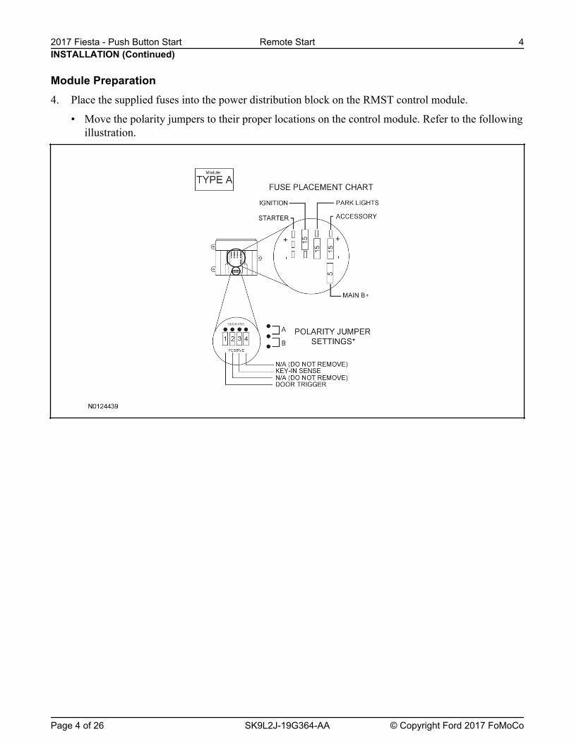
Prior to beginprevent locking the keys in the vehicle.Prior to beginning your first installation of this product it is recommended that you:
1. Thoroughly review and print out the instructions; 2. Review the reference section to become acquainted with the additional information that is available. 3. Go through the vehicle specific wiring and use as a reference during the installation.4. Review the installation video on the Ford Genuine Accessory website that is located with the RMST Installation Instructions.
Ford Accessory Vehicle Security, Keyless Entry and Remote Start
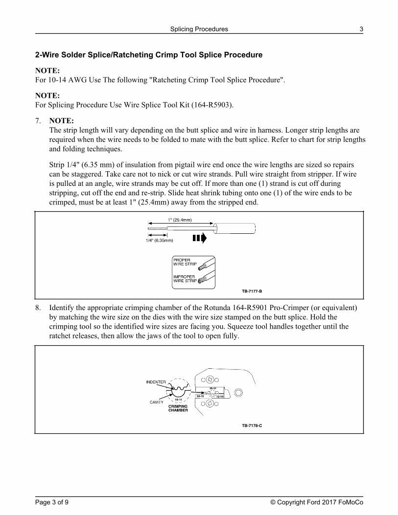
Warranty Return Procedures
DO NOT CLAIM PARTS WARRANTY ON FORM 1863 Parts Warranty Processing: Lifetime limited coverage to original purchaser on all components against defects and workmanship. (For complete Warranty details, please refer to the warranty section found at the rear of each Security or Remote Start systems Owners Manual) Contact the warrantor, Code Systems for return authorization/replacement approval for failed components at no charge by the manufacturer. Return of Components to Code Systems requires the following:
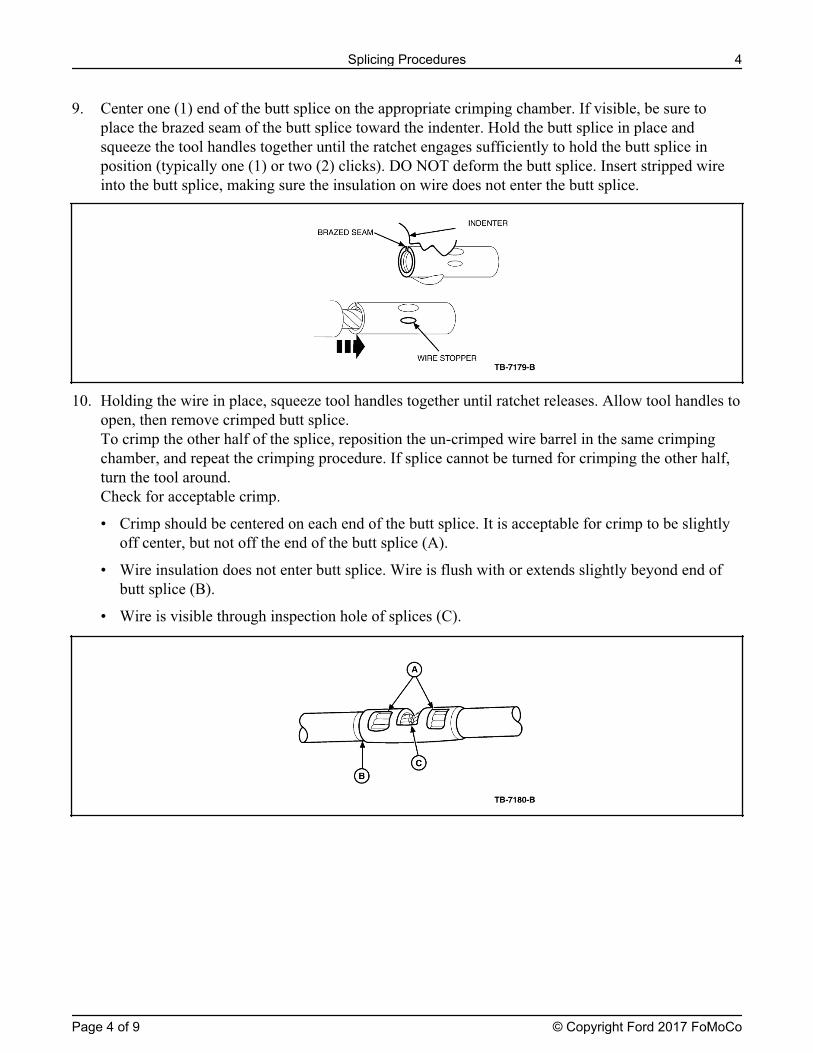
1. Dealer/FAD representative must call the Ford Vehicle Security System Dealer Warranty Department at 1-800-FORDKEY (1-800-367-3539) to obtain generic claim form.
2. Fill out claim form and identify the defective component, not the entire kit, and fax to 1-631-231-5785.
3. Dealer/FAD will receive via fax the claim form with RA number authorizing the return of defective components.
4. Dealer/FAD is to box the defective component (including a copy of the claim form) with the claim number clearly written on the package(s) and ship them freight pre-paid to:
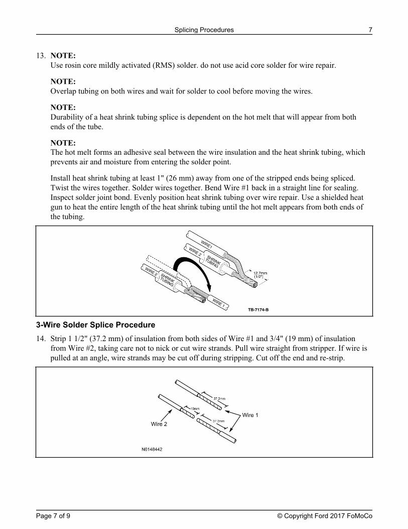
Ford Service Parts 180 Marcus Blvd.
Hauppauge, NY 11788
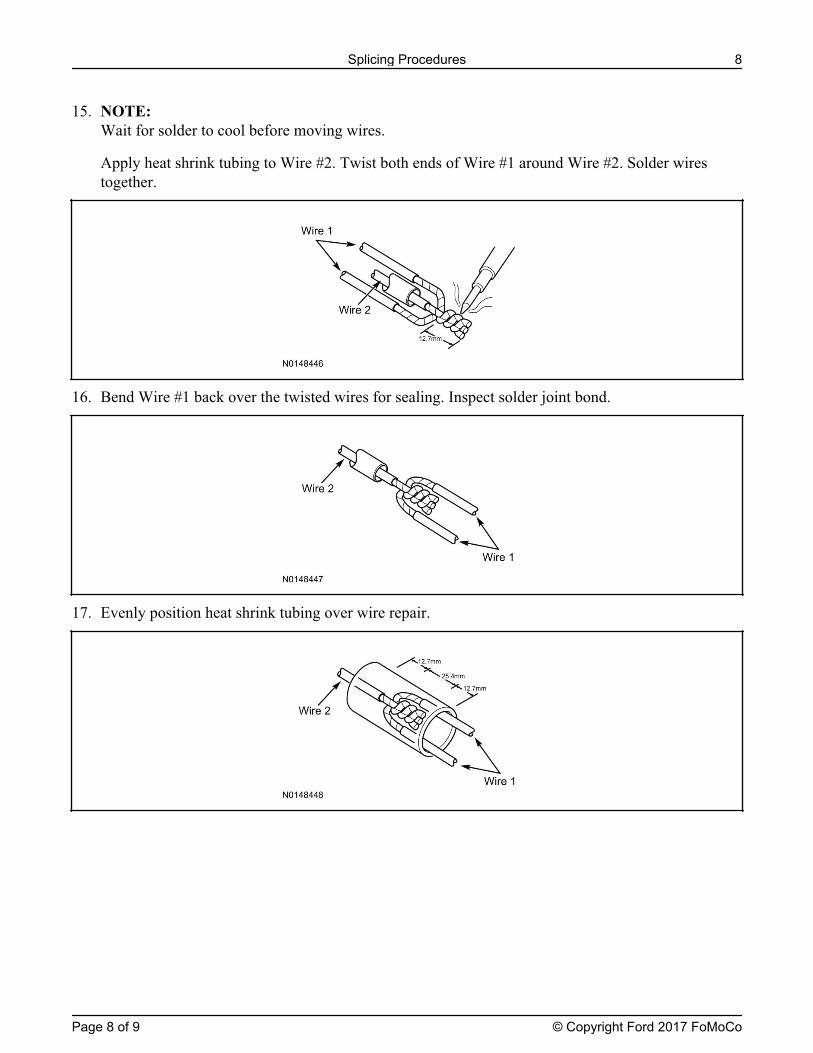
Note: If the package is sent without a claim number/claim number visible on the outside of the package, the shipment will be refused and returned at sender’s expense.
5. Once a tracking number for the returning component has been issued to Code
Systems, replacement components will be shipped within 24 hours via regular UPS ground transportation.
6. Dealer/FAD is responsible for service parts not returned/received by the Warranty Service Center within 30 days of the original claim date. Post the 60 days; the Dealer/FAD will be liable for all non-returned components at service part pricing.
Removal and reinstallation labor may be reimbursable under the New Vehicle Limited Warranty or 12-month/12,000 mile warranty (which ever is greater) and must be submitted by filling a warranty claim through ACES II.
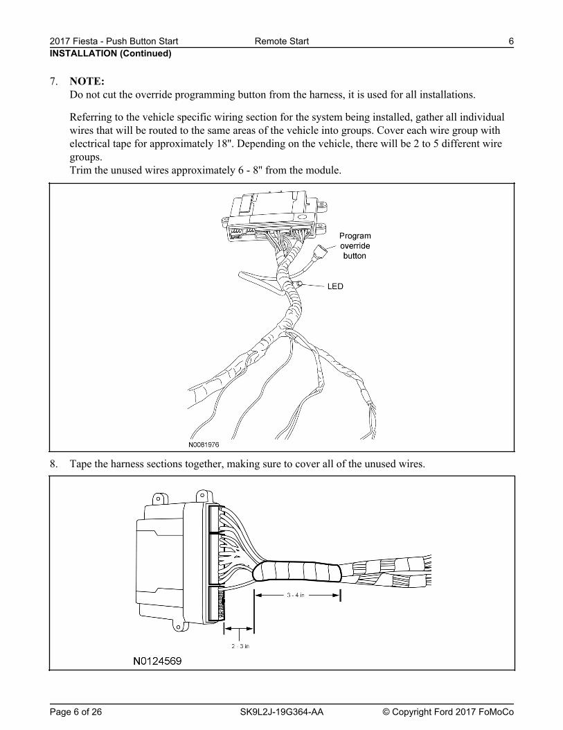
7. NOTE: Do not cut the override programming button from the harness, it is used for all installations.
Referring to the vehicle specific wiring section for the system being installed, gather all individualwires that will be routed to the same areas of the vehicle into groups. Cover each wire group withelectrical tape for approximately 18''. Depending on the vehicle, there will be 2 to 5 different wiregroups.Trim the unused wires approximately 6 - 8'' from the module.
8. Tape the harness sections together, making sure to cover all of the unused wires.
Vehicle Preparation9. Remove the retainers and the upper and lower steering column shrouds.
10. Open and remove the glove box.
11. Remove the RH lower instrument panel insulator.
12. Using a suitable non-marring tool, work around the outer edge of the headlamp switch to release theclips and pull the switch out through the front of the finish panel.
• Disconnect the electrical connector.
13. Install the supplied wire harness label to the headlamp switch harness.
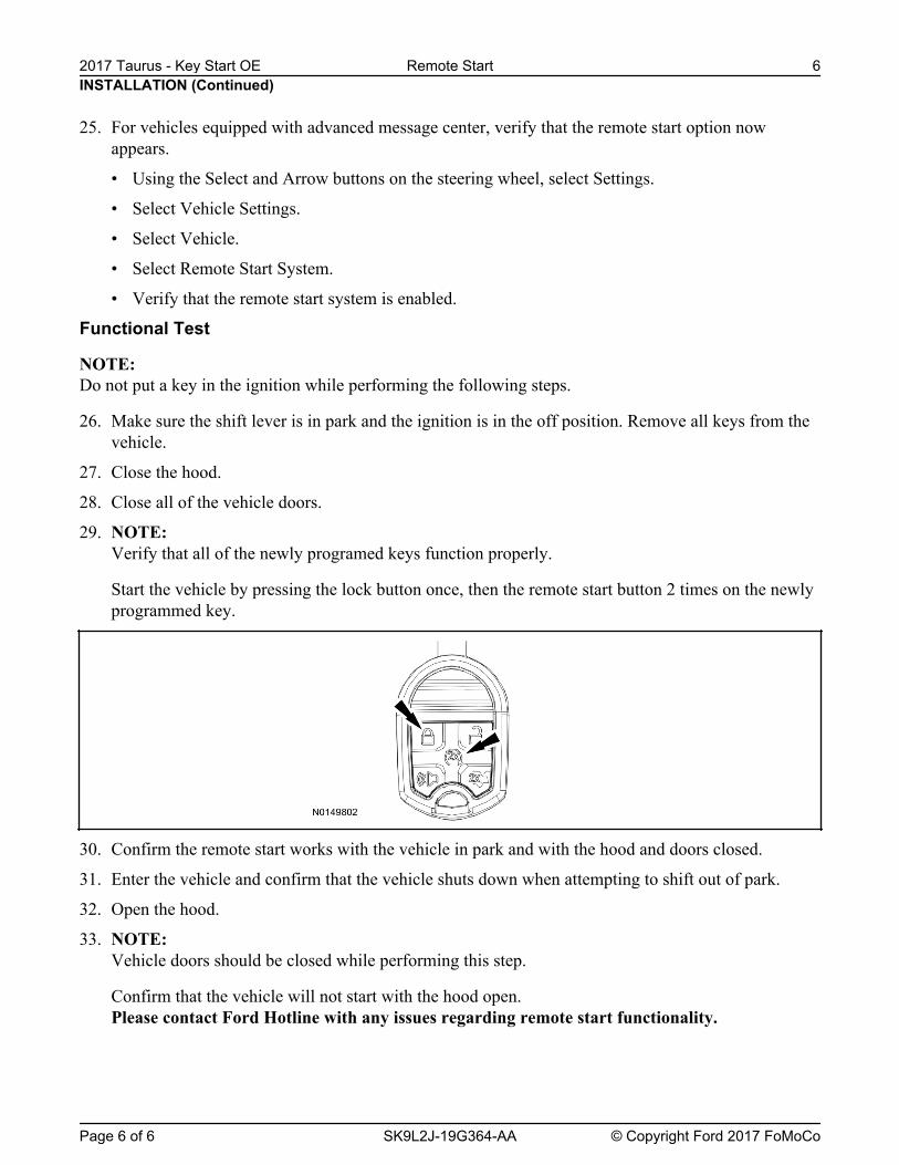
• If required, fish the headlamp switch wire harness out of the instrument panel.
14. Connect and Install the headlamp switch.
15. Remove the start/stop switch. For additional Information, refer to Workshop Manual (WSM),Section 211-05.
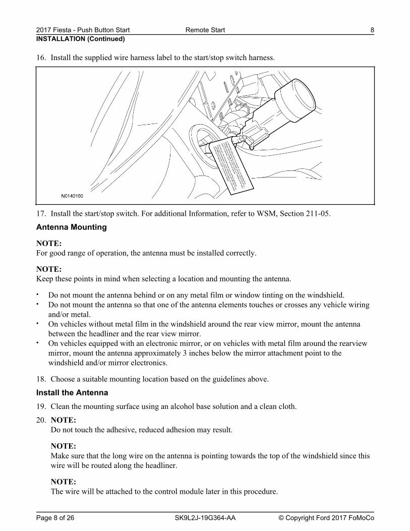
16. Install the supplied wire harness label to the start/stop switch harness.
17. Install the start/stop switch. For additional Information, refer to WSM, Section 211-05.
Antenna Mounting
NOTE: For good range of operation, the antenna must be installed correctly.
NOTE: Keep these points in mind when selecting a location and mounting the antenna.
• Do not mount the antenna behind or on any metal film or window tinting on the windshield.• Do not mount the antenna so that one of the antenna elements touches or crosses any vehicle wiring
and/or metal.• On vehicles without metal film in the windshield around the rear view mirror, mount the antenna
between the headliner and the rear view mirror.• On vehicles equipped with an electronic mirror, or on vehicles with metal film around the rearview
mirror, mount the antenna approximately 3 inches below the mirror attachment point to thewindshield and/or mirror electronics.
18. Choose a suitable mounting location based on the guidelines above.
Install the Antenna19. Clean the mounting surface using an alcohol base solution and a clean cloth.
20. NOTE: Do not touch the adhesive, reduced adhesion may result.
NOTE: Make sure that the long wire on the antenna is pointing towards the top of the windshield since thiswire will be routed along the headliner.
NOTE: The wire will be attached to the control module later in this procedure.
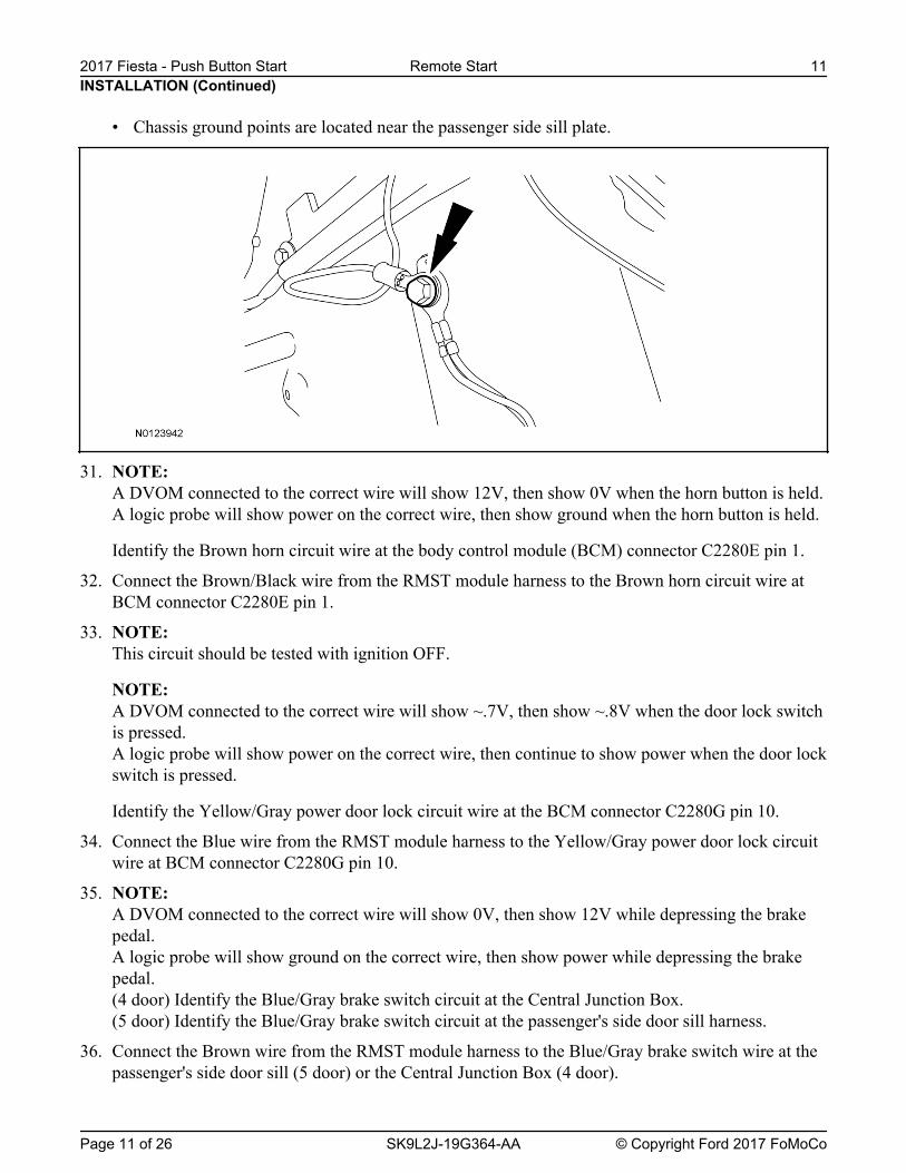
• Chassis ground points are located near the passenger side sill plate.
31. NOTE: A DVOM connected to the correct wire will show 12V, then show 0V when the horn button is held.A logic probe will show power on the correct wire, then show ground when the horn button is held.
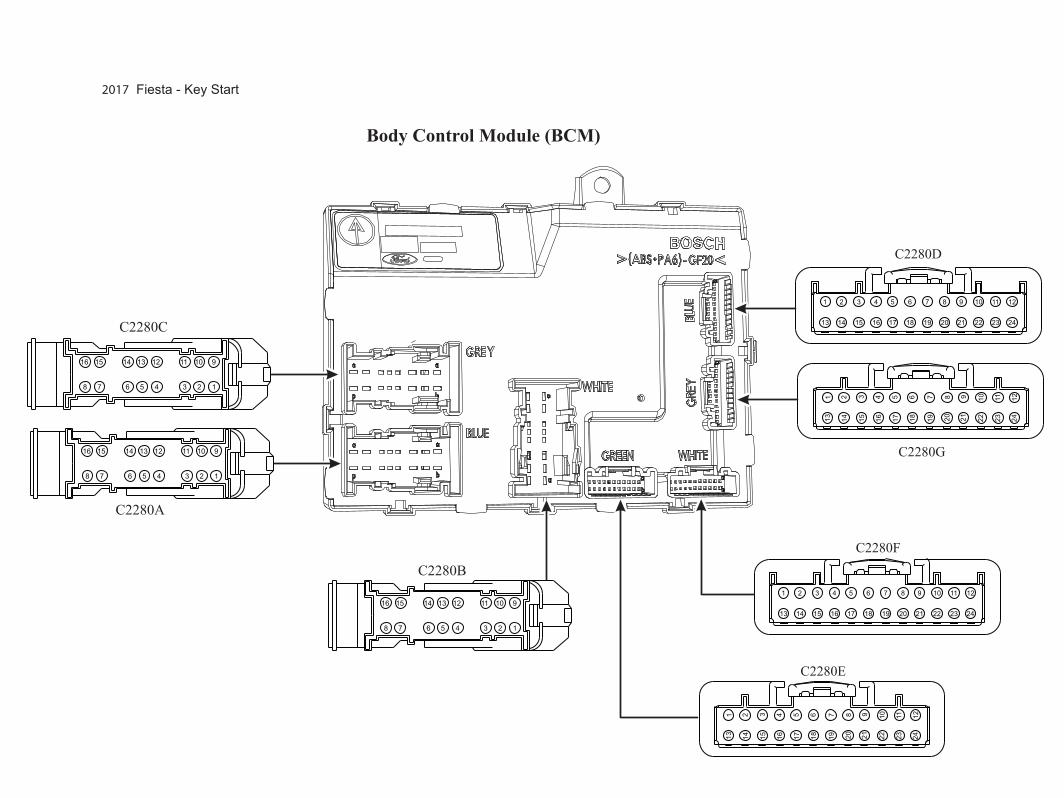
Identify the Brown horn circuit wire at the body control module (BCM) connector C2280E pin 1.
32. Connect the Brown/Black wire from the RMST module harness to the Brown horn circuit wire atBCM connector C2280E pin 1.
33. NOTE: This circuit should be tested with ignition OFF.
NOTE: A DVOM connected to the correct wire will show ~.7V, then show ~.8V when the door lock switchis pressed.A logic probe will show power on the correct wire, then continue to show power when the door lockswitch is pressed.
Identify the Yellow/Gray power door lock circuit wire at the BCM connector C2280G pin 10.
34. Connect the Blue wire from the RMST module harness to the Yellow/Gray power door lock circuitwire at BCM connector C2280G pin 10.
35. NOTE: A DVOM connected to the correct wire will show 0V, then show 12V while depressing the brakepedal.A logic probe will show ground on the correct wire, then show power while depressing the brakepedal.(4 door) Identify the Blue/Gray brake switch circuit at the Central Junction Box.(5 door) Identify the Blue/Gray brake switch circuit at the passenger's side door sill harness.
36. Connect the Brown wire from the RMST module harness to the Blue/Gray brake switch wire at thepassenger's side door sill (5 door) or the Central Junction Box (4 door).
A DVOM connected to the correct wire will show 0V with the vehicle door(s) open and the domelight ON, then show 12V with the vehicle door(s) closed and the dome light OFF.
NOTE: A logic probe connected to the correct wire will show ground with the vehicle door(s) open and thedome light ON, then show power with the vehicle door(s) closed and the dome light OFF.
NOTE: Be sure that the dome light has timed out and is OFF before performing the door closed test.Be sure that the dome lamp is illuminated before performing the door open test.
Identify the Yellow/Gray dome light circuit wire at the BCM connector C2280C pin 5.
38. Connect the Green/Violet wire from the RMST module harness to the Yellow/Gray dome lightcircuit wire at the BCM connector C2280C pin 5.
39. NOTE: A DVOM connected to the correct wire will show ground with the headlamp switch in the OFFposition, then momentarily show 10~11V with the headlamp switch in the parking lights ONposition.
NOTE: A logic probe will show power with the headlamp switch in the ON position and ground with theswitch in the OFF position.
Identify the Yellow/Blue parking lights circuit wire at the BCM connector C2280F pin 23.
40. Connect the White wire from the RMST module harness to the Yellow/Blue parking lights circuitwire at the BCM connector C2280F pin 23.
41. NOTE: A DVOM connected to the correct wire will show ground (0V) then show power (12V) with thebrake pedal depressed.
NOTE: A logic probe will show ground and then power with the brake pedal depressed.
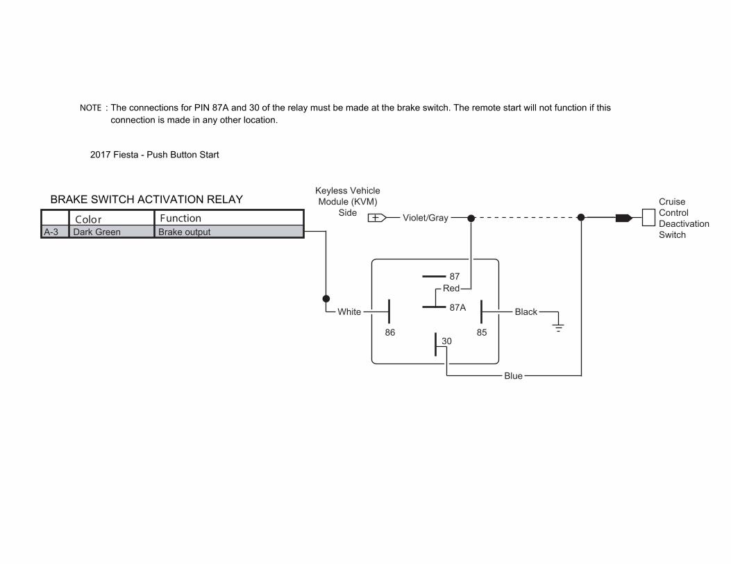
Identify the Violet/Gray cruise control deactivation switch circuit wire located next to the brakeswitch (vehicle has two independent brake pedal switches).
42. Remove the circuit 87 Yellow wire and terminal from the relay harness connector.
• Release the locking tab and pull the wire and terminal from the connector.
• Discard the Yellow wire, it will not be used for this application.
43. Install a suitable insulated crimp terminal eyelet to the Black interrupt relay wire. Attach the Blackrelay wire to a suitable grounding location.
44. Connect the Dark Green wire from the remote start module harness to the White wire at the relayharness.
Be sure to leave enough wire at each end of the cut wire to properly splice the relay wire leadingback to the cruise control deactivation switch harness.
Cut the Violet/Gray brake pedal switch wire previously identified in step 41.
• Connect the Blue wire from the relay harness to the side of the Violet/Gray wire leading back tothe cruise control deactivation switch.
• Connect the Red wire from the relay harness to the side of the Violet/Gray wire leading awayfrom the cruise control deactivation switch.
46. NOTE: A DVOM connected to the correct wire will show near 0V then show 12V when the ignition switchis pressed.
NOTE: A logic probe will show open/low power and then power when the ignition switch is pressed.
Identify the Gray/Brown ignition switch circuit wire at BCM connector C2280B Pin 13.
47. Connect the Pink wire from the RMST module harness to the Gray/Brown ignition switch circuitwire at BCM connector C2280B Pin 13.
48. NOTE: A DVOM connected to the correct wire will show power then show 0V when the ignition switch ispressed.
NOTE: A logic probe will show the wire rests at power and then ground when the ignition switch ispressed.
NOTE: There are several Yellow/Orange wires at the passenger side kick panel connector C212. Test toensure the correct starter circuit wire has been identified.
Identify the Yellow/Orange starter circuit wire at the passenger side kick panel connector C212 Pin43.
49. Connect the Violet wire from the RMST module harness to the Yellow/Orange starter circuit wire atthe passenger side kick panel connector C212 Pin 43.
50. NOTE: A DVOM connected to the correct wire will show ~.9V, then show 0V when the door lock switch ispressed.A logic probe will show power on the correct wire, then show ground when the door lock switch ispressed.
Identify the Blue/Brown Unlock Sense circuit wire at BCM connector C2280G Pin 8.
51. Connect the Blue/Orange wire from the RMST module harness to the Blue/Brown Unlock Sensecircuit wire at BCM connector C2280G Pin 8.
A DVOM connected to the correct wire will show 0V, then show power when the driver door isopen.A logic probe will show ground on the correct wire, then show power when the driver door is open.
Identify the Green/Violet door ajar circuit wire at BCM connector C2280G Pin 19.
53. Cut the Green/Violet door ajar circuit wire at BCM connector C2280G Pin 19.
54. Splice one of the following wires to each side of the previously cut Green/Violet door ajar circuitwire at BCM connector C2280G Pin 19.
• Orange/Black wire from the RMST module harness to the harness side of the cut.
• Orange wire from the RMST module harness to the BCM side of the cut.
Power Connection55. NOTE:
A DVOM connected to the correct wire will show 12V with the ignition in the OFF position.
NOTE: A logic probe will show power with the ignition in the OFF position.
Identify the Gray/Red battery circuit wire at the BCM connector C2280A Pin 1.
56. Connect the Red wire from the RMST module harness to the Gray/Red battery circuit wire at theBCM connector C2280A Pin 1.
Install the Hood Safety Switch57. NOTE:
Route the hood safety switch wire carefully avoiding any moving parts or components that canproduce excessive heat.
NOTE: Using a piece of convolute adds in the appearance of the installation.
NOTE: The switch should be positioned about 30 degrees below parallel to the ground to accommodate forparking on inclines.Failure to position the switch properly could result in one of the following:
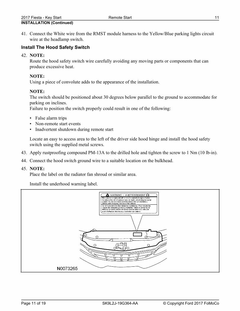
• False alarm trips• Non-RMST events• Inadvertent shutdown during RMST
Locate an easy to access area to the left of the driver side hood hinge and install the hood safetyswitch using the supplied metal screws.
Do not mount the control module in the knee bolster area.Secure the control module at three points to the vehicle.
Use the supplied long tie-straps to mount the RMST control module to the underdash wiringharness, to the right of the steering column.
Install Trim66. Install the upper and lower steering column shrouds.
Install the retainers.
67. Install the glove compartment.
68. Install the RH lower instrument panel insulator.
NOTE: The following step is for bi-directional RMST kits only.
69. Hang the customer's rear view mirror information card on the rear view mirror.
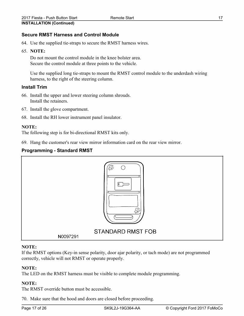
Programming - Standard RMST
NOTE: If the RMST options (Key-in sense polarity, door ajar polarity, or tach mode) are not programmedcorrectly, vehicle will not RMST or operate properly.
NOTE: The LED on the RMST harness must be visible to complete module programming.
NOTE: The RMST override button must be accessible.
70. Make sure that the hood and doors are closed before proceeding.
INSTALLATION (Continued)
Secure RMST Harness and Control Module64. Use the supplied tie-straps to secure the RMST harness wires.
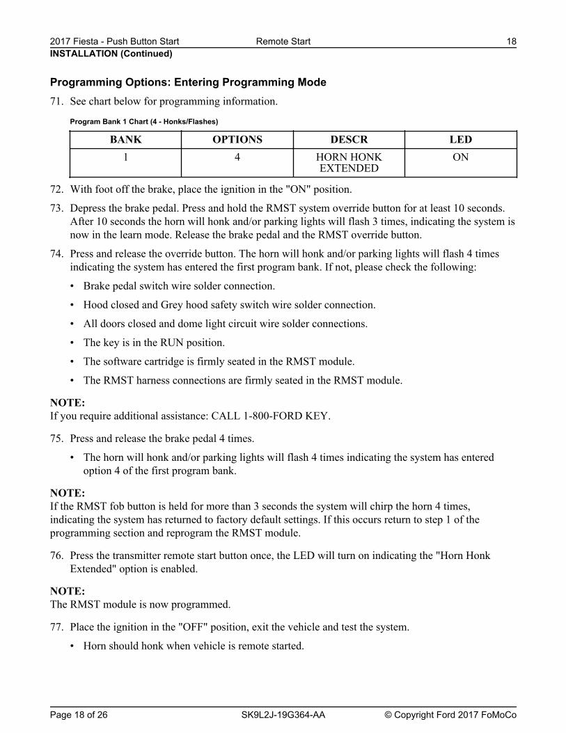
72. With foot off the brake, place the ignition in the "ON" position.
73. Depress the brake pedal. Press and hold the RMST system override button for at least 10 seconds.After 10 seconds the horn will honk and/or parking lights will flash 3 times, indicating the system isnow in the learn mode. Release the brake pedal and the RMST override button.
74. Press and release the override button. The horn will honk and/or parking lights will flash 4 timesindicating the system has entered the first program bank. If not, please check the following:
• All doors closed and dome light circuit wire solder connections.
• The key is in the RUN position.
• The software cartridge is firmly seated in the RMST module.
• The RMST harness connections are firmly seated in the RMST module.
NOTE: If you require additional assistance: CALL 1-800-FORD KEY.
75. Press and release the brake pedal 4 times.
• The horn will honk and/or parking lights will flash 4 times indicating the system has enteredoption 4 of the first program bank.
NOTE: If the RMST fob button is held for more than 3 seconds the system will chirp the horn 4 times,indicating the system has returned to factory default settings. If this occurs return to step 1 of theprogramming section and reprogram the RMST module.
76. Press the transmitter remote start button once, the LED will turn on indicating the "Horn HonkExtended" option is enabled.
NOTE: The RMST module is now programmed.
77. Place the ignition in the "OFF" position, exit the vehicle and test the system.
• Horn should honk when vehicle is remote started.
INSTALLATION (Continued)
Programming Options: Entering Programming Mode71. See chart below for programming information.
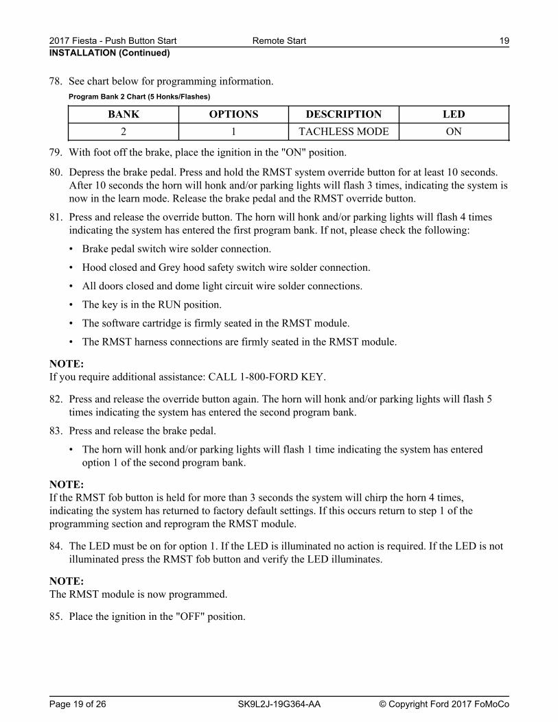
80. Depress the brake pedal. Press and hold the RMST system override button for at least 10 seconds.After 10 seconds the horn will honk and/or parking lights will flash 3 times, indicating the system isnow in the learn mode. Release the brake pedal and the RMST override button.
81. Press and release the override button. The horn will honk and/or parking lights will flash 4 timesindicating the system has entered the first program bank. If not, please check the following:
• All doors closed and dome light circuit wire solder connections.
• The key is in the RUN position.
• The software cartridge is firmly seated in the RMST module.
• The RMST harness connections are firmly seated in the RMST module.
NOTE: If you require additional assistance: CALL 1-800-FORD KEY.
82. Press and release the override button again. The horn will honk and/or parking lights will flash 5times indicating the system has entered the second program bank.
83. Press and release the brake pedal.
• The horn will honk and/or parking lights will flash 1 time indicating the system has enteredoption 1 of the second program bank.
NOTE: If the RMST fob button is held for more than 3 seconds the system will chirp the horn 4 times,indicating the system has returned to factory default settings. If this occurs return to step 1 of theprogramming section and reprogram the RMST module.
84. The LED must be on for option 1. If the LED is illuminated no action is required. If the LED is notilluminated press the RMST fob button and verify the LED illuminates.
NOTE: The RMST module is now programmed.
85. Place the ignition in the "OFF" position.
INSTALLATION (Continued)
78. See chart below for programming information.Program Bank 2 Chart (5 Honks/Flashes)
BANK OPTIONS DESCRIPTION LED2 1 TACHLESS MODE ON
79. With foot off the brake, place the ignition in the "ON" position.
88. Once security access is granted, prepare the RMST module for PATS programming. Press and holdthe brake pedal.
89. Remove the Intelligent Access key from the vehicle and place on workbench 10 feet from thevehicle.
90. Press and hold the RMST system override button on the RMST harness for at least 10 seconds.
• After 10 seconds the horn will honk 3 times, indicating the system is now in the learn mode.
• Release the brake pedal and the RMST override button.
91. Press and release the override button 1 time. The horn should honk 4 times.
92. Quickly press and release the RMST button on the RMST key fob 1 time. Verify that the LED hasturned on. This indicates that the RMST module is ready for programming to the vehicle PATSsystem.
NOTE: You may need to perform the following step TWICE in order to successfully program the RMSTsystem.
93. From the scan tool menu, select ''Program additional transponder key''. Follow the on screenprompts to program additional keys and to program the RMST system to the vehicle.
94. Disconnect the scan tool, and turn off the ignition when complete.
Functional Test - Standard RMST
NOTE: If during any of the steps of the functional test, the RMST system or vehicle doesn't react or performaccordingly, please refer to the RMST troubleshooting guide.
95. Make sure all doors are closed but hood is open and windows are down (doors will be locking).
96. Press and hold the Start button on the remote control key fob for 2-3 seconds, the Horn should honkonce indicating receipt of the start request.
97. The RMST systems should turn on the ignition, but then honk the horn twice and shut downindicating the hood is open.
INSTALLATION (Continued)
Programming the DNA-9 Using Diagnostic Equipment
NOTE: This procedure only programs the Passive Anti-Theft System (PATS) portion of the key into theInstrument Panel Cluster (IPC).
86. With an Intelligent Access key in the vehicle, turn the ignition on by pushing the Start buttonwithout depressing the brake.
87. From the scan tool, enter TOOLBOX. Select Body>Security>PATS Functions and follow theIntegrated Diagnostic System (IDS) on-screen instructions to enter PATS security access.
105.On vehicles equipped with power window interrupt, Attempt to close windows to check powerwindow interrupt function.
106.Once all systems have been checked, open the door, or press the brake pedal. The RMST systemsshould shut down.
107.Restart the vehicle then unlock and open the door. The RMST systems should shut down.
108.Verify that the vehicle can be restarted with the Intelligent Access key, 3-5 seconds after engineshutdown.
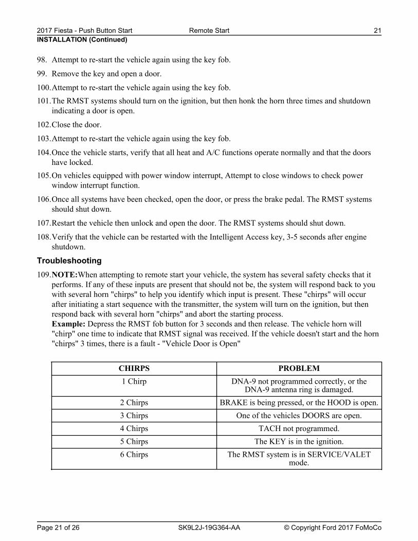
Troubleshooting109.NOTE:When attempting to remote start your vehicle, the system has several safety checks that it
performs. If any of these inputs are present that should not be, the system will respond back to youwith several horn "chirps" to help you identify which input is present. These "chirps" will occurafter initiating a start sequence with the transmitter, the system will turn on the ignition, but thenrespond back with several horn "chirps" and abort the starting process.Example: Depress the RMST fob button for 3 seconds and then release. The vehicle horn will"chirp" one time to indicate that RMST signal was received. If the vehicle doesn't start and the horn"chirps" 3 times, there is a fault - "Vehicle Door is Open"
CHIRPS PROBLEM1 Chirp DNA-9 not programmed correctly, or the
DNA-9 antenna ring is damaged.2 Chirps BRAKE is being pressed, or the HOOD is open.3 Chirps One of the vehicles DOORS are open.4 Chirps TACH not programmed.5 Chirps The KEY is in the ignition.6 Chirps The RMST system is in SERVICE/VALET
mode.
INSTALLATION (Continued)
101.The RMST systems should turn on the ignition, but then honk the horn three times and shutdownindicating a door is open.
102.Close the door.
103.Attempt to re-start the vehicle again using the key fob.
104.Once the vehicle starts, verify that all heat and A/C functions operate normally and that the doorshave locked.
98. Attempt to re-start the vehicle again using the key fob.
99. Remove the key and open a door.
100.Attempt to re-start the vehicle again using the key fob.
NOTE: If the RMST options (Key-in sense polarity, door ajar polarity, or tach mode) are not programmedcorrectly, vehicle will not RMST or operate properly.
NOTE: The LED on the RMST harness must be visible to complete module programming.
NOTE: The RMST override button must be accessible.
110.Make sure that the hood and doors are closed before proceeding.
Programming Options: Entering Programming Mode111.See chart below for programming information.
Program Bank 1 Chart (4 - Honks/Flashes)
BANK OPTIONS DESCR LED1 4 HORN HONK
EXTENDEDON
112.With foot off the brake, place the ignition in the "ON" position.
113.Depress the brake pedal. Press and hold the RMST system override button for at least 10 seconds.After 10 seconds the horn will honk and/or parking lights will flash 3 times, indicating the system isnow in the learn mode. Release the brake pedal and the RMST override button.
114.Press and release the override button. The horn will honk and/or parking lights will flash 4 timesindicating the system has entered the first program bank. If not, please check the following:
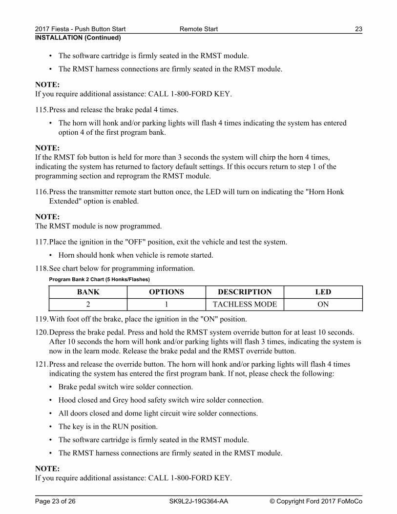
• The software cartridge is firmly seated in the RMST module.
• The RMST harness connections are firmly seated in the RMST module.
NOTE: If you require additional assistance: CALL 1-800-FORD KEY.
115.Press and release the brake pedal 4 times.
• The horn will honk and/or parking lights will flash 4 times indicating the system has enteredoption 4 of the first program bank.
NOTE: If the RMST fob button is held for more than 3 seconds the system will chirp the horn 4 times,indicating the system has returned to factory default settings. If this occurs return to step 1 of theprogramming section and reprogram the RMST module.
116.Press the transmitter remote start button once, the LED will turn on indicating the "Horn HonkExtended" option is enabled.
NOTE: The RMST module is now programmed.
117.Place the ignition in the "OFF" position, exit the vehicle and test the system.
• Horn should honk when vehicle is remote started.
118.See chart below for programming information.Program Bank 2 Chart (5 Honks/Flashes)
BANK OPTIONS DESCRIPTION LED2 1 TACHLESS MODE ON
119.With foot off the brake, place the ignition in the "ON" position.
120.Depress the brake pedal. Press and hold the RMST system override button for at least 10 seconds.After 10 seconds the horn will honk and/or parking lights will flash 3 times, indicating the system isnow in the learn mode. Release the brake pedal and the RMST override button.
121.Press and release the override button. The horn will honk and/or parking lights will flash 4 timesindicating the system has entered the first program bank. If not, please check the following:
122.Press and release the override button again. The horn will honk and/or parking lights will flash 5times indicating the system has entered the second program bank.
123.Press and release the brake pedal.
• The horn will honk and/or parking lights will flash 1 time indicating the system has enteredoption 1 of the second program bank.
NOTE: If the RMST fob button is held for more than 3 seconds the system will chirp the horn 4 times,indicating the system has returned to factory default settings. If this occurs return to step 1 of theprogramming section and reprogram the RMST module.
124.The LED must be on for option 1. If the LED is illuminated no action is required. If the LED is notilluminated press the RMST fob button and verify the LED illuminates.
NOTE: The RMST module is now programmed.
125.Place the ignition in the "OFF" position.
Programming the DNA-9 Using Diagnostic Equipment
NOTE: This procedure only programs the Passive Anti-Theft System (PATS) portion of the key into theInstrument Panel Cluster (IPC).
126.With an Intelligent Access key in the vehicle, turn the ignition on by pushing the Start buttonwithout depressing the brake.
127.From the scan tool, enter TOOLBOX. Select Body>Security>PATS Functions and follow theIntegrated Diagnostic System (IDS) on-screen instructions to enter PATS security access.
128.Once security access is granted, prepare the RMST module for PATS programming. Press and holdthe brake pedal.
129.Remove the Intelligent Access key from the vehicle and place on workbench 10 feet from thevehicle.
130.Press and hold the RMST system override button on the RMST harness for at least 10 seconds.
• After 10 seconds the horn will honk 3 times, indicating the system is now in the learn mode.
• Release the brake pedal and the RMST override button.
131.Press and release the override button 1 time. The horn should honk 4 times.
132.Quickly press and release the RMST button on the RMST key fob 1 time. Verify that the LED hasturned on. This indicates that the RMST module is ready for programming to the vehicle PATSsystem.
NOTE: You may need to perform the following step TWICE in order to successfully program the RMSTsystem.
133.From the scan tool menu, select ''Program additional transponder key''. Follow the on screenprompts to program additional keys and to program the RMST system to the vehicle.
134.Disconnect the scan tool, and turn off the ignition when complete.
Functional Test - Bi-directional RMST
NOTE: If during any of the steps of the functional test, the RMST system or vehicle doesn't react or performaccordingly, please refer to the RMST troubleshooting guide.
135.Make sure all doors are closed but hood is open and windows are down (doors will be locking).
136.Press and hold the Start button on the remote control key fob for 2-3 seconds, the Horn should honkonce indicating receipt of the start request.
137.The RMST systems should turn on the ignition, but then honk the horn twice and shut downindicating the hood is open.
138.Attempt to re-start the vehicle again using the key fob.
139.Remove the key and open a door.
140.Attempt to re-start the vehicle again using the key fob.
141.The RMST systems should turn on the ignition, but then honk the horn three times and shutdownindicating a door is open.
142.Close the door.
143.Attempt to re-start the vehicle again using the key fob.
144.Once the vehicle starts, verify that all heat and A/C functions operate normally and that the doorshave locked.
145.On vehicles equipped with power window interrupt, Attempt to close windows to check powerwindow interrupt function.
146.Once all systems have been checked, open the door, or press the brake pedal. The RMST systemsshould shut down.
147.Restart the vehicle then unlock and open the door. The RMST systems should shut down.
148.Verify that the vehicle can be restarted with the Intelligent Access key, 3-5 seconds after engineshutdown.
Troubleshooting149.NOTE: When attempting to remote start your vehicle, the system has several safety checks that it
performs. If any of these inputs are present that should not be, the system will respond back to youwith several horn "chirps" to help you identify which input is present. These "chirps" will occurafter initiating a start sequence with the transmitter, the system will turn on the ignition, but thenrespond back with several horn "chirps" and abort the starting process.Example: Depress the RMST fob button for 3 seconds and then release. The vehicle horn will"chirp" one time to indicate that RMST signal was received. If the vehicle doesn't start and the horn"chirps" 3 times, there is a fault - "Vehicle Door is Open".
CHIRPS PROBLEM1 Chirp DNA-9 not programmed correctly, or the
DNA-9 antenna ring is damaged.2 Chirps BRAKE is being pressed, or the HOOD is open.3 Chirps One of the vehicles DOORS are open.4 Chirps TACH not programmed.
7. NOTE: Do not cut the override programming button from the harness, it is used for all installations.
NOTE: For vehicle specific wiring diagram(s) click here.
Referring to the vehicle specific wiring section for the system being installed, gather all individualwires that will be routed to the same areas of the vehicle into groups. Cover each wire group withelectrical tape for approximately 18''. Depending on the vehicle, there will be 2 to 5 different wiregroups.Trim the unused wires approximately 6 - 8'' from the module.
INSTALLATION (Continued)
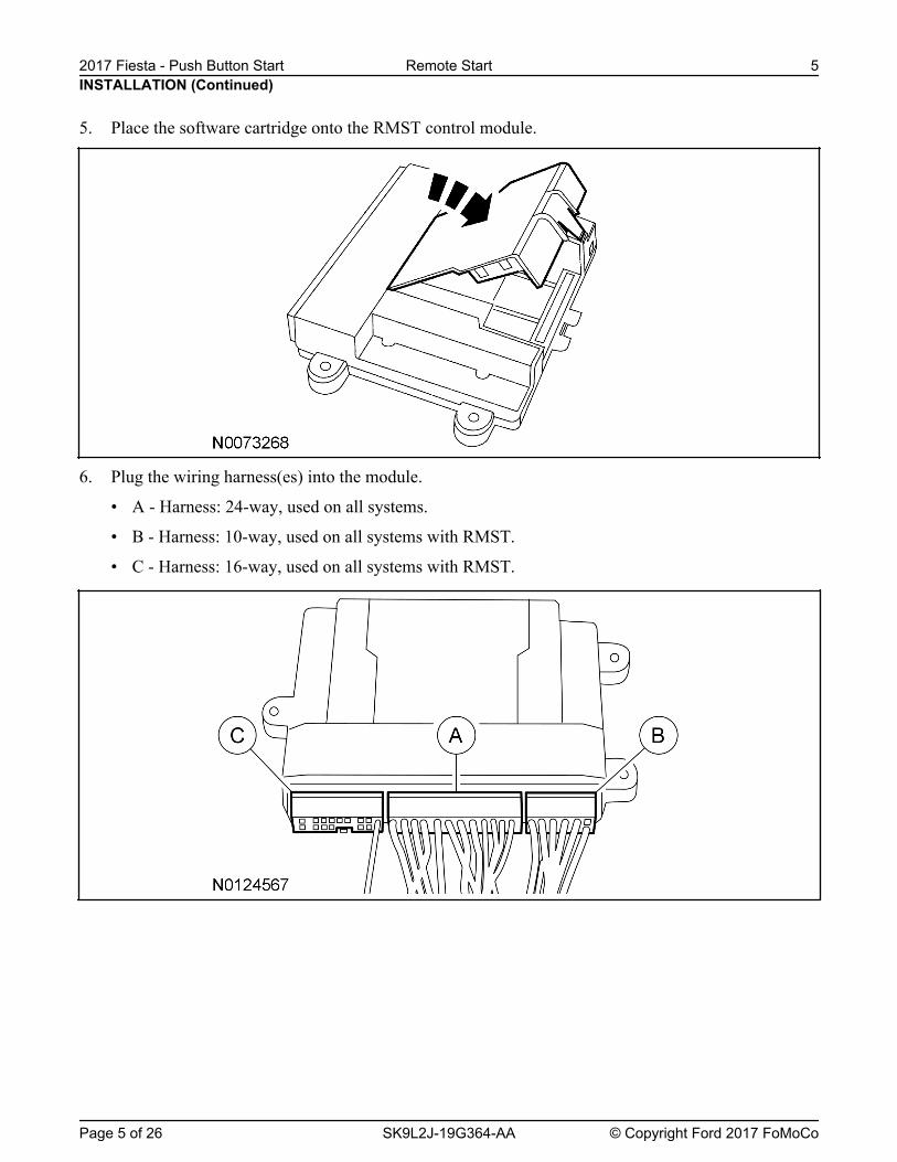
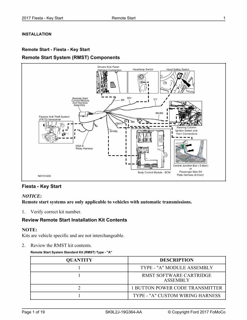
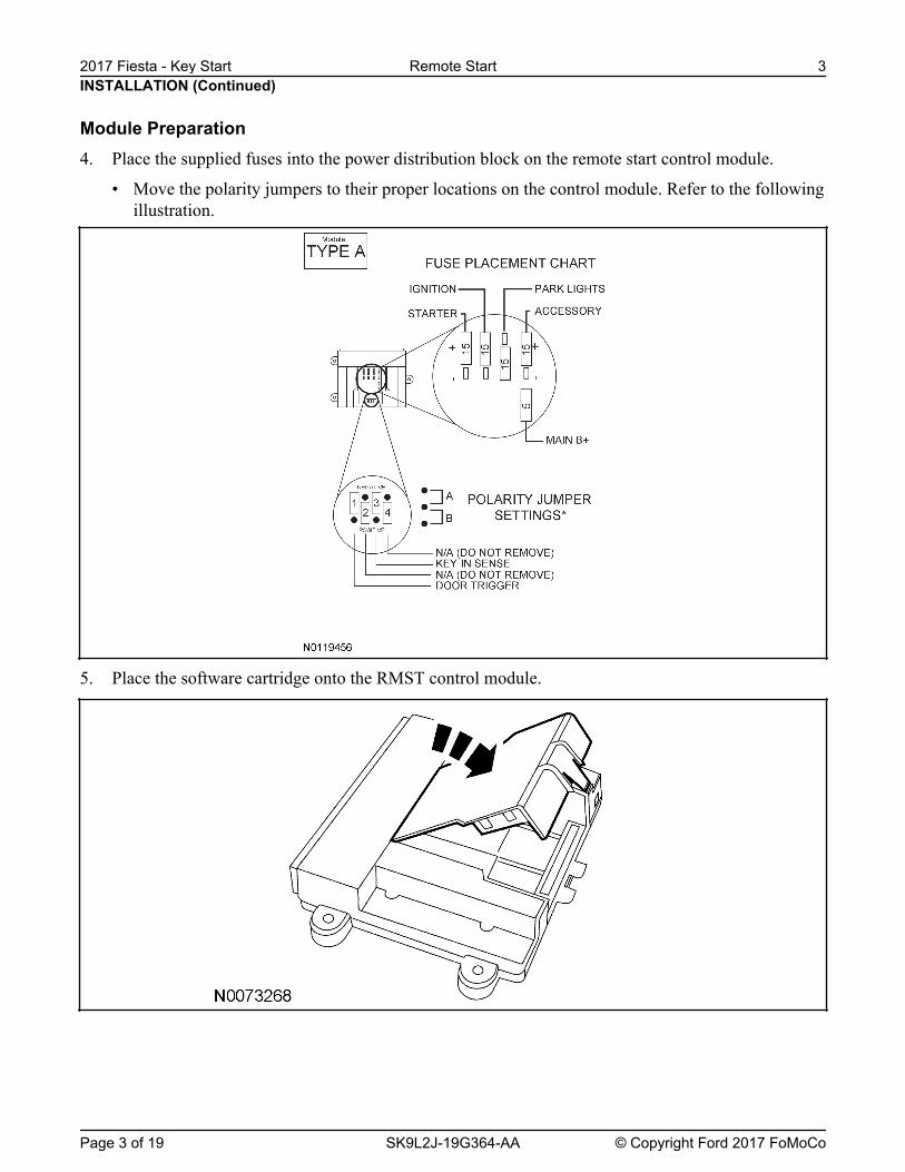
6. Plug the wiring harness(es) into the module.
• A - Harness: 24-way, used on all systems.
• B - Harness: 10-way, used on all systems with RMST.
8. Tape the harness sections together, making sure to cover all of the unused wires.
Vehicle Preparation9. Remove the retainers and the upper and lower steering column shrouds.
10. Open and remove the glove box.
11. Remove the RH lower Instrument panel insulator.
12. Using a suitable non-marring tool, work around the outer edge of the headlamp switch to release theclips and pull the switch out through the front of the finish panel.
13. Install the supplied wire harness label to the headlamp switch harness.
• If required, fish the headlamp switch wire harness out of the instrument panel.
14. Connect and install the headlamp switch.
Antenna Mounting
NOTE: For good range of operation, the antenna must be installed correctly.
NOTE: Keep these points in mind when selecting a location and mounting the antenna.
• Do not mount the antenna behind or on any metal film or window tinting on the windshield.• Do not mount the antenna so that one of the antenna elements touches or crosses any vehicle wiring
and/or metal.• Do not mount the antenna close to RF devices, (EZ Pass, etc), that are installed on the windshield.• On vehicles without metal film in the windshield around the rear view mirror, mount the antenna
between the headliner and the rear view mirror.• On vehicles equipped with an electronic mirror, or on vehicles with metal film around the rearview
mirror, mount the antenna approximately 3 inches below the mirror attachment point to thewindshield and/or mirror electronics.
15. Choose a suitable mounting location based on the guidelines above.
Install The Antenna16. Clean the mounting surface using an alcohol base solution and a clean cloth.
17. NOTE: Do not touch the adhesive, reduced adhesion may result.
NOTE: Make sure that the long wire on the antenna is pointing towards the top of the windshield since thiswire will be routed along the headliner.
NOTE: It is recommended to identify all vehicle wires that will be connected before making any permanentconnections. If all wires cannot be located, call 1-800-FORDKEY.
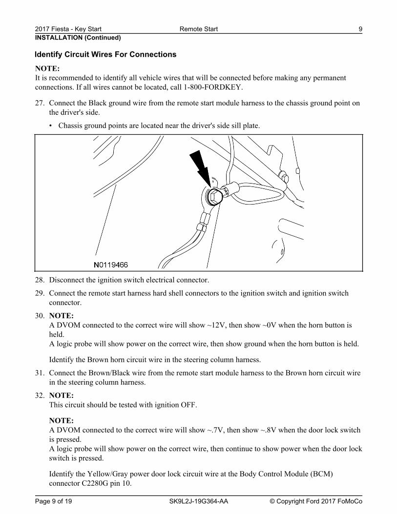
27. Connect the Black ground wire from the remote start module harness to the chassis ground point onthe driver's side.
• Chassis ground points are located near the driver's side sill plate.
28. Disconnect the ignition switch electrical connector.
29. Connect the remote start harness hard shell connectors to the ignition switch and ignition switchconnector.
30. NOTE: A DVOM connected to the correct wire will show ~12V, then show ~0V when the horn button isheld.A logic probe will show power on the correct wire, then show ground when the horn button is held.
Identify the Brown horn circuit wire in the steering column harness.
31. Connect the Brown/Black wire from the remote start module harness to the Brown horn circuit wirein the steering column harness.
32. NOTE: This circuit should be tested with ignition OFF.
NOTE: A DVOM connected to the correct wire will show ~.7V, then show ~.8V when the door lock switchis pressed.A logic probe will show power on the correct wire, then continue to show power when the door lockswitch is pressed.
Identify the Yellow/Gray power door lock circuit wire at the Body Control Module (BCM)connector C2280G pin 10.
33. Connect the Blue wire from the remote start module harness to the Yellow/Gray power door lock circuit wire at the BCM connector C2280G pin 10.
34. NOTE:A DVOM connected to the correct wire will show ~0V, then show ~12V while depressing the brake pedal.A logic probe will show ground on the correct wire, then show power while depressing the brake pedal.
Identify the Blue/Gray brake switch circuit wire at the BCM connector C2280B pin 12.
35. Connect the Brown wire from the remote start module harness to the Blue/Gray brake switch circuit wire at the BCM connector C2280B pin 12.
36. NOTE:A DVOM connected to the correct wire will show ~0V with the vehicle door(s) open and the dome light ON, then show ~12V with the vehicle door(s) closed and the dome light OFF.
NOTE:A logic probe connected to the correct wire will show ground with the vehicle door(s) open and the dome light ON, then show power with the vehicle door(s) closed and the dome light OFF.
NOTE:Be sure that the dome light has timed out and is OFF before performing the door closed test.Be sure that the dome lamp is illuminated before performing the door open test.
Identify the Yellow/Gray dome light circuit wire at the BCM connector C2280C pin 5.
37. Connect the Green/Violet wire from the remote start module harness to the Yellow/Gray dome light circuit wire at the BCM connector C2280C pin 5.
38. NOTE:A DVOM connected to the correct wire will show ~1V, when doors are unlocked (lock LED OFF), then show power when doors are locked (lock LED ON).A logic probe will show open on the correct wire when doors are unlocked (lock LED OFF), then show power when doors are locked (lock LED ON).
Identify the Green/Violet door lock circuit wire at the BCM connector C2280E pin 12.
39. Connect the White/Blue wire from the remote start module harness to the Green/Violet door lock circuit wire at the BCM connector C2280E pin 12.
40. NOTE:A DVOM connected to the correct wire will show ~.7V with the parking light switch OFF, then show ground with the parking light switch ON.
NOTE:A Logic probe will show power with the parking light switch OFF and ground with the parking light switch ON.
Identify the Yellow/Blue parking lights circuit wire at the headlamp switch.
41. Connect the White wire from the RMST module harness to the Yellow/Blue parking lights circuitwire at the headlamp switch.
Install The Hood Safety Switch42. NOTE:
Route the hood safety switch wire carefully avoiding any moving parts or components that canproduce excessive heat.
NOTE: Using a piece of convolute adds to the appearance of the installation.
NOTE: The switch should be positioned about 30 degrees below parallel to the ground to accommodate forparking on inclines.Failure to position the switch properly could result in one of the following:
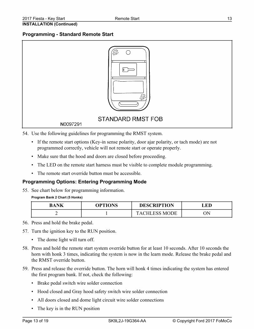
54. Use the following guidelines for programming the RMST system.
• If the remote start options (Key-in sense polarity, door ajar polarity, or tach mode) are notprogrammed correctly, vehicle will not remote start or operate properly.
• Make sure that the hood and doors are closed before proceeding.
• The LED on the remote start harness must be visible to complete module programming.
• The remote start override button must be accessible.
Programming Options: Entering Programming Mode55. See chart below for programming information.
Program Bank 2 Chart (5 Honks)
BANK OPTIONS DESCRIPTION LED2 1 TACHLESS MODE ON
56. Press and hold the brake pedal.
57. Turn the ignition key to the RUN position.
• The dome light will turn off.
58. Press and hold the remote start system override button for at least 10 seconds. After 10 seconds thehorn with honk 3 times, indicating the system is now in the learn mode. Release the brake pedal andthe RMST override button.
59. Press and release the override button. The horn will honk 4 times indicating the system has enteredthe first program bank. If not, check the following:
• The software cartridge is firmly seated in the RMST module
• The RMST harness connections are firmly seated in the RMST module
NOTE: If you require additional assistance, CALL 1-800-FORD KEY.
60. Press and release the override button again. The horn will honk 5 times indicating the system hasentered the second program bank.
61. Press and release the brake pedal.
• The horn will honk 1 time indicating the system has entered option 1 of the second programbank.
NOTICE: When turning LED on or off using remote start fob button, quickly press and immediately releasethe remote start button. Failure to quickly release the remote start fob button will result in systemdefaulting to the factory options.
62. The LED must be on for option 1. If the LED is illuminated, no action is required. If the LED is notilluminated press the remote start fob button and verify the LED illuminates.
NOTE: If the remote start fob button is held for more than 3 seconds, the system will chirp the horn 4 times,indicating the system has returned to factory default settings. If this occurs, return to step 1 of theprogramming section and reprogram the remote start module.
NOTE: The remote start module is now programmed.
63. Remove the ignition key.
Programming the DNA-9
NOTE: DNA-9 module programming must be completed with the driver door open.
NOTE: Two PATS keys are required to program the DNA-9.
NOTE: IMPORTANT: Each of the following steps should be completed with no more than a 5 second delaybetween steps.
64. With all doors closed, insert the first ignition key and turn to the RUN position.
• Leave key on for 5 seconds, turn off and remove.
65. Insert the second ignition key and turn to the RUN position.
• Leave key on for 5 seconds, turn off and remove.
66. Press and hold the remote start button for 3 seconds.
• Verify the vehicle is started and remains running until the brake pedal is pressed or the door isopened.
NOTE: If the vehicle fails to start, repeat steps 1-3 and reprogram.
NOTE: The engine will start if the Remote Start kit has been installed correctly, the brake is not depressed, andthe hood is closed.
Functional Test - Standard Remote Start
NOTE: If during any of the steps of the functional test, the remote start system or vehicle doesn't react orperform accordingly, please refer to the remote start troubleshooting guide.
NOTE: For remote start troubleshooting guide click here.
67. Make sure all doors are closed but hood is open and windows are down (doors will be locking).
68. Press and hold the Start button on the remote control key fob for 2-3 seconds - horn should honkonce indicating receipt of the start request.
69. The remote start systems should turn on the ignition, but then honk the horn twice and shut downindicating the hood is open.
70. Close the hood and insert a key into the ignition switch.
71. Attempt to re-start the vehicle again using the key fob.
72. The remote start systems should turn on the ignition, but then honk the horn five times and shutdown indicating a key is in the ignition switch.
73. Remove the key and open a door.
74. Attempt to re-start the vehicle again using the key fob.
75. The remote start systems should turn on the ignition, but then honk the horn three times and shutdown indicating a door is open.
76. Close the door.
77. Attempt to re-start the vehicle again using the key fob..
78. Once the vehicle starts, verify that all heat and A/C functions operate normally and that the doorshave locked.
79. On vehicles equipped with power window interrupt, attempt to close the windows to check powerwindow interrupt function.
80. Once all systems have been checked, open the door*, or press the brake pedal - the remote startsystems should shut down.
*MyKey vehicle remote start systems will shut down upon vehicle entry. Please see vehicle owner'sguide or remote start owner's manual for more information.
Troubleshooting81. NOTE:
When attempting to remote start the vehicle, the system has several safety checks that it performs. Ifany of these inputs are present that should not be, the system will respond back with several horn"chirps" to help identify which input is present. These "chirps" will occur after initiating a startsequence with the transmitter. The system will turn on the ignition, but then respond back withseveral horn "chirps" and abort the starting process.
Example: Depress the remote start fob button for 3 seconds and then release. The vehicle horn will "chirp" one time to indicate that RMST signal was received. If the vehicle does not start and the horn "chirps" 3 times, there is a fault - "Vehicle Door is Open".
CHIRPS PROBLEM1 Chirp DNA-9 not programmed correctly, or the
DNA-9 harness is damaged.2 Chirps BRAKE is being pressed, or the HOOD is open.3 Chirps One of the vehicle DOORS is open.4 Chirps TACH not programmed.
5 Chirps The KEY is in the ignition.6 Chirps The remote start system is in SERVICE/VALET
mode.
Programming Bi-directional Remote Start
82. Use the following guidelines for programming the RMST system.
• If the remote start options (Key-in sense polarity, door ajar polarity, or tach mode) are notprogrammed correctly, vehicle will not remote start or operate properly.
• Make sure that the hood and doors are closed before proceeding.
• The LED on the remote start harness must be visible to complete module programming.
• The remote start override button must be accessible.
Programming Options: Entering Programming Mode83. See chart below for programming information.
Program Bank 2 Chart (5 Honks)
BANK OPTIONS DESCRIPTION LED2 1 TACHLESS MODE ON
84. Press and hold the brake pedal.
85. Turn the ignition key to the RUN position.The dome light will turn off.
86. Press and hold the remote start system override button for at least 10 seconds.After 10 seconds the horn will honk 3 times, indicating the system is now in the learn mode.Release the brake pedal and the RMST override button.
87. Press and release the override button. The horn will honk 4 times indicating the system has enteredthe first program bank.If not, check the following:
• All doors closed and dome light circuit wire solder connections
• The key is in the RUN position
• The software cartridge is firmly seated in the RMST module
• The RMST harness connections are firmly seated in the RMST module
NOTE: If you require additional assistance, CALL 1-800-FORD KEY.
88. Press and release the override button again. The horn will honk 5 times indicating the system hasentered the second program bank.
89. Press and release the brake pedal.The horn will honk 1 time indicating the system has entered option 1 of the second program bank.
NOTICE: When turning LED on or off using remote start fob button, quickly press and immediately releasethe remote start button. Failure to quickly release the remote start fob button will result in systemdefaulting to the factory options.
90. The LED must be on for option 1. If the LED is illuminated, no action is required. If the LED is notilluminated, press the remote start fob button and verify the LED illuminates.
NOTE: If the remote start fob button is held for more than 3 seconds, the system will chirp the horn 4 times,indicating the system has returned to factory default settings. If this occurs, return to step 1 of theprogramming section and reprogram the remote start module.
NOTE: Two PATS keys are required to program the DNA-9.
NOTE: IMPORTANT: Each of the following steps should be completed with no more than a 5 second delaybetween steps.
92. Insert the first ignition key and turn to the RUN position.
• Leave key on for 5 seconds then turn off and remove key.
93. Insert the second ignition key and turn to the RUN position.
• Leave key on for 5 seconds then turn off and remove key.
NOTE: If the PATS light blinks rapidly, repeat steps 1-3 to retry programming the DNA-9.
NOTE: The engine will start if the Remote Start kit has been installed correctly, the brake is not depressed, andthe hood and doors are closed.
94. Press the remote start button key icon twice within 3 seconds.The PATS light should stay on for 3-5 seconds before turning off, which means that the DNA-9 wassuccessfully programmed.
Functional Test - Bi-directional Remote Start
NOTE: If during any of the steps of the functional test the remote start system or vehicle doesn't react orperform accordingly, please refer to the remote start troubleshooting guide.
NOTE: For remote start troubleshooting guide click here.
95. Make sure all doors are closed but hood is open and windows are down (doors will be locking).
96. Press the Start button on the remote control key fob twice within 3 seconds - horn should honk onceindicating receipt of the start request.
97. The remote start systems should turn on the ignition, but then honk the horn twice and shut downindicating the hood is open.
98. Close the hood and insert a key into the ignition switch.
99. Attempt to re-start the vehicle again using the key fob.
100.The remote start systems should turn on the ignition, but then honk the horn five times and shutdown indicating a key is in the ignition switch.
102.Attempt to re-start the vehicle again using the key fob.
103.The remote start systems should turn on the ignition, but then honk the horn three times and shutdown indicating a door is open.
104.Close the door.
105.Attempt to re-start the vehicle again using the key fob..
106.Once the vehicle starts, verify that all heat and A/C functions operate normally and that the doorshave locked.
107.On vehicles equipped with power window interrupt, attempt to close the windows to check powerwindow interrupt function.
108.Once all systems have been checked, open the door*, or press the brake pedal - the remote startsystems should shut down.
NOTE: *MyKey vehicle remote start systems will shut down upon vehicle entry. Please see vehicle owner'sguide or remote start owner's manual for more Information.
Troubleshooting109.NOTE:
When attempting to remote start the vehicle, the system has several safety checks that it performs. Ifany of these inputs are present that should not be, the system will respond back with several horn"chirps" to help identify which input is present. These "chirps" will occur after initiating a startsequence with the transmitter. The system will turn on the ignition, but then respond back withseveral horn "chirps" and abort the starting process.
Example: Depress the remote start fob button for 3 seconds and then release. The vehicle horn will"chirp" one time to indicate that RMST signal was received. If the vehicle does not start and thehorn "chirps" 3 times, there is a fault - "Vehicle Door is Open"
CHIRPS PROBLEM1 Chirp DNA-9 not programmed correctly, or the
DNA-9 harness is damaged.2 Chirps BRAKE is being pressed, or the HOOD is open.3 Chirps One of the vehicle DOORS is open.4 Chirps TACH not programmed.
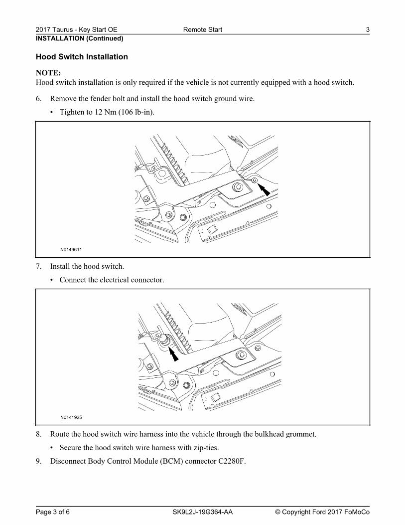
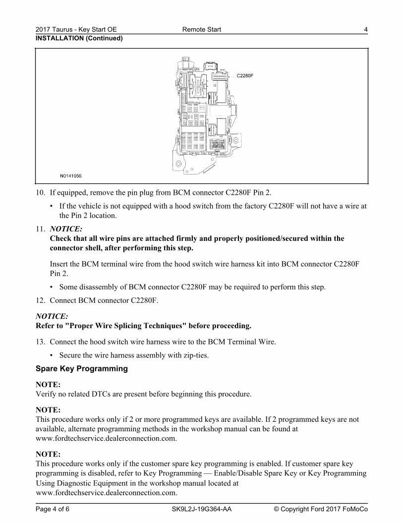
10. If equipped, remove the pin plug from BCM connector C2280F Pin 2.
• If the vehicle is not equipped with a hood switch from the factory C2280F will not have a wire atthe Pin 2 location.
11. NOTICE: Check that all wire pins are attached firmly and properly positioned/secured within theconnector shell, after performing this step.
Insert the BCM terminal wire from the hood switch wire harness kit into BCM connector C2280FPin 2.
• Some disassembly of BCM connector C2280F may be required to perform this step.
12. Connect BCM connector C2280F.
NOTICE: Refer to "Proper Wire Splicing Techniques" before proceeding.
13. Connect the hood switch wire harness wire to the BCM Terminal Wire.
• Secure the wire harness assembly with zip-ties.
Spare Key Programming
NOTE: Verify no related DTCs are present before beginning this procedure.
NOTE: This procedure works only if 2 or more programmed keys are available. If 2 programmed keys are notavailable, alternate programming methods in the workshop manual can be found atwww.fordtechservice.dealerconnection.com.
NOTE: This procedure works only if the customer spare key programming is enabled. If customer spare keyprogramming is disabled, refer to Key Programming — Enable/Disable Spare Key or Key Programming
INSTALLATION (Continued)
Using Diagnostic Equipment in the workshop manual located atwww.fordtechservice.dealerconnection.com.
14. Cut the keys that are going to be programmed to match the existing keys.
15. Insert the first programmed Passive Anti-Theft System (PATS) key into the ignition and turn thekey from the OFF position to the RUN position (maintain the key in the RUN position forapproximately 3 seconds).
16. Turn the first key to the OFF position and remove the key from the ignition.
17. Within 10 seconds of turning the key to the OFF position, insert a second programmed PATS keyinto the ignition and turn the key from the OFF position to the RUN position (maintain the key inthe RUN position for approximately 3 seconds).
18. Turn the second key to the OFF position and remove the key from the ignition.
19. NOTE: The doors lock and then unlock to confirm that each Integrated Key Transmitter (IKT) isprogrammed.
Within 10 seconds of turning the second key to the OFF position, insert the new, unprogrammedPATS key into the ignition and turn the key from the OFF position to the RUN position (maintainthe key in the RUN position for approximately 3 seconds).
20. If it is desired to program additional key(s) (up to a total of 4 keys can be programmed), repeat theSpare Key Programming procedure for each additional key.
Remote Start Activation21. Verify that the IDS is updated to the most current version.
22. Connect IDS.
• Follow the prompts to select new vehicle session.
• Confirm VIN.
23. Activate the remote start using the IDS.
• Select the Tool Box icon.
• Select Body.
• Select Security.
• Select Remote Start.
• Verify that the information on the IDS screen is correct and all procedures have been followed.
• Select Yes. This will enable the remote start function on the vehicle.
24. For vehicles equipped with standard message center, verify that the remote start option nowappears.
• Using the Select and Arrow buttons on the steering wheel, select Settings.