31
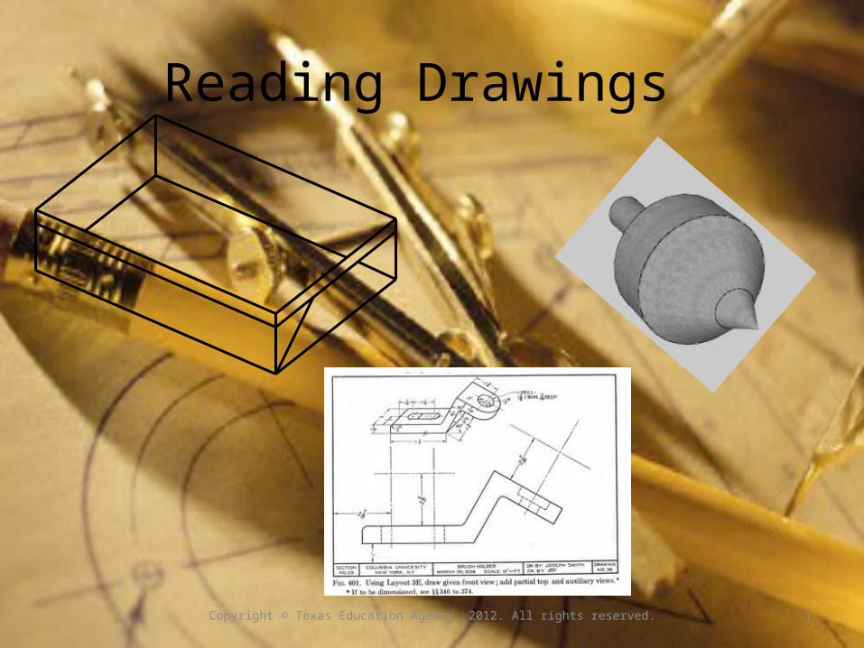
Reading Drawings Copyright © Texas Education Agency, 2012. All rights reserved. 1
| Date post: | 19-Dec-2015 |
| Category: |
Documents |
| Upload: | madison-parsons |
| View: | 213 times |
| Download: | 0 times |
Reading Drawings
Copyright © Texas Education Agency, 2012. All rights reserved.
1
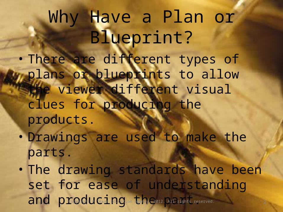
Why Have a Plan or Blueprint?
• There are different types of plans or blueprints to allow the viewer different visual clues for producing the products.
• Drawings are used to make the parts.• The drawing standards have been set for ease
of understanding and producing the part.• There are different types of lines used to draw
a blueprint or a plan.
Copyright © Texas Education Agency, 2012. All rights reserved.
2
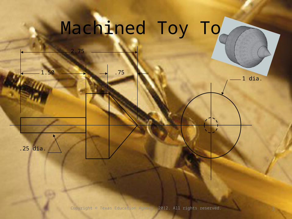
Machined Toy Top
1 dia.
2.75
1.50 .75
.25 dia.
Copyright © Texas Education Agency, 2012. All rights reserved.
3

Types of Drawings
Copyright © Texas Education Agency, 2012. All rights reserved.
4

Three View Drawing or Working Drawing
The three view drawing or working drawing shows the object from three sides. These views will show the shape of the object and location of any cutouts or holes.The dimensions are usually added to this type of plan.
1
1 1/2
3
2 1/2
1 3/4
Copyright © Texas Education Agency, 2012. All rights reserved.
5

Oblique Drawing
The oblique drawing is a pictorial drawing showing the shape of the object.The drawing is drawn as a front view, then the depth is projected from the corners at an
angle.There are no dimensions or hidden lines on an oblique drawing.
Copyright © Texas Education Agency, 2012. All rights reserved.
6
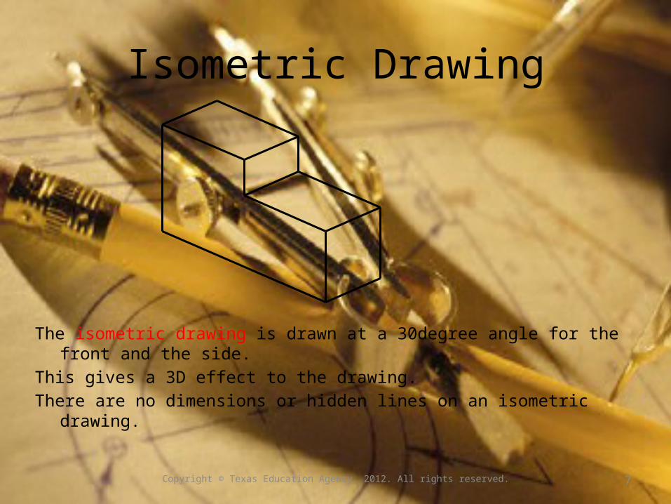
Isometric Drawing
The isometric drawing is drawn at a 30degree angle for the front and the side.This gives a 3D effect to the drawing.There are no dimensions or hidden lines on an isometric drawing.
Copyright © Texas Education Agency, 2012. All rights reserved.
7

Exploded View Drawing
This drawing shows how parts in an assembly fit together.
Copyright © Texas Education Agency, 2012. All rights reserved.
8

Sectional View Drawing
The sectional view is a drawing with a part removed or cut out to show the internal parts of the part.
Copyright © Texas Education Agency, 2012. All rights reserved.
9
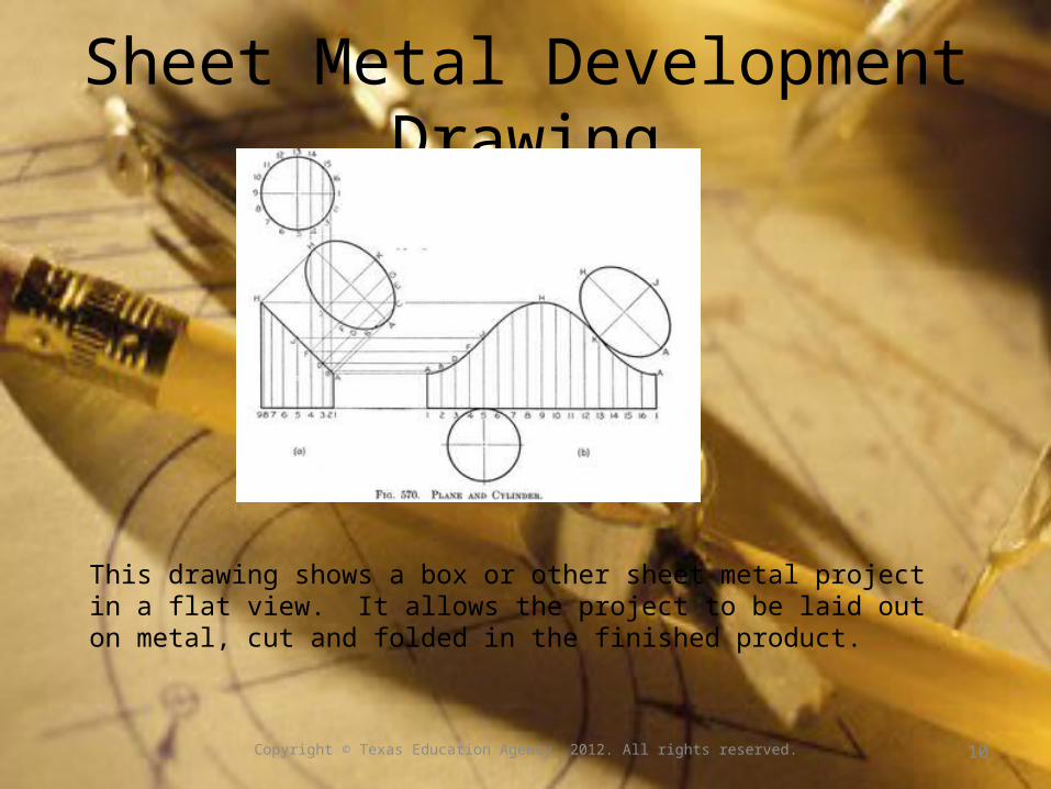
Sheet Metal Development Drawing
This drawing shows a box or other sheet metal project in a flat view. It allows the project to be laid out on metal, cut and folded in the finished product.
Copyright © Texas Education Agency, 2012. All rights reserved.
10

Welding Plans
.
The welding drawings describe how the weld joints are to be produced.
Copyright © Texas Education Agency, 2012. All rights reserved.
11
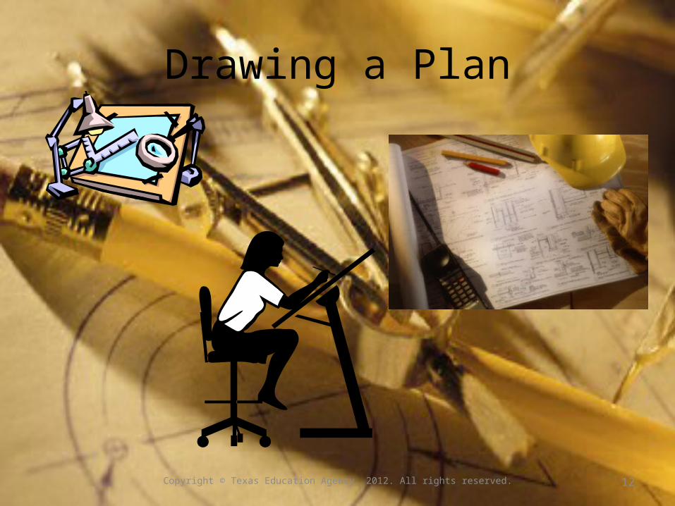
Drawing a Plan
Copyright © Texas Education Agency, 2012. All rights reserved.
12

Drawing a Plan
• Only necessary views are drawn.• They show shape, location and size.• The front view shows the most detail.• Dimensions are in between views if possible.• Other views may be added for clarification.
Copyright © Texas Education Agency, 2012. All rights reserved.
13

Drawing Projection
Copyright © Texas Education Agency, 2012. All rights reserved.
14
Fig. 256 Revolution of the Planes of Projections.Fig. 257 All Planes Are Revolved until they Coincide with the Front Plane
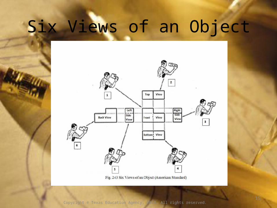
Six Views of an Object
Copyright © Texas Education Agency, 2012. All rights reserved. 15

Necessary Views of a Drawing
The three views in black are the necessary views: front, top, and right side.The three views in red are mirror images of the black views and show the details as hidden lines.
Copyright © Texas Education Agency, 2012. All rights reserved.
16

Dimensions on a Drawing
3
2
1 ½
1
1
1 ½
1
1
1
2
1
1 ½ 1 ½
3
Dimensioning each view makes the drawing too difficult to understand. The dimensions are placed on the drawing only once.
Copyright © Texas Education Agency, 2012. All rights reserved.
17
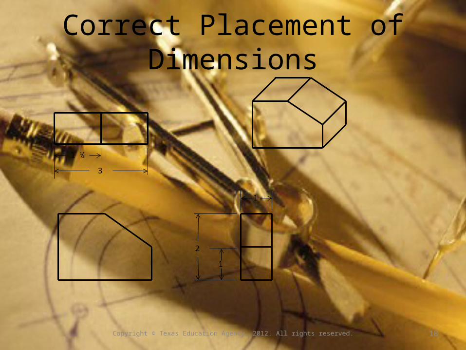
Correct Placement of Dimensions
1
1
2
1 ½
3
Copyright © Texas Education Agency, 2012. All rights reserved.
18

Types of Lines on a Blueprint
What do dashed
lines mean? What are all the
arrows pointing to?
Copyright © Texas Education Agency, 2012. All rights reserved.
19

Line Symbol Definition
Object Solid black line showing the shape of an object
Hidden Dashed line as dark as the object line shows shapes covered by other parts. For example, depth of a hole, etc.
Center Line with a dash in the middle or a plus with lines radiating from it shows where the center is located.
Section Line that has long and short sections with arrows pointed out shows the inside of a part by cutting out a section.
Fold Line with 2 X’s show where to fold a sheet metal development.
Extension A thin line extending from the edge to the dimension line indicates the dimension.
Dimension Thin lines pointing to the extension lines show the measurement.
+
X X
2
Copyright © Texas Education Agency, 2012. All rights reserved.
20
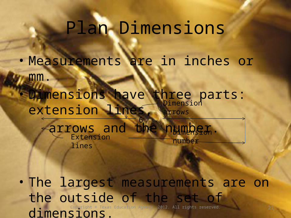
Plan Dimensions
• Measurements are in inches or mm.• Dimensions have three parts: extension lines, arrows and the number.
• The largest measurements are on the outside of the set of dimensions.
6 1/4
Extension linesDimension number
Dimension arrows
Copyright © Texas Education Agency, 2012. All rights reserved.
21

Examples of Plans
Copyright © Texas Education Agency, 2012. All rights reserved.
22
Fig. 304. Draw views with instruments; add missing lines. Layout 3D (Appendix I).

Worm Saddle Plans
2 1/2 2 1/2
2 7/8
7 1/2
1 1/2
3/4
1/4
3
2 Dia.
7/8 2 7/8
½ DRILL 2 HOLES
7/8 DRILL
3
WORM SADDLE
Copyright © Texas Education Agency, 2012. All rights reserved.
23
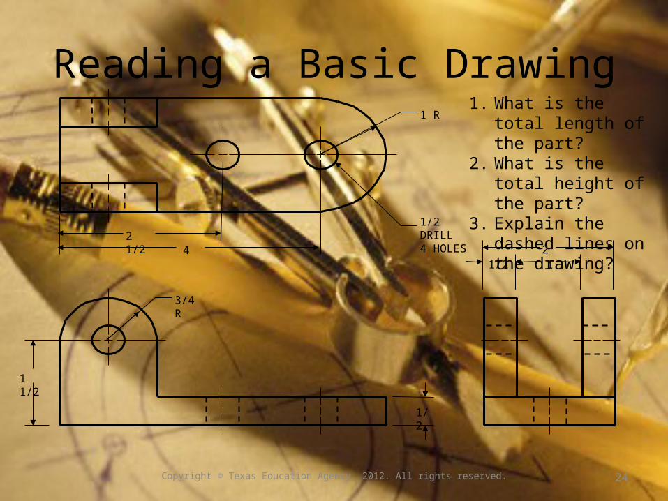
Reading a Basic Drawing
1 1/2
1/2
2 1/24
1/2 DRILL4 HOLES
1 R
3/4 R
1/2 12
1. What is the total length of the part?
2. What is the total height of the part?
3. Explain the dashed lines on the drawing?
Copyright © Texas Education Agency, 2012. All rights reserved.
24
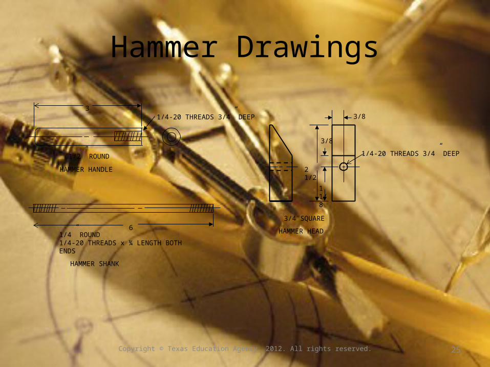
Hammer Drawings
1/2” ROUND
31/4-20 THREADS 3/4” DEEP
HAMMER HANDLE
61/4” ROUND 1/4-20 THREADS x ¾ LENGTH BOTH ENDS
HAMMER SHANK
3/4 SQUARE
2 1/2
1 1/8
3/8
3/8
1/4-20 THREADS 3/4” DEEP
HAMMER HEAD
Copyright © Texas Education Agency, 2012. All rights reserved.
25
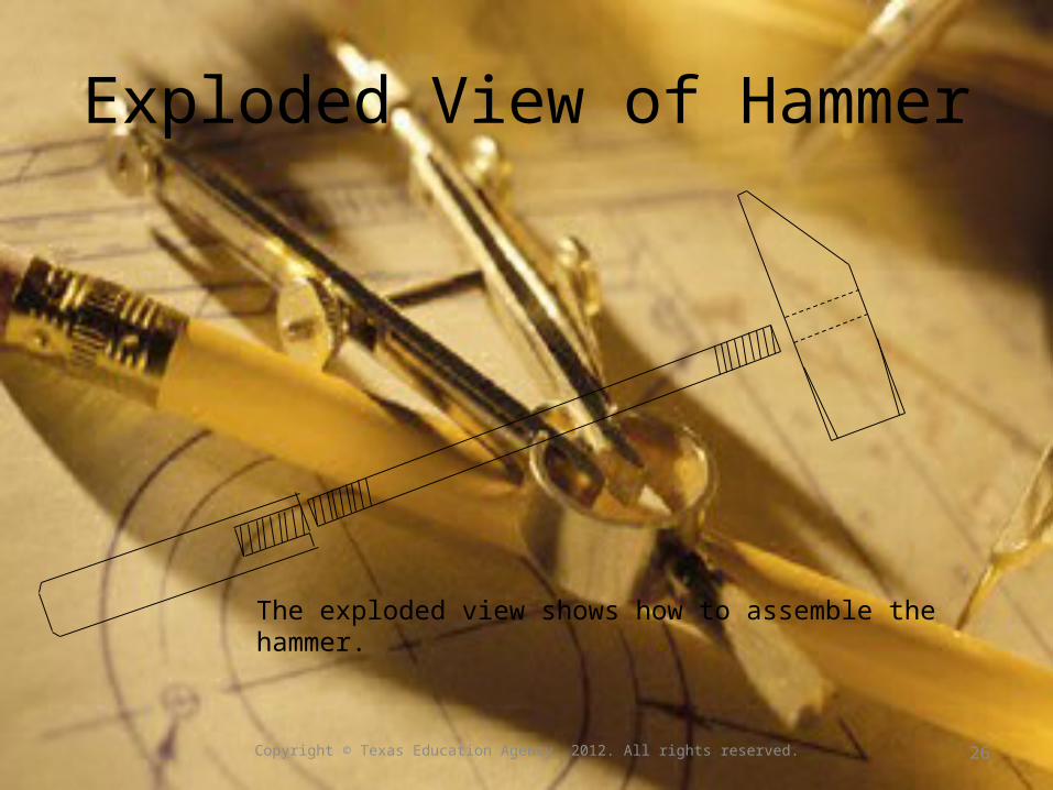
Exploded View of Hammer
The exploded view shows how to assemble the hammer.
Copyright © Texas Education Agency, 2012. All rights reserved.
26
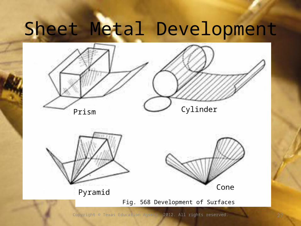
Sheet Metal Development
Prism Cylinder
PyramidCone
Copyright © Texas Education Agency, 2012. All rights reserved.
Fig. 568 Development of Surfaces
27
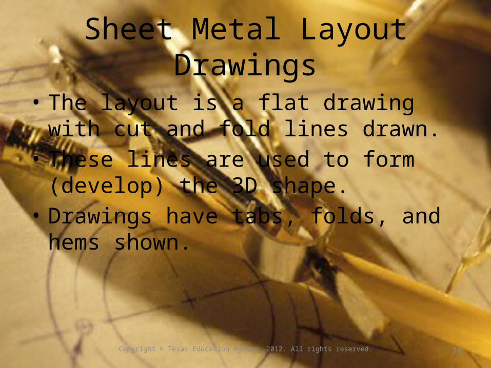
Sheet Metal Layout Drawings
• The layout is a flat drawing with cut and fold lines drawn.
• These lines are used to form (develop) the 3D shape.
• Drawings have tabs, folds, and hems shown.
Copyright © Texas Education Agency, 2012. All rights reserved.
28

Sheet Metal Box Plans
8 1/2 5
1/4 Hems All Around
11
8 1/2
1
1
45°
XXX
XXX
XX
X
XX
X
X
X
X
X
X X
XX
Hem
Fold
Hems fold over the edges so it is not sharp and the edge is strengthened.Folds are marked to allow for bending the shape.
Copyright © Texas Education Agency, 2012. All rights reserved.
29
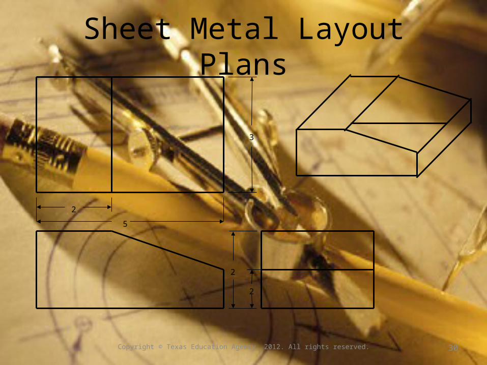
Sheet Metal Layout Plans
2
3
2
2
5
Copyright © Texas Education Agency, 2012. All rights reserved.
30
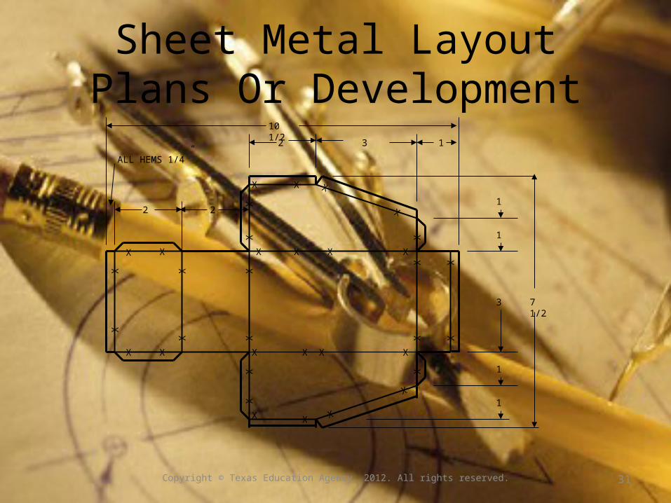
Sheet Metal Layout Plans Or Development
10 1/2
2 2
2
1
1
ALL HEMS 1/4”
13
1
1
3 7 1/2
X
XXX
XX
XXX
XX
XX
XX
X
XX X
X
XX
XXX
X
XX
XXX
X
X
X
X
X
Copyright © Texas Education Agency, 2012. All rights reserved.
31


