Real-time Dense Surface Reconstruction for Aerial Manipulation Marco Karrer * , Mina Kamel ** , Roland Siegwart ** and Margarita Chli * * Vision for Robotics Lab and ** Autonomous Systems Lab, ETH Zurich, Switzerland Abstract— With robotic systems reaching considerable ma- turity in basic self-localization and environment mapping, new research avenues open up pushing for interaction of a robot with its surroundings for added autonomy. However, the transition from traditionally sparse feature-based maps to dense and accurate scene-estimation imperative for realistic manipulation is not straightforward. Moreover, achieving this level of scene perception in real-time from a computationally constrained and highly shaky and agile platform, such as a small an Unmanned Aerial Vehicle (UAV) is perhaps the most challenging scenario for perception for manipulation. Drawing inspiration from otherwise computationally constraining Computer Vision tech- niques, we present a system combining visual, inertial and depth information to achieve dense, local scene reconstruction of high precision in real-time. Our evaluation testbed is formed using ground-truth not only in the pose of the sensor-suite, but also the scene reconstruction using a highly accurate laser scanner, offering unprecedented comparisons of scene estimation to ground-truth using real sensor data. Given the lack of any real, ground-truth datasets for environment reconstruction, our V4RL Dense Surface Reconstruction dataset is publicly available 1 . I. INTRODUCTION For a robot to be able to interact with its environment, awareness of both its ego-motion as well as its workspace are necessary. With Simultaneous Localization And Mapping (SLAM) techniques opening up new horizons in robotic autonomy, we have witnessed a series of impressive break- throughs to motion and environment estimation all the way from systems using range sensors on ground robots [1], [2] to real-time SLAM from a single camera [3]. It is due to this progress that vision-based flights with all processing and sensing onboard a small Unmanned Aerial Vehicle (UAV) were made possible [4]. Combining visual and inertial cues is now accepted as a powerful setup suitable for UAV naviga- tion offering complementary sensor information at relatively low weight, power and computation resources, which are particularly limited onboard UAVs. Aiming for more robust and scalable solutions, Visual-Inertial (VI) SLAM has come a long way with systems such as [5] and [6] able to perform with unprecedented robustness, albeit still prone to drift and erroneous estimates due to common challenges, such as lighting changes and fast camera motion. With the increasing availability and affordability of UAVs as well as the acquired knowledge on the controls, active interaction of a UAV with This research was supported by EC’s Horizon 2020 Programme under grant agreement n. 644128 (AEROWORKS), the Swiss National Science Foundation (SNSF, Agreement no. PP00P2 157585) and the Swiss National Centre of Competence Research (NCCR) Robotics. 1 http://www.v4rl.ethz.ch/research/datasets-code.html 2 http://www.asctec.de (a) Sensor-Suite (b) AscTec Neo 2 (c) Local scene reconstruction with SLAM in the loop Fig. 1: (a) The Sensor-Suite used for capturing visual, intertial and depth cues as well as ground truth poses. (b) UAV able to carry these sensors as well as processing all data in real-time. (c) An example local scene reconstruction obtained by the proposed method using a time-of-flight camera and color-coded according to the reconstruction error (mean error of 8mm in this frame, processed at 5.2ms per frame). its environment is increasingly attracting the interest of the community. With robot’s interaction with its environment spanning a great spectrum from guiding physical contact across a set of pre-defined waypoints on a surface [7], [8] to grasping objects during flight [9], [10], the focus in such works is on the control aspect to ensure the integrity and stability of the vehicle during such tasks. However, such works typically rely on knowing the robot’s pose and its workspace, for example using an external tracking system to provide the UAV’s pose and attempt to interact only with objects of simple, predefined shapes, sometimes compensat- ing for small errors using tactile feedback [7]. In this way, the big challenge of effective and timely robotic perception of its environment are circumvented, albeit limiting the applicability of these works to real scenarios outside the controlled laboratory environment, such as the industrial manipulation tasks envisioned in [11]. Following the demand for more realistic frameworks en- abling robot autonomy, recent Robotics research has been turning towards denser scene representations than traditional feature-based SLAM, borrowing ideas from Computer Vision
Transcript
Real-time Dense Surface Reconstruction for Aerial Manipulation
Marco Karrer∗, Mina Kamel∗∗, Roland Siegwart∗∗ and Margarita Chli∗
∗Vision for Robotics Lab and ∗∗Autonomous Systems Lab, ETH Zurich, Switzerland
Abstract— With robotic systems reaching considerable ma-turity in basic self-localization and environment mapping, newresearch avenues open up pushing for interaction of a robot withits surroundings for added autonomy. However, the transitionfrom traditionally sparse feature-based maps to dense andaccurate scene-estimation imperative for realistic manipulationis not straightforward. Moreover, achieving this level of sceneperception in real-time from a computationally constrained andhighly shaky and agile platform, such as a small an UnmannedAerial Vehicle (UAV) is perhaps the most challenging scenariofor perception for manipulation. Drawing inspiration fromotherwise computationally constraining Computer Vision tech-niques, we present a system combining visual, inertial and depthinformation to achieve dense, local scene reconstruction of highprecision in real-time. Our evaluation testbed is formed usingground-truth not only in the pose of the sensor-suite, but alsothe scene reconstruction using a highly accurate laser scanner,offering unprecedented comparisons of scene estimation toground-truth using real sensor data. Given the lack of anyreal, ground-truth datasets for environment reconstruction,our V4RL Dense Surface Reconstruction dataset is publiclyavailable1.
I. INTRODUCTION
For a robot to be able to interact with its environment,awareness of both its ego-motion as well as its workspaceare necessary. With Simultaneous Localization And Mapping(SLAM) techniques opening up new horizons in roboticautonomy, we have witnessed a series of impressive break-throughs to motion and environment estimation all the wayfrom systems using range sensors on ground robots [1], [2]to real-time SLAM from a single camera [3]. It is due tothis progress that vision-based flights with all processing andsensing onboard a small Unmanned Aerial Vehicle (UAV)were made possible [4]. Combining visual and inertial cuesis now accepted as a powerful setup suitable for UAV naviga-tion offering complementary sensor information at relativelylow weight, power and computation resources, which areparticularly limited onboard UAVs. Aiming for more robustand scalable solutions, Visual-Inertial (VI) SLAM has comea long way with systems such as [5] and [6] able to performwith unprecedented robustness, albeit still prone to driftand erroneous estimates due to common challenges, such aslighting changes and fast camera motion. With the increasingavailability and affordability of UAVs as well as the acquiredknowledge on the controls, active interaction of a UAV with
This research was supported by EC’s Horizon 2020 Programme undergrant agreement n. 644128 (AEROWORKS), the Swiss National ScienceFoundation (SNSF, Agreement no. PP00P2 157585) and the Swiss NationalCentre of Competence Research (NCCR) Robotics.
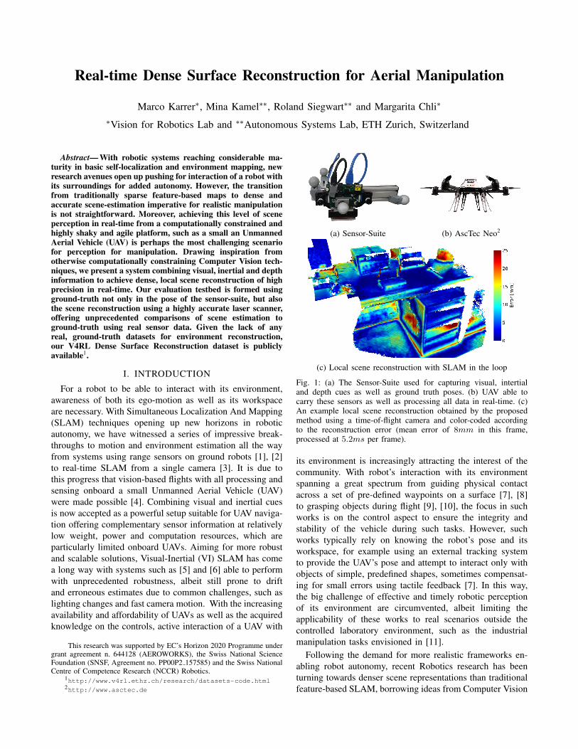
(c) Local scene reconstruction with SLAM in the loop
Fig. 1: (a) The Sensor-Suite used for capturing visual, intertialand depth cues as well as ground truth poses. (b) UAV able tocarry these sensors as well as processing all data in real-time. (c)An example local scene reconstruction obtained by the proposedmethod using a time-of-flight camera and color-coded accordingto the reconstruction error (mean error of 8mm in this frame,processed at 5.2ms per frame).
its environment is increasingly attracting the interest of thecommunity. With robot’s interaction with its environmentspanning a great spectrum from guiding physical contactacross a set of pre-defined waypoints on a surface [7], [8]to grasping objects during flight [9], [10], the focus in suchworks is on the control aspect to ensure the integrity andstability of the vehicle during such tasks. However, suchworks typically rely on knowing the robot’s pose and itsworkspace, for example using an external tracking systemto provide the UAV’s pose and attempt to interact only withobjects of simple, predefined shapes, sometimes compensat-ing for small errors using tactile feedback [7]. In this way,the big challenge of effective and timely robotic perceptionof its environment are circumvented, albeit limiting theapplicability of these works to real scenarios outside thecontrolled laboratory environment, such as the industrialmanipulation tasks envisioned in [11].
Following the demand for more realistic frameworks en-abling robot autonomy, recent Robotics research has beenturning towards denser scene representations than traditionalfeature-based SLAM, borrowing ideas from Computer Vision
and Photogrammetry. A significant milestone in this directionwas the emergence of the Microsoft Kinect camera, whichpaved the way to a variety affordable depth sensors able toprovide dense depth images at high frame rates. Of particularinterest are also the new generations of more compact andcheaper Time of Flight (ToF) cameras.
KinectFusion [12] pioneered real-time dense scene recon-struction using a Kinect camera proposing to maintain adiscretized Signed Distance Function (SDF) to fit a surfaceto the scene. Aiming to address the lack of scalabilityof [12], [13] proposed a movable reconstruction volume,while [14] proposed the use of a discretized Octree scenerepresentation. Putting SLAM in the loop of dense sceneestimation, [15] proposed an RGB-D SLAM system builton dense image alignment and an Octree-based mapping ofthe underlying SDF. However, despite the visually appealingscene reconstructions that they produce, all aforementionedworks make use of power-hungry GPUs to compensate forthe otherwise unaffordable cost of computation. As the useof such computational power is prohibitive onboard lowpower and low payload platforms such as UAVs, most recentresearch focuses on bringing such techniques on the basis ofaffordable CPU processing. In this direction, [16] demon-strated real-time CPU-only capability based their earlierwork [15], while single-camera CPU-only reconstructionshave also made their debut [17], albeit with significantly lessaccurate and less robust frameworks.
In realistic manipulation tasks, for example to clean asurface from oxidation, it is imperative to have a timely,dense and accurate estimation of the robot’s workspace.This is especially the case in aerial manipulation, wherethe base of the manipulator, instead of firmly mounted ona rigid structure, is attached on a highly agile and shakyUAV, highlighting the need for real-time and precise densescene estimation before any manipulation task can be carriedout successfully. With this challenge in mind, in this paperwe propose a novel system, which estimates the pose ofthe sensor-suite in real-time using monocular-inertial SLAMand produces a dense, local scene reconstruction based on[16] using sensing cues from a depth sensor (Figure 1). Weevaluate our system on a variety of challenging surfacesand camera motions with respect to scene ground truthobtained by millimetre-accurate laser scans from a LeicaMS503 station. While several datasets exist in the literature,recording depth values from RGB-D sensors (e.g. [18]), tothe best of our knowledge, there are no datasets offeringground truth for evaluating the scene reconstruction at thislevel of accuracy. The dataset used in this paper, consistingof data from our hand-held multi-sensor setup (Figure 1a),as well as millimetre-precise ground truth for both the poseof the sensor-suite using a Vicon4 Tracking system and thescene using the Leica laser scanner is available online1.Accompanying this paper, a video is available summarizingour approach.
3http://leica-geosystems.com4http://www.vicon.com
VI sensor RS sensor ToF sensor
TECHNOLOGY
Monochromeglobal-shutterCMOS, IMU
RGB imaging, IRdepth imaging
Laser(VCSEL)depth imaging
WEIGHT 130g 35g 18g
RANGE - 0.5 − 5m indoors,varies outdoors 0.1− 4m
POWER 5W 1− 1.6W 300mWIMAGING
RESOLUTION480× 752
RGB: 1920×1080,IR: 640× 480
172× 224
TABLE I: Specifications of the sensors used to produce the localscene reconstruction. While the VI is sufficient for pose estimation,we discuss the use of either the RS or the ToF for dense sceneestimation. Note that the resolutions correspond to the maximalsupported values.
II. METHOD
A. Sensor Setup
Since our framework is intended for the use with an aerialrobot, besides accuracy, the weight and power consumptionof the sensors are also important specifications. In thispaper the Intel RealSense R2005 (RS), and the novel Time-of-Flight (ToF) camera CamBoard pico flexx6 from PMDare used for the depth perception. For the onboard poseestimation, the Visual-Inertial (VI) sensor [19] which consistof a stereo camera pair and a time-synchronized InertialMeasurement Unit (IMU) is used. In Table I specificationsfor the sensors used are shown. We use Vicon, an externalvisual 6 degree of freedom measurement system consisting ofa constellation of multiple infrared cameras, tracking markerssuch as the ones in Figure 1a at 100 Hz at millimeter-precision. This is used to provide ground truth for the posesof the sensor-suite. The setup with the ToF mounted and themarkers for the external tracker is shown in Figure 1a.For clarity, we refer to the visual image captured by the RSas the “RS image”, and equivalently for the ToF we refer tothe amplitude image as the “ToF image”. Note that both ofthese sensors also provide a corresponding “depth image”.
B. Calibration
In a first step, the camera intrinsics as well as the rigidbody transformation between the IMU and the camera arecalibrated using the framework of [20], [21] and [22]. Theintrinsic parameters of the depth sensors are used as providedby the manufacturer, which were verified using the cameracalibration application from MATLAB’s Computer VisionToolbox.The remaining calibration parameters, namely the rigid bodytransformations from the left VI-camera (C) to depth sensor(D), which can be either the ToF or the RS, and fromthe external tracker-body (B) to the camera are depicted inFigure 2. To compute these transformations, a set of imagesj = 1, . . . , J of a checkerboard calibration pattern (P ) aretaken, while simultaneously capturing the pose of the tracker-body (TBW ) from the Vicon, along with the amplitude imagefor the ToF or the RGB image of the RS. Instead of just
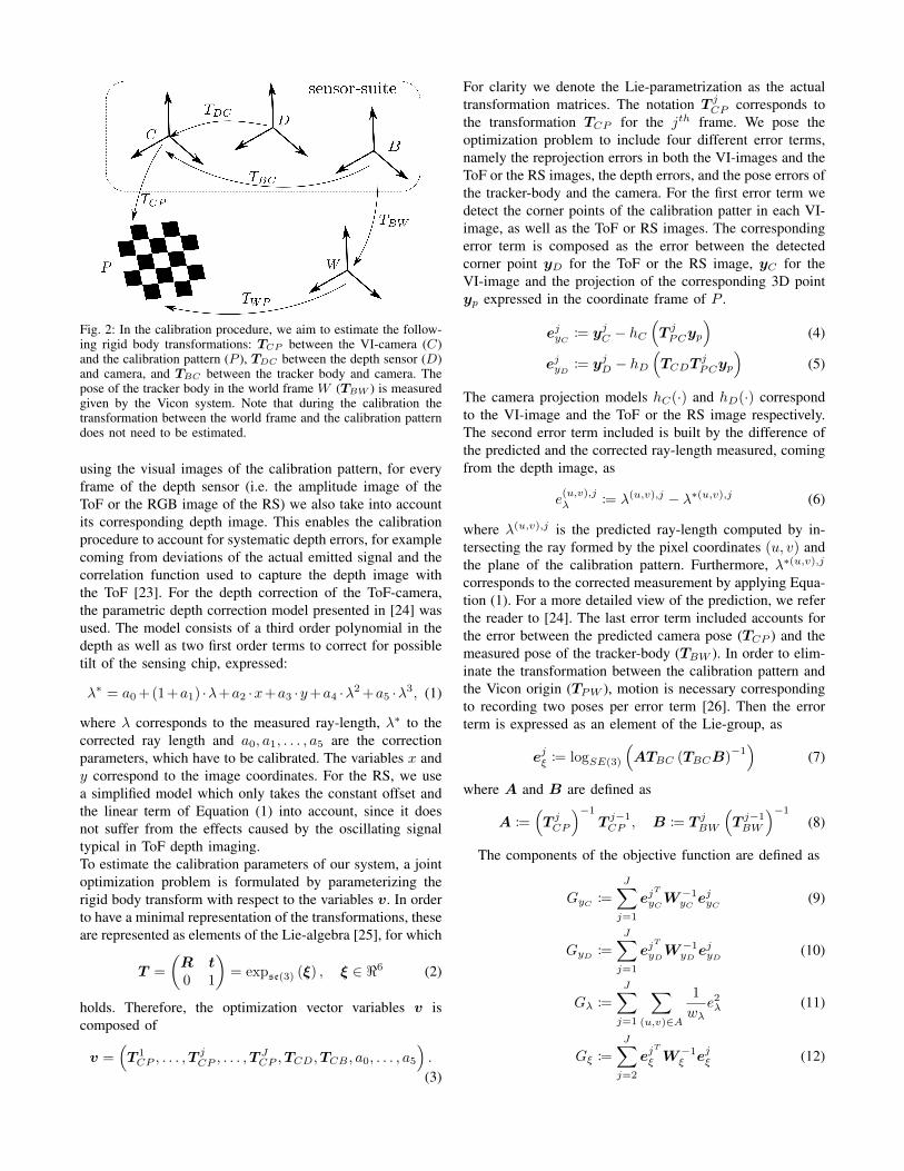
Fig. 2: In the calibration procedure, we aim to estimate the follow-ing rigid body transformations: TCP between the VI-camera (C)and the calibration pattern (P ), TDC between the depth sensor (D)and camera, and TBC between the tracker body and camera. Thepose of the tracker body in the world frame W (TBW ) is measuredgiven by the Vicon system. Note that during the calibration thetransformation between the world frame and the calibration patterndoes not need to be estimated.
using the visual images of the calibration pattern, for everyframe of the depth sensor (i.e. the amplitude image of theToF or the RGB image of the RS) we also take into accountits corresponding depth image. This enables the calibrationprocedure to account for systematic depth errors, for examplecoming from deviations of the actual emitted signal and thecorrelation function used to capture the depth image withthe ToF [23]. For the depth correction of the ToF-camera,the parametric depth correction model presented in [24] wasused. The model consists of a third order polynomial in thedepth as well as two first order terms to correct for possibletilt of the sensing chip, expressed:
where λ corresponds to the measured ray-length, λ∗ to thecorrected ray length and a0, a1, . . . , a5 are the correctionparameters, which have to be calibrated. The variables x andy correspond to the image coordinates. For the RS, we usea simplified model which only takes the constant offset andthe linear term of Equation (1) into account, since it doesnot suffer from the effects caused by the oscillating signaltypical in ToF depth imaging.To estimate the calibration parameters of our system, a jointoptimization problem is formulated by parameterizing therigid body transform with respect to the variables v. In orderto have a minimal representation of the transformations, theseare represented as elements of the Lie-algebra [25], for which
T =
(R t0 1
)= expse(3) (ξ) , ξ ∈ <6 (2)
holds. Therefore, the optimization vector variables v iscomposed of
v =(T 1CP , . . . ,T
jCP , . . . ,T
JCP ,TCD,TCB , a0, . . . , a5
).
(3)
For clarity we denote the Lie-parametrization as the actualtransformation matrices. The notation T jCP corresponds tothe transformation TCP for the jth frame. We pose theoptimization problem to include four different error terms,namely the reprojection errors in both the VI-images and theToF or the RS images, the depth errors, and the pose errors ofthe tracker-body and the camera. For the first error term wedetect the corner points of the calibration patter in each VI-image, as well as the ToF or RS images. The correspondingerror term is composed as the error between the detectedcorner point yD for the ToF or the RS image, yC for theVI-image and the projection of the corresponding 3D pointyp expressed in the coordinate frame of P .
ejyC := yjC − hC(T jPCyp
)(4)
ejyD := yjD − hD(TCDT
jPCyp
)(5)
The camera projection models hC(·) and hD(·) correspondto the VI-image and the ToF or the RS image respectively.The second error term included is built by the difference ofthe predicted and the corrected ray-length measured, comingfrom the depth image, as
e(u,v),jλ := λ(u,v),j − λ∗(u,v),j (6)
where λ(u,v),j is the predicted ray-length computed by in-tersecting the ray formed by the pixel coordinates (u, v) andthe plane of the calibration pattern. Furthermore, λ∗(u,v),j
corresponds to the corrected measurement by applying Equa-tion (1). For a more detailed view of the prediction, we referthe reader to [24]. The last error term included accounts forthe error between the predicted camera pose (TCP ) and themeasured pose of the tracker-body (TBW ). In order to elim-inate the transformation between the calibration pattern andthe Vicon origin (TPW ), motion is necessary correspondingto recording two poses per error term [26]. Then the errorterm is expressed as an element of the Lie-group, as
ejξ := logSE(3)
(ATBC (TBCB)
−1)
(7)
where A and B are defined as
A :=(T jCP
)−1
T j−1CP , B := T jBW
(T j−1BW
)−1
(8)
The components of the objective function are defined as
GyC :=
J∑j=1
ejT
yCW−1yC e
jyC (9)
GyD :=
J∑j=1
ejT
yDW−1yD e
jyD (10)
Gλ :=
J∑j=1
∑(u,v)∈A
1
wλe2λ (11)
Gξ :=
J∑j=2
ejT
ξ W−1ξ ejξ (12)
where A denotes the pixels of the depth image correspondingto the area covered by the calibration pattern. The weight-matrices WyC ,WyD and Wξ were chosen to be diagonalwith the corresponding variance expected considering thecalibration of the individual sensors or the manufacturer’sspecification on the uncertainty. The scalar weight wλ cor-responds to the noise variance of the depth sensor. Theobjective function is composed as:
G = GyC +GyD +Gλ +Gξ (13)
For the initialization of the camera poses the linear solutionto the extrinsics problem is used. The transformationbetween the depth sensor and the camera is initializedusing a least squares solution to the reprojection error on asubset of the calibration images. The initial guess for thetransformation between the tracker-body and the camera isobtained using the algorithm of [26]. For the optimizationof the objective function we use the Levenberg-Marquardtalgorithm.
C. Surface Reconstruction
We employ the framework of [16] to estimate the surfaceand extend this to account for any priors on the uncertaintyof the depth measurements as well as with an efficientmethod for performing a local reconstruction as elaboratedin Section II-D. At the core of the approach of [16] liesthe Octree structure, which at its leafs, called “bricks” (b),stores the value of the SDF in a 83 voxel volume. With thearrival of a new depth image, the corresponding brick forevery pixel is looked up and put into a queue. The queueis then iterated over and for every voxel contained inside ofthe brick, its position p in the world frame transformed intothe frame of the depth sensor pD. The measured point iscomputed using the linear inverse projection model h−1
D (·)on the undistorted depth image and the depth measurementZ(u, v) at pixel coordinates (u, v), as
pobs = h−1D (u, v, Z(u, v)) (14)
Due to the use of a truncated version of the SDF, defined as
∆D = max {min {Φ, |pD − pobs|} ,−Φ} (15)
where Φ is the truncation threshold and the multiscaleapproach, the number of bricks queued per frame are limited.The update of the stored distance values D(p, t) at the voxelposition p at time t is performed as a weighted runningaverage
D(p, t) =D(p, t− 1)W (p, t− 1) + ∆Dw(∆D)
w(∆D) +W (p, t− 1)(16)
Where W (p, t) corresponds to the accumulated weight atposition p and time t. For the weight increment w(∆D)different weighting schemes can be used as presented in [27].In [16] w(∆D) is constant for areas in front of the surface
and decreases linearly until zero behind the surface, i.e.
w(∆D) =
1 , if ∆D < δΦ−∆D
Φ−δ , if ∆D ≥ δ and ∆D ≤ Φ
0 , if ∆D > Φ
(17)
where δ can be seen as an allowed penetration depth of themeasurement. This weighting scheme solely relies on thegeometric distance to the measurement, but does not take anyadditional information into account. A simple noise estimatefor example for a ToF camera can be obtained as describedby [28]. Since the ToF camera used provides informationabout the noise level of each pixels, we propose a weightingscheme to incorporate these in the weighting function usingit as a scaling factor. Assuming a noise value σ(u, v) at pixelcoordinates (u, v), we compute a scaling factor according to
fσ =
{1 , if σ(u, v) ≤ σminσmin
σ(u,v) , if σmin < σ(u, v),(18)
where σmin is a parameter that can be chosen according tothe expected noise of the sensor. In this way, we aim totake the sensor’s estimated uncertainty into account whenweighting the different incoming votes of the voxels. Thisresults to more informed estimation of the surface, providingrobustness to common bottlenecks, for example too obliqueangles of incidence. The adapted weighting scheme is de-fined as:
w(∆D) = fσ · w(∆D) (19)
This simple scheme allows to incorporate sensor-specificuncertainty measurement, which in case of our ToF camerais available anyway, without degrading the computationalefficiency of the estimation. For the RS, we use the uniformweighting scheme according to Equation (17).The SDF representation has a large memory footprint,which e.g. limits cooperative interactions between multipleagents due to limited bandwidth. Therefore, and also forvisualization purposes, the algorithm of [16] keeps track ofthe updated bricks and performs a re-meshing on those areasusing an adapted version of a marching cubes algorithm inorder to account for the multiscale approach. For a detailedexplanation of the meshing algorithm, we refer to [16].
D. Surface Reconstruction using SLAM Poses
In order to use the reconstruction algorithm with SLAMposes, typically subject to drift, we implemented a schemewhich is able to maintain a locally accurate scene estimate.We implement this by introducing a visibility constraint inthe sense that we only keep the portion of the reconstruction,which received measurements within the time horizon thand discard the rest. This is done by keeping track of thetime-stamp of updated bricks and maintaining the local scenereconstruction within th with respect to the current camerapose. We denote Bs as the set of bricks used for the surfaceestimation at the current time and Bo as the bricks to beupdated. The notation t(bi) corresponds to the latest time-stamp that brick bi was updated. The actual voxels grouped
inside the brick bi are indicated by pj , which corresponds tothe voxel center coordinates. The update procedure is shownin Algorithm 1. The time horizon th influences the behaviorof the algorithm. For larger th during exploratory motion,drift of the SLAM system result in larger reconstructionerrors and higher computational cost as more bricks need tobe tracked, i.e. the size of Bs increases. On the other hand,if the chosen th is too small, even quick deviations fromthe current viewpoint, e.g. by wind disturbances, can resultin loss of the previous reconstruction. The reconstruction
Algorithm 1 Time Window for Local ReconstructionBo := all bricks observed from the current poset← current time-stampfor all bi ∈ Bo do
if bi /∈ Bs thenadd bi to Bs
for all bi ∈ Bs doif bi ∈ Bo then
t(bi)← tfor all pj ∈ bi do
update W (pj , t)update D(pj , t)
else if (t− t(bi)) > th thenremove bi from Bs
Bo ← ∅
algorithm itself is agnostic to the SLAM technique used. Forthe pose estimation in our system, we use the frameworkproposed by [29], which uses the sensor readings of boththe IMU as well as the camera input streaming from theVI-sensor. The system is based on sparse features on aset of keyframes as well as the incorporation of IMUmeasurements into a local graph. The window of keyframesis kept bounded by marginalizing out old keyframes. Thisallows the algorithm to run in real time on a CPU, whilemaintaining an accurate pose estimate. However, due to thelocal keyframe approach the system is still prone to globaldrift. The framework can be run using multiple cameras or asa monocular system. Motivated by the lower computationalcomplexity, while maintaining a comparable performance,here we use the monocular version of the algorithm for stateestimation.
III. EXPERIMENTAL RESULTS
A. V4RL Dense Surface Reconstruction Dataset
In order to evaluate the performance of the system in termsof accuracy, a dataset consisting of the VI data, as wellas the data of the depth sensor (RS or ToF) and the poseof the tracker-body from the Vicon system were recorded.Complementary, the observed scene was scanned using aLeica MS50 laser scanner from multiple viewpoints in orderto obtain ground truth for the scene, against which we cancompare the estimated reconstruction. This dataset, whichincludes scene and poses’ ground truth for the first time, ispublicly available1.
Fig. 3: A view of the Desk scene used for the evaluation togetherwith the Leica MS50 station used to obtain the ground truth scenereconstruction.
Fig. 4: The registered laser scans of mm-precision used as sceneground truth, left: Pipe structure, right: Desk scene
We choose two different scenes to evaluate the system;one generic desk sequence containing objects of differenttexture and material (e.g. affecting their reflectance prop-erties) as shown in Figure 3, as well as a more industrialobject consisting of a Pipe structure typical in an industrialinspection scenario (ground truth reconstruction in Figure 4).The recordings were made using a hand-held setup in order toease testing different types of motions (i.e. of different speed,shaky, different viewpoints) as well as to avoid changes ofthe scene setup due to the airstream of a UAV.
The scene ground truth was captured by 8 separate scansfor the Desk scene with a total number of approximately10M points and 6 scans for the Pipe structure with 2.5Mpoints in total. The scans were pre-aligned by localizingthe Leica station with respect to a set of known markersin the room. The final alignment was performed using theIterative Closest Point (ICP) algorithm on adjacent scans,incrementally building the ground truth point cloud. Outlierfiltering using radius search was applied on the obtainedpoint clouds, while points with low neighborhood supportwere also removed. The final ground truth point clouds forboth scenes are shown in Figure 4.
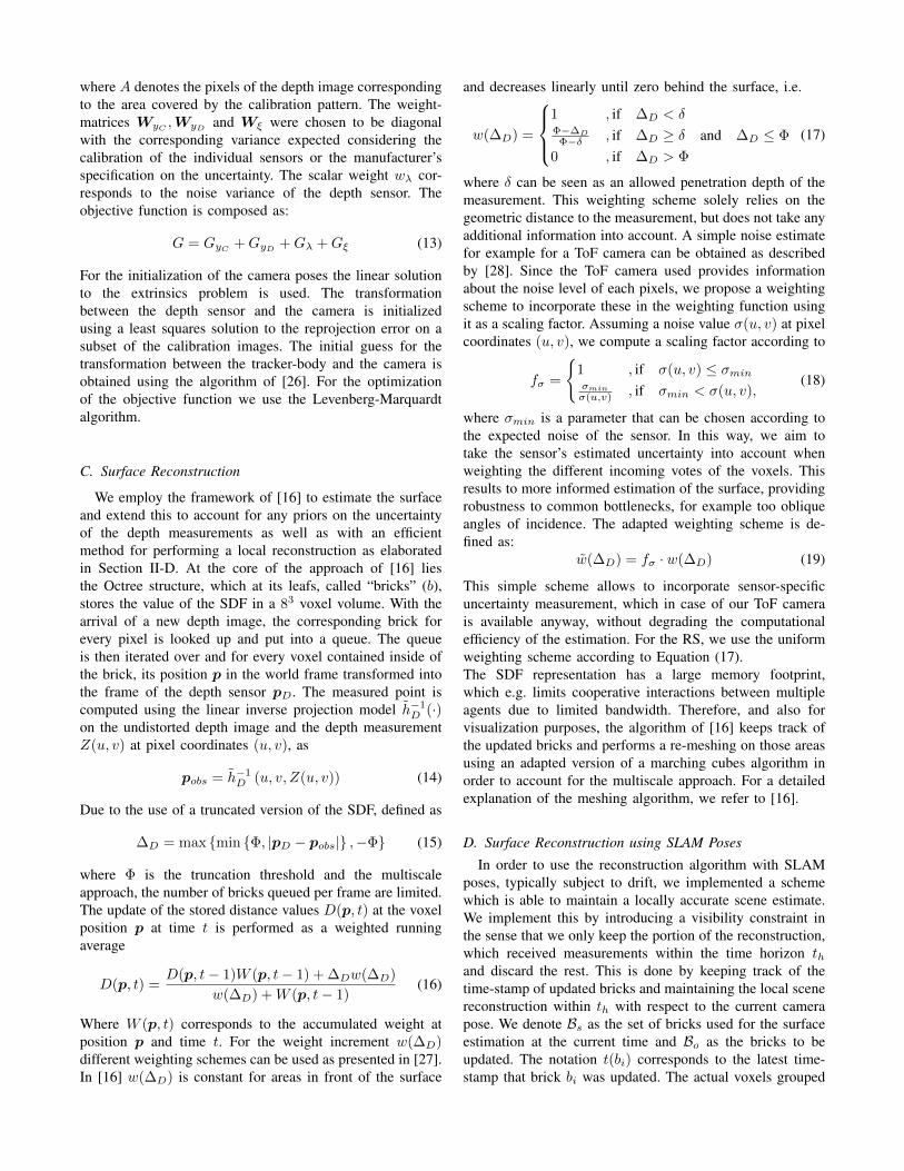
The properties of the sequences used are listed in Table II.Note that the trajectories using the ToF and the RS are similarin each case but cannot be identical due to the hand-heldsetup.
B. Reconstruction Accuracy (Global)
To quantitatively evaluate the reconstruction accuracy iso-lating it from any pose errors, the scenes are reconstructed
TABLE II: Properties and naming convention of the V4RL DenseSurface Reconstruction dataset.
Fig. 5: Resulting reconstruction error using ground truth poses alongwith the ToF depth measurements on the Desk scene, while applyingthe proposed weighting scheme.
using the ground truth poses from the Vicon system. Thereconstruction is performed by fusing the full data sequencein the system for every trajectory. The voxel resolution atthe finest level is chosen to have a side length of 6mm.The transformation between the world frame (of the Viconsystem) and the origin of the scene ground truth is onlyknown approximately, since the world frame origin of theVicon system can only be selected manually. Therefore,for every comparison we perform an ICP alignment of theestimated reconstruction to the ground truth. Although theobtained reconstruction is represented as a mesh, we considerits vertex points for the alignment. For the evaluation process,we compute the distance of every vertex of the reconstructionto its Nearest Neigbhor (NN) in the ground truth point cloud.In order to correct for regions, where no ground truth data isavailable (due to occlusions, shiny surfaces, etc.), we do notconsider vertices whose NN is further away than a certainmaximal distance dmax. The distance dmax was chosen to be50mm for the Desk scene and 30mm for the Pipe structure,respectively. In Figure 5, an example of a reconstructioncolor-coded with respect to the NN-distance is shown. TheNN-based errors are recorded for every sequence of the twoscenes, using both the RS and the ToF. For the ToF camera,both the standard weighting scheme of [16] as well as ourproposed weighting system (according to Section II-C) areevaluated. The reconstruction accuracies achieved in each
(a) Desk Scene
(b) Pipe Structure
Fig. 6: Average reconstruction error using ground truth poses. Note:the labels d1− d4 and p1− p4 correspond to the sequences in thedataset defined in Table II
case are summarized in Figure 6. On both the Desk scene aswell as the Pipe structure, the RS achieves higher accuracycompared to the ToF. This is caused by the higher resolution(2×) of and the higher frame rate (3×) of the RS, whichresults in a higher information density. For the ToF ourproposed weighting scheme improves the accuracy on allsequences on average by 10% up to a maximal improvementof 17%. The error level on the Desk scene is higher which iscaused not only by the larger size of the scene, but also dueto the different materials and larger variety in the angles ofincidence. Furthermore, in the sequences of the Pipe structureall areas of the object are observed from a similar numberof views and viewpoints, whereas for the Desk scene someregions are only viewed quickly, while others are observedmore thoroughly.
C. Local Reconstruction with SLAM in the loop
To evaluate the estimated reconstruction when usingSLAM for the pose estimation, we applied the time windowdiscussed in Section II-D resulting to a local estimation ofthe scene. The time window th for this procedure was setthe constant value of 3s, which gives some tolerance toshaky motions of the camera when observing an area, whilestill keeping the region of the estimated reconstruction smallenough to avoid significant motion drift. Instead of the global
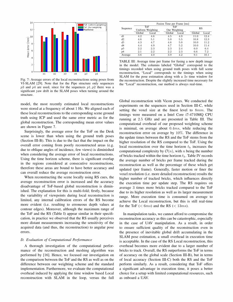
Fig. 7: Average errors of the local reconstructions using poses fromVI-SLAM [29]. Note that for the Pipe structure only sequencesp3 and p4 are used, since for the sequences p1, p2 there was asignificant yaw drift in the SLAM poses when turning around thestructure.
model, the most recently estimated local reconstructionswere stored at a frequency of about 1 Hz. We aligned each ofthese local reconstructions to the corresponding scene groundtruth using ICP and used the same error metric as for theglobal reconstruction. The corresponding mean error valuesare shown in Figure 7.
Surprisingly, the average error for the ToF on the Deskscene is lower than when using the ground truth poses(Section III-B). This is due to the fact that the impact on theoverall error coming from poorly reconstructed areas (e.g.due to oblique angles of incidence, few views) is diminishedwhen considering the average error of local reconstructions.Using the time horizon scheme, there is significant overlapin the regions considered at consecutive reconstructions,therefore these areas are bound to have better accuracy andcan overall reduce the average reconstruction error.
When reconstructing the scene locally using RS cues, theaverage reconstruction error is increased and the accuracydisadvantage of ToF-based global reconstruction is dimin-ished. The explanation for this is multi-fold; firstly, becausethe variability of viewpoints during local reconstruction islimited, any internal calibration errors of the RS becomemore evident (i.e. resulting to erroneous depth values atcontour edges). Moreover, although the maximum range ofthe ToF and the RS (Table I) appear similar in their specifi-cation, in practice we observed that the RS usually perceivesmore distant measurements increasing the sensitivity of theacquired data (and thus, the reconstruction) to angular poseerrors.
D. Evaluation of Computational Performance
A thorough investigation of the computational perfor-mance of the reconstruction and meshing algorithm wasperformed by [16]. Hence, we focused our investigation onthe comparison between the ToF and the RS as well as on thedifference between our weighting scheme and the standardimplementation. Furthermore, we evaluate the computationaloverhead induced by applying the time window based Localreconstruction with SLAM in the loop, versus the full
Sequence
Fusion Time per Frame [ms]ToF ToF RSUniform Weighting Our Weighting
Global Local Global Local Global Locald1 4.2 4.6 4.5 4.9 11.0 12.4d2 4.6 5.1 5.0 5.5 10.8 12.3d3 4.3 4.7 4.6 5.0 10.0 11.2d4 4.4 4.9 4.7 5.2 10.0 11.4p3 2.2 2.3 2.3 2.4 6.0 6.4p4 2.1 2.2 2.2 2.3 6.6 7.2Average 3.6 4.0 3.9 4.2 9.1 10.1
TABLE III: Average time per frame for fusing a new depth imagein the model. The columns labeled “Global” correspond to thetimings recorded when using ground truth poses with full scenereconstruction, “Local” corresponds to the timings when usingSLAM for the pose estimation along with a 3s time window forthe reconstruction. Despite the slightly increased time necessary forthe “Local” reconstruction, our method is always real-time.
Global reconstruction with Vicon poses. We conducted theexperiments on the sequences used in Section III-C, whilesetting the voxel size at the finest level to 8mm. Thetimings were measured on a Intel Core i7-4710MQ CPUrunning at 2.5 GHz and are presented in Table III. Thecomputational overhead of our proposed weighting schemeis minimal, on average about 0.4ms, while reducing thereconstruction error on average by 10%. The difference inthe update times between the RS and the ToF stems from thehigher resolution of the RS compared to the ToF. Using thelocal reconstruction over the time horizon th increases thecomputational complexity by O(n), with n being the numberof bricks tracked within the time horizon th. Table IV recordsthe average number of bricks per frame tracked during thereconstruction as well as the percentage of these which getupdated (per frame). Generally, faster motion or finer thevoxel resolution (i.e. more detailed reconstruction) results thehigher number of tracked bricks, which influences directlythe execution time per update step. The RS requires onaverage 3 times more bricks tracked compared to the ToFdue to its higher resolution as well as its larger measurementrange. More execution time is consumed on average toachieve the Local reconstruction, but this is still real-timefor the ToF (< 6ms) and the RS (< 13ms).
In manipulation tasks, we cannot afford to compromise thereconstruction accuracy as this can be catastrophic, especiallyin the case of UAV manipulation. As a result, in orderto ensure sufficient quality of the reconstruction even inthe presence of inevitable global drift accumulating in theSLAM pose estimation, a small overhead in execution timeis acceptable. In the case of the RS Local reconstruction, thisoverhead becomes more evident due to a larger number ofbricks to track. Overall, the RS outperforms the ToF in termsof accuracy on the global scale (Section III-B), but in termsof local accuracy (Section III-C) both the RS and the ToFperform similarly. As a result, considering that ToF offersa significant advantage in execution time, it poses a betterchoice for a setup with limited computational resources, suchas onboard a UAV.
Sequence Number of Bricks Tracked Updated Bricks [%]ToF RS ToF RS
TABLE IV: Average number of bricks tracked using the timewindow based Local reconstruction, and the percentage of bricksupdated related to the number of tracked bricks.
IV. CONCLUSIONS AND FUTURE WORK
In this paper we present a system capable of accuratelyreconstructing a local scene in real-time, suitable for ma-nipulation tasks even from a highly agile platform, such asa UAV. Fusing depth cues at frame rate, while estimatingthe pose of the sensor-suite using visual-inertial SLAM,our experimental evaluation on a variety of challengingscenarios reveals the high fidelity of the system achievingreconstruction accuracy of the order of 10mm on average.
A thorough evaluation of the proposed approach waspresented assessing the accuracy of the obtained 3D recon-struction both on a global scale using ground truth posesand ground truth scene reconstruction, as well as for localreconstructions using poses obtained by a nominal visual-inertial SLAM system. As no such testbed (with real sensingdata and scene ground truth) exists in the literature, werelease our dataset consisting of visual, inertial and depthdata from a time-of-flight and an RGBD camera, as well aspose and scene ground truth of millimeter precision. Futurework includes employing this reconstruction framework toperform simple manipulation tasks from a UAV, as well asresearch into UAV path planning for viewpoints promisingmore accurate reconstructions.
REFERENCES
[1] J. Leonard and H. Durrant-Whyte, Directed Sonar Sensing for MobileRobot Navigation. Norwell, MA, USA: Kluwer Academic Publishers,1992.
[2] J. Castellanos, J. Tardos, and G. Schmidt, “Buildiong a Global Map ofthe Environment of a Mobile Robot: The Importance of Correlations,”in Proceedings of the IEEE International Conference on Robotics andAutomation (ICRA), 1997.
[3] A. J. Davison, N. D. Molton, I. Reid, and O. Stasse, “MonoSLAM:Real-time single camera SLAM,” IEEE Transactions on Pattern Anal-ysis and Machine Intelligence (PAMI), vol. 29, no. 6, pp. 1052–1067,2007.
[4] S. Weiss, M. W. Achtelik, S. Lynen, M. C. Achtelik, L. Kneip, M. Chli,and R. Siegwart, “Monocular Vision for Long-term MAV Navigation:A Compendium,” Journal of Field Robotics (JFR), vol. 30, pp. 803–831, 2013.
[5] M. Bloesch, S. Omari, M. Hutter, and R. Siegwart, “ROVIO: RobustVisual Inertial Odometry Using a Direct EKF-Based Approach,” inProceedings of the IEEE/RSJ Conference on Intelligent Robots andSystems (IROS), 2015.
[6] S. Leutenegger, P. Furgale, V. Rabaud, M. Chli, and R. Siegwart,“Keyframe-based Visual-Inertial SLAM using Nonlinear Optimiza-tion,” in Proceedings of Robotics: Science and Systems (RSS), 2013.
[7] G. Darivianakis, K. Alexis, M. Burri, and R. Siegwart, “HybridPredictive Control for Aerial Robotic Physical Interaction towardsInspection Operations,” in Proceedings of the IEEE InternationalConference on Robotics and Automation (ICRA), 2014.
[8] L. Marconi, R. Naldi, A. Torre, J. Nikolic, C. Huerzeler, G. Caprari,E. Zwicker, B. Siciliano, V. Lippiello, R. Carloni, and S. Stramigioli,“Aerial Service Robots: an Overview of the AIRobots Activity,” inInternational Conference on Applied Robotics for the Power Industry(CARPI), 2012.
[9] P. Pounds, D. Bersak, and A. Dollar, “Grasping From the Air:Hovering Capture and Load Stability,” in Proceedings of the IEEEInternational Conference on Robotics and Automation (ICRA), 2011.
[10] S. Kim, S. Choi, and H. J. Kim, “Aerial Manipulation Using aQuadrotor with a Two DOF Robotic Arm,” in Proceedings of theIEEE/RSJ Conference on Intelligent Robots and Systems (IROS), 2013.
[12] R. Newcombe, S. Izardi, O. Hiliges, D. Molyneaux, D. Kim, A. J.Davison, P. Kohli, J. Shotton, S. Hodges, and A. Fitzgibbon, “Kinect-Fusion: Real-time dense surface mapping and tracking,” in Proceed-ings of the International Symposium on Mixed and Augmented Reality(ISMAR), 2011.
[13] H. Roth and M. Vona, “Moving Volume KinectFusion,” in Proceedingsof the British Machine Vision Conference (BMVC), 2012.
[14] M. Zeng, F. Zhao, J. Zheng, and X. Liu, “A Memory-efficientKinectfusion Using Octree,” in Proceedings of the First InternationalConference on Computational Visual Media, 2012.
[15] F. Steinbruecker, C. Kerl, J. Sturm, and D. Cremers, “Large-ScaleMulti-Resolution Surface Reconstruction from RGB-D Sequences,”in Proceedings of the International Conference on Computer Vision(ICCV), 2013.
[16] F. Steinbruecker, J. Sturm, and D. Cremers, “Volumetric 3D Mappingin Real-Time on a CPU,” in Proceedings of the IEEE InternationalConference on Robotics and Automation (ICRA), 2014.
[17] J. Engel, T. Schops, and D. Cremers, “LSD-SLAM: Large-Scale DirectMonocular SLAM,” in Proceedings of the European Conference onComputer Vision (ECCV), 2014.
[18] J. Sturm, N. Engelhard, F. Endres, W. Burgard, and D. Cremers,“A Benchmark for the Evaluation of RGB-D SLAM Systems,” inProceedings of the IEEE/RSJ Conference on Intelligent Robots andSystems (IROS), 2012.
[19] J. Nikolic, J. Rehder, M. Burri, P. Gohl, S. Leutenegger, P. Furgale,and R. Siegwart, “A synchronized visual-inertial sensor system withFPGA pre-processing for accurate real-time SLAM,” in Proceedingsof the IEEE International Conference on Robotics and Automation(ICRA), 2014.
[20] J. Maye, P. Furgale, and R. Siegwart, “Self-supervised Calibration forRobotic Systems,” in Inteligent Vehicles Symposium (IVS), 2013.
[21] P. Furgale, J. Rehder, and R. Siegwart, “Unified Temporal and Spa-tial Calibration for Multi-Sensor Systems,” in Proceedings of theIEEE/RSJ Conference on Intelligent Robots and Systems (IROS), 2013.
[22] P. Furgale, T. D. Barfoot, and G. Sibley, “Continuous-Time BatchEstimation Using Temporal Basis Functions,” in Proceedings of theIEEE International Conference on Robotics and Automation (ICRA),2012.
[23] D. Lefloch, R. Nair, F. Lenzen, H. Schaefer, L. Streeter, M. J. Cree,R. Koch, and A. Kolb, Time-of-Flight and Depth Imaging. Sensors,Algorithms, and Applications. Springer Berlin Heidelberg, September2013, vol. 8200, ch. Technical Foundation and Calibration Methodsfor Time-of-Flight Cameras, pp. 3–24.
[24] I. Schiller, C. Beder, and R. Koch, “Calibration of a PMD-CameraUsing a Planar Calibration Pattern Together With a Multi-CameraSetup,” in The International Archives of the Photogrametry, RemoteSensing and Spatial Information Sciences, vol. XXXVII, Part B3a.ISPRS Congress, 2008, pp. 297–302.
[25] E. Eade, “Lie Groups for Computer Vision,” http://ethaneade.com/liegroups.pdf, accessed: 2016-02-19.
[26] K. Daniilidis, “Hand-Eye Calibration Using Dual Quaternions,” Inter-national Journal of Robotics Research, vol. 18, pp. 286–298, 1998.
[27] E. Bylow, J. Sturm, C. Kerl, F. Kahl, and D. Cremers, “Real-Time Camera Tracking and 3D Reconstruction using Signed DistanceFunctions,” in Proceedings of Robotics: Science and Systems (RSS),2013.
[28] L. Li, “Time-of-Flight Camera - An Introduction,” White Paper, TexasInstruments, May 2014.
[29] S. Leutenegger, S. Lynen, M. Bosse, R. Siegwart, and P. Furgale,“Keyframe-based visual–inertial odometry using nonlinear optimiza-tion,” in The Internationa Journal of Robotics Research, 2014.


![Stability Control in Aerial Manipulation · grasping for added stability [3]. With the focus of dynamic stability on ground-based mo-bile manipulators, little work has been done in](https://static.documents.pub/doc/80x56/5ebad1922783aa7ac02e13ea/stability-control-in-aerial-manipulation-grasping-for-added-stability-3-with.jpg)
