Real-time digital control of optical interferometersby the mechanical-modulation technique
Fabrizio Barone, Rosario De Rosa, Luciano Di Fiore, Francesco Fusco, Aniello Grado,Leopoldo Milano, and Guido Russo
We discuss the application of digital systems to the automatic control of dual-wave optical interferom-eters. We show that, if the mechanical-modulation technique is used for error-signal extraction, digitaltechniques can be used both for error-signal extraction and for control-signal generation. Therefore,apart from two front/end amplifiers that are necessary to match the dynamics of the detectors andactuators to the dynamics of the analog-to-digital converters and digital-to-analog converters, no otheranalog devices are required. In particular, the mechanical-modulation technique requires the synchro-nous demodulation of the photodiode output signal. Hence we need to implement a digital lock-inamplifier whose algorithm is described here. Finally, we describe one of the possible applications of thisdigital control procedure, such as the control of a classic Mach-Zehnder interferometer in air.
Key words: Interferometers, digital lock-in amplifier, real-time digital control.
1. IntroductionRecently the performances of the digital-control sys-tems have been greatly improved. As a consequencethe number of possible applications is increasing, andamong possible areas of application, the digital auto-matic control of optical interferometers is surely apromising field.
Although many different types of optical interferom-eter exist, actually the basic control scheme is thesame for all of them. In fact the error signals (onefor each degree of freedom to control), obtained bymeans of a suitable error-signal extraction technique,are processed according to a control law to generatesuitable control signals, which are sent to properactuators. We can consider this control procedure toconsist of two main parts, the error-signal extractionand the control-signal generation. Figure 1 shows atypical control system for one degree of freedom.A digital implementation of both of these parts, which
F. Barone, R. De Rosa, F. Fusco, A. Grado, L. Milano, and G.Russo are with the Dipartimento di Scienze Fisiche, Universitd diNapoli "Federico II", Mostra d'Oltremere, Pad. 19-80125 Napoli,Italia. L. Di Fiore is with the Istituto Nazionale di Fisica Nucle-are, sez. Napoli, Italia. The other authors are also with theIstituto Nazionale di Fisica Nucleare.
Received 28 January 1992; revised manuscript received 19 May1994.
depends on the given specifications, is not alwayspossible.
In two previous papers we illustrated the generalmodel we built for describing the digital-control sys-tems, which puts in direct correspondence the quanti-ties that are often given as specifications (i.e., thecontrol band, the dynamic range, the residual outputnoise) with the more direct technical parameters,such as the number of bits of the analog-to-digitalconverters (ADC's) and digital-to-analog converters(DAC's) and the sampling frequency f. 1'2 A directapplication of this model permits one to quantifythese technical parameters and verify the feasibilityof the digital-control system.
Whereas the control-signal generation, obtained bysuitably processing the error signals, is now a stan-dard procedure, the same consideration is not true forthe error-signal extraction. In fact, many analogtechniques exist for the error-signal extraction, whichcan be divided basically into two categories, i.e., directand indirect techniques. With direct techniques oneobtains the error signals for the various degrees offreedom by processing the output signals of quadrant(or more complicated geometric structures) photodi-odes or obtaining quadrature signals by means ofpolarization techniques. With indirect techniquesone obtains the error signals by slightly perturbingthe optical system with known signals and processingthe resulting signals at the photodiode output.Typical techniques of this latter type are, for example,
Fig. 1. Control system scheme for one degree of freedom.
the phase-modulation technique and the mechanical-modulation technique.3 4
In particular, we have digitally implemented themechanical-modulation technique. With this tech-nique, one can obtain the error signals by applying amechanical modulation to the degrees of freedom tocontrol and then synchronously demodulate the pho-todiode output, an operation that requires a lock-inamplifier. Hence one also needs to implement adigital lock-in amplifier to realize a completely digi-tally controlled interferometer. In this way the en-tire control procedure (the error-signal extractionand the control-signal generation) can be expressedby an algorithm that can be software or hardwareimplemented.
We describe the theory of the mechanical-modula-tion technique applied to a general dual-wave opticalinterferometer and the procedure for implementing adigital lock-in amplifier. As an application we illus-trate a digital-control system for the automatic con-trol of a Mach-Zehnder interferometer and discussthe control scheme and the results.
2. Mechanical-Modulation TechniqueThe output light intensity of a perfectly aligneddual-wave interferometer (Michelson, Mach-Zehnder,etc.) can be expressed as a time function of theoptical-path-length difference between the two armsas5
I(t) = Imin + |m2 )[1 + cos +(t)], (1)
where Ima,, and Imin are the maximum and minimumoutput intensities, measured by the output photodi-ode, and 4(t) is given by
.4(t) = A. [12(t) - 11(t)], (2)
where X is the laser-beam wavelength, no is therefraction index (assumed to be equal and constant inthe two arms), and li(t) is the ith arm length, which isvariable with time because of the presence of externalnoise sources. Actually if the interferometer mir-
rors are either mounted on rigid supports or sus-pended to pendular suspensions to reduce the effectsfrom the seismic noise (as in optical interferometersfor gravitational wave detections), each arm lengthli(t) can be written in a general way as the sum of twoterms: a constant term i expressing the ith armlength in the absence of any external noise source anda time-varying term n(t) expressing the ith arm-length changes from the perturbing effects of exter-nal noise sources. Therefore Eq. (2) can be writtenas
4(t) = o [72 + nn2 (t) - 1 1-l(t)]X 2t
= 4rno -= [Al + nl(t)], (3)
where we put AZ = 12 - 11 and n1(t) = n(t) - nt).The relative displacement between the two arms,e(t) = AZ + n(t), is the error signal that is necessaryfor the automatic control system to lock on a fringe.In particular, e(t) = m(X/2), where m is an integer,corresponds to the system locked on the light fringem, whereas e(t) = (2m + 1)(X/4) corresponds to thesystem locked on the dark fringe m (for no = 1).
Although Eq. (1) does not show any difference inthe choice of a dark or a light fringe as a workingpoint, in practice, if the control system needs thephotodiode output signal for the error-signal extrac-tion, the best signal-to-noise ratio for the error signal(and consequently the finest locking) can be obtainedby locking the interferometer on a dark fringe.7This is the case of the mechanical-modulation tech-nique, so it is preferable to lock the interferometer ona dark fringe unless requirements are different.
According to the mechanical-modulation tech-nique, the length of one of the two arms of theinterferometer must be mechanically modulated witha function of the type
where f = (/27r) is the modulating frequency(carrier) and 1m is its amplitude. For example, wecan apply a mechanical modulation to one of the endmirrors of a Michelson interferometer or to one of thecorner mirrors of a Mach-Zehnder interferometer byusing ceramic piezoelectric actuators.
If we assume that Al = (2m + 1)(X/4), ni(t) << ,and Im << , then, for small displacements around adark fringe, the output intensity [Eq. (1)] can beexpressed as (see Appendix A)
{Im. - Imin. 4rno n 2 im,,2I(t) = min + ( I) ) [fA1 2(t) + 1
2
+ 21mni(t)cos i)ct + 2 cos 2wct} . (5)
Equation (5) shows that the output intensity varia-tion I(t) = I(t) - Imi is. proportional to threecomponents:
(1) A low-frequency component with a band equalto the noise power [n1
2(t) + (m /2)].(2) An amplitude-modulated signal 21m nl(t)cos wct.
The amplitude of this signal is proportional to theerror signal nl(t), whereas the band is equal to twicethe band of the error signal n1(t) centered around thecarrier frequency fc.
(3) A constant amplitude oscillating signal at fre-quencyf= 2fc.
Therefore we can extract the error signal by syn-chronously demodulating term (2) of the photodiodeoutput signal.
Although the assumptions made to obtain Eq. (5)appear to be too stringent [A7 = (2m + 1)(X/4),nl(t) << , and Im << A], actually it is always possibleto satisfy them:
Al = (2m + 1)(X/4), (5a)
where Al is by definition a constant quantity, so thatit can easily be made equal to (2m + 1)(X/4) orreduced to Al - (2m + 1)(X/4) << by simply givingan offset to the actuators, once the mean points of theresidual displacements of the mirrors are measured:
n1(t) << X. (5b)
Actually nl(t) << X is not always satisfied, especially in
a suspended interferometer, which means that themechanical-modulation technique does not permitthe extraction of the right error signal at any time.However, there are some intervals of time in whichthis approximation is true, so that if the automaticcontrol system is designed to be fast enough to lockthe system in the useful time ranges, this conditionposes no further problems:
lm << . (5c)
This specification is the easiest to satisfy, because it isindependent of the external noise sources, althoughfor a value of Im that is too small, problems may arisebecause of a poor signal-to-noise ratio of the resultingamplitude-modulated signal.
The procedure for the error-signal extraction bysynchronous demodulation is in Fig. 2. To improvethe signal-to-noise ratio of component (2), the outputphotodiode signal is filtered with a bandpass filter,centered on the carrier frequency fc with a band atleast equal to the error-signal band nl(t). The signalis then multiplied by a constant amplitude-oscillatingsignal with the same frequency and phase of thecarrier. Finally, it is filtered with a low-pass filter tosuppress the resulting high-frequency components,and an output signal proportional to the error signalis obtained:
e() k Ima -Imin)(4mn l)2 lfl(t) = k n(t), (6)
where ko and k are constants that include thesensitivity of the photodiode, the gains of thefront/end amplifiers, and the gains of the filters used.
There are three main constraints to satisfy for themechanical-modulation technique to function cor-rectly:
(1) It is necessary to avoid the superposition ofthe spectra of the three components of Eq. (5). Thisconstraint can be satisfied by the proper choice of themechanical-modulation frequency f Furthermoreit is convenient to locate the spectrum of component(2) of Eq. (5) in a region of the spectrum of theintensity I(t) characterized by very little intrinsicnoise. This choice permits one to obtain the maxi-mum signal-to-noise ratio for the error signal.
((t) + t )+ L+21m,nj(t)coswt + +e cos2wct
oc ni(t)
Fig. 2. Synchronous demodulation of the photodiode output signal for the mechanical-modulation technique.
(2) We cannot generally obtain synchronous de-modulation by simply using the same signal thatmechanically modulates the arm length, because,although the frequency can be the same, the phasedifference is not zero and, in general, a time-varyingquantity. As a result the amplitude of the errorsignal can be modulated by a signal function of thephase difference (see Section 3). Hence we need alock-in amplifier.
(3) As we can see from Eq. (5), there are someinstants of time in which the amplitude-modulatedsignal [component (2)] disappears or becomes verysmall independently of the amplitude of the errorsignal n(t), resulting in a variable signal-to-noiseratio. The lock-in amplifier must handle this situa-tion correctly.
3. Digital Lock-in AmplifierFor the error-signal extraction we implemented adigital lock-in amplifier 8 9whose structure is reportedin Fig. 3.
The signal coming from the photodiode, describedby Eq. (5), is sampled at a rate f, by the input ADC.To improve the signal-to-noise ratio, this signal isdigitally filtered with a bandpass filter, whose band,which is at least equal to the error-signal band, iscentered around the carrier frequency. The result-ing signal is then multiplied by two digital sinusoidsof frequency fr with a relative phase difference equalto r/2. One of these sinusoids is chosen as aninternal reference frequency.
If we assume that the value of the internal refer-ence frequency coincides exactly with the value of thecarrier, that is, fr = f although not in phase [i.e., witha phase error ~in(n) • 0], then the two resultingsignals, y1(n) and y2(n), filtered with a low-pass filter
(with a band larger than the error signal one) tosuppress the high-frequency components, becomeproportional to the error signal e(n):
ky1(n) = - e(n)cos err(n),
kY2(n) = - e(n)sin 'k'rr(nl),
(7)
(8)
where k is a constant and err(n) is the phase differ-ence between the carrier phase *4,a(n) and the inter-nal reference phase 41ref (n), measured at the output ofthe two low-pass filters. [Note that for discrete timesignals we use the notation y(n) _ y(nT,) = y(n/ f8),where n is the sample number and fs is the samplingfrequency.] Actually err(n) differs from the realphase difference in(n) = car(n) - ref(n) because ofthe presence of the low-pass filters used to suppressthe high-frequency components in order to obtain thequantities y(n) and y2(n). In fact, although theerror signal e(n) does not suffer any change becauseits band is narrower than the low-pass filter'band, thephase-error difference i~n(n) whose band can also bevery large [i.e., consider the case of phase-step changesof q,,(n)] is in practice filtered. Analytically therelationships between tn(n) and krr(n) can be writtengenerally for linear time-invariant systems as thediscrete convolution of 4Pin(n) with the discrete im-pulse response of the digital low-pass filter imple-mentedg(n) as
This procedure reproduces the quadrature tech-nique, which is widely used for synchronous demodu-lation of amplitude-modulated signals with no car-rier.10"11 In particular, yl(n) is also the output of thelock-in amplifier. In fact, if err(n) were a quantityindependent of time, the outputyl(n) would be propor-tional to the error signal e(n) with the maximumsignal-to-noise ratio for *err(n) = 0.
For this purpose it is necessary to extract *err(n)and to design a digital control system that dynami-cally changes the phase of the internal referencefrequency, matching it to the carrier frequency (thephase-locked loop). Therefore two other quantitiesare computed:
_e2(n)
Y3 (n) =y 12(n) + y2
2(n) = k2 (10)
e 2(n)y 4(n) = yl(n)y2(n) = -k 2
- sin 2qlerr(n). (11)8
Dividing y4(n) by y3(n), we are able to obtain smallvalues Of *err(n) by means of the equation
Y4(n) = sin 2kerr(n) = -Err(n). (12)
The phase error 'Jerr(n) is used to generate the controlsignal for matching the phases of the carrier and ofthe internal reference by means of suitable feedback.The equivalent scheme of the digital phase-lockedloop is shown in Fig. 4. It represents a schematicsynthesis of the hearth of the digital lock-in in Fig. 3.The input signal of this scheme is 4,r(n), whereas theerror signal obtained is 4err(n). The low-pass filterblock actually represents the procedure describedabove for the extraction of *err(n), so that the transferfunction G(z) (the z transform) coincides with the
Tcar(z) D'Zi(Z) LorPs
're (z)
9car(Z) q in(Z) I ,\ err(z)
transfer function of the low-pass filter used to obtainy,(n) and y2(n). The feedback consists of two blocks,a filter block and a memory block. The purpose ofthe filter block is to generate suitable control signalsby processing lerr(n), whereas the purpose of thememory block is to memorize the current value of thephase of the internal reference, modifying its valueonly on the basis of the values of the control signals.In particular the filters can be designed according tothe given specifications on the locking speed and onthe final error in the steady-state response to canoni-cal signals, according to the classic control theory(see, for example, Refs. 12-16). For a completeanalytical description of the digital phase-locked loop,see Appendix B.
One can obtain the complete characterization ofthe digital phase-locked loop by analyzing its re-sponse to two input canonical signals, the step func-tion and the ramp function.
In particular, knowledge of the response of thesystem to a step variation of the carrier phase, car(n),
(13)
where i0 is a constant and u(n) is the unitary stepfunction defined as
u nn<{
u(n) = 1 n '(14)
permits the output phase error err(n) to be expressedas
(15)'lIerr(n) = iwo E w(m)u(n -m),m=-
where w(n) is the impulse response of the phase-locked loop. This error always tends asymptoticallyto zero [Perr(n) - 0 for n - o] (see Appendix B).Furthermore, if the feedback transfer function in thez-transform domain has a pole in z = 1, this errortends asymptotically to zero also for a ramp variationof ~c,(n):
*car(n) = or(n) = ionTu(n). (16)
The importance of such a response to a ramp isrelevant in the general case in which the lock-inamplifier has to lock not only in phase but also infrequency (fr • f), which is a necessary operationwhen the carrier frequency is not internally gener-ated by the digital lock-in or when its value istime-varying. In fact, the frequency difference be-tween the internal reference fr and the carrier f,generates a time-dependent phase error,
There are two critical points to this digital ap-proach to a lock-in amplifier:
(1) When the internal reference is locked to thecarrier, the approximation sin 2
krr(n) 2rr(n) ofEq. (12) is true only for small values of the phasedifference i(n). What occurs when large phasevariations are present at the input of the digitallock-in is more involved. Actually the approxima-tion is often still valid. In fact the low-pass filtersused to obtain y1 (n) and y2(n) have the effect of slowlypropagating the input phase error in(n) so that, ifthey are well designed, many samples are necessarybefore the phase error kerr(n) assumes the correctWin(n)- Therefore the value that the phase errorIErr(n) assumes between two consecutive samples canbe much smaller than the effective value of in(n),satisfying in this way the approximation of Eq. (12).At the same time the control procedure tends todecrease the current value of 4in(n). This delay inthe phase error-signal extraction puts an upper limiton the frequency of the phase-error signal ,,(n) thatthe system can correct, which is determined by theband of the low-pass filter used. The same reason-ing is valid for the phase variation because of thefrequency difference between the carrier and theinternal reference frequencies. In fact, only whenthe frequency difference between the carrier and theinternal reference becomes too large, the input phaseerror continues to increase, preventing the systemfrom locking.
(2) The second critical point is due to computationalproblems. In fact, when the input signal becomesvery small, to a limit of zero, the operation of divisionbetween Y4 and Y3 can result in an overflow. Toovercome this problem, we used a cutoff technique:When the value of Y3 is less than a previously definedcutoff value E, that is, Y3 I < , the ratio Y4/Y3 is notevaluated and the phase correction applied is the lastcorrection in which the ratio has been correctlyevaluated. With this procedure the information onthe phase is lost for short time intervals, but itprevents the wrong information from computationalproblems (i.e., large phase spikes) from being used.
As outlined above, the types of filter used dependcase by case on the basis of the given specifications.For this purpose we used a general design procedure,the bilinear transformation, which we discuss inAppendix C.
4. Mach-Zehnder Interferometer ControlBefore proceeding to a description of the automaticcontrol implemented for the Mach-Zehnder in-terferometer, we give a brief description of thedigital system used. This system is part of a VME-bus (IEEE 1014)-based prototype we built to test theperformances of the digital systems that should beused for automatic control of the very long baselineinterferometric Virgo antenna for gravitational wavedetection.6 '1 7-2 ' This antenna is basically a dual-wave interferometer (Michelson interferometer),
whose arms, 3 km long L, are perpendicular andsymmetric. To increase its sensitivity {h =
AL/L = 3 x 10-22(1/Hz)1/2 at 10 Hz}, two Fabry-Perot cavities (3 km long) are placed in the arms ofthe interferometer and a recycling mirror is added toreduce the photon-counting noise by increasing thelight power in the cavities. Moreover, to reduce theseismic noise, all the optical components are sus-pended to multipendular suspensions and all thecomponents are placed in vacuum chambers con-nected by evacuated pipes with a residual pressure of10-8 Torr.
For the digital lock-in amplifier and the processingwe used a digital system that consisted of 12-bitADC's and DAC's, externally triggered with a maxi-mum sampling rate of 125 kHz, controlled by a singleCPU (68040) with a 64-bit floating point arithmetic.The software program that implements the lock-inamplifier and the filters for digitally processing theerror signal are written in C language. A cross-compiler is used for translating this program inassembler language for the CPU.1 2
Although the digital system for the automaticcontrol of dual-wave optical interferometers, basedon the mechanical-modulation technique for error-signal extraction, has in principle no limitations (wehave demonstrated that all the assumptions can besatisfied in practice), the actual limits come from thestatus of the technology.
The first limit comes from the maximum samplingrate f. Actually f does not always depend on theperformances of the ADC used, but often it dependson the computational time required by the algorithmsimplemented. In fact the entire computational pro-cess must be completed in the time interval betweentwo successive acquisitions, which means that thelonger the algorithm is the faster the CPU must be.In our prototype it is the computational time thatputs the upper limit of the value of the sampling rateat fx = 9600 Hz, even if the maximum sam-pling rate for the 12-bit ADC's could be f8 = 125 kHz.
A direct consequence is that the maximum sam-pling rate puts an upper limit on the values of thecarrier f (only if the carrier is digitally generated).In fact, if we assume that at least 8 points arenecessary to generate the carrier (the higher harmon-ics can be filtered with a low-pass filter included in thefront/end amplifiers), this assumption puts an upperlimit to f, = f 8 /8, which in our prototype correspondstotf = 1200 Hz.
The last constraint is on the control band. Infor-mation on the control band comes from direct mea-surement of the noise band nl(t), which depends oneach case. This measurement also gives informationon the zone of the spectrum in which it is useful tolocate the carrier frequency fc. Furthermore there isa general constraint, which is valid for all the digitalsystems used as control systems. In fact the choiceof the sampling frequencyf, fixes a time delay, At = T,(measured from when the datum is sampled by theADC until it is converted by the DAC), which corre-
Fig. 5. Digital-automatic-control scheme for the Mach-Zehnder interferometer.
sponds to a phase lag given by
A+=- f (18)fs
where f is a generic frequency component of thesignal. If this phase lag assumes the value 7r for afrequency for which the open loop gain is still greaterthan 1, the control signal is added in phase with theerror and the negative feedback (stable system) be-comes a positive feedback (unstable system). Generalpractical considerations relate the control band to thesampling frequency as
B < As (19)10
which in our prototype leads to B < 960 Hz.Actually in our case the limit is given by the maxi-mum value of the carrier frequency so that B <600 Hz.
To obtain better performances, we have designedand are now testing a new low-noise high-speeddigital system2' in which not only the speed is im-proved but the noise introduced by the digital systemis also reduced. Its main characteristics are 16-bitADC's and 18-bit DAC's with a maximum samplingfrequency equal to f, = 512 kHz. It would permit amaximum carrier frequency digitally generated to
= 15 kHz and a maximum control band of 7.5 kHz.The automatic control scheme of a Mach-Zehnder
interferometer in air is shown in Fig. 5. The lasersource is a laser diode emitting at a wavelength of= 788 nm, fed with a well-stabilized current source
and temperature controlled by a digital control sys-
tem of the same type used for the digital lock-inamplifier with thermistors as sensors and Peltier cellsas actuators. The output beam of the laser diode iscollimated through a lens and sent to a cubic beamsplitter (to compensate for the path-length opticaldifference between the two arms) that splits it intotwo beams. These beams are then recombined againthrough another cubic beam splitter according to theclassic Mach-Zehnder scheme and sent to a photodi-ode detector. The measured contrast of this interfer-ometer is C = 0.99. Because the laser diode, thebeam splitters, all the mirrors, and the detector aremounted on a rigid base (an optical table with antiseis-mic damping), we have assumed that the only degreeof freedom to control is the longitudinal one. So we
100-n
.2
C/)
1. 0
0 0
Frequency
(Hz)
Fig. 6. Residual spectral density noise in the Mach-Zehnderinterferometer digital control (0-100 Hz).
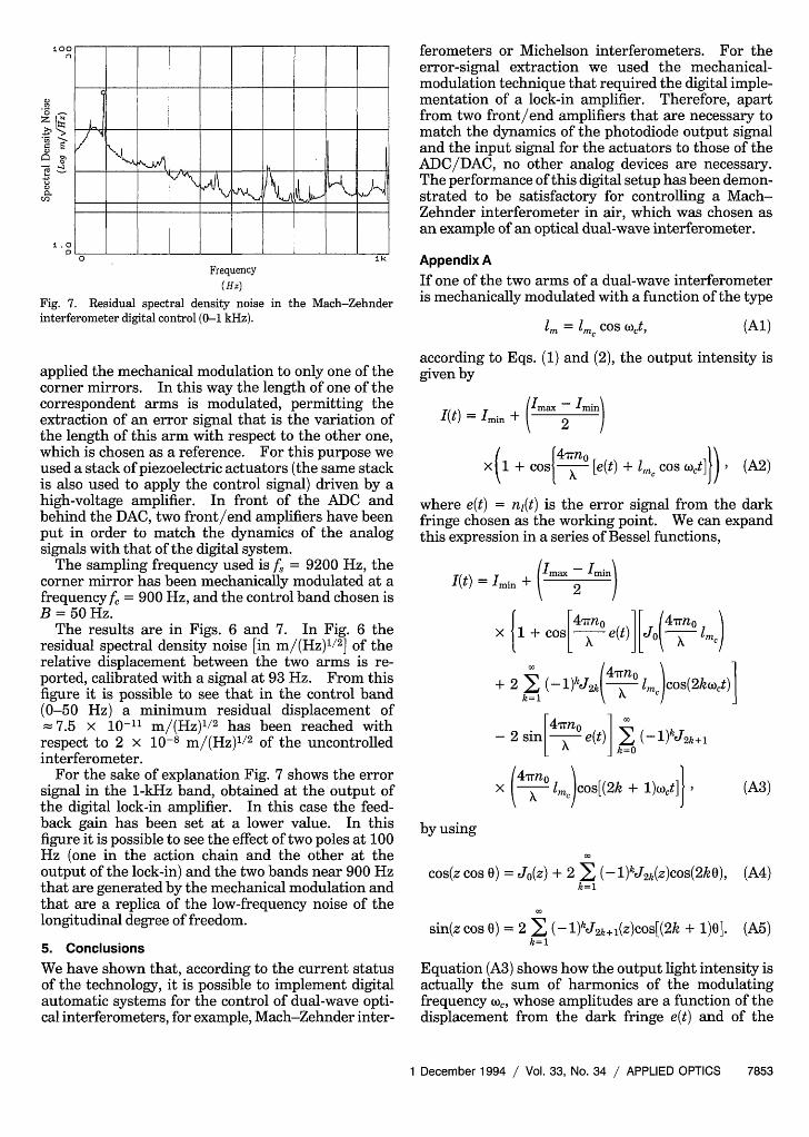
Fig. 7. Residual spectral density noiseinterferometer digital control (0-1 kHz).
in the Mach-Zehnder
applied the mechanical modulation to only one of thecorner mirrors. In this way the length of one of thecorrespondent arms is modulated, permitting theextraction of an error signal that is the variation ofthe length of this arm with respect to the other one,which is chosen as a reference. For this purpose weused a stack of piezoelectric actuators (the same stackis also used to apply the control signal) driven by ahigh-voltage amplifier. In front of the ADC andbehind the DAC, two front/end amplifiers have beenput in order to match the dynamics of the analogsignals with that of the digital system.
The sampling frequency used is f, = 9200 Hz, thecorner mirror has been mechanically modulated at afrequency f, = 900 Hz, and the control band chosen isB = 50 Hz.
The results are in Figs. 6 and 7. In Fig. 6 theresidual spectral density noise [in m/(Hz) 1/2] of therelative displacement between the two arms is re-ported, calibrated with a signal at 93 Hz. From thisfigure it is possible to see that in the control band(0-50 Hz) a minimum residual displacement of= 7.5 x 10⁻¹¹ m/(Hz)1/2 has been reached with
respect to 2 x 10⁻⁸ m/(Hz)1/2 of the uncontrolledinterferometer.
For the sake of explanation Fig. 7 shows the errorsignal in the 1-kHz band, obtained at the output ofthe digital lock-in amplifier. In this case the feed-back gain has been set at a lower value. In thisfigure it is possible to see the effect of two poles at 100Hz (one in the action chain and the other at theoutput of the lock-in) and the two bands near 900 Hzthat are generated by the mechanical modulation andthat are a replica of the low-frequency noise of thelongitudinal degree of freedom.
5. ConclusionsWe have shown that, according to the current statusof the technology, it is possible to implement digitalautomatic systems for the control of dual-wave opti-cal interferometers, for example, Mach-Zehnder inter-
ferometers or Michelson interferometers. For theerror-signal extraction we used the mechanical-modulation technique that required the digital imple-mentation of a lock-in amplifier. Therefore, apartfrom two front/end amplifiers that are necessary tomatch the dynamics of the photodiode output signaland the input signal for the actuators to those of theADC/DAC, no other analog devices are necessary.The performance of this digital setup has been demon-strated to be satisfactory for controlling a Mach-Zehnder interferometer in air, which was chosen asan example of an optical dual-wave interferometer.
Appendix AIf one of the two arms of a dual-wave interferometeris mechanically modulated with a function of the type
1m = Imc cos t, (Al)
according to Eqs. (1) and (2), the output intensity isgiven by
(t) = Imn + (Im.x Ii)
x + Cos 4 xrno [e(t) + mn cos wot] XXkl co~ ~cf (A2)
where e(t) = n(t) is the error signal from the darkfringe chosen as the working point. We can expandthis expression in a series of Bessel functions,
Imax -Iminmm 2 /
X1 + cosL 47no e(t)] JO(4Trnomc)
+ 2 z (-1)kJ2 k( °m)cos(2kwct)]
- 2 sin1 e(t)k ()kJ 2 k+l
x4rrno lmcos[(2k + l)c2ct] , (A3)
by using
cos(z cos 0) = Jo(z) + 2 E (-l)kJ2 k(z)cos(2k 0),k=1
sin(z cos 0) = 2 , (-1)kJ2 k+l(z)cos[(2k + 1)0].k=1
(A4)
(A5)
Equation (A3) shows how the output light intensity isactually the sum of harmonics of the modulatingfrequency (o,, whose amplitudes are a function of thedisplacement from the dark fringe e(t) and of the
amplitude of the modulation im . In particular theamplitudes of the odd harmonics could be directlyproportional to the error signal e(t) if its amplitudewere small.
In fact, assuming that e(t) = nl(t) << A, we can writeEq. (A3) approximating the sine and cosine functionswith the second order of the Taylor series expansionby
I(t) = Imin +,IM.XI + [1 - 1 4 rno2
1+ ii - - n1n2 (t)I
2 )j 2 /
[J (4Jrrno IMl + 2 E ( 1)k J 2k( ilm
tion of discrete time [Eq. (B1)] into a function of acomplex variable z:
Z[ f(k)] = F(z) = z f(k)z-k,k=O
so that the z-transfer function of Eq.written as14
(B2)
(Bi) can be
M
___ i=OH(z) = Xz
1 + I ajz'JJ=1
(B3)
( c ] ( X ) k=O
X eJ2k+1 (47X lm)cos[(2k + 1)(oct] ()
which shows that the error signal is proportional tothe amplitude of the odd harmonics of the modulationintensity. Furthermore, if 1m << , we can expandthe Bessel functions of Eq. (A) in series according to
J2)(z) = (k2 ( k + k + 1) (A7)
where F(k) is the gamma function. Retaining all theterms until the second order, we obtain Eq. (5):
I(t) = Imi + (m 4min)( 4T no) l 12(t) +
+ 21mn(t)cos wot + -m2 cos 2wt .
With regard to the phase-locked loop in Fig. 4, thelow-pass filter can be described by the z transformG(z) such as the filter block (the control signalgeneration) by H(z). In particular, the structures ofG(z) and H(z) depend on the specifications that thelock-in amplifier must satisfy, although these struc-tures are generally described by Eq. (B3). On theother hand, the transfer function of the memoryblock can be explicitly written as
qref(n) = ref(n - 1) + qfh(n), (B4)
which permits an easy evaluation of its transferfunction in the z-transform domain as
-Peon(Z) ZTh(Z) Z - 1
(B5)
Therefore the z transform of the output response ofthe phase-locked loop of Fig. 4 can be written as
(A8)4'err(Z) = (z z - 1)G(z) 4" .(z).
(z-1) + zG(z)H(z)ca(B6)
Appendix B
In conventional linear control the Laplace and Fou-rier transforms are used to obtain the solution tolinear differential equations, which characterize suchcontrol in such a way that the resulting algebraicproblem replaces the more difficult original integra-tion problem.
In linear discrete systems a linear difference equa-tion characterizes the dynamic relationship betweenthe system's input and output signals, e.g.,"4
M N
y(n) = I bix(n - i) - E ajy(n - j).i=0 j=l
(B1)
Analogously, when the z transform is used, thesolution to such difference equations becomes essen-tially algebraic. Just as the Laplace transform trans-fers a function of continuous time into a function of acomplex variable s, the z transform transfers a func-
To determine the asymptotic behavior of Ierr(n) forn - oo, we can now use the final value theorem,14 thatis,
lim Terr(n) = lim(z - 1)err(Z)-fl-rJ,
(B7)
Therefore the asymptotic response to a step inputphase error,
car(n) = *ou(n) - car(Z) = i_ 1) 'o (B8)
is given by
liM err(n) = lim(z - 1) (Z - )G(z) (z__\n[- (z - 1) + zG(z)H(z)J~z 1)
As a conclusion the phase error 4rr(n) tends asymp-totically to zero also for a proportional feedback[H(z) = bo]. Analogously the asymptotic response toa ramp input phase error,
car(n) = 4.or(n) - 4'car(Z) = (Z 1)2T
tends asymptotically to the zero value if and only ifthe feedback transfer function H(z) has at least onepole inz = 1.
Appendix CIn Section 3 we described the general algorithm forthe implementation of a digital lock-in amplifier.Actually this digital lock-in amplifier is a softwareprogram that performs all the operations required bythe procedure in the same way as is usually done forsignal processing. The only part not described is thefilter design procedure. In our prototype we usedthe bilinear transformation.14 The main characteris-tic of the bilinear transformation consists of obtain-ing the correspondent digital filters in the z-trans-form domain with the corresponding expressions inthe Laplace transform domain, which is the classicway of describing analog filters.13
A generic transfer function in the Laplace trans-form domain can be written as
where u(t) is the unitary step function. For t,t2 > 0,
t2
Y(t2) y Atl) = JX(t')U(t2 - t)dt'
J'tl(C6)
and for t,t 2 > t' > 0 we have
t2
Y4t2) - At ) = Jx(t')dt'.tl
(C7)
Assuming that the interval of time (t2 - t) is smallenough, we can approximate the integral of Eq. (C7)as
t2 - t +Y(t2) - Y(tl) = 2 [x* 2 + x*t)] (C8)
and then, setting t2 = nT, and tj = (n - 1)Ts, where T,is the sampling period, we have
(C9)
The z transform of this equation gives
(Cl)
which can be written in a factorized form as
ml 1 m2
H 0 iii ( + -+) i| (S2 + 2 6ziO)nziS + Wn,2i )
H(S) = - / n2
Fl (s + -) II (s2 + 28Piw.nois + (nP, 2)
As an example an integrator can be described as
1Hint(s) = - (C3)
S
or a single-pole low-pass filter as
H(s)= (C4)
S +
In particular the response of the analog ideal integra-tor, described by Eq. (C3), to a signal x(t) is given bythe convolution
y(t) = x(t')u(t - t')dt' = x(t) * u(t), (C5)
TY() - Y(z)z-' = 2 [X(z) + XZ1], (C10)
which gives the z-transfer function of the integrator:
T 1 + Z 'H(z) = 2 1_ (Cll)
Therefore the correspond z transform of a digitalfilter H(z) can be obtained from the expression H(s) by
C 2) means of the following transformation variable:
2 1 -z-1
T 1 + z-'(C12)
Although this transformation was obtained in thecase of an integrator, it is valid for every transferfunction."l
As an example, we can apply the bilinear transfor-mation to the transfer function of the first-ordersystem (low-pass filter) described by Eq. (C4), obtain-ing
H()-= TT(1 + Z-1)
, + 2T + (Ts -
(C13)
which permits the calculation of the coefficients of thefilter compared with Eq. (B3).
Note that the digital filters designed by means ofthe bilinear transformation well approximate the
analog filters only when the frequencies of the polesand zeros are small with respect to the samplingfrequency. In fact the relationship between thefrequencies of the analog poles and zeros AL and theresulting frequencies of the poles and zeros of thedigital filter fD, is given by4
v fATs = tan(7rfD.Ts). (C14)
Therefore, only if the frequencies of the analog polesand zeros are much smaller than the sampling fre-quency will the digital filter reproduce exactly theanalog filter. This is the case of our digital lock-inamplifier.
References1. F. Barone, L. Di Fiore, L. Milano, G. Russo, and S. Solimeno,
"Automatic alignment of a Michelson interferometer," IEEETrans. Nucl. Sci. 39,232-237 (1992).
2. F. Barone, L. Di Fiore, L. Milano, and G. Russo, "A digitalapproach to the automatic control of the interferometricantenna Virgo for gravitational wave detection," Measure-ment Sci. Technol. (to be published).
3. R. T. Denton, "Modulation techniques," in Laser Handbook,F. T. Arecchi and E. 0. Schulz-DuBois, eds. (North-Holland,Amsterdam, 1972), pp. 703-724.
4. H. Melchior, "Demodulation and photodetection techniques,"in Laser Handbook, F. T. Arecchi and E. 0. Schulz-DuBois,eds. (North-Holland, Amsterdam, 1972), pp. 725-835.
5. M. Born and E. Wolf, Principles of Optics (Pergamon, Oxford,1964), Chap. 7, p. 259.
6. The Virgo Project: Proposal for the Italian-French Very LongBaseline Interferometric Antenna for Gravitational WavesDetection (Instituto Nazionale di Fisica Nucleare, Rome, andCentre National de la Recherche Scientifique, Paris, 1989).
7. D. Shoemaker, "Contributions a l'etude de la detection inter-ferometrique des ondes de gravitation," Pd.D dissertation(Centre National de la Recherche Scientifique, Paris, 1987).
8. F. Barone, E. Calloni, R. De Rosa, L. Di Fiore, F. Fusco, L.Milano, and G. Russo, "Digital systems for automatic controlof optical resonators used as gravitational waves detectors," inProceedings of the First European Conference on Smart Struc-ture and Materials, B. Culshaw, P. T. Gardiner, and A.McDonach, eds. (Institute of Physics Publishing, Bristol,England, 1992), pp. 49-53.
9. F. Barone, E. Calloni, R. De Rosa, L. Di Fiore, F. Fusco, L.
Milano, and G. Russo, "Digital alignment control of the Virgointerferometric antenna mirrors," in Proceedings of the TenthItalian Conference on General Relativity and GravitationalPhysics, M. Cerdonio, R. Cianci, M. Francaviglia, and G.Magnano, eds. (World Scientific, Singapore, 1992).
10. M. Girard, Boucles a Verrouillage de Phase (McGraw-Hill,Paris, 1988), Chap. 7, p. 208.
11. F. M. Gardiner, Phaselock Techniques (Wiley, New York,1981), Chap. 3.
12. I. Horowitz, Synthesis of Feedback Systems (Academic, NewYork, 1963).
13. T. Kailath, Linear System (Prentice-Hall, Englewood Cliffs,N.J., 1980).
14. A. V. Oppenheim and R. W. Schafer, Digital Signal Processing(Prentice-Hall, Englewood Cliffs, N.J., 1975).
15. M. Bellanger, Digital Processing of Signals (Wiley, New York,1984).
16. J. A. Cadzow and H. R. Martens, Discrete-Time and ComputerControl Systems (Prentice-Hall, Englewood Cliffs, N.J., 1970).
17. F. Barone, L. Di Fiore, L. Milano, G. Russo and S. Solimeno,"Automatic alignment of a Michelson interferometer," inProceedings of the Seventh Conference on Real Time '91, K. D.Muller, ed. (Institute of Electrical and Electronics Engineers,New York, 1991), pp. 292-297.
18. F. Barone, L. Di Fiore, L. Milano, and G. Russo; "Automaticcontrol of a Michelson interferometer," in Proceedings of theNinth Italian Conference on General Relativity and Gravita-tional Physics, R. Cianci, R. De Ritis, M. Francaviglia, G.Marmo, C. Rubano, and P. Scudellaro, eds. (World Scientific,Singapore, 1990), pp. 562-567.
19. A. Augurio, F. Barone, E. Calloni, L. Di Fiore, L. Milano, G.Russo, and S. Solimeno, "Automatic control system for mir-rors alignment of the interferometric antenna Virgo," inProceedings of the Sixth Marcel Grossmann Meeting on Gen-eral Relativity, H. Sato and T. Nakamura, eds. (World Scien-tific, Singapore, 1992), p. 1453.
20. F. Barone, E. Calloni, R. De Rosa, L. Di Fiore, F. Fusco, L.Milano, G. Russo, and F. Solarino, "A digital approach to theautomatic control of the interferometric antenna Virgo forgravitational wave detection," in Proceedings of the 13thInternational Conference on General Relativity and Gravita-tion, P. W. Lamberti and 0. E. Ortiz, eds. (UniversidadNational de Cordoba, Cordoba, Spain, 1992), p. 204.
21. F. Barone, E. Calloni, R. De Rosa, L. Di Fiore, L. Milano, andG. Russo, "High-speed low-noise digital control system,"IEEE Trans. Nucl. Sci. 41, 190-199 (1994).