Real time Implementation of Sliding mode Based Direct and Indirect Current Control Techniques for Shunt Active Power Filter Rajesh K Patjoshi, Kamalakanta Mahapatra, Venkata Ratnam Kolluru Electronics and Communication Engg.Dept. National Institute of Technology Rourkela, India [email protected]Abstract— This paper presents a new and efficient control algorithm which adopted the voltage source inverter to decrease current harmonics generated by the nonlinear load. The sliding mode control (SMC) is employed with the current control loop to achieve fast dynamics control and a simple proportional-integral (PI) controller is adopted in the outer voltage control loop to achieve slow dynamics control. The proposed scheme implements simplified control algorithms depending on the direct current control (DCC) and indirect current control (ICC) techniques for designing trajectories in sliding mode control based shunt active power filter (SAPF). The performances of the DCC and ICC techniques were verified through a simulation with MATLAB-SIMULINK and real-time implementation in Opal RT- Lab. A comparison has been made between the two configurations showing their topological contrasts and load compensation capabilities under ideal, unbalanced and distorted source voltage conditions. Keywords- current harmonics, fast dynamics, SMC, DCC, ICC, SAP, Real-time. 1 Introduction With the growing and development of modern industry, a various nonlinear and time-varying electronic devices such as inverters, rectifiers, and switching power supplies are widely utilized. These solid-state converters inject harmonics into the power lines and result in serious distortion in the supply current and voltage and decrease the power quality (PQ) [1,2]. This PQ problem provides low efficiency to the distribution line by increasing current and voltage distortions, excessive neutral current and poor power factor. The shunt active power filter (SAPF) has become established with assorted structures and topologies main aim to reduce the current harmonics and reactive power in the power system and enhance the PQ. The continuous development of SAPF can provide different current control techniques and grid synchronization techniques [3,4]. Focusing on the current reference tracking of SAPF, many control methods [5,6,7,8,9]- [10] have been proposed in the literature. The current tracking control can be decided by the dynamic behaviour of SAPF, under various operating conditions. As per [11], two types of current control techniques using sliding mode techniques are compared, and find that active power filter with indirect current control (ICC) technique has a simpler structure and better harmonic treating effect than direct current control (DCC). But this method does not provide any dynamic behaviour of SAPF. Active power filter using the indirect current control method is designed in [12,13]. It does not need compensation current and only considers the supply voltage, source current sa i and DC-link voltage dc v . Therefore, such technique can effectively reduce the current harmonics in balanced supply condition. The reference currents tracking behaviour are enhanced by novel sliding mode control, which can reduce the supply current harmonic content in [14]. Here an integer part of the traditional hysteresis control method is added and reduces the steady tracking error by the designed sliding mode controller. Adaptive sliding mode control method [15] is based on tracking error of harmonics and APF [16] current function in the controller and analysed the robustness and stability of the system is analysed by the simulation analysis. Fuzzy logic-based robust active [17,18]power filter to minimize the harmonics for a wide range of variation of load current under stochastic conditions is considered in-.Sliding mode control can be a high-speed switching feedback control which chooses the suitable switching configuration of the converter like a function of the instantaneous state variables in order to drive the state trajectory onto a switching surface [19,20]. Thus, this control exhibits excellent performance and provides superior tracking performance in all operating conditions. In this paper, a novel sliding mode controller is implemented in SAPF for tracking reference currents using ICC and DCC methods, in balanced, unbalanced as well as distorted voltage condition, and the performance of SAPF is analysed with total harmonic WSEAS TRANSACTIONS on SYSTEMS and CONTROL Rajesh K. Patjoshi, Kamalakanta Mahapatra, Venkata Ratnam Kolluru E-ISSN: 2224-2856 186 Volume 10, 2015
Transcript
Real time Implementation of Sliding mode Based Direct and Indirect Current
Control Techniques for Shunt Active Power Filter
Rajesh K Patjoshi, Kamalakanta Mahapatra, Venkata Ratnam Kolluru
Electronics and Communication Engg.Dept.
National Institute of Technology Rourkela, India
[email protected] Abstract— This paper presents a new and efficient control algorithm which adopted the voltage source inverter to
decrease current harmonics generated by the nonlinear load. The sliding mode control (SMC) is employed with the
current control loop to achieve fast dynamics control and a simple proportional-integral (PI) controller is adopted in
the outer voltage control loop to achieve slow dynamics control. The proposed scheme implements simplified control
algorithms depending on the direct current control (DCC) and indirect current control (ICC) techniques for designing
trajectories in sliding mode control based shunt active power filter (SAPF). The performances of the DCC and ICC
techniques were verified through a simulation with MATLAB-SIMULINK and real-time implementation in Opal RT-
Lab. A comparison has been made between the two configurations showing their topological contrasts and load
compensation capabilities under ideal, unbalanced and distorted source voltage conditions.
Keywords- current harmonics, fast dynamics, SMC, DCC, ICC, SAP, Real-time.
1 Introduction With the growing and development of modern
industry, a various nonlinear and time-varying electronic devices such as inverters, rectifiers, and switching power supplies are widely utilized. These solid-state converters inject harmonics into the power lines and result in serious distortion in the supply current and voltage and decrease the power quality (PQ) [1,2]. This PQ problem provides low efficiency to the distribution line by increasing current and voltage distortions, excessive neutral current and poor power factor.
The shunt active power filter (SAPF) has become established with assorted structures and topologies main aim to reduce the current harmonics and reactive power in the power system and enhance the PQ. The continuous development of SAPF can provide different current control techniques and grid synchronization techniques [3,4]. Focusing on the current reference tracking of SAPF, many control methods [5,6,7,8,9]- [10] have been proposed in the literature. The current tracking control can be decided by the dynamic behaviour of SAPF, under various operating conditions. As per [11], two types of current control techniques using sliding mode techniques are compared, and find that active power filter with indirect current control (ICC) technique has a simpler structure and better harmonic treating effect than direct current control (DCC). But this method does not provide any dynamic behaviour of SAPF. Active power filter using the indirect current control method is designed in [12,13]. It
does not need compensation current and only considers
the supply voltage, source current sai and DC-link
voltage dcv . Therefore, such technique can effectively
reduce the current harmonics in balanced supply condition. The reference currents tracking behaviour are enhanced by novel sliding mode control, which can reduce the supply current harmonic content in [14]. Here an integer part of the traditional hysteresis control method is added and reduces the steady tracking error by the designed sliding mode controller. Adaptive sliding mode control method [15] is based on tracking error of harmonics and APF [16] current function in the controller and analysed the robustness and stability of the system is analysed by the simulation analysis.
Fuzzy logic-based robust active [17,18]power filter to minimize the harmonics for a wide range of variation of load current under stochastic conditions is considered in-.Sliding mode control can be a high-speed switching feedback control which chooses the suitable switching configuration of the converter like a function of the instantaneous state variables in order to drive the state trajectory onto a switching surface [19,20]. Thus, this control exhibits excellent performance and provides superior tracking performance in all operating conditions.
In this paper, a novel sliding mode controller is implemented in SAPF for tracking reference currents using ICC and DCC methods, in balanced, unbalanced as well as distorted voltage condition, and the performance of SAPF is analysed with total harmonic
WSEAS TRANSACTIONS on SYSTEMS and CONTROLRajesh K. Patjoshi,
Kamalakanta Mahapatra, Venkata Ratnam Kolluru
E-ISSN: 2224-2856 186 Volume 10, 2015
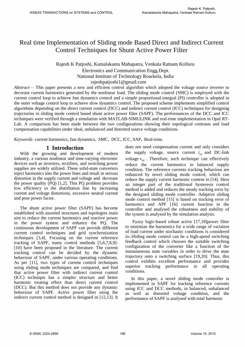
Fig.1 Functional block diagram of SAPF
distortion (THD) of source current in the above three operating conditions of supply voltage. Here MATLAB-SIMULINK results are validated with real-time performance analysis in the RT-LAB simulator. It is one of the most promising real-time simulation tools for all practical applications.
Organization of the paper is as follows: Section II focuses on the development of shunt active power filter with the control strategy of active power filter. In Section III the performances of DCC and ICC are analyzed by means of a simulation platform with MATLAB-SIMULINK. In Section IV real time Opal-RT results are presented. Finally, the most relevant conclusions of this paper are summarized in Section V.
2 Development of Shunt Active Power
Filter The functional diagram of a shunt active power filter,
based on a voltage source converter, for the compensation of current harmonics generated by the nonlinear load is shown in Fig.1. A three phase voltage source inverter is employed as a shunt active power filter. The inverter is controlled through two controllers. A fast inner loop is used to control the shape of the line currents, forcing them to be of the same shape, and in phase with, the phase voltages. The inner current loop is based on a sliding-mode controller, which is conceptually
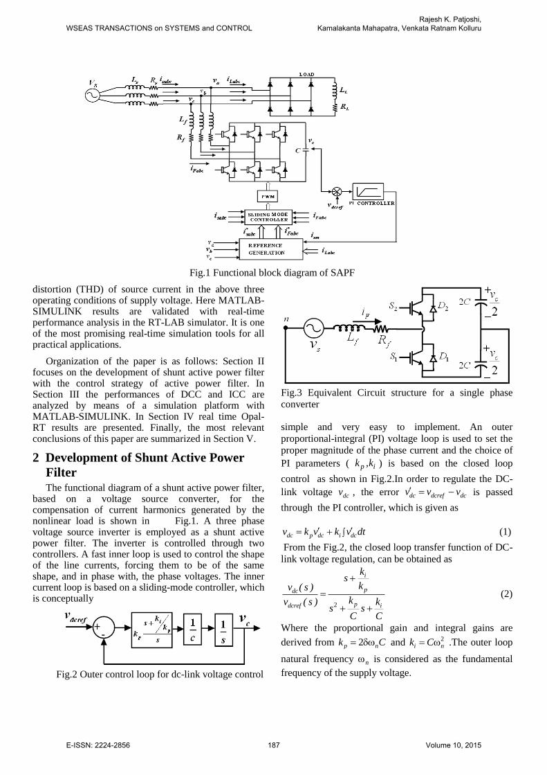
Fig.2 Outer control loop for dc-link voltage control
Fig.3 Equivalent Circuit structure for a single phase
converter
simple and very easy to implement. An outer
proportional-integral (PI) voltage loop is used to set the
proper magnitude of the phase current and the choice of
PI parameters ( p ik ,k ) is based on the closed loop
control as shown in Fig.2.In order to regulate the DC-
link voltage dcv , the error dc dcref dcv v v is passed
through the PI controller, which is given as
dc p dc i dcv k v k v dt (1)
From the Fig.2, the closed loop transfer function of DC-
link voltage regulation, can be obtained as
2
i
pdc
p idcref
ks
kv ( s )
k kv ( s )s s
C C
(2)
Where the proportional gain and integral gains are
derived from 2p nk C and 2i nk C .The outer loop
natural frequency n is considered as the fundamental
frequency of the supply voltage.
WSEAS TRANSACTIONS on SYSTEMS and CONTROLRajesh K. Patjoshi,
Kamalakanta Mahapatra, Venkata Ratnam Kolluru
E-ISSN: 2224-2856 187 Volume 10, 2015
3 Sliding Modes and Equivalent Control
The single phase Model of Fig. 3 does not take into
consideration the shift in the voltage of the common
capacitor node relative to the neutral of the source and
this leads to a valid sliding-mode control law. If a
switching function u is defined such that 1u when
either S1 or D1 is conducting, and 1u when either S2
or D2 is conducting, then the inductor current is given
by
2
fs cFF
f f f
Rv vdiu i
dt L L L (3)
An expression for capacitor voltage taking into account the ripple due to compensating currents can be written as
1[ ]
2
c Fa Fb Fca b c
dv i i iu u u
dt C C C (4)
Where au , bu , cu are the independent controls for
phases a, b, and c, respectively, and Fai , Fbi , Fci are the
compensating currents for phases a, b, and c,
respectively. The filter can be
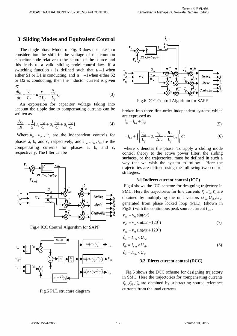
Fig.4 ICC Control Algorithm for SAPF
Fig.5 PLL structure diagram
Fig.6 DCC Control Algorithm for SAPF
broken into three first-order independent systems which
are expressed as
sx Lx Fxi i i (5)
2
fsx cLx x Fx
f f f
Rv vi u i dt
L L L
(6)
where x denotes the phase. To apply a sliding mode control theory to the active power filter, the sliding surfaces, or the trajectories, must be defined in such a way that we wish the system to follow. Here the trajectories are defined using the following two control strategies.
3.1 Indirect current control (ICC)
Fig.4 shows the ICC scheme for designing trajectory in
SMC. Here the trajectories for line currents , ,sa sb sci i i are
obtained by multiplying the unit vectors , ,sa sb scU U U
generated from phase locked loop (PLL), (shown in
Fig.5.) with the continuous peak source current msI .
sin( )
sin( 120 )
sin( 120 )
sa m
sb m
sc m
v v t
v v t
v v t
(7)
m
m
m
sa s sa
sb s sb
sc s sc
i I U
i I U
i I U
(8)
3.2 Direct current control (DCC)
Fig.6 shows the DCC scheme for designing trajectory
in SMC. Here the trajectories for compensating currents
, ,Fa Fb Fci i i are obtained by subtracting source reference
currents from the load currents.
WSEAS TRANSACTIONS on SYSTEMS and CONTROLRajesh K. Patjoshi,
Kamalakanta Mahapatra, Venkata Ratnam Kolluru
E-ISSN: 2224-2856 188 Volume 10, 2015
Fa sa la
Fb sb lb
Fc sc lc
i i i
i i i
i i i
(9)
The sliding surfaces are chosen according to ICC
and DCC schemes and are given by,
[ ] 0x sa sai i (For Indirect Current Control)
[ ] 0y Fa Fai i (For Direct Current Control)
To assure that the system can be maintained on the
sliding surface, it must be shown that there is a natural
control which satisfies 0 at all times, i.e., for all
values that the state may experience. It u is within the
natural control's bounds of the physical system for 0 ,
and then it is possible to remain on the sliding surface at
all times and maintain perfect tracking. Setting 0x
or 0y , the equivalent control can be found to be
2f fLx xn sxeqx Fx
f c
R Ldi v diu i
dt L dt L v
(10)
The natural control limits of the circuit are
1 1equ . To satisfy 0 , the discontinuous control
law can be seen
If 0 then 1u (11)
IF 0 then 1u
4 Simulation Results and Analysis The control units have been tested using MATLAB-
SIMULINK according to the structure shown in Fig.4 and Fig.6. A three phase diode bridge rectifier feeding RL load is considered as nonlinear load. The parameters
used in the simulation are shown in Table 1, where fR
and fL correspond to the link inductor model, C is the
capacitance of dc bus, dcrefv is the reference DC bus
voltage, PK , iK are the PI-controller constants, and rmsV
is the rms value of the source voltage.
Table 1
(Simulation Parameters)
rmsV 360V dcrefv 600V
LR 6.6 fR 1
LL 22 mH fL 2.7mH
C 1800 F pK 0.1273
sR and sL 0.1Ω and
0.1mH iK 4.5000
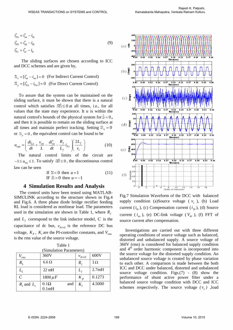
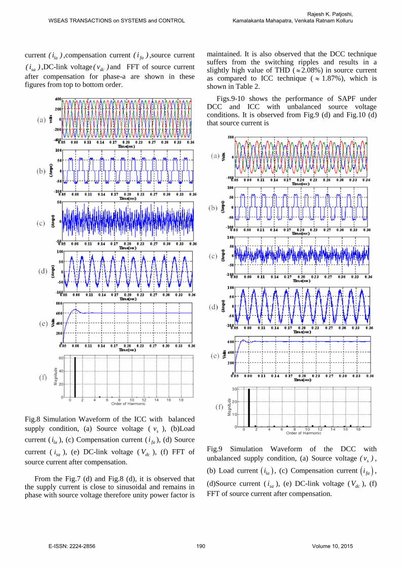
Fig.7 Simulation Waveform of the DCC with balanced
supply condition (a)Source voltage ( sv ), (b) Load
current ( lai ), (c) Compensation current ( fai ), (d) Source
current ( sai ), (e) DC-link voltage ( dcV ), (f) FFT of
source current after compensation.
Investigations are carried out with three different
operating conditions of source voltage such as balanced, distorted and unbalanced supply. A source voltage of 360V (rms) is considered for balanced supply condition and 4
th order harmonic component is incorporated into
the source voltage for the distorted supply condition. An unbalanced source voltage is created by phase variation to each other. A comparison is made between the both ICC and DCC under balanced, distorted and unbalanced source voltage condition. Figs.(7) - (8) show the performance of shunt active power filter under a balanced source voltage condition with DCC and ICC
schemes respectively. The source voltage s( v ) ,load
WSEAS TRANSACTIONS on SYSTEMS and CONTROLRajesh K. Patjoshi,
Kamalakanta Mahapatra, Venkata Ratnam Kolluru
E-ISSN: 2224-2856 189 Volume 10, 2015
current la( i ) ,compensation current fa( i ) ,source current
sa( i ) ,DC-link voltage dc( v )and FFT of source current
after compensation for phase-a are shown in these figures from top to bottom order.
Fig.8 Simulation Waveform of the ICC with balanced
supply condition, (a) Source voltage ( sv ), (b)Load
current ( lai ), (c) Compensation current ( fai ), (d) Source
current ( sai ), (e) DC-link voltage ( dcV ), (f) FFT of
source current after compensation.
From the Fig.7 (d) and Fig.8 (d), it is observed that
the supply current is close to sinusoidal and remains in phase with source voltage therefore unity power factor is
maintained. It is also observed that the DCC technique suffers from the switching ripples and results in a slightly high value of THD ( 2.08%) in source current as compared to ICC technique ( 1.87%), which is shown in Table 2.
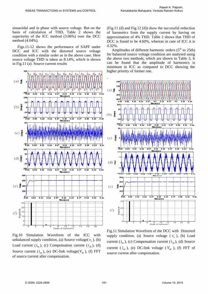
Figs.9-10 shows the performance of SAPF under DCC and ICC with unbalanced source voltage conditions. It is observed from Fig.9 (d) and Fig.10 (d) that source current is
Fig.9 Simulation Waveform of the DCC with
unbalanced supply condition, (a) Source voltage s( v ) ,
(b) Load current lai , (c) Compensation current fai ,
(d)Source current ( sai ), (e) DC-link voltage ( dcV ), (f)
FFT of source current after compensation.
WSEAS TRANSACTIONS on SYSTEMS and CONTROLRajesh K. Patjoshi,
Kamalakanta Mahapatra, Venkata Ratnam Kolluru
E-ISSN: 2224-2856 190 Volume 10, 2015
sinusoidal and in phase with source voltage. But on the basis of calculation of THD, Table 2 shows the superiority of the ICC method (3.06%) over the DCC method (4.04%).
Figs.11-12 shows the performance of SAPF under DCC and ICC with the distorted source voltage condition with a similar order as in the above case. Here source voltage THD is taken as 8.14%, which is shown in Fig.11 (a). Source current results
Load current ( lai ), (c) Compensation current ( fai ), (d)
Source current ( sai ), (e) DC-link voltage( dcV ), (f) FFT
of source current after compensation.
(Fig.11 (d) and Fig.12 (d)) show the successful reduction
of harmonics from the supply current by having on
approximation of 4% THD. Table 2 shows that THD of
DCC is found to be 4.60%, whereas in case of ICC it is
4.32%. Amplitudes of different harmonic orders (5
th to 25th)
for balanced source voltage condition are analysed using the above two methods, which are shown in Table 3, It can be found that the amplitude of harmonics is minimum in ICC as compared to DCC showing the higher priority of former one.
.
Fig.11 Simulation Waveform of the DCC with Distorted
supply condition, (a) Source voltage ( sv ), (b) Load
current ( lai ), (c) Compensation current ( fai ), (d) Source
current ( sai ), (e) DC-link voltage ( dcV ), (f) FFT of
source current after compensation.
WSEAS TRANSACTIONS on SYSTEMS and CONTROLRajesh K. Patjoshi,
Kamalakanta Mahapatra, Venkata Ratnam Kolluru
E-ISSN: 2224-2856 191 Volume 10, 2015
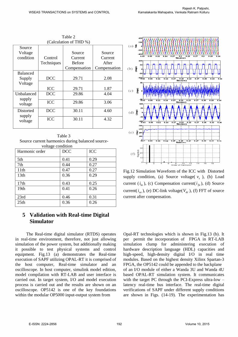
Table 2
(Calculation of THD %)
Table 3
Source current harmonics during balanced source-
voltage condition
Harmonic order DCC ICC
5th 0.41 0.29
7th 0.44 0.27
11th 0.47 0.27
13th 0.36 0.29
17th 0.43 0.25
19th 0.41 0.26
23rd 0.46 0.31
25th 0.36 0.26
Fig.12 Simulation Waveform of the ICC with Distorted
current ( lai ), (c) Compensation current( fai ), (d) Source
current( sai ), (e) DC-link voltage( dcV ), (f) FFT of source
current after compensation.
5 Validation with Real-time Digital
Simulator
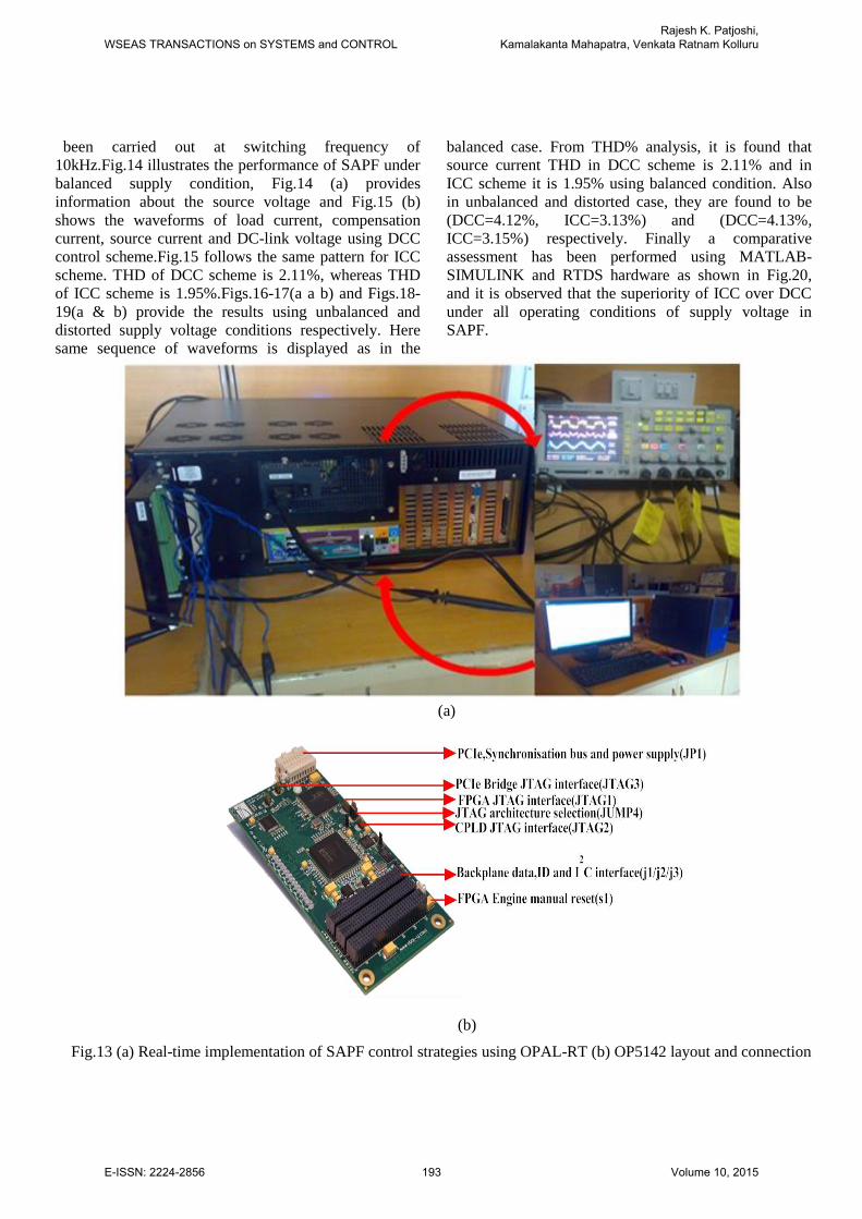
The Real-time digital simulator (RTDS) operates
in real-time environment, therefore, not just allowing
simulation of the power system, but additionally making
it possible to test physical systems and control
equipment. Fig.13 (a) demonstrates the Real-time
execution of SAPF utilizing OPAL-RT it is comprised of
the host computer, Real-time simulator and an
oscilloscope. In host computer, simulink model edition,
model compilation with RT-LAB and user interface is
carried out. In target system, I/O and model execution
process is carried out and the results are shown on an
oscilloscope. OP5142 is one of the key foundations
within the modular OP5000 input-output system from
Opal-RT technologies which is shown in Fig.13 (b). It
per permit the incorporation of FPGA in RT-LAB
simulation clump for administering execution of
hardware description language (HDL) capacities and
high-speed, high-density digital I/O in real time
modules. Based on the highest density Xilinx Spartan-3
FPGA, the OP5142 could be appended to the backplane
of an I/O module of either a Wanda 3U and Wanda 4U
based OPAL-RT simulation system. It communicates
with the target PC through the PCI-Express ultra-low –
latency real-time bus interface. The real-time digital
verifications of SAPF under different supply conditions
are shown in Figs. (14-19). The experimentation has
Source
Voltage
condition
Control
Techniques
Source
Current
Before
Compensation
Source
Current
After
Compensation
Balanced
Supply
Voltage
DCC
29.71
2.08
ICC
29.71
1.87
Unbalanced
supply
voltage
DCC 29.86 4.04
ICC 29.86 3.06
Distorted
supply
voltage
DCC 30.11 4.60
ICC 30.11 4.32
WSEAS TRANSACTIONS on SYSTEMS and CONTROLRajesh K. Patjoshi,
Kamalakanta Mahapatra, Venkata Ratnam Kolluru
E-ISSN: 2224-2856 192 Volume 10, 2015
been carried out at switching frequency of
10kHz.Fig.14 illustrates the performance of SAPF under
balanced supply condition, Fig.14 (a) provides
information about the source voltage and Fig.15 (b)
shows the waveforms of load current, compensation
current, source current and DC-link voltage using DCC
control scheme.Fig.15 follows the same pattern for ICC
scheme. THD of DCC scheme is 2.11%, whereas THD
of ICC scheme is 1.95%.Figs.16-17(a a b) and Figs.18-
19(a & b) provide the results using unbalanced and
distorted supply voltage conditions respectively. Here
same sequence of waveforms is displayed as in the
balanced case. From THD% analysis, it is found that
source current THD in DCC scheme is 2.11% and in
ICC scheme it is 1.95% using balanced condition. Also
in unbalanced and distorted case, they are found to be
(DCC=4.12%, ICC=3.13%) and (DCC=4.13%,
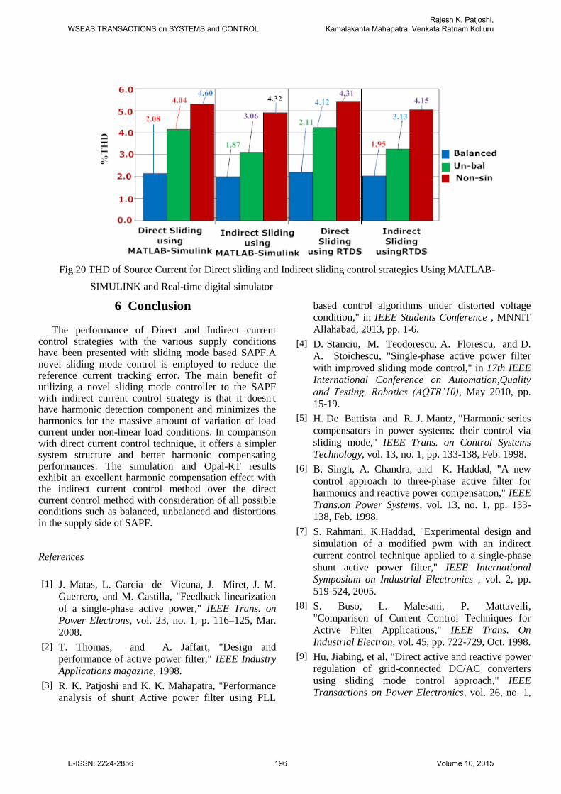
ICC=3.15%) respectively. Finally a comparative
assessment has been performed using MATLAB-
SIMULINK and RTDS hardware as shown in Fig.20,
and it is observed that the superiority of ICC over DCC
under all operating conditions of supply voltage in
SAPF.
(a)
(b)
Fig.13 (a) Real-time implementation of SAPF control strategies using OPAL-RT (b) OP5142 layout and connection
WSEAS TRANSACTIONS on SYSTEMS and CONTROLRajesh K. Patjoshi,
Kamalakanta Mahapatra, Venkata Ratnam Kolluru
E-ISSN: 2224-2856 193 Volume 10, 2015
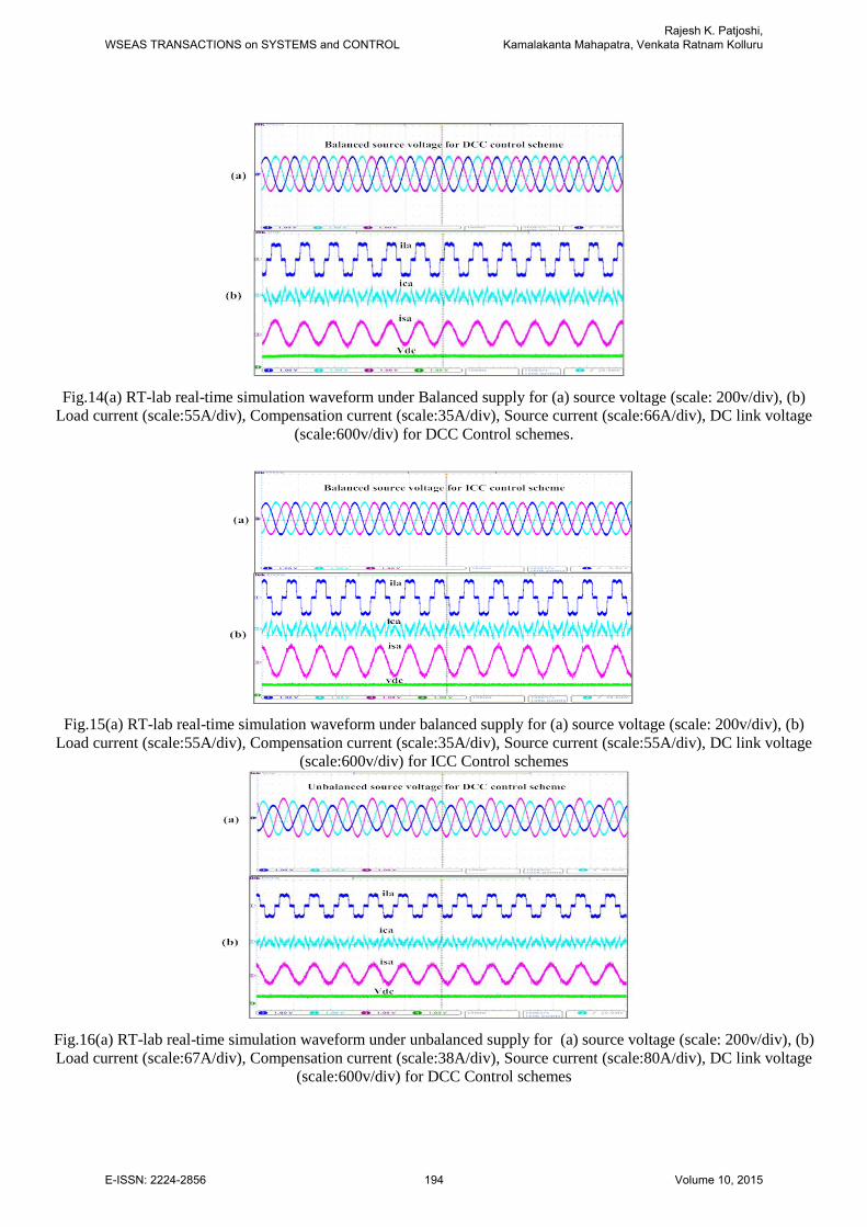
Fig.14(a) RT-lab real-time simulation waveform under Balanced supply for (a) source voltage (scale: 200v/div), (b)
Load current (scale:55A/div), Compensation current (scale:35A/div), Source current (scale:66A/div), DC link voltage
(scale:600v/div) for DCC Control schemes.
Fig.15(a) RT-lab real-time simulation waveform under balanced supply for (a) source voltage (scale: 200v/div), (b)
Load current (scale:55A/div), Compensation current (scale:35A/div), Source current (scale:55A/div), DC link voltage
(scale:600v/div) for ICC Control schemes
Fig.16(a) RT-lab real-time simulation waveform under unbalanced supply for (a) source voltage (scale: 200v/div), (b)
Load current (scale:67A/div), Compensation current (scale:38A/div), Source current (scale:80A/div), DC link voltage
(scale:600v/div) for DCC Control schemes
WSEAS TRANSACTIONS on SYSTEMS and CONTROLRajesh K. Patjoshi,
Kamalakanta Mahapatra, Venkata Ratnam Kolluru
E-ISSN: 2224-2856 194 Volume 10, 2015
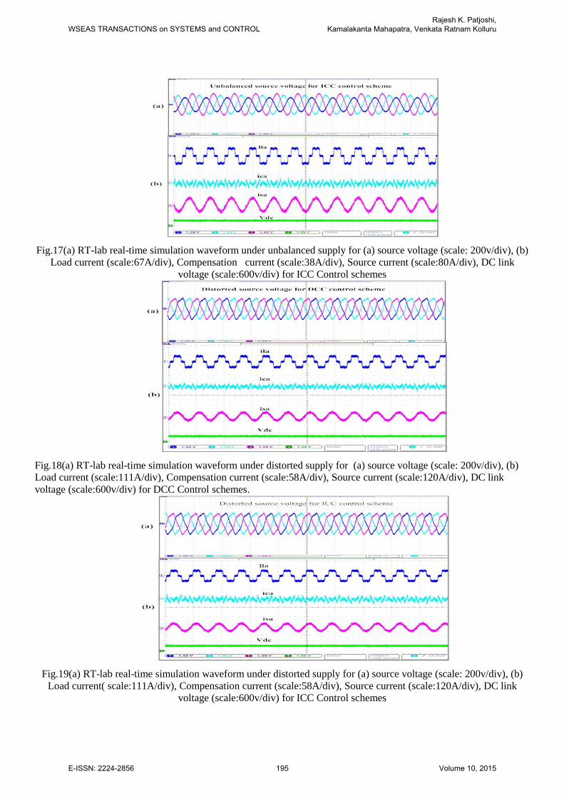
Fig.17(a) RT-lab real-time simulation waveform under unbalanced supply for (a) source voltage (scale: 200v/div), (b)
Load current (scale:67A/div), Compensation current (scale:38A/div), Source current (scale:80A/div), DC link
voltage (scale:600v/div) for ICC Control schemes
Fig.18(a) RT-lab real-time simulation waveform under distorted supply for (a) source voltage (scale: 200v/div), (b)
Load current (scale:111A/div), Compensation current (scale:58A/div), Source current (scale:120A/div), DC link
voltage (scale:600v/div) for DCC Control schemes.
Fig.19(a) RT-lab real-time simulation waveform under distorted supply for (a) source voltage (scale: 200v/div), (b)
Load current( scale:111A/div), Compensation current (scale:58A/div), Source current (scale:120A/div), DC link
voltage (scale:600v/div) for ICC Control schemes
WSEAS TRANSACTIONS on SYSTEMS and CONTROLRajesh K. Patjoshi,
Kamalakanta Mahapatra, Venkata Ratnam Kolluru
E-ISSN: 2224-2856 195 Volume 10, 2015
Fig.20 THD of Source Current for Direct sliding and Indirect sliding control strategies Using MATLAB-
SIMULINK and Real-time digital simulator
6 Conclusion
The performance of Direct and Indirect current control strategies with the various supply conditions have been presented with sliding mode based SAPF.A novel sliding mode control is employed to reduce the reference current tracking error. The main benefit of utilizing a novel sliding mode controller to the SAPF with indirect current control strategy is that it doesn't have harmonic detection component and minimizes the harmonics for the massive amount of variation of load current under non-linear load conditions. In comparison with direct current control technique, it offers a simpler system structure and better harmonic compensating performances. The simulation and Opal-RT results exhibit an excellent harmonic compensation effect with the indirect current control method over the direct current control method with consideration of all possible conditions such as balanced, unbalanced and distortions in the supply side of SAPF.
References
[1] J. Matas, L. Garcia de Vicuna, J. Miret, J. M.
Guerrero, and M. Castilla, "Feedback linearization
of a single-phase active power," IEEE Trans. on
Power Electrons, vol. 23, no. 1, p. 116–125, Mar.
2008.
[2] T. Thomas, and A. Jaffart, "Design and
performance of active power filter," IEEE Industry
Applications magazine, 1998.
[3] R. K. Patjoshi and K. K. Mahapatra, "Performance
analysis of shunt Active power filter using PLL
based control algorithms under distorted voltage
condition," in IEEE Students Conference , MNNIT
Allahabad, 2013, pp. 1-6.
[4] D. Stanciu, M. Teodorescu, A. Florescu, and D.
A. Stoichescu, "Single-phase active power filter
with improved sliding mode control," in 17th IEEE
International Conference on Automation,Quality
and Testing, Robotics (AQTR’10), May 2010, pp.
15-19.
[5] H. De Battista and R. J. Mantz, "Harmonic series
compensators in power systems: their control via
sliding mode," IEEE Trans. on Control Systems
Technology, vol. 13, no. 1, pp. 133-138, Feb. 1998.
[6] B. Singh, A. Chandra, and K. Haddad, "A new
control approach to three-phase active filter for
harmonics and reactive power compensation," IEEE
Trans.on Power Systems, vol. 13, no. 1, pp. 133-
138, Feb. 1998.
[7] S. Rahmani, K.Haddad, "Experimental design and
simulation of a modified pwm with an indirect
current control technique applied to a single-phase
shunt active power filter," IEEE International
Symposium on Industrial Electronics , vol. 2, pp.
519-524, 2005.
[8] S. Buso, L. Malesani, P. Mattavelli,
"Comparison of Current Control Techniques for
Active Filter Applications," IEEE Trans. On
Industrial Electron, vol. 45, pp. 722-729, Oct. 1998.
[9] Hu, Jiabing, et al, "Direct active and reactive power
regulation of grid-connected DC/AC converters
using sliding mode control approach," IEEE
Transactions on Power Electronics, vol. 26, no. 1,
WSEAS TRANSACTIONS on SYSTEMS and CONTROLRajesh K. Patjoshi,
Kamalakanta Mahapatra, Venkata Ratnam Kolluru
E-ISSN: 2224-2856 196 Volume 10, 2015
pp. 210-222, Jan. 2011.
[10] V. S. Bandal and P. N. Madurwa, "Performance
analysis of shunt active power filter using sliding
mode control strategies," in 12th International
workshop on Variable Structure Systems, March
2012.
[11] R. K. Patjoshi and K. K. Mahapatra, "Performance
comparison of direct and indirect current control
techniques applied to a sliding mode based shunt active
power filter," in India Conference (INDICON), 2013
Annual IEEE, IIT Bombay, Dec. 2013, pp. 1-5.
[12] Saetieo, Suttichai, Rajesh Devaraj, and David
A. Torrey, "The design and implementation of a
three-phase active power filterbased on sliding
mode control," IEEE Trans. on Industry
Applications, vol. 31, no. 5, pp. 993-1000, Sep.
1995.
[13] BHUYAN, K. C., PATJOSHI, R. K., PADHEE, S.,
and MAHAPATRA, K., "Solid Oxide Fuel Cell
with DC-DC Converter System: Control and Grid
Interfacing," WSEAS Transactions on Systems &
Control, vol. 9, 2014.
[14] ABDELKRIM, T., B, K., BENSLIMANE, T., and
BENKHELIFA, A, "Stabilization of DC Link
Voltage Using Redundant Vectors for Five-Level
Diode Clamped Shunt Active Power Filter,"
WSEAS TRANSACTIONS on CIRCUITS and
SYSTEMS, vol. 12, no. 5, pp. 151-160, May 2013.
[15] POORNASELVAN, R. S SUNDARAM K J, and
N. DEVARAJAN, "Matlab Simulation of Sliding
Mode Control of Shunt Active Filter for Power
Quality Improvement", WSEAS TRANSACTIONS
on CIRCUITS and SYSTEMS,2014.
[16] G. K. Singh, A. K. Singh, and R. Mitra, ―A simple
fuzzy logic based robust active power filter for
harmonics minimization under random load
variation,‖ Electric Power Systems Research, vol.
77, no. 8, pp. 1101–1111, 2007.
[17] Ghasemi A. ,. Mortazavi S. S.and Kianinezhad. R.,
"Fuzzy logic controlled adaptive active power filter
for harmonics minimization and reactive power
compensation under fast load variation," WSEAS
Transactions on Power Systems , vol. 3, no. 5, pp.
300-309, May 2008.
[18] AREERAK K.L.,Areerak T. N.,"Shunt Active Power
Filter Design using Genetic Algorithm Method,"
WSEA Transactions on Systems , vol. 9, no. 4, pp.
327-336, Apr. 2010.
[19] SARAVANAN P. ,BALAKRISHN P.A.,"An Efficient
BFO Algorithm for Self Tuning Pi-Controller
Parameters for Shunt Active Power Filter," WSEAS
TRANSACTIONS on Power System, vol. 9, pp. 155-
170, 2014.
[20] Moran L. A.,Fern´andez L.,Dixon J.W. and Wallace
R.,"A simple and low-cost control strategy for
active power filters connected in cascade," ndustrial
Electronics, IEEE Transactions, vol. 44, no. 5, pp.
621-629, Oct. 1997.
WSEAS TRANSACTIONS on SYSTEMS and CONTROLRajesh K. Patjoshi,