Page 1
Real-Time Manipulation with Magnetically Tunable Structures
The MIT Faculty has made this article openly available. Please share how this access benefits you. Your story matters.
Citation Zhu, Yangying, Dion S. Antao, Rong Xiao, and Evelyn N. Wang. "Real-Time Manipulation with Magnetically Tunable Structures." AdvancedMaterials, Volume 26, Issue 37, October 8, 2014, Pages: 6442–6446.
As Published http://dx.doi.org/10.1002/adma.201401515
Publisher John Wiley & Sons, Inc
Version Author's final manuscript
Citable link http://hdl.handle.net/1721.1/88536
Terms of Use Creative Commons Attribution-Noncommercial-Share Alike
Detailed Terms http://creativecommons.org/licenses/by-nc-sa/4.0/
Page 2
1
Real-Time Manipulation with Magnetically Tunable Structures
Yangying Zhu, Dion S. Antao, Rong Xiao, Evelyn N. Wang*
Department of Mechanical Engineering, Massachusetts Institute of Technology, Cambridge,
MA 02139, USA
E-mail: [email protected]
Keywords: tunable surface, dynamic material, magnetic, real-time manipulation, directional
wettability
Responsive actuating surfaces have attracted significant attention as promising materials for
liquid transport in microfluidics, cell manipulation in biological systems, and light tuning in
optical applications via their dynamic regulation capability. Significant efforts have focused
on fabricating static micro and nanostructured surfaces,[1,2,3,4,5]
even with asymmetric features
to realize passive functionalities such as directional wettability[6,7]
and adhesion.[8,9]
Only
recent advances in utilizing materials that mechanically respond to thermal,[10,11,12,13]
chemical[14,15,16,17]
or magnetic[18,19,20,21,22,23]
stimuli have enabled dynamic regulation.
However the challenges with these surface designs are associated with the tuning range,[19,20]
accuracy,[19,20,21,22,23]
response time[10,11,12,13,15,16,17]
and multi-functionality for advanced
systems. Here we report dynamically tunable micropillar arrays with uniform, reversible,
continuous and extreme tilt angles with precise control for real-time fluid and optical
manipulation. Inspired by hair and motile cilia on animal skin and plant leaves for
locomotion,[24]
liquid transportation[25]
and thermal-optical regulation,[26,27]
our flexible
uniform responsive microstructures (µFUR) consist of a passive thin elastic skin and active
ferromagnetic microhair whose orientation is controlled by a magnetic field. We
experimentally show uniform tilt angles ranging from 0° to 57°, and developed a model to
accurately capture the tilting behavior. Furthermore, we demonstrate that the µFUR can
control and change liquid spreading direction on demand, manipulate fluid drag, and tune
optical transmittance over a large range. The versatile surface developed in this work enables
Page 3
2
new opportunities for real-time fluid control, cell manipulation, drag reduction and optical
tuning in a variety of important engineering systems, including applications that require
manipulation of both fluid and optical functions.
Dynamically tunable structured surfaces offer new manipulation capabilities in mechanical,
fluidic, and optical systems. Examples from nature have inspired the design of such active
systems: bacteria use flagella as propellers[24]
and motile cilia in the lining of human
respiratory airways move mucus and dirt out of the lungs.[25]
These biological systems display
well-defined structural patterns and controllable mechanical motion in response to different
stimuli. Accordingly, researchers have investigated various approaches to fabricate tunable
microstructures including temperature-sensitive liquid crystalline[13]
and thermoplastic
elastomers,[10]
hydrogels that respond to thermal, chemical or optical stimuli,[11,12,14,15,16,17]
and
polymer-based magnetically actuated structures[18,19,20,21,22,23]
over the past decade. However,
the response of the thermally actuated elastomer is either irreversible[10]
or slow[13]
and the
hydrogels require a liquid environment and have a long response time, thus limiting their
applications.
Magnetically actuated surfaces, on the other hand, are attractive due to their instantaneous
response and the non-intrusive nature of magnetic fields. Many of the reported approaches use
magnetic particles mixed with or encapsulated by soft materials to form microstructures that
deflect in an external magnetic field.[18,19,20,21,22,23]
These composite surfaces have been used
to apply forces to living cells for different cellular reactions,[19]
generate rotational and
translational fluid movements in microfluidics,[20,21]
as well as manipulate and mix
droplets.[22]
However due to their low magnetic strength which is limited by the volume
fraction of particles in the polymer matrix, the tilt angles were usually small and
Page 4
3
non-uniform.[19,20,21]
Thus, the tuning capability has generally been limited to on-off control,
as opposed to a continuous tuning range which is more desirable. Recently a large tuning
range of these composite micropillars has been realized by higher and a more uniform
distribution of stronger magnetic particles in the polymer matrix.[23]
The surface was used to
demonstrate switchable adhesive properties.
Here we present a hybrid approach for the development of flexible uniform responsive
microstructures (µFUR, Figure 1a) in which a thin elastic polydimethylsiloxane (PDMS)
layer serves as the skin and a ferromagnetic micropillar array functions as the tunable hair
(Figure 1b). The uniform volumetric properties of the pillars allow high fidelity modeling and
uniform tilt angle control. Furthermore, the μFUR completely decouples the mechanical,
magnetic, wettability and optical properties of the micropillars and the substrate by the use of
the two distinct materials, which expands the functionality where different surface properties
are required (Figure 1c). With this design, we demonstrated uniform and continuous tilt
angles (Figure 1d, Supporting Information Video 1 and 2) which were captured accurately by
our model. In the extreme case where the pillars are in contact with the adjacent ones, the tilt
angle reaches a maximum of 57° (Figure 1e). This maximum tilt angle can be further
increased by optimizing the pillar spacing. We show that µFUR is capable of real-time
manipulation of liquid spreading directionality, fluid drag, and optical transmittance.
Page 5
4
Figure 1. a) The fabricated flexible uniform responsive microstructures (µFUR). The dark
region is the micropillar array and the transparent substrate is the PDMS skin. Scale bar is 5
mm. b) Schematic showing the concept of µFUR where the tilt angle can be controlled via an
external magnetic field. θ is the micropillar tilt angle and α is the magnetic field angle. c)
Schematic of potential applications including microfluidic and optical manipulation. Side
view images of the fabricated µFUR with an applied magnetic field strength of 0.5 T and field
angle of d) α = 60° and e) α = 95° respectively. Scale bars are 50 µm.
The surfaces were created by fabricating ferromagnetic micropillars and then bonding to a
soft PDMS substrate as summarized in Figure 2a. A dense array of nickel pillars with
diameters (d) of 26-30 µm, heights (h) of 70-75 µm, and spacings (l) of 60 µm was
electroplated (Figure 2b – 2d). The geometries were chosen due to the ease of fabrication. The
nickel posts were subsequently bonded to a PDMS surface through a silica adhesion layer
(Figure 2e). The fabrication of µFUR was demonstrated repeatably over an area of
8 mm × 8 mm and can be easily scaled to larger arrays.
Page 6
5
Figure 2. a) Fabrication process flow. First, photoresist was patterned on a gold (Au) seed
layer and a titanium (Ti) adhesion layer e-beam evaporated on a silicon (Si) substrate; Second,
nickel (Ni) was electroplated inside the photoresist mold and then the photoresist was
stripped; Third, the nickel pillars were bonded to PDMS through a silica adhesion layer;
Finally, the silicon substrate was detached from the pillars. b) Optical microscope image of
the nickel pillar arrays on silicon. c) and d) SEMs of the nickel pillar arrays on silicon. e)
SEM of the nickel pillar arrays bonded to PDMS. Scale bars are 100 μm. f) Finite element
simulation (Abaqus) results of the reaction torque as a function of the tilt angle when
h = 80 μm and d = 26 μm. The solid line is from the simulation and the dotted line is the
linear fit. The inset provides a schematic of the torques exerted on the pillars. g) Calculation
and experimental results of tilt angle as a function of field strength and field angle. Error bars
Page 7
6
account for the standard deviation of multiple measurements (on 30 pillars) and an estimated
system error.
With the fabricated pillar geometry and magnetic properties (see Supporting Information
Figure S1), we developed a model to predict the equilibrium micropillar tilt angle θ under
various magnetic field conditions. The model is based on the balance of a magnetic torque
generated by an external magnetic field (see Supporting Information and Figure S2) and a
corresponding reaction torque from the constraint of the PDMS substrate (inset of Figure 2f).
The reaction torque was obtained from finite element simulations (Abaqus), which show a
linear relation between the reaction torque and the micropillar tilt angle θ (Figure 2f and
Figure S3). Figure 2g shows that θ increases with both the magnetic field strength and field
angle α. To measure the tilt angle of the fabricated µFUR, we applied the magnetic field using
two parallel neodymium disc magnets (see Experimental Section and Figure S4). The
magnetic field strength and field angle were determined by the orientation, diameter,
thickness and spacing of the magnets. The experimental data shown in Figure 2g were taken
when the magnetic field was kept at constant strength and field angles. The equilibrium tilt
angle θ was obtained by side view microscope images of the pillar arrays (Figure 1d and 1e).
The tilt angle response of the micropillars to a field angle change was instantaneous and no
apparent hysteresis was observed over multiple measurement cycles due to the small
hysteresis in the magnetization shown in Figure S1. Our experimental results are in excellent
agreement with the model (Figure 2g), which demonstrates our ability to accurately control
the micropillar tilt angle with an external field.
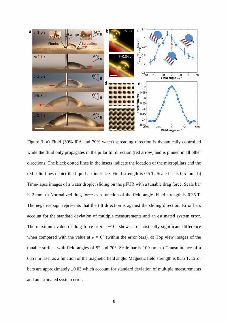
We show the versatility of our µFUR to dynamically manipulate liquid spreading, control
fluid drag and tune optical transmittance. First, we demonstrate that we can achieve real-time
Page 8
7
liquid directional spreading by dynamically changing the pillar tilt orientation and angle,
where past studies have only shown uni-directional wetting in a fixed direction on static
asymmetric structures.[6,7]
We introduced a wetting liquid (30% IPA and 70% water), which
satisfies the imbibition condition[28]
to the surface through a syringe at a constant flow rate of
0.25 µL s-1
(Figure 3a and Supporting Information Video 3). The liquid film propagates only
if the contact line is able to reach the next row of the pillars (inset of Figure 3a). Therefore,
under the magnetic field, the asymmetric structures can initiate a preferential propagation
direction (Figure S5), which is determined by the micropillar tilt angle, spacing and the
intrinsic contact angle of the liquid on the surface.[6]
The surface was initially subjected to a
magnetic field tilted to the right (α = 60°, µ0H = 0.5 T) and the fluid only flowed in the pillar
tilt direction while being highly pinned in all other directions. At t = 2.5 s and t = 6.2 s, the
direction of the magnetic field was switched. As a result the fluid instantaneously changed its
propagating and pinning directions (Supporting Information Video 3). This dynamic
manipulation can be achieved when the pillar tilt angle θ is above 12° for the test fluid (30%
IPA and 70% water) which is determined by the pillar geometry and surface wettability, and
agrees with a model developed by Chu et al. for static asymmetric structures.[6]
Furthermore,
this repeatable and instantaneous manipulation capability is not restricted to the ± x direction,
but can be applied to all directions on the 2D surface, and even on a vertically inclined surface
(Supporting Information Video 4).
Page 9
8
Figure 3. a) Fluid (30% IPA and 70% water) spreading direction is dynamically controlled
while the fluid only propagates in the pillar tilt direction (red arrow) and is pinned in all other
directions. The black dotted lines in the insets indicate the location of the micropillars and the
red solid lines depict the liquid-air interface. Field strength is 0.5 T. Scale bar is 0.5 mm. b)
Time-lapse images of a water droplet sliding on the μFUR with a tunable drag force. Scale bar
is 2 mm. c) Normalized drag force as a function of the field angle. Field strength is 0.35 T.
The negative sign represents that the tilt direction is against the sliding direction. Error bars
account for the standard deviation of multiple measurements and an estimated system error.
The maximum value of drag force at α = −10° shows no statistically significant difference
when compared with the value at α = 0° (within the error bars). d) Top view images of the
tunable surface with field angles of 5° and 70°. Scale bar is 100 µm. e) Transmittance of a
635 nm laser as a function of the magnetic field angle. Magnetic field strength is 0.35 T. Error
bars are approximately ±0.03 which account for standard deviation of multiple measurements
and an estimated system error.
Page 10
9
We also show that µFUR can tune the drag force with high surface tension fluids, e.g., water.
Past works have focused on reducing fluid drag with static hydrophobic microstructures.[29,30]
In contrast, increasing the tilt angle of the µFUR decreases the effective fluid-surface contact
area (solid fraction), and changes the fluid-solid interface morphology. We examined the
sliding behavior of a water droplet (7 µL) on a tilted surface under various field angles
(Figure 3b) at 0.35 T, the velocity and acceleration of which were extracted from the time-
lapse images captured by a high-speed camera to obtain the drag force.
From the displacement data, e.g., in Figure S6, the droplet experiences a short acceleration
period after detaching from the needle, and then transitions to a steady deceleration mode due
to the drag force. The acceleration originates from the deformation of the droplet shape which
lowers its potential energy and is converted to kinetic energy. A second order polynomial
relation between the displacement x and time t was observed for the deceleration mode,
indicating a constant drag force for each situation, i.e., a = d2x/dt
2. The drag force, Fdrag, is
then determined based on a force balance,
sin( ) dragma mg F (1)
where β is the slope angle (40°) and m is the mass of the droplet. We normalized the drag
force with respect to the zero field angle case (α = 0°) to facilitate a comparison. A maximum
reduction in drag of 28% was observed at a field angle of −50° (Figure 3c and Supporting
Information Video 5). The drag force decreases with an increase in tilt angle both against the
flow and with the flow due to the effect of reduced solid fraction. The solid fraction at zero
field angle can be changed by altering the geometry of the µFUR during fabrication. This,
however, will only change the absolute drag force exerted on the droplet, where the relative
trends with the dynamic tunability will remain the same.
Page 11
10
The difference in the optical properties between the opaque pillar surface and the transparent
PDMS film provides additional opportunities for dynamic optical tuning. This is typically
difficult to achieve using hydrogel structures or PDMS structures mixed with magnetic
particles because the refractive indices of the hydrogel and the surrounding liquid are similar,
and usually both the substrate and the micropillars of the PDMS/magnetic particle mixtures
have the same optical properties.[20,21]
We demonstrated that by utilizing the asymmetry of the
microstructures (Figure 3d and Supporting Information Video 2), the surface can function
similar to ‘window blinds’, where the transmittance can be tuned on demand. We measured
the transmitted power of a collimated laser beam (λ = 635 nm, spot size was 1.5 – 2 mm)
through the sample using a photodiode detector (Figure S8 and Experimental Section). The
transmittance of μFUR was calculated using the detected power of the laser beam through the
sample and the glass normalized by that through the glass only. Transmittance of the μFUR
ranging from 0.38 to 0.71 under different magnetic field angles at 0.35 T was observed
(Figure 3e). The response is instantaneous and the results were repeatable. This work suggests
that the surface has great potential in applications where manipulating both liquid and light is
required.
We have demonstrated a tunable and controlled platform using simple fabrication approach,
which has a large tuning range (0 - 57° tilt angles) with precise and continuous control. The
versatile µFUR is capable of dynamic manipulation of fluid spreading directionality, fluid
drag, and can tune optical transmittance over a large range by adjusting the applied magnetic
field. This work provides exciting opportunities for real-time fluid and light manipulation.
Biomimetic functionalities such as locomotion and liquid or cell transport can potentially be
achieved by applying localized and variable magnetic fields. It will also be of significant
interest as the size of the micropillars is scaled down to the order of the wavelength of visible
Page 12
11
light, when the structures can coherently manipulate light propagation and act as tunable
photonic crystals. By tuning the geometry, wettability, optical properties and surface
chemistry of the micropillars and the substrate, the surface can expand its manipulation
capabilities, and serve as an important platform for applications such as smart window,
versatile artificial skin, cell manipulation, dynamic optical devices and fluid control. In
applications with high curvature and complex shaped substrates, a modified distribution of the
magnetic field may be applied to achieve the desired tilt angle.
Experimental Section
Tilt Angle Measurement: The experimental setup to measure the tilt angle is illustrated in
Figure S4. An optical microscope was used to capture the side view images of the pillar arrays.
The µFUR is attached to a glass slide, which is inserted into a cylindrical Teflon sample
holder. To provide an external magnetic field, the sample was placed between two
neodymium disc magnets (Grade N52, K&J Magnetics, Inc.) which were placed parallel to
each other on the two arms of a steel clevis. The clevis was inserted into a ball bearing so that
the attached magnets could be rotated around the sample surface while maintaining a constant
field strength during rotation. The magnetic field orientation was controlled by rotating the
clevis, and the magnetic field strength was calculated by K&J Magnetics Gap Calculator
(K&J Magnetics) based on the diameter, thickness and gap. Tilt angles in magnetic field of
0.35 T and 0.5 T were measured as a function of field angles.
Drag Force Measurement: To measure the drag force, we examined the sliding behavior of a
water drop (7 µL) on a tilted μFUR surface (40°) under various field angles and a field
strength of 0.35 T. The initial condition was kept the same for all of the experiments. DI water
supplied by a syringe at a fixed flow rate of approximately 2.5 µL s-1
was used as the test fluid.
Page 13
12
The distance between the syringe needle and the tunable surface was adjusted such that the
droplet just touched the surface when it detached from the needle. High-speed camera
imaging (Phantom v7.1, Vision Research) at 500 frames s-1
was used to capture the droplet
displacement x as a function of time t (Figure S6 and S7).
Transmittance Measurement: The experimental setup to measure transmittance is illustrated
in Figure S8. Two mirrors at an angle of 90° were attached to the sample holder with one 45°
above the horizontal and the other 45° below the horizontal. The tunable surface sample was
placed on a horizontal glass slide between the two mirrors. A laser with a 635 nm wavelength
(LTG6351AH, Lasermate Group, Inc.) was used as the light source for the measurement. The
laser had an elliptical beam profile (3.3 mm × 3.6 mm), and was well-collimated with a beam
divergence of less than 0.5 mrad. An iris (ID-1.0, Newport) was used to define a circular spot
shape of the laser beam. The beam diameter of the laser after the iris was 1.5 - 2 mm. The
laser was adjusted such that the beam was horizontal and transmitted through the tunable
surface as indicated by Figure S8. The distance between the laser source and the sample was
approximately 13 cm. A third mirror was used to reflect the transmitted laser beam to a
photodiode detector (818UV, Newport) connected to a power meter (1918C, Newport). The
transmittance of μFUR was calculated using the detected power of the laser beam through the
sample and the glass substrate normalized by that through the glass only. The measured
transmittance through the fabricated PDMS substrate was 0.91 ±0.03.
Acknowledgements
We thank D. Kim and C. Ross for use of VSM equipment; K. Wang and T. Wierzbicki for
help with Abaqus simulation; J. Tong for use of laser equipment; K.-H. Chu, Y. Nam, Y.
Yang and P. Kim for discussion. We gratefully acknowledge funding support from the Air
Force Office of Scientific Research (AFOSR, Grant FA9550-11-1-0059). We would also like
to acknowledge the MIT Microsystems Technology Lab for fabrication staff support, help,
and use of equipment.
Page 14
13
[1] E. Martines, K. Seunarine, H. Morgan, N. Gadegaard, C. D. W. Wilkinson, M. O.
Riehle, Nano Lett. 2005, 5, 2097.
[2] L. Qu, L. Dai, M. Stone, Z. Xia, Z. L. Wang, Science 2008, 322, 238.
[3] K.-C. Park, H. J. Choi, C.-H. Chang, R. E. Cohen, G. H. McKinley, G. Barbastathis,
ACS Nano 2012, 6, 3789.
[4] F. Priolo, T. Gregorkiewicz, M. Galli, T. F. Krauss, Nat. Nanotechnol. 2014, 9, 19.
[5] A. Lenert, D. M. Bierman, Y. Nam, W. R. Chan, I. Celanović, M. Soljačić, E. N.
Wang, Nat. Nanotechnol. 2014, doi:10.1038/nnano.2013.286.
[6] K.-H. Chu, R. Xiao E. N. Wang, Nat. Mater. 2010, 9, 413.
[7] N. A. Malvadkar, M. J. Hancock, K. Sekeroglu, W. J. Dressick, M. C. Demirel, Nat.
Mater. 2010, 9, 1023.
[8] H. E. Jeong, M. K. Kwak, K. Y. Suh, Langmuir 2010, 26, 2223.
[9] D. Santos, S. Kim, M. Spenko, A. Parness, M. Cutkosky, in 2007 IEEE Int. Conf.
Robot. Autom. 2007, 1262, doi:10.1109/ROBOT.2007.363158.
[10] S. Reddy, E. Arzt, A. del Campo, Adv. Mater. 2007, 19, 3833.
[11] R. Yoshida, K. Uchida, Y. Kaneko, K. Sakai, A. Kikuchi, Y. Sakurai, T. Okano,
Nature 1995, 374, 240.
[12] X. He, M. Aizenberg, O. Kuksenok, L. D. Zarzar, A. Shastri, A. C. Balazs, J.
Aizenberg, Nature 2012, 487, 214.
[13] J. Cui, D.-M. Drotlef, I. Larraza, J. P. Fernández-Blázquez, L. F. Boesel, C. Ohm, M.
Mezger, R. Zentel, A. del Campo, Adv. Mater. 2012, 24, 4601.
[14] L. D. Zarzar, P. Kim, J. Aizenberg, Adv. Mater. 2011, 23, 1442.
[15] T. Tanaka, D. Fillmore, S.-T. Sun, I. Nishio, G. Swislow, A. Shah, Phys. Rev. Lett.
1980, 45, 1636.
Page 15
14
[16] D. J. Beebe, J. S. Moore, J. M. Bauer, Q. Yu, R. H. Liu, C. Devadoss B.-H. Jo, Nature
2000, 404, 588.
[17] P. J. Glazer, J. Leuven, H. An, S. G. Lemay, E. Mendes, Adv. Funct. Mater. 2013, 23,
2964.
[18] J. Kim, S. E. Chung, S.-E. Choi, H. Lee, J Kim, S. K. Kim, Nat. Mater. 2011, 10, 747.
[19] N. J. Sniadecki, A. Anguelouch, M. T. Yang, C. M. Lamb, Z. Liu, S. B. Kirschner, Y.
Liu, D. H. Reich, C. S. Chen, Proc. Natl. Acad. Sci. 2007, 104, 14553.
[20] A. R. Shields, B. L. Fiser, B. A. Evans, M. R. Falvo, S. Washburn, R. Superfine, Proc.
Natl. Acad. Sci. 2010, 107, 15670.
[21] F. Fahrni, M. W. J. Prins, L. J. van IJzendoorn, Lab. Chip 2009, 9, 3413.
[22] J. V. I. Timonen, C. Johans, K. Kontturi, A. Walther, O. Ikkala, R. H. A. Ras, ACS
Appl. Mater. Interfaces. 2010, 2, 2226.
[23] D.-M. Drotlef, P. Blümler, A. del Campo, Adv. Mater. 2014, 26, 775.
[24] R. M. Macnab, J. Bacteriol. 1999, 181, 7149.
[25] Y. Enuka, I. Hanukoglu, O. Edelheit, H. Vaknine, A. Hanukoglu, Histochem. Cell Biol.
2012, 137, 339.
[26] N. C. Turner, P. J. Kramer, Adaptation of Plants to Water and High Temperature
Stress, J. Wiley, 1980.
[27] P. F. Scholander, V. Walters, R. Hock, L. Irving, Biol. Bull. 1950, 99, 225.
[28] J. Bico, C. Tordeux, D. Quéré, EPL Europhys. Lett. 2001, 55, 214.
[29] F. Shi, Z. Wang, X. Zhang, Adv. Mater. 2005, 17, 1005.
[30] W. Barthlott, T. Schimmel, S. Wiersch, K. Koch, M. Brede, M. Barczewski, S.
Walheim, A. Weis, A. Kaltenmaier, A. Leder, H. F. Bohn, Adv. Mater. 2010, 22, 2325.
Page 16
15
Supporting Information
Real-Time Manipulation with Magnetically Tunable Structures
Yangying Zhu, Dion S. Antao, Rong Xiao, Evelyn N. Wang*
Sample Fabrication
A 100 nm gold layer was deposited on top of a 20 nm titanium adhesion layer as the main
seed layer on a 6 inch silicon substrate by e-beam thermal evaporation. A 100 µm thick
negative photoresist (KMPR 1050, MicroChem) layer was spin-coated on the seed layer at
1300 rpm for 30 s, soft baked on a hotplate at 100 °C for 27 min, exposed to UV illumination
at 750 mJ cm-2
, post baked at 100 °C for 6 min and developed for 15 min. The result was a
thick photoresist layer with uniform hole arrays. The wafer was then diced into 2×2 cm2
samples. To remove air trapped in the hole arrays of the photoresist, the sample was treated
with oxygen plasma (29 W at 500 mTorr for 30 min) and sonicated in the plating solution for
45 s. A dense array of nickel pillars was subsequently obtained by electroplating (Nickel
Sulfamate RTU, Technic Inc.) at 50 °C for 6 hours with a current density of 13 mA cm-2
. The
patterned photoresist surface was lifted by immersing in acetone (room temperature, 8 hours)
and in MicroChem Remover PG (70 °C, 2 hours). Photoresist residue was oxidized by sodium
permanganate and dissolved in methane sulfonic acid. The sample was rinsed with DI water.
A ~10 nm silica layer was deposited on the pillar tips by plasma-enhanced chemical vapor
deposition (PECVD). A 100 µm PDMS layer was spin-coated on a glass substrate, cured, and
oxygen plasma treated (29 W at 500 mTorr for 10 min). The nickel pillars coated with silica
on the tips were subjected to the same plasma treatment conditions and bonded onto the
PDMS surface. The sample was immersed in a nickel compatible gold etchant (Sigma-
Aldrich) and degased. The solution was then heated to 70 °C on a hotplate for 2 hours to etch
away the gold seed layer such that the pillars (detached from the silicon substrate) remained
Page 17
16
only on the PDMS substrate.
Magnetic Properties of Electroplated Nickel
After the photoresist removal, we characterized the magnetic properties of the pillar arrays
using vibrating sample magnetometer (VSM), and confirmed that they match the properties of
bulk nickel with a coercivity of 60 Oe (4.8×10³ A m
-1). The measured magnetization M is
normalized with respect to the saturation value (Msat = 0.6 T for nickel). Magnetization
saturates at an applied magnetic field strength of 0.3 T (Figure S1). The measured
magnetization is used in the model to calculate the magnetic torque and to calculate the tilt
angle θ.
Model
The model consists of 80 µm nickel pillars attached to a layer of 100 µm soft PDMS layer
with the fabricated pillar geometry and magnetic properties, where the bottom surface of the
PDMS layer was fixed. The magnetic torque is given by Equation S1,
magT V M B (S1)
where V is the volume of the magnetic pillar, M is the magnetization of the nickel
micropillars which is assumed to be in the axial direction, and B is the magnetic flux density.
Considering the pillar geometry, applied field strength and field angle, the magnetic torque
can be calculated as,
2
0 sin( )4
magT d hM H
(S2)
where d and h are the diameter and height of the pillars, M is the magnitude of magnetization,
µ0 is the vacuum permeability, H is the magnitude of the applied field, α is the field angle
Page 18
17
defined as the angle between the applied field and the surface vertical direction, and θ is the
pillar tilt angle. Figure S2 shows the magnetic torque as a function of the tilt angle θ
according to Equation S2. Tmag increases with the magnetic field strength and field angle.
The relationship between the reaction torque and the tilt angle was obtained using finite
element simulations (Abaqus). The model consists of a 100 µm thick PDMS substrate with
the bottom surface fixed. Five pillars were built in the model and we assume that the periodic
boundary conditions are valid for the pillar in the center. The nickel pillars (heights h = 80 µm,
diameters d = 26 µm, spacings l = 60 µm) were adhered to the PDMS layer with 60 µm above
the PDMS surface and 20 µm embedded in the PDMS layer. Contact surfaces between the
PDMS and the pillars were tied together. A torque was applied on each micropillar
(clockwise). All other surfaces are free surfaces. An equilibrium tilt angle of the pillar in the
center was captured by the model under each applied torque ranging from 0 N·m to
3.5×10⁻⁹
N·m (Figure 2f). Figure S3 shows an example of the model when the applied torque
is 3.5×10⁻⁹
N·m. The reaction torque Treaction from the PDMS has the same magnitude as the
applied torque at equilibrium.
The tilt angle θ of the micropillars under an applied magnetic field was calculated by solving
Equation S3, which is a torque balance equation between the magnetic torque and the reaction
torque.
( , , ) ( )mag reactionT H T (S3)
The final result can be expressed as θ = f (H, α), as shown in Figure 2g.
Drag Force Calculation
To compare the effect of the magnetic field angle α on the drag force, we normalized Fdrag as
Page 19
18
shown in Equation S4,
( ) sin( ) ( )
( 0 ) sin( ) ( 0 )
drag
drag
F g a
F g a
(S4)
where β is the slope angle. Figure S7 and Supporting Information Video 5 show a higher
deceleration at α = −20° than α = −50°, indicating a higher drag force at α = −20°. When α =
−50°, the displacement is approximately linear with time, indicating a reduced drag force
close to mg·sin(β).
Page 20
19
Supporting Information Figures
Figure S1 Normalized magnetization of the electroplated nickel pillar arrays measured by
vibrating sample magnetometer. The magnetization is normalized with respect to the
saturation magnetization (Msat = 0.6 T for nickel). The measured magnetization is used in the
model to calculate the magnetic torque given by Equation S2 and to calculate the tilt angle θ.
Page 21
20
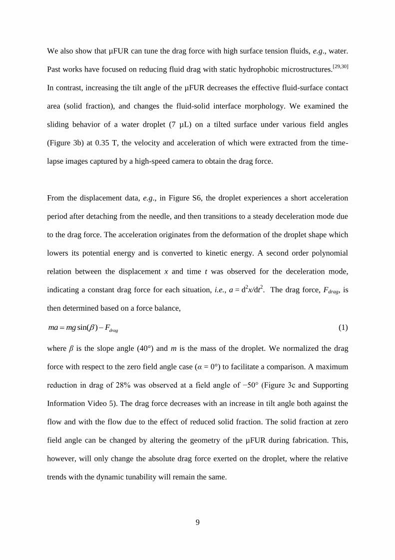
Figure S2 Magnetic torque as a function of tilt angle under different a) magnetic field angles
and b) field strength based on Equation S2. Magnetic torque increases with both magnetic
field angle and field strength.
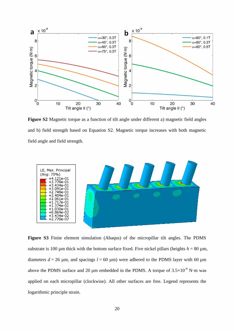
Figure S3 Finite element simulation (Abaqus) of the micropillar tilt angles. The PDMS
substrate is 100 µm thick with the bottom surface fixed. Five nickel pillars (heights h = 80 µm,
diameters d = 26 µm, and spacings l = 60 µm) were adhered to the PDMS layer with 60 µm
above the PDMS surface and 20 µm embedded in the PDMS. A torque of 3.5×10⁻⁹
N·m was
applied on each micropillar (clockwise). All other surfaces are free. Legend represents the
logarithmic principle strain.
Page 22
21
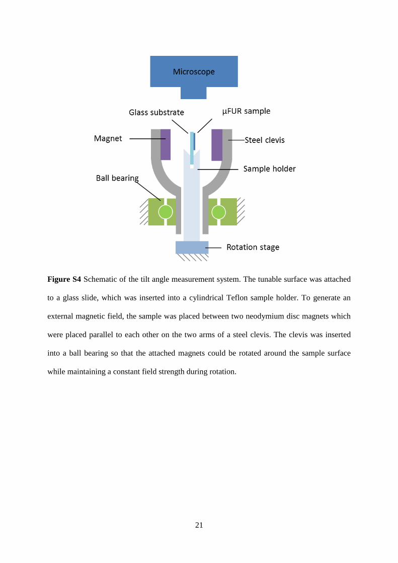
Figure S4 Schematic of the tilt angle measurement system. The tunable surface was attached
to a glass slide, which was inserted into a cylindrical Teflon sample holder. To generate an
external magnetic field, the sample was placed between two neodymium disc magnets which
were placed parallel to each other on the two arms of a steel clevis. The clevis was inserted
into a ball bearing so that the attached magnets could be rotated around the sample surface
while maintaining a constant field strength during rotation.
Page 23
22
Figure S5 Time-lapse images of a fluid (30% IPA and 70% water) spreading on µFUR under
two different magnetic field directions. The magnetic field strength is 0.5 T. a) Magnetic field
angle is 60°. The fluid spreads to the right and is pinned in all other directions. b) Magnetic
field angle is 0°. The fluid spreads in all directions. Scale bar is 0.5 mm.
Page 24
23
Figure S6 Time-lapse high-speed camera images of a water droplet sliding on μFUR (tilted at
40°) under a magnetic field of 0.35 T at two different field angles. a) Magnetic field angle is
−20°. b) Magnetic field angle is -50°. Droplet position x can be extracted as a function of time
t. The displacements indicate a reduced drag force at α = -50° compared to α = -20°. Scale
bars are 2 mm.
Page 25
24
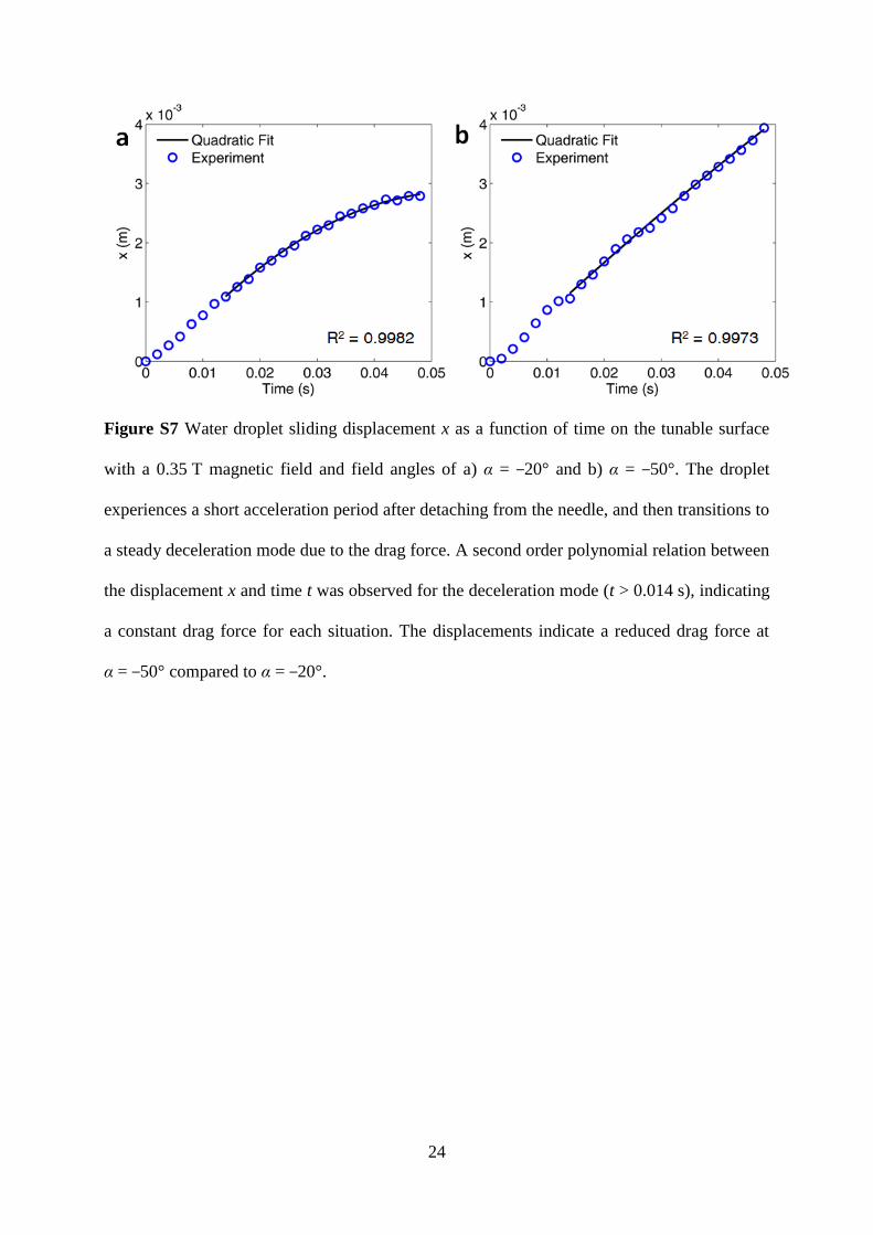
Figure S7 Water droplet sliding displacement x as a function of time on the tunable surface
with a 0.35 T magnetic field and field angles of a) α = −20° and b) α = −50°. The droplet
experiences a short acceleration period after detaching from the needle, and then transitions to
a steady deceleration mode due to the drag force. A second order polynomial relation between
the displacement x and time t was observed for the deceleration mode (t > 0.014 s), indicating
a constant drag force for each situation. The displacements indicate a reduced drag force at
α = −50° compared to α = −20°.
Page 26
25
Figure S8 Schematic of transmittance measurement system. Two mirrors at an angle of 90°
were attached to the sample holder with one 45° above the horizontal and the other 45° below
the horizontal. The tunable surface sample was placed on a horizontal glass slide between the
two mirrors. A laser with 635 nm wavelength (LTG6351AH, Lasermate Group, Inc.) was
used as the light source for the measurement. The laser was adjusted such that the beam was
horizontal and transmitted through the tunable surface. A photodiode detector (818UV,
Newport) connected to a power meter (1918C, Newport) was used to measure the transmitted
power.