8
G A-A22705 REAL-TIME PROTECTION OF THE OHMIC HEATING COIL FORCE LIMITS IN DIN-D by J.D. BROESCH, J.T. SCOVILLE, A.W. HYATT, R.M. COON NOVEMBER 1997 19980420 067 GENEHL ATOMICS

G A-A22705
REAL-TIME PROTECTION OF THE OHMIC HEATING COIL FORCE LIMITS IN DIN-D
by J.D. BROESCH, J.T. SCOVILLE, A.W. HYATT, R.M. COON
NOVEMBER 1997
19980420 067 GENEHL ATOMICS

G A-A22705
REALITIME PROTECTION OF THE OHMIC HEATING COIL FORCE LIMITS IN DIII-D
by J.D. BROESCH, J.T. SCOVILLE, A.W. HYA'TT, R.M. COON
This is a preprint of a paper to be presented at the 10th IEEE Real Time Conference 1997, September 22-26, 1997, Beaune, France and to be published in the Proceedings.
Work supported by the U.S. Department of Energy
under Contract No. DE-AC03-89ER51114
GA PROJECT 3466 NOVEMBER 1997
GENERAL ATOMICS
1 J.D. Broesch et al. Real-Time Protection of the Ohmic Heating Coil Force Limits in DIII-D
Real-Time Protection of the Ohmic Heating Coil Force Limits in DIII-D
J.D. Broesch, J.T. Scoville, A.W. Hyatt, R.M. Coon General Atomics, P.O. Box 85608, San Diego, California 92186-5608
Abstract The maximum safe operating limits of the DIII-D toka-
mak are determined by the force produced in the ohmic heating coil and the toroidal field coil during a plasma pulse. This force is directly proportional to the product of the current in the coils. Historically, the current limits for each coil were set statically before each pulse without regard for the time varying nature of the currents. In order to allow the full time-dependent capability of the ohmic coil to be used, a system was devel- oped for monitoring the product of the currents dynamically and making appropriate adjustments in real time. This paper discusses the purpose, implementation, and results of this work.
BACKGROUND During 1996 operations, a failure in one of the two ohmic
heating solenoids occurred. This failure resulted from fatigue due to the force produced by the current carrying ohmic coil lead passing through the toroidal field. The reduced capability of the ohmic heating coil, and the desire to maximize its per- formance, have dictated developing a new procedure for con- trolling the forces due to the coil currents.
The ohmic heating coil lead is being repaired. Delivering optimum performance from the good solenoid while this work is undertaken necessitates ramping the ohmic field while the toroidal field is ramping. This technique is of general interest, however, as it will continue to yield improved performance even after the lead has been repaired and the second ohmic coil solenoid has been returned to service.
The new technique involves two major changes: increas- ing the ohmic coil current to a higher level than previously authorized, and the simultaneous ramping of the ohmic heat- ing coil with the ramping of the toroidal field coil. The real- time monitoring techniques for insuring that this increased ohmic heating coil current does not lead to damage are the focus of this paper. To put the solution into proper context, we will first briefly describe the operation of the relevant systems.
I. SYSTEM DESCRIPTION A cross sectional view of the DIII-D tokamak is shown
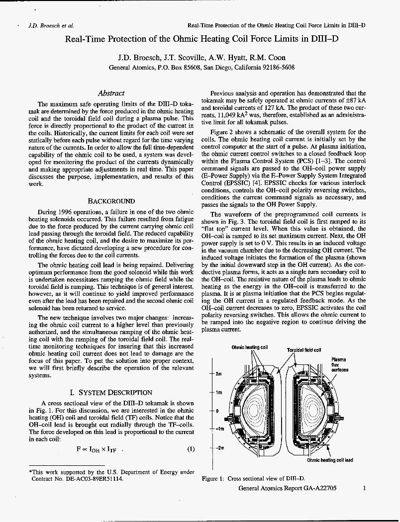
in Fig. 1. For this discussion, we are interested in the ohmic heating (OH) coil and toroidal field (W) coils. Notice that the OH-coil lead is brought out radially through the TF-coils. The force developed on this lead is proportional to the current in each coil:
F x 1 0 ~ x 1 ~ ~ . (1)
*This work supported by the U.S. Department of Energy under Contract No. DE-AC03-89ER51114.
Previous analysis and operation has demonstrated that the tokamak may be safely operated at ohmic currents of +87 kA and toroidal currents of 127 kA. The product of these two cur- rents, 11,049 kA2 was, therefore, established as an administra- tive limit for all tokamak pulses.
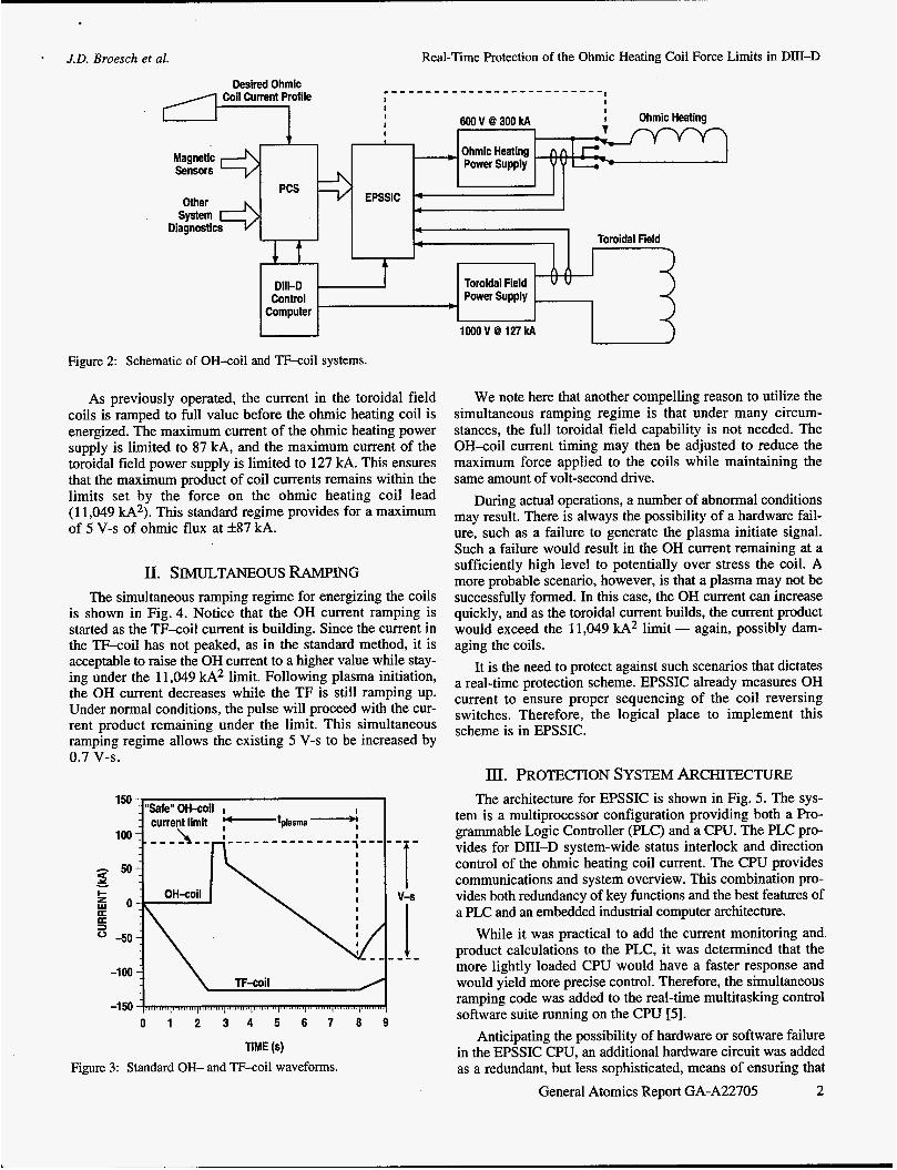
Figure 2 shows a schematic of the overall system for the coils. The ohmic heating coil current is initially set by the control computer at the start of a pulse. At plasma initiation, the ohmic current control switches to a closed feedback loop within the Plasma Control System (PCS) [l-31. The control command signals are passed to the OH-coil power supply (E-Power Supply) via the E-Power Supply System Integrated Control (EPSSIC) [4]; EPSSIC checks for various interlock conditions, controls the OH-coil polarity reversing switches, conditions the current command signals as necessary, and passes the signals to the OH Power Supply.
The waveform of the preprogrammed coil currents is shown in Fig. 3. The toroidal field coil is first ramped to its “flat top” current level. When this value is obtained, the OH-coil is ramped to its set maximum current. Next, the OH power supply is set to 0 V. This results in an induced voltage in the vacuum chamber due to the decreasing OH current. The induced voltage initiates the formation of the plasma (shown by the initial downward step in the OH current). As the con- ductive plasma forms, it acts as a single turn secondary coil to the OH-coil. The resistive nature of the plasma leads to ohmic heating as the energy in the OH-coil is transferred to the plasma. It is at plasma initiation that the PCS begins regulat- ing the OH current in a regulated feedback mode. As the OH-coil current decreases to zero, EPSSIC activates the coil polarity reversing switches. This allows the ohmic current to be ramped into the negative region to continue driving the plasma current.
Toroidal field coil Ohmic heating coil
Ohmic heating coil lead
Figure 1: Cross sectional view of DIII-D. General Atomics Report GA-A22705 1
J.D. Broesch et al. Real-Time Protection of the Ohmic Heating Coil Force Limits in DIII-D
Magnetic Sensors
PCS
Desired Ohmic
I
EPSSIC 9
I I
I
6OOV8300kA
Ohmic Heating Power Supply -
Toroidal Field T-
Figure 2: Schematic of OH-coil and TF-coil systems.
As previously operated, the current in the toroidal field coils is ramped to full value before the ohmic heating coil is energized. The maximum current of the ohmic heating power supply is limited to 87 kA, and the maximum current of the toroidal field power supply is limited to 127 kA. This ensures that the maximum product of coil currents remains within the limits set by the force on the ohmic heating coil lead (1 1,049 kA2). This standard regime provides for a maximum of 5 V-s of ohmic flux at +87 kA.
n. SIMULTANEOUS RAMF'ING The simultaneous ramping regime for energizing the coils
is shown in Fig. 4. Notice that the OH current ramping is started as the TF-coil current is building. Since the current in the TF-coil has not peaked, as in the standard method, it is acceptable to raise the OH current to a higher value while stay- ing under the 11,049 kA2 limit. Following plasma initiation, the OH current decreases while the TF is still ramping up. Under normal conditions, the pulse will proceed with the cur- rent product remaining under the limit. This simultaneous ramping regime allows the existing 5 V-s to be increased by 0.7 V-S.
TF-coil -loo 1 0 1 2 3 4 5 6 7 8 9
TIME (s) Figure 3: Standard OH- and TF-coil waveforms.
-5 1000 V 8 127 kA I
We note here that another compelling reason to utilize the simultaneous ramping regime is that under many circum- stances, the full toroidal field capability is not needed. The OH-coil current timing may then be adjusted to reduce the maximum force applied to the coils while maintaining the same amount of volt-second drive.
During actual operations, a number of abnormal conditions may result. There is always the possibility of a hardware fail- ure, such as a failure to generate the plasma initiate signal. Such a failure would result in the OH current remaining at a sufficiently high level to potentially over stress the coil. A more probable scenario, however, is that a plasma may not be successfully formed. In this case, the OH current can increase quickly, and as the toroidal current builds, the current product would exceed the 11,049 kA2 limit - again, possibly dam- aging the coils.
It is the need to protect against such scenarios that dictates a real-time protection scheme. EPSSIC already measures OH current to ensure proper sequencing of the coil reversing switches. Therefore, the logical place to implement this scheme is in EPSSIC.
m. PROTECTION SYSTEM ARCHITECTURE The architecture for EPSSIC is shown in Fig. 5. The sys-
tem is a multiprocessor configuration providing both a Pro- grammable Logic Controller (PLC) and a CPU. The PLC pro- vides for DIII-D system-wide status interlock and direction control of the ohmic heating coil current. The CPU provides communications and system overview. This combination pro- vides both redundancy of key functions and the best features of a PLC and an embedded industrial computer architecture.
While it was practical to add the current monitoring and product calculations to the PLC, it was determined that the more lightly loaded CPU would have a faster response and would yield more precise control. Therefore, the simultaneous ramping code was added to the real-time multitasking control software suite running on the CPU [5].
Anticipating the possibility of hardware or software failure in the EPSSIC CPU, an additional hardware circuit was added as a redundant, but less sophisticated, means of ensuring that
General Atomics Report GA-A22705 2

J.D. Broesch et al. Real-Time Protection of the Ohmic Heating Coil Force Limits in DIII-D
150 100 50
z o a
I- w
3 0 a -50
-1 00
-1 50
Force limit
w -
0 1 2 3 4 5 6 7 TIME (s)
8
Figure 4: Improved performance for simultaneous ramping (OH-coil2) compared to standard timing (OH-coill). Additional volt-seconds are obtained without exceeding the force limit.
the current product was not allowed to exceed the limit. This circuit will be discussed after the operation of the software based system is presented.
N. SYSTEM OPERATION The performance goals and metrics for evaluating the
simultaneous ramping program's effectiveness were first
defined and reviewed. The key consideration for the program was reliability of operation. Ease of use for the operator and maintainability of the code were considered important, but lower priority, considerations.
Several techniques were employed to meet the high relia- bility requirements of the system. A system of redundant cur- rent sensing for both the OH-coil current and the TF coil cur- rent was adopted, using two sensors to measure each coil current. The coil current product is computed using the two separate pairs of sensors. Should the two independently com- puted products disagree by a difference of 5% or more, it is assumed that a sensor failure has occurred. The current limits for each of the power supplies are immediately returned to the { 87 kA, 127 kA} safe limits. In addition to checking the rela- tive values of the readings, the absolute values of the individ- ual signals are also checked to ensure that all values are nomi- nal at key points during the pulse. Again, should any value fall outside nominal bounds, the power supplies current limits are immediately returned to the safe limits. This algorithm is shown in Fig. 6.
One of the key parameters developed during the analysis was the response time of the circuit to potential excess-force conditions. Analysis of the maximum AUAt of the ohmic heating power supply and coil indicated that a maximum delay time of 3 ms could be tolerated between sensing an excess- force condition and responding with a controlled shutdown sequence. As a safety margin, this 3 ms response time was reduced to 1 ms. Effectively, this value became the maximum execution time of the current monitoring loops.
Initially, it was assumed that the control code would be executed by a microcontroller added to the existing EPSSIC suite. Further analysis indicated, however, that the existing CPU had sufficient capacity in terms of the throughput. Characterization and analysis of the CPU/Analog I/O had indi- cated that, with the PLC executing at its maximum rate, an analog 1/0 throughput of lOOK samples/second was sustain
- - - I- - - Indicates maintenance items
Indicates hardware added for simultaneous ramping
Figure 5: EPSSIC architecture.
General Atomics Report GA-A22705 3

’ J.D. Broesch et al. Real-Time Protection of the Ohmic Heating Coil Force Limits in DID-D
in progress, the simultaneous ramp code performs minimal system checks on each tick, and then sleeps the rest of the time. This frees the processor for the other EPSSIC tasks.
As noted above, it was determined that the basic response time of the system was 1 ms. With a tick rate of lOms, it was not practical to use the RTOS timing functions to meet this requirement. Since the CPU board does not have a read- able real-time clock, a hardwired periodic 1 ms clock was pro- vided to the program for timing purposes. The elegant solu- tion, which has not yet been incorporated into the code, is to use this 1 ms clock to generate an interrupt. The interrupt would, in turn, generate a signal to the main line code. As an expedient to implementation, however, the clock was instead polled by the main line code. The main line code is executed as a task, which runs at a higher priority than all other tasks, thus insuring that the cycle time requirements are met.
The general algorithm was first developed and tested with simulated inputs off-line on a UNIX platform. The program was then ported to EPSSIC’s RTOS and the real-time portions of the code integrated.
System lntialization
+ Pulse?
set Default
/?/ Variables E*.
nominal bounds? e T Yes
P1= IEl x I61 P2 IE2 x 182
Yes ,
I kJPI-P2V (P1 p2)
..
Zero Power Supply Limits
Zero Power Supply Limits
Y
Figure 6: Simplified real-time protection algorithm.
able. This number indicated the CPU could, on average, handle the processing. The 1 ms cycle execution time, however, requires that background processing of interrupts be carefully handled to ensure that loop timing constraints are not be violated.
An additional consideration was the tick rate of the real- time operating system (RTOS) kernel. The standard tick inter- val for our RTOS is 10 ms. There is a two tick minimum for scheduling determinacy. It is possible to change the tick rate of the kernel; however, due to the two tick minimum for scheduling, the tick rate would have to be 1 ms/2 = 500 pS. Increasing the tick rate to 500 pS would have put an unac- ceptable overhead burden on the CPU. This dictated against using the sleep functions of the RTOS for task timing. However, completely dedicating the processor to the simulta- neous ramp code would have precluded the use of the CPU for the other monitoring and communications functions of EPSSIC.
The solution to this problem was to exploit the fact that critical portions of the code need be executed only during a DIII-D plasma pulse. The critical portion of each pulse is less than 10 s, and pulse are not repeated more often than every 7 min. Therefore, the simultaneous ramp code is given a suf- ficiently high priority that the RTOS aging mechanism does not allow any other task to execute during the pulse. The interrupts are left enabled, and the system interrupts are allowed to execute. Their execution time is sufficiently short enough not to impact the response time. When a pulse is not
Operational testing was done by logging onto the EPSSIC CPU, via the optical Ethernet, and exercising the power sup- plies in a current limited mode. Initial operational testing was done with the classical approach of using strategically placed printf statements. During operational testing, an additional problem was exposed which resulted from the tight timing loops. Due to the timing delays introduced by the blocking nature of the printf, it became apparent that this approach would not work. The time required to print the diagnostic message using Ethernet was sufficiently long that the 1 ms timing specification could not be met.
The solution to this problem was to use one of the analog outputs to generate a “diagnostic waveform.” At strategic points in the program execution, a predetermined value is sent to one of the DAC channels. The resulting waveform was acquired through the DIII-D data acquisition system. This approach proved particularly useful in characterizing the per- formance of the system; the diagnostic waveform was intrinsi- cally correlated with other DIII-D system data.
V. REDUNDANTHARDWARE PROTECTION CIRCUIT
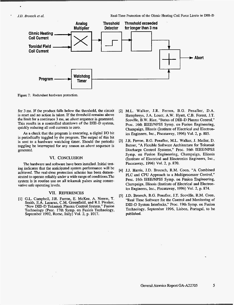
As noted above, the possibility of either a hardware or a software failure was anticipated. To insure that no damage would occur to the DIII-D system, two hardware subsystems were added to the EPSSIC suite. The first was a redundant cur- rent product monitor. The second was a watchdog timer specif- ically dedicated to the simultaneous ramp code. These two sys- tems are shown in Fig. 7. The redundant hardware circuit provides the functional monitoring of the current products. It does not have the sophisticated nominal value bounds check- ing, nor is its response to an excess current condition as subtle or as flexible as the software system.
Referring to Fig. 7, the analog signals measuring the ohmic heating coil current and the toroidal field coil current are sent to an analog multiplier. The output of the analog multi- plier is then sent to a threshold comparator. If the product of the two currents exceeds the 11,049 kA2 limit, the threshold circuit fires. The output of the circuit is digitally monitored
General Atomics Report GA-A22705 4
’ J.D. Broesch et al. Real-Time Protection of the Ohmic Heating Coil Force Limits in DIII-D
Analog Threshold Thresh old exceeded Multiplier Detector for longer than 3 ms
Ohmic Heating -,- Coil Current
Toroidal Field I -- Coil Current
t- I I
Watchdog Timer Program
Figure 7: Redundant hardware protection.
for 3 ms. If the product falls below the threshold, the circuit is reset and no action is taken. If the threshold remains above the limit for a continuos 3 ms, an abort sequence is generated. This results in a controlled shutdown of the DIII-D system, quickly reducing all coil currents to zero.
As a check that the program is executing, a digital I/O bit is periodically toggled by the program. The output of this bit is sent to a hardware watchdog timer. Should the periodic toggling be interrupted for any reason an abort sequence is generated.
VI. CONCLUSION The hardware and software have been installed. Initial test-
Abort
[2] M.L. Walker, J.R. Ferron, B.G. Penaflor, D.A. Humphreys, J.A. Leuer, A.W. Hyatt, C.B. Forest, J.T. Scoville, B.W. Rice, “Status of DID-D Plasma Control,” Proc. 16th IEEENPSS Symp. on Fusion Engineering, Champaign, Illinois (Institute of Electrical and Electron- ics Engineers, Inc., Piscataway, 1996) Vol. 2, p. 885.
[3] J.R. Ferron, B.G. Penaflor, M.L. Walker, J. Moller, D. Butner, “A Flexible Software Architecture for Tokamak Discharge Control Systems,” Proc. 16th IEEE/NPSS Symp. on Fusion Engineering, Champaign, Illinois (Institute of Electrical and Electronics Engineers, Inc., Piscataway, 1996) Vol. 2, p. 870.
[4] J.J. Harris, J.D. Broesch, R.M. Coon, “A Combined PLC and CPU Approach to a Multiprocessor Control,” proc. 16th IEEEmSS SYmP* On Fusion Champaign, Illinois (Institute of Electrical and Electron- ics Engineers, Inc., Piscataway, 1996) Vol. 2, p. 874.
ing indicates that the anticipated system performance will be achieved. The real-time protection scheme has been demon- strated to operate reliably under a wide range of conditions.The system is in routine use on all tokamak pulses using conser- vative safe operating levels.
[5] J.D. Broesch, B.G. Penaflor, J.T. Scoville, R.M. Coon, “Real Time Software for the Control and Monitoring of DIII-D System Interlocks,” Proc. 19th Symp. on Fusion Technology, September 1996, Lisbon, Portugal, to be published.
Vn. REFERENCES G.L. Campbell, J.R. Ferron, E. McKee, A. Nerem, T. Smith, E.A. Lazarus, C.M. Greenfield, and R.I. Pinsker, $‘New Dm-D Tokamak Plasma Control System,~9 Fusion Technology (Proc. 17th Symp. on Fusion Technology, September 1992, Rome, Italy) Vol. 2, p. 1017.
General Atomics Report GA-A22705 5
DOE


