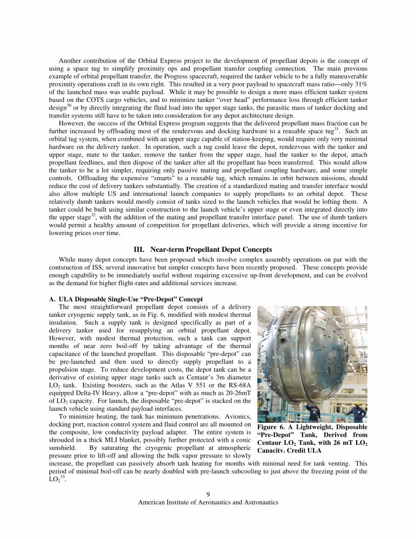
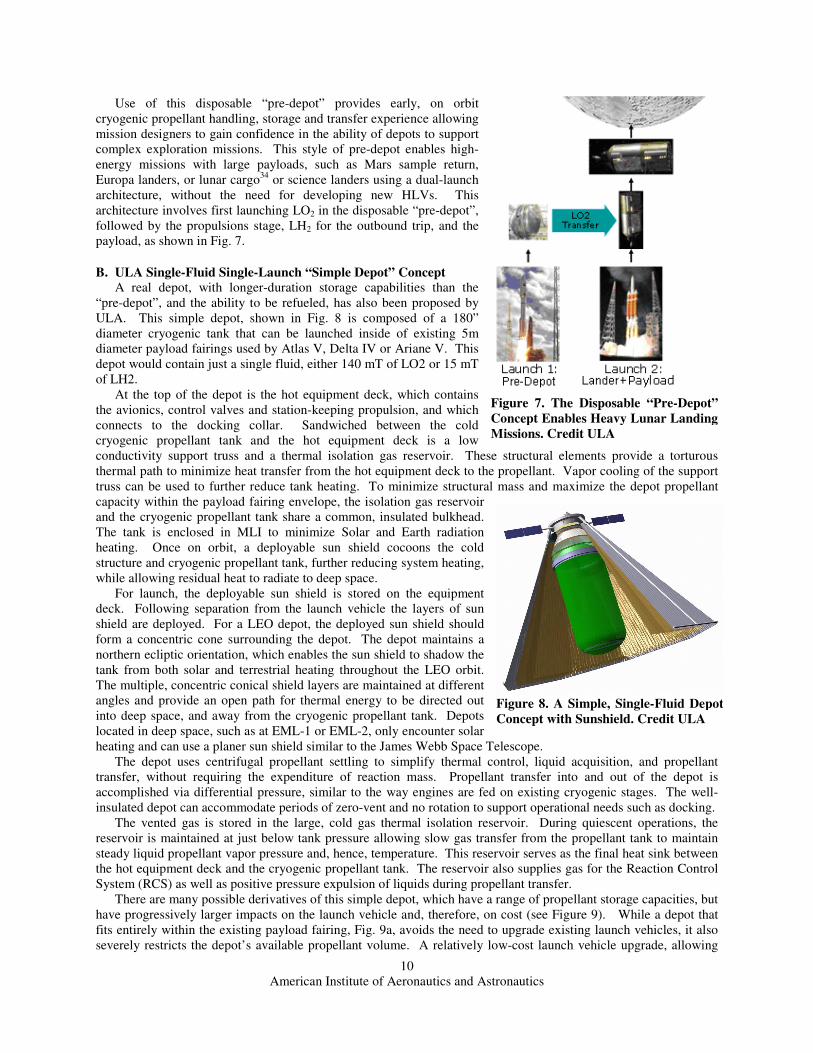
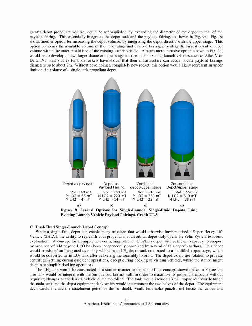
American Institute of Aeronautics and Astronautics 1 Realistic Near-Term Propellant Depots: Implementation of a Critical Spacefaring Capability Jonathan A. Goff 1 Masten Space Systems, Inc., Mojave, CA, 93501 Bernard F. Kutter 2 and Frank Zegler 3 United Launch Alliance, Littleton, CO, 80127 Dallas Bienhoff 4 The Boeing Company, Arlington, VA, 22202 Frank Chandler 5 The Boeing Company, Huntington Beach, CA 92647 Jeffrey Marchetta 6 The University of Memphis, Memphis, TN, 38152 Orbital cryogenic propellant depots and the ability to refuel spacecraft in orbit are critical capabilities for the expansion of human life throughout the Solar System. While depots have long been recognized as an important component of large-scale manned spaceflight efforts, questions about their technology readiness have so far prevented their implementation. Technological advancements in settled cryogenic handling, passive thermal control systems, and autonomous rendezvous and docking techniques make near-term implementation of cryogenic propellant depots significantly more realistic. Current work on flight-demonstration tools like ULA’s CRYOTE testbed, and Masten Space Systems’s XA-1.0 suborbital RLV provide methods for affordably retiring the remaining technical risks for cryogenic depots. Recent depot design concepts, built on high-TRL technologies and existing flight vehicle hardware, can enable easier implementation of first-generation propellant depots without requiring extensive development programs. Some concepts proposed by industry include disposable “pre-depots”, single-fluid simple depots, self-deployable dual-fluid single-launch depots using existing launchers and near-term launcher upgrades, and multi-launch modular depots. These concepts, particularly the dual-fluid single-launch depot enable robust exploration and commercial transportation throughout the inner Solar System, without the need for HLVs, while providing badly-needed markets to encourage the commercial development of more affordable access to space. 1 Propulsion Engineer, 1570 Sabovich St. Bldg 25, AIAA Member. 2 Sr. Staff, Manager Advanced Programs, P. O. Box 277005 MS U9115, AIAA Senior Member 3 Sr. Staff, Advanced Programs, United P.O. Box 277005 MS U9115, AIAA Member 4 Manager, In-Space & Surface Systems, Advanced Space Exploration, 1215 S. Clark St. MC 793C-G042, AIAA Senior Member. 5 Director, Propulsion & Cryogenic Technologies, 5301 Bolsa Ave/H012-2B201, Associate Fellow. 6 Associate Professor, Mechanical Engineering, 322D Engineering Sciences Building Memphis, TN 38152, AIAA Member.
Transcript
American Institute of Aeronautics and Astronautics
1
Realistic Near-Term Propellant Depots: Implementation of a
Critical Spacefaring Capability
Jonathan A. Goff1
Masten Space Systems, Inc., Mojave, CA, 93501
Bernard F. Kutter2 and Frank Zegler
3
United Launch Alliance, Littleton, CO, 80127
Dallas Bienhoff4
The Boeing Company, Arlington, VA, 22202
Frank Chandler5
The Boeing Company, Huntington Beach, CA 92647
Jeffrey Marchetta6
The University of Memphis, Memphis, TN, 38152
Orbital cryogenic propellant depots and the ability to refuel spacecraft in orbit are
critical capabilities for the expansion of human life throughout the Solar System. While
depots have long been recognized as an important component of large-scale manned
spaceflight efforts, questions about their technology readiness have so far prevented their
implementation. Technological advancements in settled cryogenic handling, passive thermal
control systems, and autonomous rendezvous and docking techniques make near-term
implementation of cryogenic propellant depots significantly more realistic. Current work
on flight-demonstration tools like ULA’s CRYOTE testbed, and Masten Space Systems’s
XA-1.0 suborbital RLV provide methods for affordably retiring the remaining technical
risks for cryogenic depots.
Recent depot design concepts, built on high-TRL technologies and existing flight vehicle
hardware, can enable easier implementation of first-generation propellant depots without
requiring extensive development programs. Some concepts proposed by industry include
American Institute of Aeronautics and Astronautics
12
controls for the LH2 half of the depot. The depot equipment deck would be attached to the LH2 tank and the LO2
tanks via low-conductivity materials.
The LO2 half of the depot would be constructed by adding several mission-specific modifications to the upper
stage used to orbit the vehicle. These additions would include MLI to provide in-space thermal insulation, docking
adapters and transfer interfaces mounted on the aft end of the stage, and some additional plumbing and controls for
depot operations. The stage would be converted to LO2 use after arriving at the destination orbit by first transferring
any remaining LH2 from the upper stage LH2 tank into the much larger depot LH2 tank. The upper stage LH2 tank
would then be vented to verify that no residual hydrogen remained. After allowing it to sit open to vacuum for some
time, the tank would be resealed and any remaining LO2 from the upper stage would be transferred from the upper
stage LO2 tank into the now-empty upper stage LH2 tank. The emptied upper stage LO2 tank would then serve as
the gas barrier to insulate the LO2 tank from heat flowing out of the aft section. For thermal control, the LO2 section
would take advantage of the fact that LH2 has a heat capacity ten times higher than LO2. By using the boiled
hydrogen to chill the LO2 tank and the interconnects between the tanks and hot structures, the depot would be able to
completely suppress LO2 boil-off, even though the LO2 section would not include its own sunshield, and in spite of
the rather severe thermal environment in LEO. As mentioned previously, the LH2 boil-off in this situation is still
less than the reaction mass requirements for station-keeping, so none of the boil-off LH2 is actually wasted.
An illustration of such a depot, based on the ULA ACES upper stage35
is shown below in Fig. 10. Using the
ACES stage, the depot would hold 121 mT of propellant (106 mT of LO2 and 15 mT of LH2). It should be noted
however, that this concept could also be based on existing stages such as the Centaur or Delta-IV Heavy upper
stages, or other proposed LO2/LH2 upper stages such as SpaceX’s Raptor, or Arianespace’s Ariane 5 ESC-B. A
depot using a stock Centaur as its LO2 tank would be able to hold about 52mT of LO2 and 14mT of LH2. The
resulting oxidizer to fuel (O/F) ratio is 3.7, which is far richer than the 5.5-6:1 ratio typical for existing upper stages,
in which only about 62mT of propellant would be usable. However, by stretching the Centaur stage LH2 tank by
about 1.5m (and shortening the depot tank by the same amount to keep it within the boundaries of the existing
fairings), the total propellant loads become about 64mT of LO2 and 12mT of LH2, giving a more useful O/F ratio of
5.4. This would leave some extra LH2 tankage to handle the higher boil-off. Tank barrel stretches are far less
expensive than changes to the diameter of the tanks, which require redesigning the complicated aft-end of the rocket,
new tooling and qualification testing. In fact, many of the upgrades to the Centaur stage over the years have
consisted of such barrel stretching36
.
Figure 10. A Single Launch, Dual-Fluid Propellant Depot. Credit ULA
American Institute of Aeronautics and Astronautics
13
By combining a depot tank with a propulsive stage, this depot concept is able to self-deploy to locations beyond
LEO, such as at EML-1 or -2, or even as far as Mars orbit. By placing one of these depots in LEO and one in either
EML-1 or -2, ESAS-class lunar missions can be performed without requiring vehicles bigger than existing
launchers, and without requiring a new Earth departure stage. The severe thermal environment in LEO causes a
substantial amount of propellant boil-off over the course of a year. EML-1 or -2 depots are in a much more benign
thermal environment, with very low boil-off levels. This leads to the conclusion that the best way to use a depot
system like this is to forward propellants on from the LEO depot to the EML-1 or -2 depot as quickly as possible.
The higher the tempo of flights beyond LEO, the lower the percentage of propellants lost to boil-off in LEO. With a
decent operational tempo, boil-off losses for this system can be kept to low single-digit percentages of the yearly
propellant throughput.
D. Boeing Multi-Launch Dual-Fluid Depot Concept
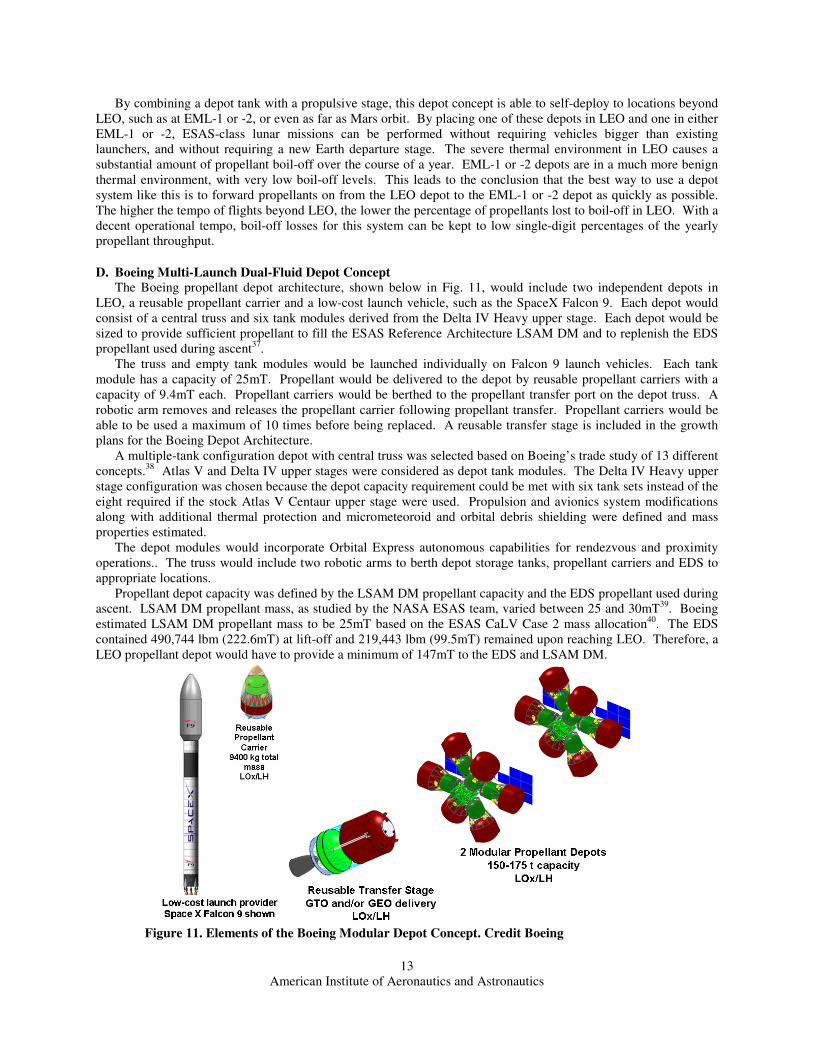
The Boeing propellant depot architecture, shown below in Fig. 11, would include two independent depots in
LEO, a reusable propellant carrier and a low-cost launch vehicle, such as the SpaceX Falcon 9. Each depot would
consist of a central truss and six tank modules derived from the Delta IV Heavy upper stage. Each depot would be
sized to provide sufficient propellant to fill the ESAS Reference Architecture LSAM DM and to replenish the EDS
propellant used during ascent37
.
The truss and empty tank modules would be launched individually on Falcon 9 launch vehicles. Each tank
module has a capacity of 25mT. Propellant would be delivered to the depot by reusable propellant carriers with a
capacity of 9.4mT each. Propellant carriers would be berthed to the propellant transfer port on the depot truss. A
robotic arm removes and releases the propellant carrier following propellant transfer. Propellant carriers would be
able to be used a maximum of 10 times before being replaced. A reusable transfer stage is included in the growth
plans for the Boeing Depot Architecture.
A multiple-tank configuration depot with central truss was selected based on Boeing’s trade study of 13 different
concepts.38
Atlas V and Delta IV upper stages were considered as depot tank modules. The Delta IV Heavy upper
stage configuration was chosen because the depot capacity requirement could be met with six tank sets instead of the
eight required if the stock Atlas V Centaur upper stage were used. Propulsion and avionics system modifications
along with additional thermal protection and micrometeoroid and orbital debris shielding were defined and mass
properties estimated.
The depot modules would incorporate Orbital Express autonomous capabilities for rendezvous and proximity
operations.. The truss would include two robotic arms to berth depot storage tanks, propellant carriers and EDS to
appropriate locations.
Propellant depot capacity was defined by the LSAM DM propellant capacity and the EDS propellant used during
ascent. LSAM DM propellant mass, as studied by the NASA ESAS team, varied between 25 and 30mT39
. Boeing
estimated LSAM DM propellant mass to be 25mT based on the ESAS CaLV Case 2 mass allocation40
. The EDS
contained 490,744 lbm (222.6mT) at lift-off and 219,443 lbm (99.5mT) remained upon reaching LEO. Therefore, a
LEO propellant depot would have to provide a minimum of 147mT to the EDS and LSAM DM.
Figure 11. Elements of the Boeing Modular Depot Concept. Credit Boeing
American Institute of Aeronautics and Astronautics
14
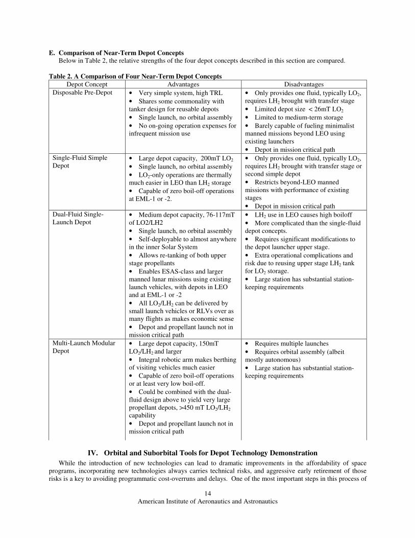
E. Comparison of Near-Term Depot Concepts
Below in Table 2, the relative strengths of the four depot concepts described in this section are compared.
IV. Orbital and Suborbital Tools for Depot Technology Demonstration
While the introduction of new technologies can lead to dramatic improvements in the affordability of space
programs, incorporating new technologies always carries technical risks, and aggressive early retirement of those
risks is a key to avoiding programmatic cost-overruns and delays. One of the most important steps in this process of
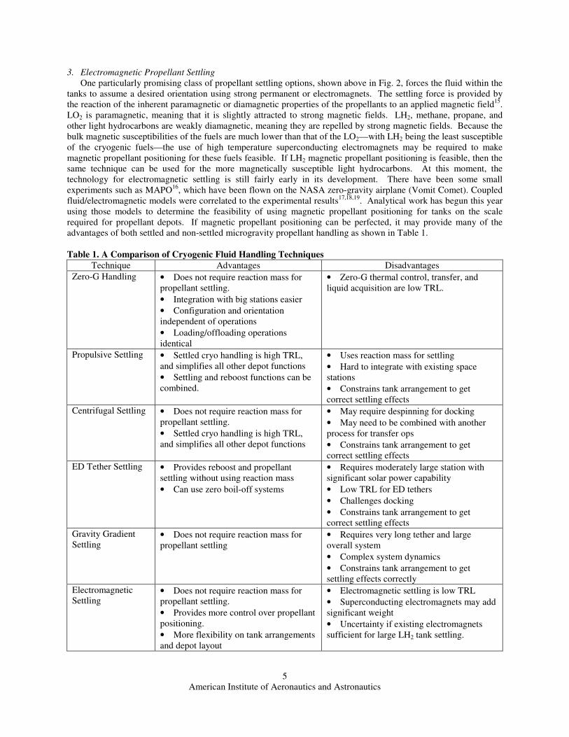
Table 2. A Comparison of Four Near-Term Depot Concepts
Depot Concept Advantages Disadvantages
Disposable Pre-Depot • Very simple system, high TRL
• Shares some commonality with
tanker design for reusable depots
• Single launch, no orbital assembly
• No on-going operation expenses for
infrequent mission use
• Only provides one fluid, typically LO2,
requires LH2 brought with transfer stage
• Limited depot size < 26mT LO2
• Limited to medium-term storage
• Barely capable of fueling minimalist
manned missions beyond LEO using
existing launchers
• Depot in mission critical path
Single-Fluid Simple
Depot • Large depot capacity, 200mT LO2
• Single launch, no orbital assembly
• LO2-only operations are thermally
much easier in LEO than LH2 storage
• Capable of zero boil-off operations
at EML-1 or -2.
• Only provides one fluid, typically LO2,
requires LH2 brought with transfer stage or
second simple depot
• Restricts beyond-LEO manned
missions with performance of existing
stages
• Depot in mission critical path
Dual-Fluid Single-
Launch Depot • Medium depot capacity, 76-117mT
of LO2/LH2
• Single launch, no orbital assembly
• Self-deployable to almost anywhere
in the inner Solar System
• Allows re-tanking of both upper
stage propellants
• Enables ESAS-class and larger
manned lunar missions using existing
launch vehicles, with depots in LEO
and at EML-1 or -2
• All LO2/LH2 can be delivered by
small launch vehicles or RLVs over as
many flights as makes economic sense
• Depot and propellant launch not in
mission critical path
• LH2 use in LEO causes high boiloff
• More complicated than the single-fluid
depot concepts.
• Requires significant modifications to
the depot launcher upper stage.
• Extra operational complications and
risk due to reusing upper stage LH2 tank
for LO2 storage.
• Large station has substantial station-
keeping requirements
Multi-Launch Modular
Depot • Large depot capacity, 150mT
LO2/LH2 and larger
• Integral robotic arm makes berthing
of visiting vehicles much easier
• Capable of zero boil-off operations
or at least very low boil-off.
• Could be combined with the dual-
fluid design above to yield very large
propellant depots, >450 mT LO2/LH2
capability
• Depot and propellant launch not in
mission critical path
• Requires multiple launches
• Requires orbital assembly (albeit
mostly autonomous)
• Large station has substantial station-
keeping requirements
American Institute of Aeronautics and Astronautics
15
space technology maturation, especially for systems involving complicated phenomena like cryogenic fluid
management, is flight testing in the space environment.41
Unfortunately, this step is often hampered by the high cost
and infrequent opportunities for flight testing. In many cases this prevents adequate experimentation with
alternative approaches to truly evaluate their feasibility. Space architectures often suffer thereby from conceptual
lock-in, where judgment decisions made during early phases with marginal and incomplete data win out over
promising new concepts42
. Recent progress in developing orbital testbeds for cryogenic fluid management and in
the fielding of commercial reusable suborbital vehicles means that a wider range of technological solutions can now
be affordably and extensively tested. These capabilities allow various propellant depot technologies to be rapidly
matured, while simultaneously increasing the probability that promising alternative technological approaches will be
adequately investigated as well.
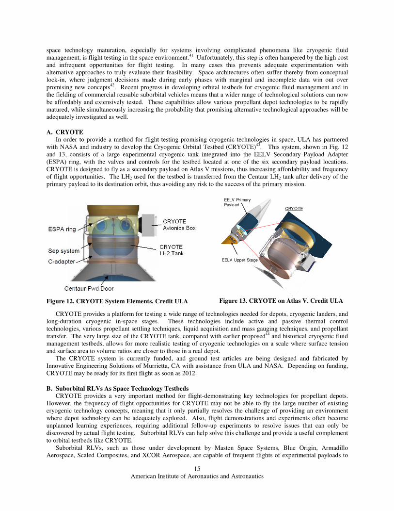
A. CRYOTE
In order to provide a method for flight-testing promising cryogenic technologies in space, ULA has partnered
with NASA and industry to develop the Cryogenic Orbital Testbed (CRYOTE)43
. This system, shown in Fig. 12
and 13, consists of a large experimental cryogenic tank integrated into the EELV Secondary Payload Adapter
(ESPA) ring, with the valves and controls for the testbed located at one of the six secondary payload locations.
CRYOTE is designed to fly as a secondary payload on Atlas V missions, thus increasing affordability and frequency
of flight opportunities. The LH2 used for the testbed is transferred from the Centaur LH2 tank after delivery of the
primary payload to its destination orbit, thus avoiding any risk to the success of the primary mission.
CRYOTE provides a platform for testing a wide range of technologies needed for depots, cryogenic landers, and
long-duration cryogenic in-space stages. These technologies include active and passive thermal control
technologies, various propellant settling techniques, liquid acquisition and mass gauging techniques, and propellant
transfer. The very large size of the CRYOTE tank, compared with earlier proposed44
and historical cryogenic fluid
management testbeds, allows for more realistic testing of cryogenic technologies on a scale where surface tension
and surface area to volume ratios are closer to those in a real depot.
The CRYOTE system is currently funded, and ground test articles are being designed and fabricated by
Innovative Engineering Solutions of Murrietta, CA with assistance from ULA and NASA. Depending on funding,
CRYOTE may be ready for its first flight as soon as 2012.
B. Suborbital RLVs As Space Technology Testbeds
CRYOTE provides a very important method for flight-demonstrating key technologies for propellant depots.
However, the frequency of flight opportunities for CRYOTE may not be able to fly the large number of existing
cryogenic technology concepts, meaning that it only partially resolves the challenge of providing an environment
where depot technology can be adequately explored. Also, flight demonstrations and experiments often become
unplanned learning experiences, requiring additional follow-up experiments to resolve issues that can only be
discovered by actual flight testing. Suborbital RLVs can help solve this challenge and provide a useful complement
to orbital testbeds like CRYOTE.
Suborbital RLVs, such as those under development by Masten Space Systems, Blue Origin, Armadillo
Aerospace, Scaled Composites, and XCOR Aerospace, are capable of frequent flights of experimental payloads to
CRY OTE
EELV Upper Stage
EELV Pr imary Payload
Figure 13. CRYOTE on Atlas V. Credit ULA
Figure 12. CRYOTE System Elements. Credit ULA
American Institute of Aeronautics and Astronautics
16
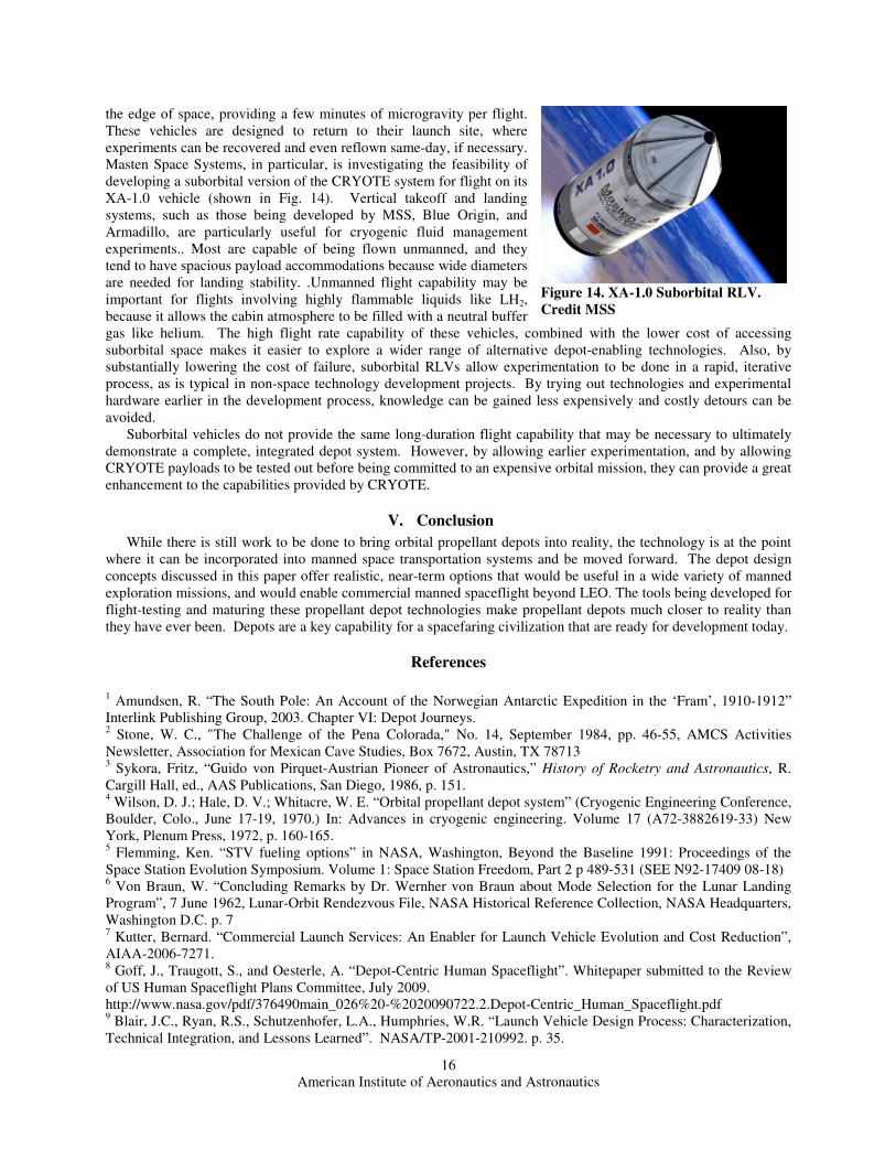
the edge of space, providing a few minutes of microgravity per flight.
These vehicles are designed to return to their launch site, where
experiments can be recovered and even reflown same-day, if necessary.
Masten Space Systems, in particular, is investigating the feasibility of
developing a suborbital version of the CRYOTE system for flight on its
XA-1.0 vehicle (shown in Fig. 14). Vertical takeoff and landing
systems, such as those being developed by MSS, Blue Origin, and
Armadillo, are particularly useful for cryogenic fluid management
experiments.. Most are capable of being flown unmanned, and they
tend to have spacious payload accommodations because wide diameters
are needed for landing stability. .Unmanned flight capability may be
important for flights involving highly flammable liquids like LH2,
because it allows the cabin atmosphere to be filled with a neutral buffer
gas like helium. The high flight rate capability of these vehicles, combined with the lower cost of accessing
suborbital space makes it easier to explore a wider range of alternative depot-enabling technologies. Also, by
substantially lowering the cost of failure, suborbital RLVs allow experimentation to be done in a rapid, iterative
process, as is typical in non-space technology development projects. By trying out technologies and experimental
hardware earlier in the development process, knowledge can be gained less expensively and costly detours can be
avoided.
Suborbital vehicles do not provide the same long-duration flight capability that may be necessary to ultimately
demonstrate a complete, integrated depot system. However, by allowing earlier experimentation, and by allowing
CRYOTE payloads to be tested out before being committed to an expensive orbital mission, they can provide a great
enhancement to the capabilities provided by CRYOTE.
V. Conclusion
While there is still work to be done to bring orbital propellant depots into reality, the technology is at the point
where it can be incorporated into manned space transportation systems and be moved forward. The depot design
concepts discussed in this paper offer realistic, near-term options that would be useful in a wide variety of manned
exploration missions, and would enable commercial manned spaceflight beyond LEO. The tools being developed for
flight-testing and maturing these propellant depot technologies make propellant depots much closer to reality than
they have ever been. Depots are a key capability for a spacefaring civilization that are ready for development today.
References
1 Amundsen, R. “The South Pole: An Account of the Norwegian Antarctic Expedition in the ‘Fram’, 1910-1912”
Interlink Publishing Group, 2003. Chapter VI: Depot Journeys. 2 Stone, W. C., "The Challenge of the Pena Colorada," No. 14, September 1984, pp. 46-55, AMCS Activities
Newsletter, Association for Mexican Cave Studies, Box 7672, Austin, TX 78713 3 Sykora, Fritz, “Guido von Pirquet-Austrian Pioneer of Astronautics,” History of Rocketry and Astronautics, R.
Cargill Hall, ed., AAS Publications, San Diego, 1986, p. 151. 4 Wilson, D. J.; Hale, D. V.; Whitacre, W. E. “Orbital propellant depot system” (Cryogenic Engineering Conference,
Boulder, Colo., June 17-19, 1970.) In: Advances in cryogenic engineering. Volume 17 (A72-3882619-33) New
York, Plenum Press, 1972, p. 160-165. 5 Flemming, Ken. “STV fueling options” in NASA, Washington, Beyond the Baseline 1991: Proceedings of the
Space Station Evolution Symposium. Volume 1: Space Station Freedom, Part 2 p 489-531 (SEE N92-17409 08-18) 6 Von Braun, W. “Concluding Remarks by Dr. Wernher von Braun about Mode Selection for the Lunar Landing
Program”, 7 June 1962, Lunar-Orbit Rendezvous File, NASA Historical Reference Collection, NASA Headquarters,
Washington D.C. p. 7 7 Kutter, Bernard. “Commercial Launch Services: An Enabler for Launch Vehicle Evolution and Cost Reduction”,
AIAA-2006-7271. 8 Goff, J., Traugott, S., and Oesterle, A. “Depot-Centric Human Spaceflight”. Whitepaper submitted to the Review
of US Human Spaceflight Plans Committee, July 2009.


![[Pixar] Big Data, Big Depots](https://static.documents.pub/doc/80x56/5582937bd8b42ac9798b548d/pixar-big-data-big-depots.jpg)


