080729 80002165 Questions? Contact this Professional Installer : Company : _________________________________________ _________________________________________ Phone : _________________________________________ Installer : ________________________ Date : __________ GM C4500/C5500 4X4 REAR STABILIZER BAR KIT 2006-NEWER MODELS For Installation with 8M000085 UltraRide Suspension Link Kit Part Number: 800M1059 OWNERS MANUAL
Transcript
080729 80002165
Questions? Contact this Professional Installer :
Company : _________________________________________
_________________________________________
Phone : _________________________________________
Installer : ________________________ Date : __________
GM C4500/C5500 4X4
REAR STABILIZER BAR KIT
2006-NEWER MODELS For Installation with 8M000085
UltraRide Suspension
Link Kit Part Number: 800M1059
OW
NE
RS
MA
NU
AL
2
Proper tightening of U-Bolt nuts and mounting nuts are required for proper operation. Need for proper Torque value is indicated by wrench symbol and values will be found in Table 10-1 in the Final
Assembly section of the instructions. Failure to maintain proper torque can cause component failure resulting in accident with consequent injury.
1. INTRODUCTION NOTE: It is important that the entire installation instructions be read thoroughly before proceeding with suspension installation.
PRODUCT INSTALLER RESPONSIBILITIES
� Installer is responsible for installing the product in accordance with Link Mfg. specifications and installation instructions.
� Installer is responsible for providing proper suspension to vehicle attachments.
� Installer is responsible for assuring necessary clearance for vehicle and suspension components, such as axle, wheels, tires, exhaust, and air springs to ensure safe operation.
� Installer is responsible for advising the owner of proper use, service and required maintenance, and for supplying maintenance and other instruction supplied by Link Mfg.
SAFETY SYMBOLS, TORQUE SYMBOL, and NOTES
WARNING! A correct installation must result in the suspension and axle being “loaded” within the range specified by axle and suspension manufacturers. Please check vehicle specifications and intended usage to insure axle will be within Gross Axle Weight Rating
(GAWR). No alteration of any suspension component is permitted. Link Mfg. Is not responsible for damages from improper installation or operations beyond design capability. Link Mfg. In its sole dis-cretion shall determine whether or not any product is defective or otherwise covered by warranty.
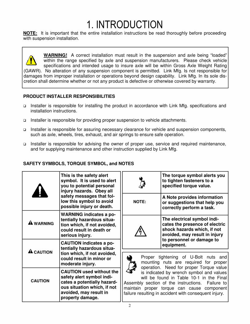
The torque symbol alerts you to tighten fasteners to a specified torque value.
NOTE:
A Note provides information or suggestions that help you correctly perform a task.
The electrical symbol indi-cates the presence of electric shock hazards which, if not avoided, may result in injury to personnel or damage to equipment.
This is the safety alert symbol. It is used to alert you to potential personal injury hazards. Obey all safety messages that fol-low this symbol to avoid possible injury or death.
WARNING
WARNING indicates a po-tentially hazardous situa-tion which, if not avoided, could result in death or serious injury.
CAUTION
CAUTION indicates a po-tentially hazardous situa-tion which, if not avoided, could result in minor or moderate injury.
CAUTION
CAUTION used without the safety alert symbol indi-cates a potentially hazard-ous situation which, if not avoided, may result in property damage.
3
INSTALLATION NOTES:
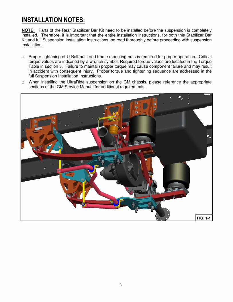
NOTE: Parts of the Rear Stabilizer Bar Kit need to be installed before the suspension is completely installed. Therefore, it is important that the entire installation instructions, for both this Stabilizer Bar Kit and full Suspension Installation Instructions, be read thoroughly before proceeding with suspension installation.
� Proper tightening of U-Bolt nuts and frame mounting nuts is required for proper operation. Critical torque values are indicated by a wrench symbol. Required torque values are located in the Torque Table in section 3. Failure to maintain proper torque may cause component failure and may result in accident with consequent injury. Proper torque and tightening sequence are addressed in the full Suspension Installation Instructions.
� When installing the UltraRide suspension on the GM chassis, please reference the appropriate sections of the GM Service Manual for additional requirements.
FIG. 1-1
4
2. LOWER SPRING PLATE INSTALLATION
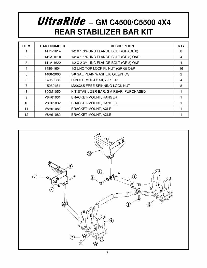
1. Review Figures in Section 2 and Parts List/Drawing (Section 4) to acquaint yourself with the various parts of the UltraRide Rear Stabilizer Bar Kit. Assemble components loosely as described below and torque later in Section 3.
2. If STABILIZER BAR KIT is being added to an existing UltraRide suspension (Part Number 8M000085) The LOWER SPRING PLATE BRACKETS must first be removed. This can be done by removing the M20 FLANGE NUTS located on the underside of these brackets. Discard the existing U-bolts and nuts, as new ones are provided with this kit.
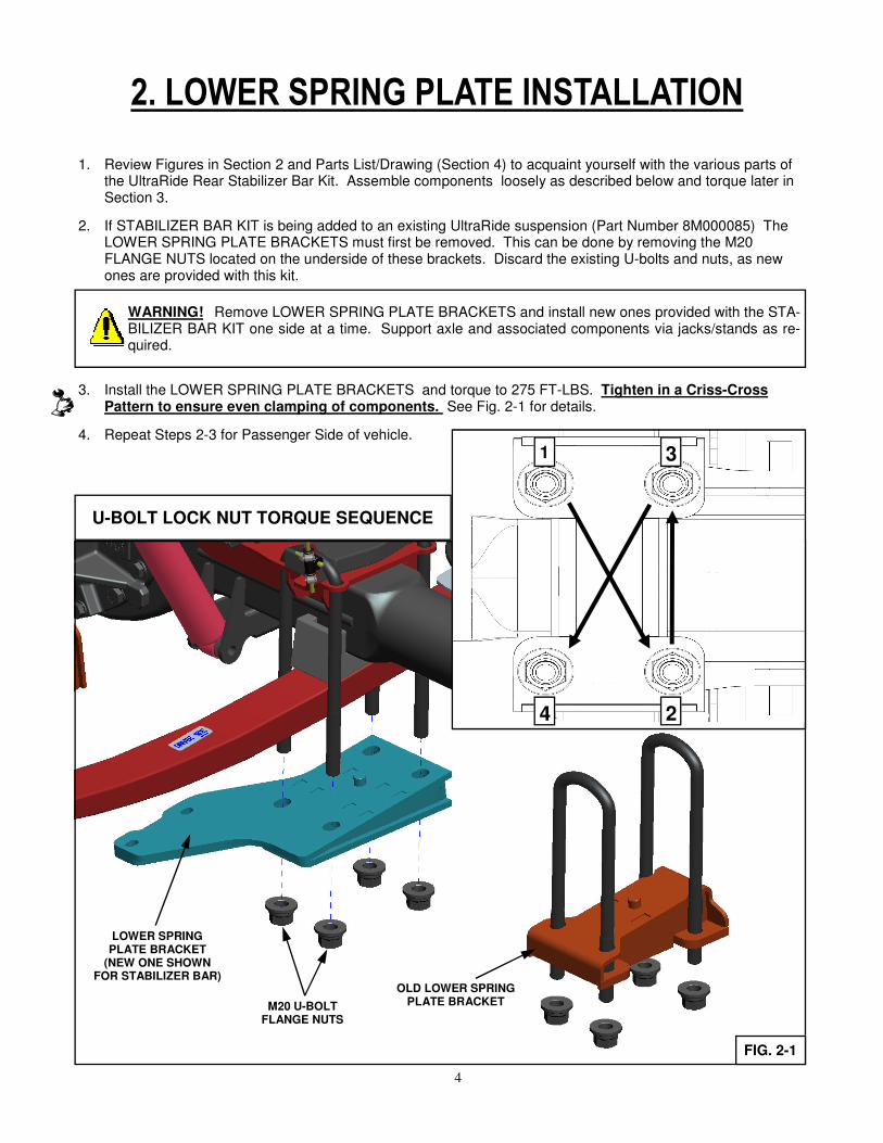
3. Install the LOWER SPRING PLATE BRACKETS and torque to 275 FT-LBS. Tighten in a Criss-Cross Pattern to ensure even clamping of components. See Fig. 2-1 for details.
4. Repeat Steps 2-3 for Passenger Side of vehicle.
FIG. 2-1
M20 U-BOLT FLANGE NUTS
LOWER SPRING PLATE BRACKET
(NEW ONE SHOWN FOR STABILIZER BAR)
WARNING! Remove LOWER SPRING PLATE BRACKETS and install new ones provided with the STA-BILIZER BAR KIT one side at a time. Support axle and associated components via jacks/stands as re-quired.
OLD LOWER SPRING PLATE BRACKET
1
2
3
4
U-BOLT LOCK NUT TORQUE SEQUENCE
5
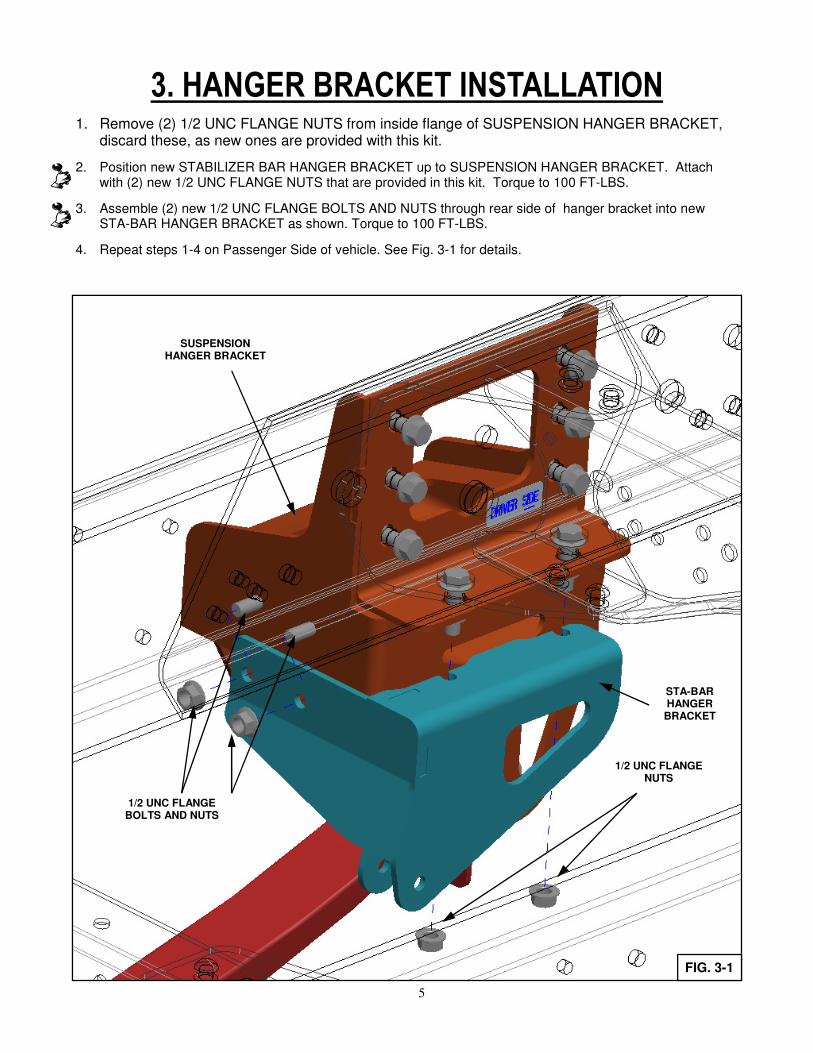
3. HANGER BRACKET INSTALLATION
1. Remove (2) 1/2 UNC FLANGE NUTS from inside flange of SUSPENSION HANGER BRACKET, discard these, as new ones are provided with this kit.
2. Position new STABILIZER BAR HANGER BRACKET up to SUSPENSION HANGER BRACKET. Attach with (2) new 1/2 UNC FLANGE NUTS that are provided in this kit. Torque to 100 FT-LBS.
3. Assemble (2) new 1/2 UNC FLANGE BOLTS AND NUTS through rear side of hanger bracket into new STA-BAR HANGER BRACKET as shown. Torque to 100 FT-LBS.
4. Repeat steps 1-4 on Passenger Side of vehicle. See Fig. 3-1 for details.
1/2 UNC FLANGE NUTS
SUSPENSION HANGER BRACKET
1/2 UNC FLANGE BOLTS AND NUTS
STA-BAR HANGER
BRACKET
FIG. 3-1
6
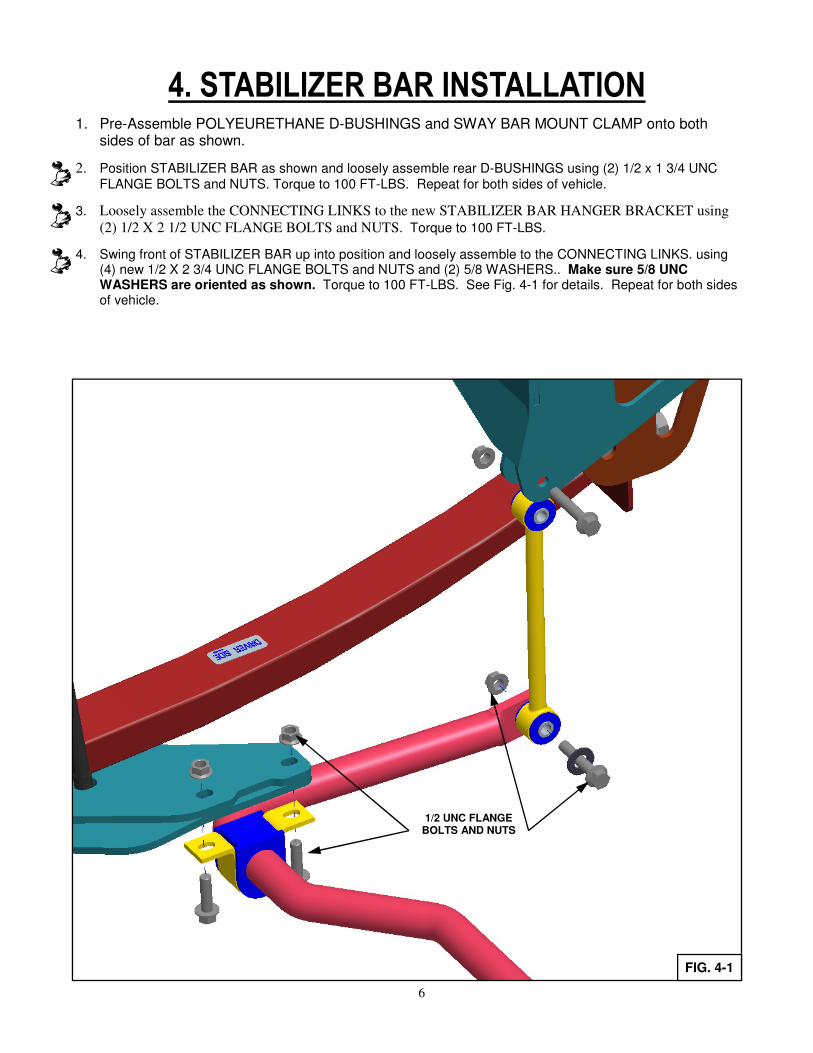
4. STABILIZER BAR INSTALLATION
1. Pre-Assemble POLYEURETHANE D-BUSHINGS and SWAY BAR MOUNT CLAMP onto both sides of bar as shown.
2. Position STABILIZER BAR as shown and loosely assemble rear D-BUSHINGS using (2) 1/2 x 1 3/4 UNC FLANGE BOLTS and NUTS. Torque to 100 FT-LBS. Repeat for both sides of vehicle.
3. Loosely assemble the CONNECTING LINKS to the new STABILIZER BAR HANGER BRACKET using
(2) 1/2 X 2 1/2 UNC FLANGE BOLTS and NUTS. Torque to 100 FT-LBS.
4. Swing front of STABILIZER BAR up into position and loosely assemble to the CONNECTING LINKS. using(4) new 1/2 X 2 3/4 UNC FLANGE BOLTS and NUTS and (2) 5/8 WASHERS.. Make sure 5/8 UNC WASHERS are oriented as shown. Torque to 100 FT-LBS. See Fig. 4-1 for details. Repeat for both sides of vehicle.
1/2 UNC FLANGE BOLTS AND NUTS
FIG. 4-1
7
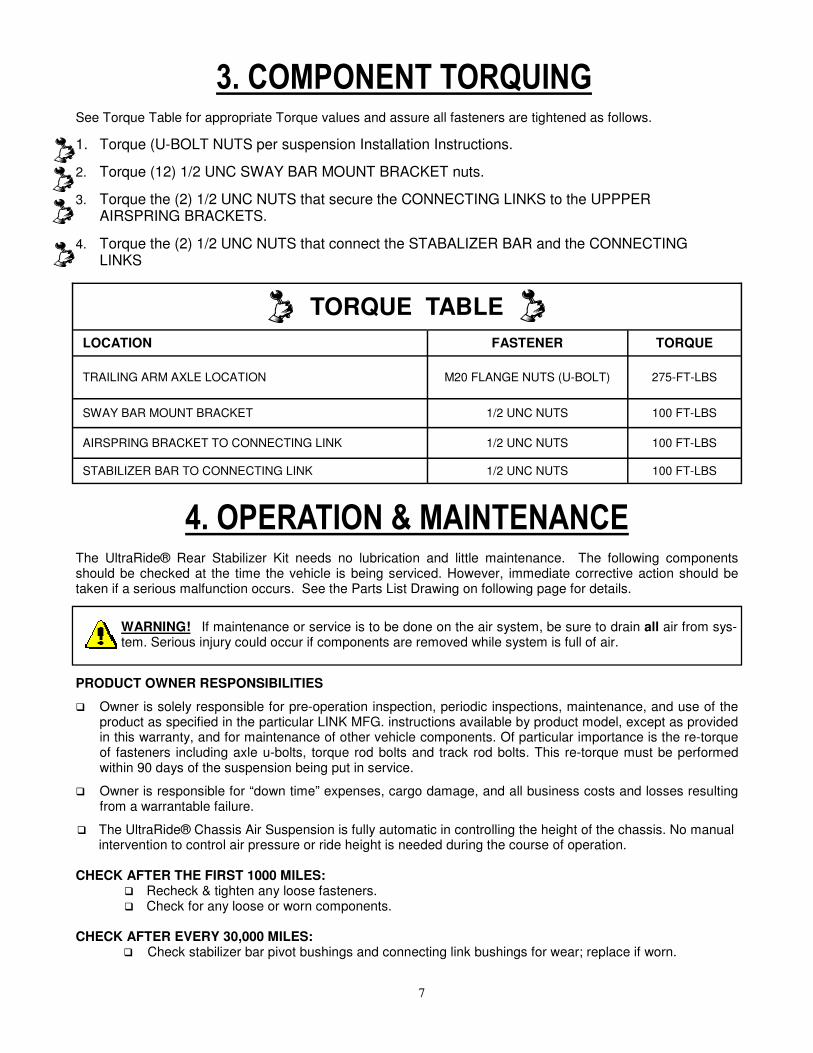
3. COMPONENT TORQUING
See Torque Table for appropriate Torque values and assure all fasteners are tightened as follows.
1. Torque (U-BOLT NUTS per suspension Installation Instructions.
2. Torque (12) 1/2 UNC SWAY BAR MOUNT BRACKET nuts.
3. Torque the (2) 1/2 UNC NUTS that secure the CONNECTING LINKS to the UPPPER AIRSPRING BRACKETS.
4. Torque the (2) 1/2 UNC NUTS that connect the STABALIZER BAR and the CONNECTING LINKS
TORQUE TABLE
LOCATION FASTENER TORQUE
TRAILING ARM AXLE LOCATION M20 FLANGE NUTS (U-BOLT) 275-FT-LBS
SWAY BAR MOUNT BRACKET 1/2 UNC NUTS 100 FT-LBS
AIRSPRING BRACKET TO CONNECTING LINK 1/2 UNC NUTS 100 FT-LBS
STABILIZER BAR TO CONNECTING LINK 1/2 UNC NUTS 100 FT-LBS
4. OPERATION & MAINTENANCE The UltraRide® Rear Stabilizer Kit needs no lubrication and little maintenance. The following components should be checked at the time the vehicle is being serviced. However, immediate corrective action should be taken if a serious malfunction occurs. See the Parts List Drawing on following page for details.
PRODUCT OWNER RESPONSIBILITIES
� Owner is solely responsible for pre-operation inspection, periodic inspections, maintenance, and use of the product as specified in the particular LINK MFG. instructions available by product model, except as provided in this warranty, and for maintenance of other vehicle components. Of particular importance is the re-torque of fasteners including axle u-bolts, torque rod bolts and track rod bolts. This re-torque must be performed within 90 days of the suspension being put in service.
� Owner is responsible for “down time” expenses, cargo damage, and all business costs and losses resulting from a warrantable failure.
� The UltraRide® Chassis Air Suspension is fully automatic in controlling the height of the chassis. No manual intervention to control air pressure or ride height is needed during the course of operation.
CHECK AFTER THE FIRST 1000 MILES:
� Recheck & tighten any loose fasteners. � Check for any loose or worn components.
CHECK AFTER EVERY 30,000 MILES:
� Check stabilizer bar pivot bushings and connecting link bushings for wear; replace if worn.
WARNING! If maintenance or service is to be done on the air system, be sure to drain all air from sys-tem. Serious injury could occur if components are removed while system is full of air.