Md Mahbubul Islam,a Alireza Ostadhossein,b Oleg Borodin,c A. Todd Yeates,d
William W. Tipton,e Richard G. Hennig,e Nitin Kumarf and Adri C. T. van Duin*a
Sulfur is a very promising cathode material for rechargeable energy storage devices. However, sulfur
cathodes undergo a noticeable volume variation upon cycling, which induces mechanical stress. In spite
of intensive investigation of the electrochemical behavior of the lithiated sulfur compounds, their
mechanical properties are not very well understood. In order to fill this gap, we developed a ReaxFF
interatomic potential to describe Li–S interactions and performed molecular dynamics (MD) simulations to
study the structural, mechanical, and kinetic behavior of the amorphous lithiated sulfur (a-LixS)
compounds. We examined the effect of lithiation on material properties such as ultimate strength, yield
strength, and Young’s modulus. Our results suggest that with increasing lithium content, the strength of
lithiated sulfur compounds improves, although this increment is not linear with lithiation. The diffusion
coefficients of both lithium and sulfur were computed for the a-LixS system at various stages of Li-loading.
A grand canonical Monte Carlo (GCMC) scheme was used to calculate the open circuit voltage profile
during cell discharge. The Li–S binary phase diagram was constructed using genetic algorithm based tools.
Overall, these simulation results provide insight into the behavior of sulfur based cathode materials that
are needed for developing lithium–sulfur batteries.
1. Introduction
Over the last two decades, lithium-ion batteries (LIBs) have becomeubiquitous in portable consumer electronics. However, the limitedcapacities of LIBs impede their application in electric vehicles (EVs)and smart-grids.1,2 Automotive applications require significantimprovements in the capacity of electrode materials to allow longtrips (i.e. 4300 km) in a single charging.3,4 Sulfur based cathodematerials for Li–S batteries are considered a very promisingalternative to the conventional transition metal oxide/phosphatecathodes5 due to their high capacity, energy density, non-toxicity,and natural abundance.6 The theoretical specific capacity ofsulfur is 1672 mA h g�1, which is 10 times higher than that of
commonly-used LiCoO2 cathodes, and it has a theoreticalspecific energy density of 2600 W h kg�1, assuming completereaction to Li2S.3,6,7
In current battery technologies, the capacity of the cathodesis substantially lower than that of commercially available anodematerials, such as graphite. Moreover, high capacity Si and Snbased anodes are being developed.8–12 These materials havetheoretical specific capacities of 4200 mA h g�1 and 900 mA h g�1,respectively.13 However, any breakthrough in the capacity ofthe anode materials must be accompanied by improvements tothe cathode to develop high-performance batteries to meet nextgeneration energy demand.
Although sulfur exhibits great promise, commercializationof Li–S batteries has been thwarted by several complex problems,such as significant structural and volume changes of the cathode,the high reactivity of lithium, dissolution of intermediatepolysulfides into the electrolytes, poor electronic and ionic conduc-tivities of sulfur and Li2S, and safety concerns.14–18 Volume expan-sion of the sulfur composite cathode occurs during discharging(lithium intercalation) and contraction during charging (lithiumde-intercalation).19 This active material breathing induces stress inthe cathode material, and the active material loses its electricalcontact with the conductive substrate or with the current collector.20
Numerous approaches have been reported in the literature toaccommodate volume changes, including sulfur-coated multi-walled carbon nanotubes composite material,21,22 graphene
a Department of Mechanical and Nuclear Engineering, The Pennsylvania State
University, University Park, PA 16802, USA. E-mail: [email protected];
Fax: +1-814-863-6382; Tel: +1-814-863-6277b Department of Engineering Science and Mechanics, The Pennsylvania State
University, University Park, PA 16802, USAc Electrochemistry Branch, US Army Research Laboratory, 2800 Powder Mill Rd.,
Adelphi, MD 20783, USAd Materials and Manufacturing Directorate, Air Force Research Laboratory,
AFRL/RXBN, Wright-Patterson AFB, OH 45433-7750, USAe Department of Materials Science and Engineering, Cornell University, Ithaca,
NY 14853, USAf Sandia National Laboratories, Albuquerque, New Mexico 87185, USA
† Electronic supplementary information (ESI) available. See DOI: 10.1039/c4cp04532g
Received 7th October 2014,Accepted 12th December 2014
wrapped sulfur particles,23 and reduced graphene oxide encapsu-lated sulfur.24 These approaches demonstrate high initial capacity,but rapid capacity fading due to cathode degradation still greatlylimits performance.
Furthermore, a great deal of recent studies of Li–S batteriesused elemental lithium as anode material.14,20,25–27 The lithiumanode yields high capacity, but it has low cycling efficiency andforms lithium dendrites on the anode surface during cyclingthat can penetrate the separator leading to short circuit.25,28
To inhibit dendrite formation, Li-ion conducting passivationlayers using Li3N,29 Li2CO3,30 and LiPON,31 have been suggested.These protective thin films suppress lithium dendrite formation,but a high cost of fabrication has limited their use.32 Lithiumdendrite formation issues have not yet been fully resolved,restricting the use of Li–metal anodes in commercial batteries.33
Recently, lithium–metal free batteries that use silicon or tininstead of elemental lithium in the anode have received muchattention due to improved safety properties.34 In these systems,neither the sulfur cathode nor the Si or Sn anode containslithium originally, so either the cathode or the anode must beprelithiated to provide a lithium source. To this end, systemscomposed of Li2S cathodes and Si anodes have been studied byseveral previous authors.16,35,36 However, relatively low lithiumdiffusivity and high electronic resistivity cause a large potentialbarrier to activate the Li2S cathode.35 He and coworkers37 investi-gated a prelithiated sulfur composite/graphite lithium ion cell, whichwas fabricated using electrochemical lithiation. Li-ion diffusivity inlithiated sulfur depends on the lithium concentration, and lithiatedcathode materials possess lower specific capacity than their non-lithiated counterparts.38
While significant progress towards improving performanceof the Li–S battery has been achieved,17 there is a lack ofunderstanding of mechanical and structural properties ofthe lithiated sulfur compounds. Molecular dynamics (MD)simulations are well suited for examination of the a-LixS as afunction of lithiation provided an accurate representationof the intermolecular interactions and chemical reactions isachieved. Such simulations are expected to provide funda-mental understanding of the material properties such as under-standing the morphological changes a-LixS undergoes, andthe mechanical degradation of this electrode material at theatomistic level. To the best of our knowledge, no MD simula-tions have been performed on a-LixS systems, probably dueto lack of an accurate intermolecular potential. Previously,39
we reported electrolyte chemistry and an ex situ anodesurface treatment process for Li–S batteries. In this study, wedescribe the development of a Li–S ReaxFF potential to modelLi–S interactions and use it to investigate the structural evolu-tion, mechanical properties, and diffusion characteristics of a-LixS systems.
2. ReaxFF background
ReaxFF is a general bond order40,41 (BO) based empirical forcefield method which allows bond breaking and formation
during simulations. The general form of the ReaxFF energyterms are shown below
where partial energy contributions include bond, over-coordinationpenalty and under-coordination stability, lone pair, valence, andtorsion, non-bonded interactions van der Waals, and Coulombenergies, respectively.
ReaxFF uses the concept of bond orders to determine thebonded interactions among all the atoms in a system. BOs arecontinuous function of distance between bonded atoms andcontributions from sigma, pi, and double-pi bonds are calculatedfrom the following expression.
BO0ij ¼ BOsij þ BOp
ij þ BOppij
¼ exp pbo1 �rij
rso
� �pbo2� �
þ exp pbo3 �rij
rpo
� �pbo4� �
þ exp pbo5 �rij
rppo
� �pbo6� �
where BOsij, BOp
ij and BOppij are the partial contributions of s,
p- and double p-bonds between atoms i and j, rij is the distancebetween i and j, rso, rpo, and rppo are the bond radii of s, p- and doublep-bonds, respectively, and pbo terms are empirical parametersfit to experimental or quantum data.
All of the connectivity dependent interactions, i.e. the valenceand torsion energy, are contingent on BO. Hence their energycontribution diminishes upon bond breaking. Non-bondedinteractions, i.e. the van der Waals and Coulomb, are calculatedbetween every pair of atoms, regardless of their connectivity.Excessive repulsion at short distances is prevented by addinga shielding parameter in non-bonded energy expressions.42
Utilization of a seventh order taper function in the non-bondedinteraction energies eliminates any energy discontinuity.43 Thistreatment of nonbonded interactions enables ReaxFF to describecovalent, ionic, and intermediate materials, and thus enhancesits transferability.44 ReaxFF uses a geometry-dependent chargecalculation scheme, the electronegativity equalization method(EEM)45 for charge calculation. For a more detailed descriptionof the ReaxFF method, see van Duin et al.,46 Chenoweth et al.,47
and Russo Jr et al.48
3. Force field development
Development of our ReaxFF force field for the Li–S system wasinitiated by merging previously published lithium49 and sulfur50
parameters. In the fitting procedure, these parameters were exten-sively trained against quantum mechanics (QM) data describingbond dissociation, angle distortion, equation of state, and heats offormation of crystalline phases and molecules. The optimization ofthe parameters was performed via a successive one-parametersearch technique51 to minimize the sum of following error
where xQM is the QM value, xReaxFF is the ReaxFF calculatedvalue, and si is the weight assigned to data point, i.
Non-periodic QM calculations used in this study were performedin the GAMESS52 program using second-order Møller–Plesset(MP2)53 method in conjunction with aug-cc-pVTZ basis set.
To parameterize the ReaxFF bond energy data, we carriedout QM calculations for the Li–S and S–S bond dissociation invarious molecules, such as, Li2S2, and LiSH. Fig. 1a–c comparesReaxFF and QM results for the bond dissociation. In each case,we constructed ground state geometries through full geometryoptimization. In order to obtain dissociation profiles, bondrestraint was applied in the atom pair of interest while rest ofthe structure was allowed to relax during minimization. Bonddistances between Li and S were varied from 1.5 Å to 6.0 Å. Theequilibrium bond lengths predicted by the QM and ReaxFF are2.04 and 2.2 Å, respectively. The ReaxFF calculated Li–S equili-brium bond length is closer to the Boldyrev et al.54 reportedvalue of 2.15 Å. It can be seen that in the QM energy profile thelowest energy state switches from singlet to triplet at Li–S bondstretching beyond 3.5 Å, and ReaxFF nicely captures thisphenomenon by reproducing the lowest energy states. In theS–S bond dissociation energy profile of Li2S2, the QM energy for
the singlet manifold is the spin component scaled (SCS) MP2,which is claimed to be more accurate for bond breaking.Likewise, the Li–S bond energy profile, in S–S bond stretching,ReaxFF predicts the ground state that corresponds to thesinglet state of the QM energy landscape. ReaxFF calculatedS–S bond length in D4d cyclic S8 is 2.17 Å, which is consistentwith the value of 2.08 Å from the gas phase cluster calculationsby Wong et al.55 The ReaxFF dissociation energy for both Li–Sand S–S bonds are within 5 kcal mol�1 of the QM results. Goodagreement between ReaxFF and QM are also achieved for Li–Sbond dissociation in the LiSH molecule.
In order to optimize S–Li–S and S–Li valence angle parameters,we performed QM calculations for these valence angles on Li2S2
molecule at a fixed torsion angle. In each case, we kept the S–Li–Sangle fixed at a value, while the S–S–Li angle was varied from 401 to1701 to get the energy response for the angle bending. For fitting, wecalculated ReaxFF energies of each of the valence angle configura-tions. These are shown along with corresponding QM energies inFig. 1d–f, and we see that ReaxFF correctly reproduces QM equili-brium angles and the overall energy profile.
An equation of state calculation was performed on crystal-line Li2S (space group no. 225). We carried out periodic QM
Fig. 1 QM and ReaxFF data: bond dissociation curves for (a) Li–S bond in Li2S2, (b) S–S bond in Li2S2, (c) S–Li bond in LiSH, S–Li–S valence angledistortion in Li2S2 keeping S–Li–S angle at (d) 401 (e) 601 (f) 801 (g) equation of state for Li2S crystal structure (h) for the migration of a Li-cation aroundan S4-anion, and (i) for the dissociation of a Li-cation from an S4-anion. Yellow and purple represent sulfur and lithium atom, respectively. QM = MP2/aug-cc-pVTZ for (a–h) and GGA/PBE for (i).
calculation based on density-functional theory (DFT).56,57 TheVienna ab initio simulation package (VASP) was used to solvethe Kohn–Sham equations with periodic boundary conditionsand a plane-wave basis set.58,59 We employed Blochl’s all-electronfrozen core projector augmented wave (PAW) method60 andelectron exchange and correlation is treated within the general-ized gradient approximation (GGA) of PBE.61 The energy cutoffon the wave function is taken as 600 eV and the Monkhorst–Pack scheme was used for the k-point sampling with 5 � 5 � 5k-point grid. We applied compression and expansion with respectto the equilibrium volume of the crystal to calculate QM energiesat different volume state. Next, during force field optimization,energies calculated from the ReaxFF corresponding to each volumeare compared with the QM data. Fig. 1i shows the EOS of the Li2Scrystal as predicted by ReaxFF and QM. We see that ReaxFFacceptably reproduces the QM results near the equilibrium. ReaxFFpredicts the lattice constant of Li2S crystal as 5.75 Å, which is within0.5% of the reported experimental value of 5.72 Å.62
Furthermore, we trained our force field for an Li cationmigration around and dissociation from an S4 anion. Geometryof S4
2� was fixed. ReaxFF parameters were fitted against theMP2/aug-cc-pVTZ level of QM results, and the data in Fig. 1gand h were obtained. We see good agreement of the ReaxFFand QM results for the Li-migration pathway (Fig. 1g) andReaxFF reasonably reproduces QM energetics for Li-dissociation(Fig. 1h).
Heats of formation (HF) of various crystalline and gasphase lithium–sulfur species were also utilized in force fieldfitting. Heats of formation of LixS species were calculated withrespect to S8 molecule and bcc-Li were calculated using follow-ing relation
DE = ELixS � xELi � ES
where ELixS is the total energy of the Li–S system, x is the atomicfraction of lithium, and ELi and ES are the energies per atomof bcc-Li and sulfur, respectively. Data obtained from theReaxFF and QM methods are presented in Table 1. The resultsin Table 1 indicate that ReaxFF reasonably reproduces the HFof the LixS species studied.
Reaction energies of various polysulfides, LixSy were calcu-lated and ReaxFF energies are compared with the QM resultsreported by Assary et al.63 and represented in Table 2. QMcalculations were performed using coupled cluster based highlyaccurate G4MP264 with B3LYP/6-31G(2df,p) level of theory.
ReaxFF qualitatively reproduces the QM reaction energiesof the major polysulfides involved in Li–S battery operation.However, some of the values, e.g. reaction (3) in the Table 2differ from the corresponding QM data. These reaction path-ways were not contained in the training set, and as such thereare some deviations between ReaxFF and DFT, however, ReaxFFreproduces the trends in these gas phase reaction energies,which is important to describe the condensed phase simula-tions considered in this study. In these calculations, Li2 andcyclic S8 were used as reference value.
Overall, ReaxFF energy descriptions are in good agreementwith the QM data, which establishes the capability of the forcefield to describe the chemistry of lithium sulfur interactions.Force field parameters are given in the ESI.†
4. Simulation methodology
We employed our Li–S force field to study various lithiatedsulfur configurations, LixS (x = 0.4, 0.8, 1, 1.2, 1.6, 2.0). Initialgeometries were constructed by randomly dispersing lithiumatoms at the given ratios in an a-sulfur phase comprised of2048 atoms. Lithiated sulfur geometries were relaxed using aconjugate gradient minimization scheme. We created amor-phous structures by slowly heating the initial structures to1600 K and then rapidly quenching them to 300 K. Temperatureand pressure were regulated using the Berendsen thermostatand barostat,65 respectively. To obtain the room temperaturedensities of these annealed structures, NPT (constant pressure,temperature) simulations were performed at 300 K and atmo-spheric pressure. The temperature and pressure damping con-stants used in both annealing and the NPT simulations were100 fs and 2500 fs, respectively. Next, final structures from the300 K NPT simulations were taken from each of the givenconfigurations, and NVT (constant volume, temperature) simu-lations were performed at various temperatures (i.e. 300 K,600 K, 800 K, 1000 K, 1200 K, and 1600 K). Temperature andpressure damping constants were 500 and 5000 fs, respectively,and the simulation duration was about 1 ns. High temperatureNVT simulations facilitate diffusion coefficient calculations. Inorder to evaluate mechanical properties of the lithiated sulfurcompositions, deformation simulations were carried out usingthe NPT ensemble in LAMMPS66 at 300 K and atmosphericpressure. The Nose–Hoover thermostat and barostat67 were usedwith temperature and pressure damping constants of 50 fs and
Table 1 Heats of formation of different LixS crystals and molecules ascalculated from the ReaxFF and QM (MP2/aug-cc-pVTZ)
1000 fs, respectively. Periodic boundary conditions wereemployed in all three directions, and a MD time step of 0.25fs was used for all the simulations in this study.
5. Force field validation5.1 Phase diagram
To verify the quality of our Li–S potential in describing thevarious LixS phases, the genetic algorithm for structure andphase prediction (GASP)68,69 was employed. We used it to inves-tigate the energy landscape of our potential, to identify low-energy configurations, and thus to construct the Li–S binaryphase diagram, according to the potential. A GA is a heuristicoptimization algorithm modeled after the biological process ofevolution, and its purpose here is to find the lowest-energyconfigurations at every composition between pure Li and pureS. The algorithm uses the information learned from the earlyguesses and makes better guesses to produce improved struc-tures later on. The initial structures, known as parent generation,are generated randomly within some hard constraints: maximumand minimum lattice parameters and number of atoms, interatomicdistances, and number of species. New structures are evaluated bytheir formation energies with respect to the currently-known groundstate phases. The lower this metric, the more likely a structure isto be chosen as a parent and used to generate offspring by meansof mutation and mating operations. The algorithm proceeds byproducing successive generations, and as it does, low energy struc-tural motifs are likely to survive, while structures with high energybecome less common.
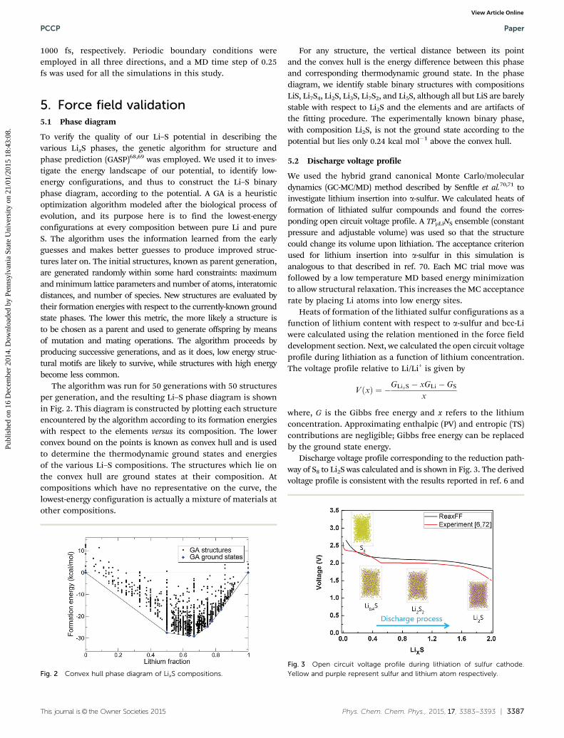
The algorithm was run for 50 generations with 50 structuresper generation, and the resulting Li–S phase diagram is shownin Fig. 2. This diagram is constructed by plotting each structureencountered by the algorithm according to its formation energieswith respect to the elements versus its composition. The lowerconvex bound on the points is known as convex hull and is usedto determine the thermodynamic ground states and energiesof the various Li–S compositions. The structures which lie onthe convex hull are ground states at their composition. Atcompositions which have no representative on the curve, thelowest-energy configuration is actually a mixture of materials atother compositions.
For any structure, the vertical distance between its pointand the convex hull is the energy difference between this phaseand corresponding thermodynamic ground state. In the phasediagram, we identify stable binary structures with compositionsLiS, Li7S4, Li2S, Li3S, Li7S2, and Li5S, although all but LiS are barelystable with respect to Li2S and the elements and are artifacts ofthe fitting procedure. The experimentally known binary phase,with composition Li2S, is not the ground state according to thepotential but lies only 0.24 kcal mol�1 above the convex hull.
5.2 Discharge voltage profile
We used the hybrid grand canonical Monte Carlo/moleculardynamics (GC-MC/MD) method described by Senftle et al.70,71 toinvestigate lithium insertion into a-sulfur. We calculated heats offormation of lithiated sulfur compounds and found the corres-ponding open circuit voltage profile. A TPmLiNS ensemble (constantpressure and adjustable volume) was used so that the structurecould change its volume upon lithiation. The acceptance criterionused for lithium insertion into a-sulfur in this simulation isanalogous to that described in ref. 70. Each MC trial move wasfollowed by a low temperature MD based energy minimizationto allow structural relaxation. This increases the MC acceptancerate by placing Li atoms into low energy sites.
Heats of formation of the lithiated sulfur configurations as afunction of lithium content with respect to a-sulfur and bcc-Liwere calculated using the relation mentioned in the force fielddevelopment section. Next, we calculated the open circuit voltageprofile during lithiation as a function of lithium concentration.The voltage profile relative to Li/Li+ is given by
VðxÞ ¼ �GLixS � xGLi � GS
x
where, G is the Gibbs free energy and x refers to the lithiumconcentration. Approximating enthalpic (PV) and entropic (TS)contributions are negligible; Gibbs free energy can be replacedby the ground state energy.
Discharge voltage profile corresponding to the reduction path-way of S8 to Li2S was calculated and is shown in Fig. 3. The derivedvoltage profile is consistent with the results reported in ref. 6 and
Fig. 2 Convex hull phase diagram of LixS compositions.Fig. 3 Open circuit voltage profile during lithiation of sulfur cathode.Yellow and purple represent sulfur and lithium atom respectively.
72. Likewise, the experimental observation, ReaxFF calculationsnicely predict the initial drop in the voltage profile due to theformation of high molecular weight polysulfides and the flatterregion and subsequent drop in the voltage approaching Li2S.
5.3 Volumetric expansion of LixS compounds
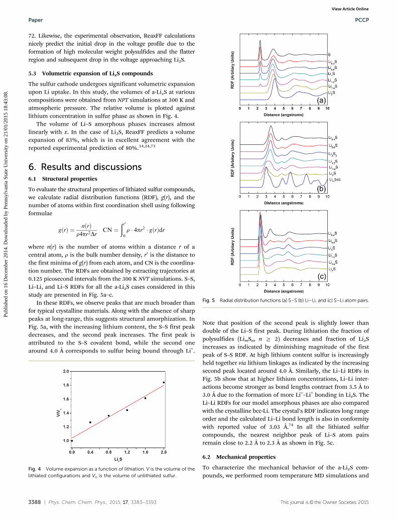
The sulfur cathode undergoes significant volumetric expansionupon Li uptake. In this study, the volumes of a-LixS at variouscompositions were obtained from NPT simulations at 300 K andatmospheric pressure. The relative volume is plotted againstlithium concentration in sulfur phase as shown in Fig. 4.
The volume of Li–S amorphous phases increases almostlinearly with x. In the case of Li2S, ReaxFF predicts a volumeexpansion of 83%, which is in excellent agreement with thereported experimental prediction of 80%.14,24,73
6. Results and discussions6.1 Structural properties
To evaluate the structural properties of lithiated sulfur compounds,we calculate radial distribution functions (RDF), g(r), and thenumber of atoms within first coordination shell using followingformulae
gðrÞ ¼ nðrÞr4pr2Dr
CN ¼ðr00
r � 4pr2 � gðrÞdr
where n(r) is the number of atoms within a distance r of acentral atom, r is the bulk number density, r0 is the distance tothe first minima of g(r) from each atom, and CN is the coordina-tion number. The RDFs are obtained by extracting trajectories at0.125 picosecond intervals from the 300 K NVT simulations. S–S,Li–Li, and Li–S RDFs for all the a-LixS cases considered in thisstudy are presented in Fig. 5a–c.
In these RDFs, we observe peaks that are much broader thanfor typical crystalline materials. Along with the absence of sharppeaks at long-range, this suggests structural amorphization. InFig. 5a, with the increasing lithium content, the S–S first peakdecreases, and the second peak increases. The first peak isattributed to the S–S covalent bond, while the second onearound 4.0 Å corresponds to sulfur being bound through Li+.
Note that position of the second peak is slightly lower thandouble of the Li–S first peak. During lithiation the fraction ofpolysulfides (LimSn, n Z 2) decreases and fraction of LixSincreases as indicated by diminishing magnitude of the firstpeak of S–S RDF. At high lithium content sulfur is increasinglyheld together via lithium linkages as indicated by the increasingsecond peak located around 4.0 Å. Similarly, the Li–Li RDFs inFig. 5b show that at higher lithium concentrations, Li–Li inter-actions become stronger as bond lengths contract from 3.5 Å to3.0 Å due to the formation of more Li+–Li+ bonding in LixS. TheLi–Li RDFs for our model amorphous phases are also comparedwith the crystalline bcc-Li. The crystal’s RDF indicates long rangeorder and the calculated Li–Li bond length is also in conformitywith reported value of 3.03 Å.74 In all the lithiated sulfurcompounds, the nearest neighbor peak of Li–S atom pairsremain close to 2.2 Å to 2.3 Å as shown in Fig. 5c.
6.2 Mechanical properties
To characterize the mechanical behavior of the a-LixS com-pounds, we performed room temperature MD simulations and
Fig. 4 Volume expansion as a function of lithiation. V is the volume of thelithiated configurations and Vo is the volume of unlithiated sulfur.
Fig. 5 Radial distribution functions (a) S–S (b) Li–Li, and (c) S–Li atom pairs.
obtained the stress–strain relationship under uniaxial tensileloading. We considered five different uniaxial strain rates(1 � 108, 5 � 108, 1 � 109, 1 � 1010, 1 � 1011 s�1) to investigatethe effect of strain rate on the mechanical properties. Stressesare calculated based on the definition of virial stress, which isexpressed as
svirialðrÞ ¼1
O
Xi
�mi _ui � _ui þ1
2
Xjai
rij � fij
!" #
where the summation is over all the atoms occupying the totalvolume, mi is the mass of atom i, is the time derivative whichindicates the displacement of atom with respect to a referenceposition, where is the position vector of atom, is the cross product,and is the interatomic force applied on atom i by atom j.
Fig. 6a–c shows tensile stress–strain curves at three strainrates for all the lithiated sulfur cases considered in this work.Stress–strain curves for the strain rate of 5� 108 and 1� 108 (s�1)are provided in the Fig. S1 of the ESI.† At lower strain rates, pastthe elastic limit, stress rises and drops repeatedly with thestrain, while under faster loading, no such fluctuations areobserved. Similar trends in the stress–strain curve at otherstrain rates have been observed in amorphous Ni-nanowiredeformation simulations.75 The zigzag stress–strain curve afterthe elastic limit at lower strain rate and higher lithiation casesare due to the stress-relaxation during tensile loading. At astrain rate of 1011 s�1, the maximum stress occurs at B15%strain. However, at a lower strain rate, it shifts to B10% strain.In general, stress–strain curves exhibit an initial linear region
followed by a nonlinear portion and then a drop in stress. Thelinear portion of the uniaxial stress–strain curve corresponds toelastic deformation and the gradient of this part is Young’smodulus (YM). In this study, YM was calculated using linearregression on the initial linear portion. The yield strength wascomputed by plotting a line parallel to the linear part of thestress–strain curve at 0.2 percent strain offset. The intersectionbetween this 0.2 percent offset line and stress–strain curvegives the yield strength. The ultimate strength is the maximumstress experienced during tensile loading. Effect of strain-rateon various mechanical properties and the lithiation-inducedvariation in strength for the a-LixS cases are presented in Fig. 6d–f.We see that the strain-rate has significant consequences for all ofthe material properties. During tensile loading, the combinationof both elastic and anelastic (time-dependent, fully reversibledeformation) strains determine the mechanical behavior ofthe materials.
At higher loading rates, anelastic strain approaches zeroresulting in entirely elastic strain, while at low-strain-rates bothof them accompany the loading process that contributes to thelower strength.76 Moreover, increases in strain rate enhance theflow stress that directly influences the mechanical behavior.The calculated Young’s modulus, ultimate strength, and yieldstrength at low-strain-rate are lower than that at high-strain-rates. This trend is consistent with the experimental observa-tions for amorphous materials.77 It can be seen from Fig. 6d–fthat strain rate converges at 1 � 1010 s�1 and the reportedstrength and YM values are in close proximity for the strain rateof 1 � 1010 (s�1) and lower. The calculated YM value for Li2S is
Fig. 6 Stress–strain curve for the a-LixS compositions at different strain rate (a) 1 � 109 s�1 (b) 1 � 1010 s�1, and (c) 1 � 1011 s�1; other mechanicalproperties (d) ultimate strength (e) yield strength, and (f) Young’s modulus; inset of (d) shows the convergence in the ultimate strength with the strain ratefor the case of Li1.6S.
B45 GPa, which is lower than the previously reported78 DFT-GGA results of 76.6 GPa, the discrepancy is likely due to theabsence of thermal effects in DFT optimization. However,extrapolation of the Young modulus of the dense hot pressedLi2S–P2S5 pellets to 100% Li2S composition would yield valuesaround 35 GPa, which is in excellent agreement with theReaxFF predictions.79
It is evident that lithiated sulfur compounds undergo strainhardening with increasing lithium concentration. Lithiation alsoaugments toughness and ductility of the lithiated compounds.Toughness is the amount of energy absorbed by a material beforeits failure. We observe that improvement in material strength israpid during initial lithiation, but beyond Li1.2S strengthening isnot substantial. During initial lithium loading, Li–S bonds areformed through the cleavage of S–S bonds. This contributes tothe increase in strength, while at higher lithium content, Li–Libond formation contributes to the strength increment to a lesserextent. Interestingly, the lithiation induced mechanical responseof the a-LixS compounds is quite opposite of that observed for thea-LixSi alloys. Lithiation degrades the mechanical properties ofsilicon,10,80 while in case of sulfur, it enhances the strength of thematerial. Lithiation of Si causes breaking of Si–Si bonds andsubsequent formation of the Li–Si bonds. The softening effectdue to the lithium insertion into the Si is attributed to thedecrease in the number of strong covalent Si–Si bonds as theybreaks and replaced by the weaker ionic Li–Si bonds. Shenoyet al.81 reported the elastic moduli of the amorphous-Si and Li are92 and 20 GPa, respectively. Our ReaxFF calculations predict theelastic moduli of Li and S as 23 and 5.78 GPa, respectively.Therefore, insertion of the Li into the softer S resulting in theincrease of the strength of LixS compositions.
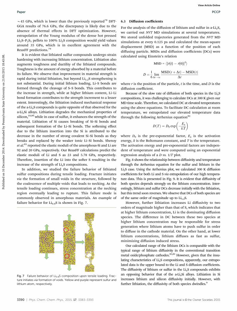
In addition, we studied the failure behavior of lithiatedsulfur compositions during tensile loading. Fracture initiatesvia the formation of small voids in the structure, followed bythe coalescence of multiple voids that leads to necking. As thetensile loading continues, stress concentration at the neckingregion eventually leading to rupture. This failure mode iscommonly observed in amorphous materials. An example offailure behavior for Li0.8S is shown in Fig. 7.
6.3 Diffusion coefficients
For the analysis of the diffusion of lithium and sulfur in a-LixS,we carried out NVT MD simulations at several temperatures.We stored unfolded trajectories generated from the NVT MDsimulations at every 0.125 ps and calculated the mean-squaredisplacement (MSD) as a function of the position of eachdiffusing particle. MSDs and diffusion coefficients (DCs) werecalculated using Einstein’s relation
MSD = h|r(t) � r(0)|2i
D ¼ 1
6lim
Dt!1
MSDðtþ DtÞ �MSDðtÞDt
where r is the position of the particle, t is the time, and D is thediffusion coefficient.
Because of the slow rate of diffusion of both species in the LixScompositions, it was challenging to calculate DCs at 300 K given ourMD time scale. Therefore, we calculated DC at elevated temperaturesusing the above equations. To facilitate DC calculation at roomtemperature, we extrapolated our elevated temperature datathrough the following Arrhenius equation82
DðTÞ ¼ D0 exp �Ea
kT
� �
where D0 is the pre-exponential factor, Ea is the activationenergy, k is the Boltzmann constant, and T is the temperature.The activation energy and pre-exponential factors are indepen-dent of temperature and were computed using an exponentialregression analysis of a D vs. 1/T plot.
Fig. 8 shows the relationship between diffusivity and temperaturethrough the Arrhenius equation for the sulfur and lithium in theLi2S case. Using the Arrhenius plot, we calculated 300 K diffusioncoefficients for both Li and S via extrapolation of our high tempera-ture data. This is presented in Fig. 9. It is evident that diffusivity ofboth species depends strongly on the lithium concentration. Inter-estingly, lithium and sulfur DCs decrease initially with the lithiation,but this trend soon reverses. We observe that DCs of both species areof the same order of magnitude up to Li1.2S.
However, further lithiation increases Li diffusivity to twoorders of magnitude higher than that of S, which indicates thatat higher lithium concentration, Li is the dominating diffusionspecies. The difference in DC between these two species athigher lithium concentration may be responsible for stressgeneration where lithium atoms have to push sulfur in orderto diffuse in the cathode material. On the other hand, at lowerlithium concentrations, lithium diffuses as fast as sulfur,minimizing diffusion induced stress.
Our calculated range of the lithium DCs is comparable with thetypical range of lithium diffusivity in the conventional transitionmetal oxide/phosphate cathodes.83,84 However, given that the insu-lating characteristics of LixS compositions, apparently, our extrapo-lated data is the upper bound to the Li and S diffusion coefficients.The diffusivity of lithium or sulfur in the LixS compounds exhibitsan opposing behavior that of the a-LixSi alloys. Lithiation in Siincreases lithium and silicon diffusivity initially. However, withfurther lithiation, the diffusivity of both species dwindles.9
Fig. 7 Failure behavior of Li0.8S composition upon tensile loading. Frac-ture initiates via formation of voids. Yellow and purple represent sulfur andlithium atom, respectively.
We developed a ReaxFF potential for describing Li–S interactionsand performed MD simulations to study various structural,mechanical, and diffusion properties in a-LixS compounds.ReaxFF reproduces the experimental open circuit voltage profileduring cell discharge. The volume expansion of the a-LixScompositions captured in our simulations matches experimentalobservations well. The phase diagram produced by a GA searchof the potential provides information about the formationenergies of the various LixS phases as a function of composition.GA scheme exhibits that experimentally known Li2S structurelies in a very close proximity of the convex hull, i.e. ground state.Our simulations for calculating mechanical properties of a-LixSillustrate that lithiated sulfur compounds undergo strain hard-ening with lithiation, which results in an increase in strengthand toughness. Dependence of the mechanical properties ofa-LixS compounds on strain rate is observed: the material exhibitshigher strength with increasing strain rate. Young modulus fromour calculations was found in good agreement with the extrapolatedexperimental values. Diffusion coefficients of both lithium andsulfur are contingent on the lithium content in a-LixS composi-tions. These demonstrate that the developed Li–S potential canaccurately describe Li–S chemistry.
This newly developed Li–S potential and its application tolithiated sulfur systems provides a new perspective on lithiationinduced mechanical responses of sulfur cathodes at the mostfundamental atomistic level. The computed material propertieswill enable the development of a continuum model to furtherinvestigate the morphological evolution, degradation, and failuremechanism of lithiated sulfur during electrochemical cycling forspecimens of experimental length and time scale. We believethese atomistic-level insights will play a vital role in designingcathode materials for high performance Li–S batteries to meetfuture energy demand.
Acknowledgements
This work was supported by the grant from the US ArmyResearch Laboratory through the Collaborative Research Alliance(CRA) for Multi Scale Multidisciplinary Modeling of ElectronicMaterials (MSME) and DoD High Performance Computing (HPC)Productivity Enhancement, Technology Transfer, and Training(PETTT) Program contract number PP-CCM-KY03-005-P3.
Notes and references
1 J.-M. Tarascon and M. Armand, Nature, 2001, 414, 359–367.2 M. S. Whittingham, Chem. Rev., 2004, 104, 4271–4302.3 M. Nagao, Y. Imade, H. Narisawa, T. Kobayashi, R. Watanabe,
T. Yokoi, T. Tatsumi and R. Kanno, J. Power Sources, 2013,222, 237–242.
4 M.-K. Song, S. Park, F. M. Alamgir, J. Cho and M. Liu, Mater.Sci. Eng., R, 2011, 72, 203–252.
5 M.-K. Song, E. J. Cairns and Y. Zhang, Nanoscale, 2013, 5,2186–2204.
Fig. 8 Arrhenius plot for calculating diffusion coefficient at 300 K, (a)sulfur, and (b) lithium.
Fig. 9 Diffusion coefficient of (a) sulfur, and (b) lithium at 300 K, calcu-lated using Arrhenius relation.
6 X. Ji, K. T. Lee and L. F. Nazar, Nat. Mater., 2009, 8, 500–506.7 J. Shim, K. A. Striebel and E. J. Cairns, J. Electrochem. Soc.,
2002, 149, A1321–A1325.8 M. K. Y. Chan, C. Wolverton and J. P. Greeley, J. Am. Chem.
Soc., 2012, 134, 14362–14374.9 Z. Cui, F. Gao, Z. Cui and J. Qu, J. Power Sources, 2012, 207,
150–159.10 K. Zhao, G. Tritsaris, M. Pharr, W. Wang, O. Okeke, Z. Suo,
J. Vlassak and E. Kaxiras, Nano Lett., 2012, 12, 4397–4403.11 B. Scrosati and J. Garche, J. Power Sources, 2010, 195,
2419–2430.12 F. Fan, S. Huang, H. Yang, M. Raju, D. Datta, V. B. Shenoy,
A. C. T. van Duin, S. Zhang and T. Zhu, Modell. Simul. Mater.Sci. Eng., 2013, 21, 074002.
13 C.-Y. Chou, H. Kim and G. S. Hwang, J. Phys. Chem. C, 2011,115, 20018–20026.
14 G. Zheng, Y. Yang, J. J. Cha, S. S. Hong and Y. Cui, NanoLett., 2011, 11, 4462–4467.
15 L. Ji, M. Rao, H. Zheng, L. Zhang, Y. Li, W. Duan, J. Guo,E. J. Cairns and Y. Zhang, J. Am. Chem. Soc., 2011, 133,18522–18525.
16 Y. Yang, M. T. McDowell, A. Jackson, J. J. Cha, S. S. Hongand Y. Cui, Nano Lett., 2010, 10, 1486–1491.
17 S. S. Zhang, J. Power Sources, 2013, 231, 153–162.18 L. Chen and L. L. Shaw, J. Power Sources, 2014, 267, 770–783.19 X. He, J. Ren, L. Wang, W. Pu, C. Jiang and C. Wan, J. Power
Sources, 2009, 190, 154–156.20 Y.-X. Yin, S. Xin, Y.-G. Guo and L.-J. Wan, Angew. Chem., Int.
Ed., 2013, 52, 13186–13200.21 L. Yuan, H. Yuan, X. Qiu, L. Chen and W. Zhu, J. Power
Sources, 2009, 189, 1141–1146.22 F. Wu, A. Magasinski and G. Yushin, J. Mater. Chem. A, 2014,
2, 6064–6070.23 H. Wang, Y. Yang, Y. Liang, J. T. Robinson, Y. Li, A. Jackson,
Y. Cui and H. Dai, Nano Lett., 2011, 11, 2644–2647.24 F. Zhang, X. Zhang, Y. Dong and L. Wang, J. Mater. Chem.,
2012, 22, 11452–11454.25 M. Barghamadi, A. Kapoor and C. Wen, J. Electrochem. Soc.,
2013, 160, A1256–A1263.26 J. Kim, D.-J. Lee, H.-G. Jung, Y.-K. Sun, J. Hassoun and
B. Scrosati, Adv. Funct. Mater., 2013, 23, 1076–1080.27 D.-R. Chang, S.-H. Lee, S.-W. Kim and H.-T. Kim, J. Power
Sources, 2002, 112, 452–460.28 J. Hassoun, J. Kim, D.-J. Lee, H.-G. Jung, S.-M. Lee, Y.-K. Sun
and B. Scrosati, J. Power Sources, 2012, 202, 308–313.29 H. Wang, W.-D. Zhang, Z.-Q. Deng and M.-C. Chen, Solid
State Ionics, 2009, 180, 212–215.30 T. Osaka, T. Momma, Y. Matsumoto and Y. Uchida,
J. Electrochem. Soc., 1997, 144, 1709–1713.31 N. J. Dudney, J. Power Sources, 2000, 89, 176–179.32 X. Liang, Z. Wen, Y. Liu, M. Wu, J. Jin, H. Zhang and X. Wu,
J. Power Sources, 2011, 196, 9839–9843.33 K. Nishikawa, Y. Fukunaka, T. Sakka, Y. H. Ogata and
J. R. Selman, J. Electrochem. Soc., 2007, 154, A943–A948.34 N. Liu, L. Hu, M. T. McDowell, A. Jackson and Y. Cui,
ACS Nano, 2011, 5, 6487–6493.
35 Y. Yang, G. Zheng, S. Misra, J. Nelson, M. F. Toney andY. Cui, J. Am. Chem. Soc., 2012, 134, 15387–15394.
36 K. Cai, M.-K. Song, E. J. Cairns and Y. Zhang, Nano Lett.,2012, 12, 6474–6479.
37 X. He, J. Ren, L. Wang, W. Pu, C. Wan and C. Jiang, Ionics,2009, 15, 477–481.
38 C. R. Jarvis, M. J. Lain, M. V. Yakovleva and Y. Gao, J. PowerSources, 2006, 162, 800–802.
39 M. M. Islam, V. S. Bryantsev and A. C. T. van Duin,J. Electrochem. Soc., 2014, 161, E3009–E3014.
40 J. Tersoff, Phys. Rev. Lett., 1988, 61, 2879–2882.41 D. W. Brenner, Phys. Rev. B: Condens. Matter Mater. Phys.,
1990, 42, 9458–9471.42 T. Liang, Y. K. Shin, Y.-T. Cheng, D. E. Yilmaz, K. G. Vishnu,
O. Verners, C. Zou, S. R. Phillpot, S. B. Sinnott andA. C. T. van Duin, Annu. Rev. Mater. Res., 2013, 43, 109–129.
43 A. C. van Duin, A. Strachan, S. Stewman, Q. Zhang, X. Xuand W. A. Goddard, J. Phys. Chem. A, 2003, 107, 3803–3811.
44 K. D. Nielson, A. C. van Duin, J. Oxgaard, W.-Q. Deng andW. A. Goddard, J. Phys. Chem. A, 2005, 109, 493–499.
45 W. J. Mortier, S. K. Ghosh and S. Shankar, J. Am. Chem. Soc.,1986, 108, 4315–4320.
46 A. C. van Duin, S. Dasgupta, F. Lorant and W. A. Goddard,J. Phys. Chem. A, 2001, 105, 9396–9409.
47 K. Chenoweth, A. C. T. van Duin and W. A. Goddard, J. Phys.Chem. A, 2008, 112, 1040–1053.
48 M. F. Russo Jr and A. C. T. van Duin, Nucl. Instrum. MethodsPhys. Res., Sect. B, 2011, 269, 1549–1554.
49 D. Bedrov, G. D. Smith and A. C. van Duin, J. Phys. Chem. A,2012, 116, 2978–2985.
50 F. Castro-Marcano, A. M. Kamat, M. F. Russo Jr, A. C. van Duinand J. P. Mathews, Combust. Flame, 2012, 159, 1272–1285.
51 A. C. T. van Duin, J. M. A. Baas and B. van de Graaf, J. Chem.Soc., Faraday Trans., 1994, 90, 2881.
52 M. W. Schmidt, K. K. Baldridge, J. A. Boatz, S. T. Elbert,M. S. Gordon, J. H. Jensen, S. Koseki, N. Matsunaga,K. A. Nguyen and S. Su, et al., J. Comput. Chem., 1993, 14,1347–1363.
53 M. Head-Gordon, J. A. Pople and M. J. Frisch, Chem. Phys.Lett., 1988, 153, 503–506.
54 A. I. Boldyrev, J. Simons and P. von R. Schleyer, J. Chem.Phys., 1993, 99, 8793.
55 M. W. Wong, Y. Steudel and R. Steudel, Chem. Phys. Lett.,2002, 364, 387–392.
56 P. Hohenberg and W. Kohn, Phys. Rev., 1964, 136, B864.57 W. Kohn and L. J. Sham, Phys. Rev., 1965, 140, A1133.58 G. Kresse and J. Hafner, Phys. Rev. B: Condens. Matter Mater.
Phys., 1993, 48, 13115.59 G. Kresse and J. Furthmuller, Phys. Rev. B: Condens. Matter
Mater. Phys., 1996, 54, 11169.60 P. E. Blochl, Phys. Rev. B: Condens. Matter Mater. Phys., 1994,
50, 17953.61 J. P. Perdew, K. Burke and M. Ernzerhof, Phys. Rev. Lett.,
1996, 77, 3865–3868.62 E. Zintl, A. Harder and B. Dauth, Z. Elektrochem. Angew.
69 W. W. Tipton and R. G. Hennig, J. Phys.: Condens. Matter,2013, 25, 495401.
70 T. Senftle, M. Janik and A. C. T. van Duin, J. Phys. Chem. C,2014, 118, 4967–4981.
71 T. P. Senftle, R. J. Meyer, M. J. Janik and A. C. T. van Duin,J. Chem. Phys., 2013, 139, 044109.
72 P. G. Bruce, S. A. Freunberger, L. J. Hardwick and J.-M.Tarascon, Nat. Mater., 2012, 11, 19–29.
73 H. Chen, W. Dong, J. Ge, C. Wang, X. Wu, W. Lu andL. Chen, Sci. Rep., 2013, 3, 1910.
74 L. E. Sutton, Tables of Interatomic Distances and Configu-ration in Molecules and Ions: Supplement 1956–1959,Chemical Society, 1965.
75 P. S. Branıcio and J.-P. Rino, Phys. Rev. B: Condens. MatterMater. Phys., 2000, 62, 16950.
76 J. R. Davis, Tensile Testing, ASM International, 2004.77 M. L. Falk and J. S. Langer, 2010, arXiv10044684.78 H. Khachai, R. Khenata, A. Bouhemadou, A. H. Reshak,
A. Haddou, M. Rabah and B. Soudini, Solid State Commun.,2008, 147, 178–182.
79 A. Sakuda, A. Hayashi and M. Tatsumisago, Sci. Rep., 2013,3, 2261.
80 K. Zhao, W. L. Wang, J. Gregoire, M. Pharr, Z. Suo,J. J. Vlassak and E. Kaxiras, Nano Lett., 2011, 11, 2962–2967.
81 V. B. Shenoy, P. Johari and Y. Qi, J. Power Sources, 2010, 195,6825–6830.
82 A. C. van Duin, B. V. Merinov, S. S. Han, C. O. Dorso andW. A. Goddard Iii, J. Phys. Chem. A, 2008, 112, 11414–11422.
83 S. Franger, F. L. Cras, C. Bourbon and H. Rouault, Electro-chem. Solid-State Lett., 2002, 5, A231–A233.
84 L.-X. Yuan, Z.-H. Wang, W.-X. Zhang, X.-L. Hu, J.-T. Chen,Y.-H. Huang and J. B. Goodenough, Energy Environ. Sci.,2011, 4, 269–284.