Receiver Architectures ELT-44007/RxArch/1 M. Renfors, TUT/ELT/WICO 06.09.16 Receiver Architectures Markku Renfors Department of Electronics and Communications Engineering Tampere University of Technology, Finland [email protected]
· Amplifiers- Low-noise amplifiers (LNAs) in the first stages.
- Automatic gain control (AGC) needed to cope with different signal levels.
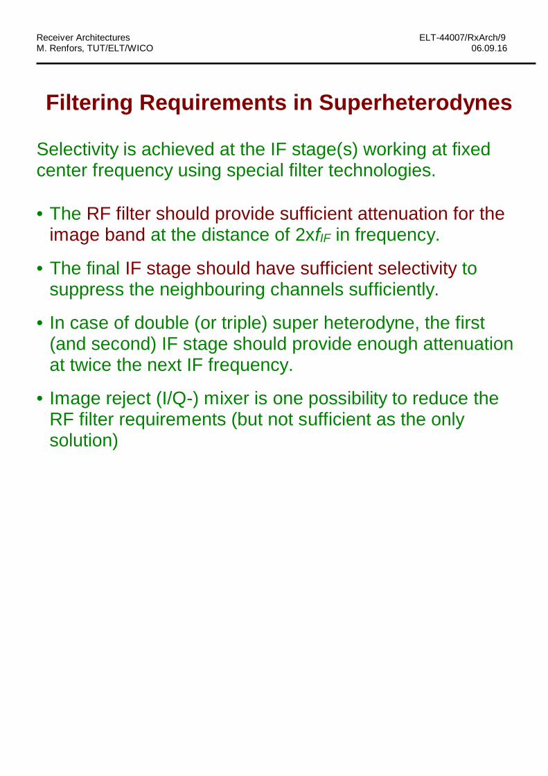
· Filters- Impossible to achieve sufficient selectivity by tunable RF filters (operating in the RF frequency band of the modulated signal) to separate the desired signal from others.
- Sufficient selectivity can be achieved by fixed (RF or IF) filters based on special technologies (SAW, Surface Acoustic Wave, ceramic, crystal, mechanical)
or active analog filters operating on basedband or low bandpass center frequencies
or multirate digital filters up to some hundreds of MHz range.
· Filters (continued) - Special complex filters, phase splitters (related also to Hilbert transformers) can be used to suppress certain frequency range from the negative part of the frequency axis. Such filters find application in certain special receiver architectures.
- Real bandpass signal and the corresponding ideal analyticbandpass signal (obtained ideally through Hilberttransform):
- Other side of the desired signal spectrum suppressed by apractical phase splitter with finite attenuation:
· Oscillators- Voltage (or current or digitally) controlled oscillators
(VCO, ICO, DCO) are used to generate the localoscillator (LO) signals in a tunable manner.
- In a communications transceiver (receiver+transmitter,RX+TX), the frequency synthesizer is one of the mainblocks. It is used for generating all the needed LOsignals in a controllable manner.
· Analog-to-digital interface- Various ADC technologies
- Key performance metrics:
o Number of bits / Dynamic range / SNR
o Sampling jitter effects
- Main bottleneck in advanced DSP-based architectures.
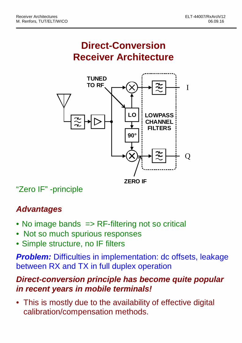
· No image bands => RF-filtering not so critical· Not so much spurious responses· Simple structure, no IF filtersProblem: Difficulties in implementation: dc offsets, leakagebetween RX and TX in full duplex operationDirect-conversion principle has become quite popularin recent years in mobile terminals!· This is mostly due to the availability of effective digital
Constant DC-offset can be compensated by measuring itwithout signal and then subtracting it during reception.
In TDMA systems, different channels/bursts may havedifferent signal levels and different AGC-values and hencedifferent DC-offsets => compensation is difficult.
Also 1/f -type of noise appearing in active components maybe a problem. This effect also appears at DC and lowfrequencies.
Other issues
Signal leakage from antenna to the surroundings takesplace more easily than in superhet.
Sensitivity to 2nd-order intermodulation is another drawbackthat will be discussed later.
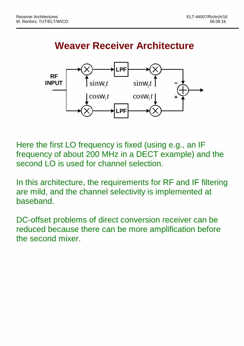
Low-IF Receiver ArchitectureThe idea is to use quadrature down-conversion and a low IFfrequency which is just high enough to cope with the DC-offsetproblem (e.g., 250 kHz in case of GSM).
f
f
-fIFA COMPLEXBANDPASSFILTER
-fLO
fIF0
0
The channel filtering and final quadrature down-conversion canbe done after A/D-conversion in the DSP domain.As we shall see on the next pages, quadrature down-conversionin the analog domain may not, in practice, provide sufficientattenuation for the image band.More attenuation can be obtained by using a phase splitterattenuating the image band on the negative part of the frequencyaxis.Even more attenuation could possibly be achieved throughbaseband digital signal processing.The low-IF concept is facilitated by the fact that systemspecifications (like GSM) don't allow the maximum signal level toappear in the nearest adjacent channels in case of a very lowdesired signal level.
In this architecture, the image is suppressed25 … 30 dB by the phase splitter implemented as apolyphase RC network, and another 25 … 30 dB bythe quadrature downconversion approach.
Image Rejection as a Function of Gain andPhase Imbalance
Assuming that g is the gain imbalance ratio and f is thephase difference due to imbalance, we can write:
( )( ) ( )
( ) ( ) cos sin
( )2 2
1 1( )2 2
c c c c
c c
c cj t j t j t j t
j jj t j t
y t x t t jg t
e e e ex t g
ge gex t e e
w w w f w f
f fw w
w w f
- + - +
--
= + +é ùë ûé ù+ -
= +ê úê úë ûé ù+ -
= +ê úê úë û
From the latter form, we can identify the strength of the twospectral components produced by the two frequencytranslations. The ratio of the image and desired signalpowers is obtained as
2
22
2 2
12 1 2 cos
1 2 cos12
j
j
geg gRg gge
f
f
f
f
--
+ -= =
+ ++
This result can be applied to all cases of quadrature mixingwhere gain and/or phase imbalance appears.
Frequency-Dependant Imbalance ModelEspecially in wide-band systems, the imbalance parametersmay be frequency dependant and can be written as g(f) andf(f).
Then also the image suppression ratio is frequency-dependant:
Effects of Gain and Phase ImbalanceIn case of direct conversion-receiver (or final demodulation of anI/Q-signal), gain mismatch and phase errors cause “self images”:
0f
0f
-fLO+fLO
This is usually not a problem with low-order modulations, forwhich an image attenuation of, e.g., 20 dB doesn’t essentiallyeffect the system performance. For high-order modulations, thisissue is more critical.
In other cases of quadrature down-conversion, like the low-IFreceiver, the image signal may be at a considerably stronger level(up to 100 dB!!) than the desired signal, and I/Q imbalance isvery critical:
Radio system specifications (e.g., for cellular systems) don'tallow a strong adjacent channel signal to be present when aweak desired signal is to be received. (Radio ResourceManagement functionalities of wireless systems take careof this!)
For example, the GSM specifications give:
· The maximum levels for the 3 adjacent channels on bothsides (at 200, 400 and 600 kHz from the carrier) in caseof a GSM interferer and desired signal 20 dB above thereference sensitivity level of -102 dBm.
· Maximum levels for more distant signals (>600 kHz fromcarrier), blocking signals, in case of a sinusoidal interfererand desired signal 3 dB above the reference sensitivitylevel.
PART 3Non-Idealities and Performance Metrics of the
Analog Front-End Modules
· Sensitivity of the receiver is mainly determined by thenoise produced by the receiver front-end components. Itdetermines the minimum detectable signal in noise-limited situation. In general:
where B is the equivalent noise bandwidth of the RX.
For example in GSM, minimum S/N is 9 dB, B=200 kHz,and required sensitivity is -102 dBm => NF<10 dB.
· With low received signal levels, the receiver front-endcomponents can be assumed to be linear. With highersignal levels, the nonlinearity of the amplifiers and othercomponents produce harmful intermodulation products.In this way the nonlinearity limits the dynamic range ofreceived signals from above.
Intermodulation is measured by 1 dB compression point or the so-called IP3 figure.
In RF circuit design, there are always tradeoffs betweennoise figure, linearity, and power consumption.
Non-Idealities and Performance Measures ofthe Analog Front-End Components (continued)
· Frequency accuracy and stability are determined bythe local oscillators of the receiver. In systems like GSM,the receiver is locked to the network, and the frequencystability is very good. However, to guarantee that thereceiver is able to synchronize to the network, certainfrequency accuracy, stability, and settling timerequirements are set for the components.
The short term instability of the oscillators appear asphase noise, and it is very critical for the RF performance
of the system.
· Leakage effect means that strong signals, especiallylocal oscillator signals are connected, e.g., throughspurious capacitances to places where they are notsupposed to be connected. This means that variousharmonics, subharmonics, and mixtures of the localoscillator frequencies are usually added to the signal.
In receiver design, the frequencies of the strongestspurious frequencies can be calculated. By selecting thelocal oscillator frequencies properly, most of the spuriousfrequencies can be placed outside the desired frequencybands at RF and IF.
· In the case of analog I/Q signal processing, amplitudeand phase responses of the I and Q branches are neverexactly the same. The effects of the gain and phaseimbalance depend greatly on the receiver architecture.
For a cascade of n stages, the overall noise factor is
121213
12
1111
-
-++
-+
-+=
nn
T gggF
ggF
gFFF
LL
where Fi and gi are the noise factor and power gain ofstage i .
This result can be easily derived using the previous results,since the contribution of each stage to the equivalent inputnoise source is
1 2 1
( 1)i th
i
F Ng g g -
-L
A passive component at the front-end (e.g., duplexer or RFfilter) doesn’t usually produce significant noise, but itsattenuation enhances the effects of the following noisyamplifier stages. The noise figure of a passive componentis equal to its attenuation in dB. This is because the thermalnoise is present both at the input and output, and the noisefactor can be written as:
IntermodulationConsider a test where there are two nearby frequencies f1 andf2 in the system frequency band (like in the neighbouringchannels).
In general, intermodulation produces new frequency components:
2211 fkfk +
where 1 2,k k are integers. The order of an intermodulation productis 1 2k k+ .
Third-order intermodulation produces (among some others)frequencies 1 2 2 12 , 2f f f f- - which may fall in the desired signalband.
f2f12f1-f2
f
Second-order intermodulation produces frequencies1 2 2 1,f f f f+ - .
In general, with low-enough signal levels, the levels of second-and third-order intermodulation products are proportional to the2nd and 3rd power of the fundamental signal level, respectively.
Low-order polynomial transfer characteristic can be used formodelling memoryless nonlinearities. For example, a third-ordermodel produces only second- and third-order intermodulation. Ifthe signal transfer characteristic is antisymmetric with respect toorigin, only odd-order terms appear in the polynomial model, andonly odd-order intermodulation products appear. Differentialanalog circuitry helps in this direction.
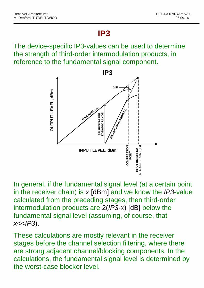
IP3The device-specific IP3-values can be used to determinethe strength of third-order intermodulation products, inreference to the fundamental signal component.
FUNDAMENTAL
SPUR
IOU
S-FR
EED
YNA
MIC
RAN
GE
3RD-
ORD
ERIM
PRO
DUCT
1dB
COM
PRES
SIO
NPO
INT
INPU
T-R
EFER
RED
INTE
RCEP
TPO
INT
(IP3)
INPUT LEVEL, dBm
OU
TPU
TLE
VEL
,dB
m
IP3
In general, if the fundamental signal level (at a certain pointin the receiver chain) is x [dBm] and we know the IP3-valuecalculated from the preceding stages, then third-orderintermodulation products are 2(IP3-x) [dB] below thefundamental signal level (assuming, of course, thatx<<IP3).
These calculations are mostly relevant in the receiverstages before the channel selection filtering, where thereare strong adjacent channel/blocking components. In thecalculations, the fundamental signal level is determined bythe worst-case blocker level.
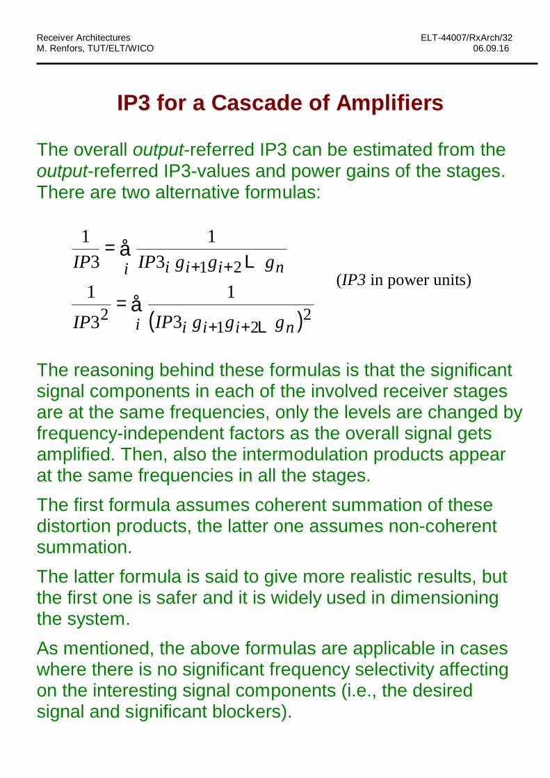
The overall output-referred IP3 can be estimated from theoutput-referred IP3-values and power gains of the stages.There are two alternative formulas:
( )å
å
++
++
=
=
i niii
i niii
gggIPIP
gggIPIP
221
2
21
31
3
13
13
1
L
L
(IP3 in power units)
The reasoning behind these formulas is that the significantsignal components in each of the involved receiver stagesare at the same frequencies, only the levels are changed byfrequency-independent factors as the overall signal getsamplified. Then, also the intermodulation products appearat the same frequencies in all the stages.The first formula assumes coherent summation of thesedistortion products, the latter one assumes non-coherentsummation.The latter formula is said to give more realistic results, butthe first one is safer and it is widely used in dimensioningthe system.As mentioned, the above formulas are applicable in caseswhere there is no significant frequency selectivity affectingon the interesting signal components (i.e., the desiredsignal and significant blockers).
As discussed below, 3rd-order intermodulation effects aresignificant in traditional superheterodyne receiver design,whereas 2nd-order intermodulation effects are less critical.However, with direct-conversion and low-IF receivers, also2nd-order effects are very important.
IP2 is defined in a similar way as IP3. In general, thesecond-order intermodulation products are (IP2-x) [dB]below the fundamental signal level x (assuming again thatx<<IP2). For amplifiers and other active components, theIP2 values are typically somewhat higher than the IP3values but, anyway, 2nd-order products tend to be strongerthan 3rd-order effects.
The overall output-referred IP2 can be estimated from theoutput-referred IP2-values and power gains of the stages.There are two alternative formulas:
1 2
1 2
1 12 2
1 12 2
i i i i n
i i i ni
IP IP g g g
IP IP g g g
+ +
+ +
=
=
å
åL
L(IP2 in power units)
Again, the first formula assumes coherent summation ofthese distortion products, the latter one assumes non-coherent summation.
For equal IP2 and IP3 values, 2nd-order intermodulationproducts are clearly stronger than 3rd-order products
=> If 2nd-order intermodulation products of some strong signals (blocking signals) appear on the signal band, then better linearity is required.
· In typical superheterodyne receivers, only 3rd-orderintermodulation is a problem, because signals causing2nd-order products on the signal band are attenuated bythe RF filter.
· In wideband superhet with relatively low IF, also the 2nd-order intermodulation may become a problem.
· 2nd-order intermodulation is always a problem in direct-conversion and low-IF receivers.
Non-Idealities in OscillatorsIn-band effects (i.e., they may exist even if no adjacentchannels and blockers are present):· Constant phase error rotates the constellation; This can be
corrected by baseband processing afterwards· Phase noise: random fluctuations in the instantaneous
phase/frequency of the oscillator cause random constellationrotations, reducing the noise margin and increasing BER:
0 1 2 3 4-1-2-3-4
0
-1
-2
-3
-4
1
2
3
4
I
Q
The RF effects of phase noise tend to be far more criticalthan in-band effects:· Mixing products of the phase noise spectrum and strong
adjacent channel signals (reciprocal mixing) may producespurious signals which overlap the desired signal. The followingfigure shows the noisy LO spectrum, RF-spectrum, andspectrum after mixing with practical LO with phase noise.
· wanted signal -102 dBm + 3 dB = -99 dBm· blocking signal -43 dBm @ 600 kHz· Minimum S/N=9 dB· Noise bandwidth 200 kHz
Assume that the phase noise spectrum is flat within thenoise bandwidth with x dBc/Hz (i.e., the noise power in 1Hz bandwidth is x dB in reference to the power of the VCOat the LO frequency)
ð noise power at noise bandwidth: -43 dBm+x+10 log10 200000 < -99 - 9 dBm
[2] L.E. Larson (Ed.), RF and Microwave Circuit Design for Wireless Communications. ArtechHouse 1996. (Chapters 2 and 3)
[2a] J.Y.C. Cheah, "Introduction to wireless communications applications and circuitdesign," pp. 17-41.
[2b] A.A. Abidi, "Low-power radio-frequency ICs for portable communications," pp. 43-98.(Also in Proc. IEEE, April 1995.)
[3] C. Chien, Digital Radio Systems on a Chip, A Systems Approach. Kluwer 2001.
[4] S. Sheng, R. Brodersen, Low-Power CMOS Wireless Communications - A Wideband CDMASystem Design. Kluwer 1998.
[5] B. Razavi, "Architecture and circuits for RF CMOS receivers," in Proc. IEEE 1998 CustomIntegrated Circuits Conference, pp. 393-400.
[6] B. Razavi, "Challenges in portable RF transceiver design," IEEE Circuits and DevicesMagazine, Sept. 1996, pp. 12-25.
[7] B. Razavi, "Design considerations for direct-conversion receivers, " IEEE Trans Circuits Syst. -II, vol. 44, pp. 428-435, June 1997.
[8] J. Crols, M. Steyaert, CMOS Wireless Transceiver Design. Kluwer 1997.
[9] J. Crols, M.S. Steyaert, "Low-IF topologies for high-performance analog front ends of fullyintegrated receievrs," IEEE Trans Circuits Syst. -II, vol. 45, pp. 269-282, March 1998.
[10] A. Loke, F. Ali, "Direct conversion radio for digital mobile phones - Design issues, status, andtrends," IEEE Trans. Microwave Theory and Techniques, vol 50, no. 11, pp. 2422-2435, Nov.2002.
[11] P.-I. Mak, S.-P U, and R. P. Martins, “Transceiver architecture selection: Review, State-of-the-Art Survey and Case Study”, IEEE Circuits and Systems Magazine, vol. 7, 2nd quarter 2007, pp. 6-25.