21
SISTEM KOMUNIKASI RECEIVER FM & AGC: Superheterodyne, Demodulator FM, FM Stereo, AGC

SISTEM KOMUNIKASI
RECEIVER FM & AGC: Superheterodyne, Demodulator FM,
FM Stereo, AGC

FM receiver
FM receiver is similar to the superheterodyning
(down converting) layout:
BPF-RF
mixer
LO
BPF-IF limiter Discrimi-
nator
Detektor
selubung
DC
Blocking
SFM(t)-IF S’FM(t)-IF
A
A’
B
C D

Up Converter (di Pemancar)
Filter
BPF-RF
MIXER
OSCILLATOR
RF IF
fosc
fosc—IF
fosc+IF

Down Converter (di Penerima)
Filter
BPF-IF
MIXER
OSCILLATOR
IF RF
fosc
fosc — RF
fosc + RF

Limiter
A limiter is a circuit whose output is constant
for all input amplitudes above a threshold
Limiter’s function in an FM receiver is to
remove unwanted amplitude variations of the
FM signal
Limiter

Demodulasi Sinyal FM
Dengan menggunakan diskriminator/differensiator
Pada sinyal FM, informasi terkandung pada frekuensi sinyal
FM
Jika dilakukan diferensiasi terhadap SFM(t) (keluaran
discriminator) didapat :
t
fIFcFM dttmktfAtS0
)(22cos
t
fIFfIFcFM dttmktftmkfAtS )(22sin22'
Informasi terkandung pada bagian selubung dari S’FM(t)
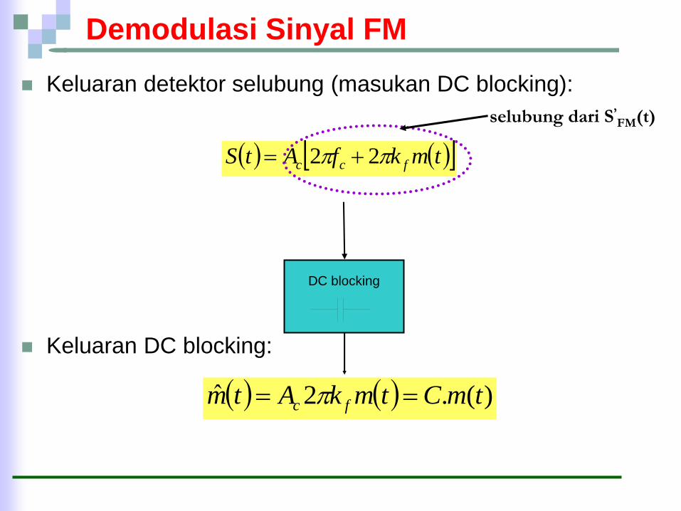
Demodulasi Sinyal FM
Keluaran detektor selubung (masukan DC blocking):
Keluaran DC blocking:
)(.2ˆ tmCtmkAtm fc
tmkfAtS fcc 22
selubung dari S’FM(t)
DC blocking

Discriminator
The heart of FM is this relationship
What we need is a device that linearly
follows inst. frequency
fi(t)=fc+kfm(t)
Disc.output
f
Deviation limits
+75 KHz -75 KHz
fcarrier
fcarrier is at the IF frequency
Of 10.7 MHz

Examples of discriminators
Slope detector - simple LC tank circuit
operated at its most linear response curve
This setup turns an FM signal
into an AM
fc fo
output
f
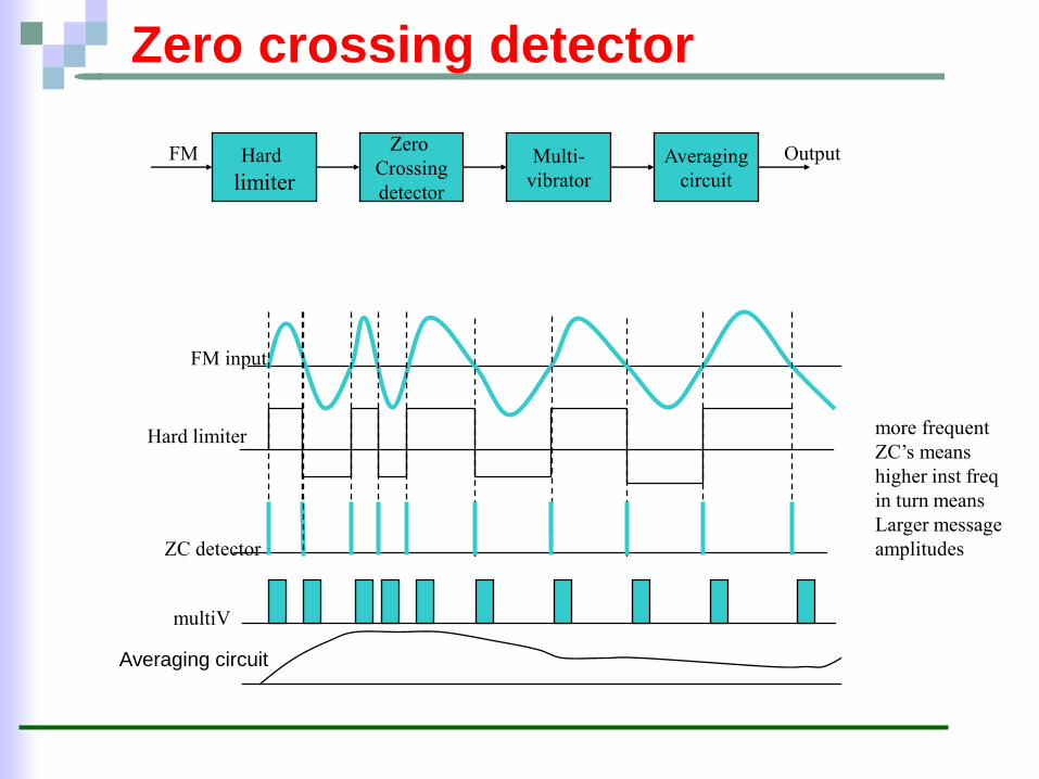
Zero crossing detector
Hard
limiter
Zero
Crossing
detector
Multi-
vibrator
Averaging
circuit
FM Output
FM input
Hard limiter
ZC detector
multiV
more frequent
ZC’s means
higher inst freq
in turn means
Larger message
amplitudes
Averaging circuit

Commercial FM
Commercial FM broadcasting uses the
following parameters
Baseband:15KHz = W = fm
Deviation ratio:5 (index modulasi)
Peak freq. Deviation=75KHz
BFM=2(+1)W=2x6x15=180KHz

Commercial FM spectrum
The FM landscape looks like this
FM station B FM station A FM station C
25KHz guardband
150 KHz
200 KHz
carrier
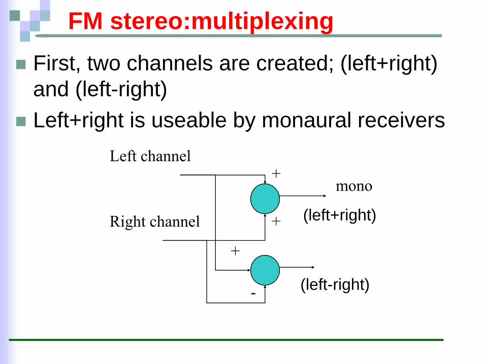
FM stereo:multiplexing
First, two channels are created; (left+right)
and (left-right)
Left+right is useable by monaural receivers
-
Left channel
Right channel
+
+
+
mono
(left+right)
(left-right)

Subcarrier modulation
The mono signal is left alone but the
difference channel is amplitude modulated
with a 38 KHz carrier
Left channel
Right channel
+
+
+
mono
DSB-SC
fsc=38 kHz
+
fsc=
38KHz
freq
divider
Composite baseband
-
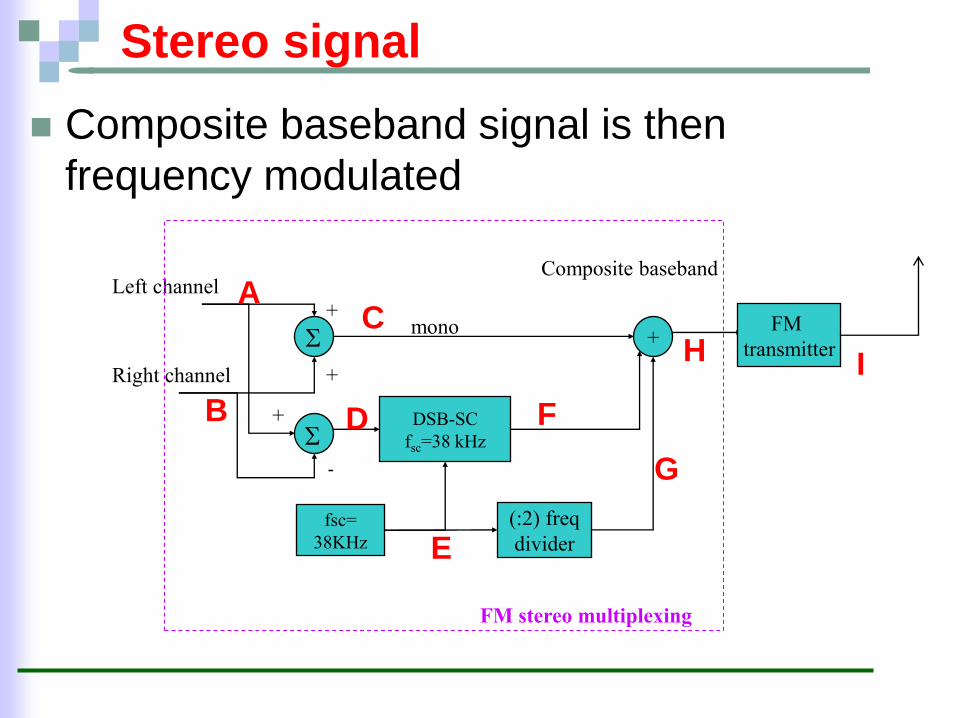
Stereo signal
Composite baseband signal is then
frequency modulated
Left channel
Right channel
+
+
+
mono
DSB-SC
fsc=38 kHz
+
fsc=
38KHz
(:2) freq
divider
Composite baseband
FM
transmitter
-
A
B
C
D
E
F
G
H I
FM stereo multiplexing

Stereo spectrum
Baseband spectrum holds all the information.
It consists of composite baseband, pilot tone
and DSB-SC spectrum
38 KHz 19 KHz
15 KHz
Left+right DSB-SC

Stereo receiver
First, FM is stripped, i.e. demodulated
Second, composite baseband is lowpass
filtered to recover the left+right and in parallel
amplitude demodulated to recover the left-
right signal
38 KHz 19 KHz
15 KHz
Left+right DSB-SC

Stereo receiver diagram
FM
receiver
lowpass
filter(15K)
bandpass
at 38KHz
X lowpass
VCO Divide 2
X lowpass
+
+ -
+
+ +
Left+right left
right
PLL
coherent detector A
B
C
D
E F
38 KHz 19 KHz 15 KHz
SA(f)
FM stereo demultiplexing
G
H
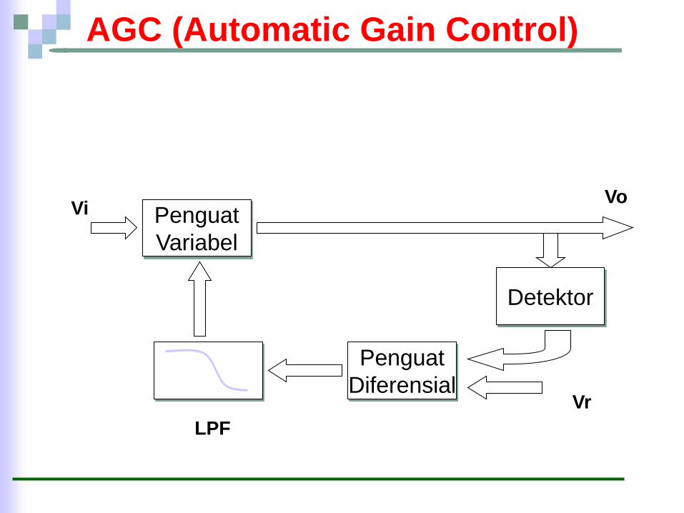
AGC (Automatic Gain Control)
Penguat
Variabel
Detektor
Penguat
Diferensial
LPF
Vi Vo
Vr

AGC (Automatic Gain Control)
V2 V1 Vi
Vo

MATERI UTS: MODUL 1 – 6
SIFAT UJIAN : TUTUP BUKU
LAMA UJIAN : 2 JAM (4 SOAL)
TIPE SOAL : ESSAY


![Penguat Differential [2]](https://static.documents.pub/doc/80x56/577c83381a28abe054b41ba1/penguat-differential-2.jpg)

![Penguat Daya [2]](https://static.documents.pub/doc/80x56/577c83381a28abe054b41bc5/penguat-daya-2.jpg)
![Penguat Daya [3]](https://static.documents.pub/doc/80x56/577c83381a28abe054b41bfa/penguat-daya-3.jpg)