, '. Nudear Engineering and Design 140 (1993) 3-18 North·Holland Recent advances in concrete containment vessels in Japan 3 T. Kuroda', T, Ebine b, S. Sato • and M. Kato d .• Shimizu CotporQlion, 2·3, ShibaUTrl l-ehome, Muuzw-ku, Tokyo 10S.()7, Japan . • Agency of Nalund _ tINl £nerBy, Murishy of InJemtllWnilI Trade tINl Industry, 3-1, Kasumigasdd I-ehome, Oriyoda-lcu, Tokyo 100. Japan , Tokyo Ekctric p__ Company, 1-3, UcIrisaiwtU-dro l-ehome, Chiyoda-ku, Tokyo 100, Japan • Japan Alri l'<Twrr Company, 6-1, 0tDnadri l-ehome, Chiyoda-ku, Tokyo 100. Japan Rec:cmcl 18 September 1992 An oudine of the development of concrete containment vessels in Japan for use in nuclear power plants is described, whete \be emphasis is laid on the reinforced concrete containment vessel (RCCV) teeentfy developed Cor \be advanced boiling watcr reactor (ABWR). Also explained arc the salient features of concrete containment vessel design which are unique in Japan; aamely stringent seismic requirements. thorough verification and DOYel containment concept Fmally the design principles applied to RO:V are presented along with tbe design standard. L Introduction A majority of nuclear power plants in Japan presently in operation. under construction and in preparation belong to light water reactors (LWR). Namely 52 units out of 53 units are LWR's, which consist of 23 units of pressurized water reactors (PWR) and 29 units of boiling water reactors (BWR) As can be seen from table I, the prestressed con· crete containment vessel (PCCV) was first adopted in PWR's for the 1160 MWe Tsuruga Power Station Unit. 2 which started operation .in 1987, and since then all the 1100 MWe class PWR's built in Japan have em· ployed PCCV. In BWR's the RCCV was fust intro- duced into the 1356 MWe ABWR Kashiwazaki-Kariwa Power Station Unit 6 and 7 (I(6/7) which are Clq)CCled to begin their operation in 1996 and 1997 respectively. The use of RCCV for ABWR is one of the unique features of ABWR by which a significant improvettlCnt is expected to be made to the operability, safety and economy of BWR. The devdopment worIt for ABWR was completed in 1985 and it is anticipated that the future BWR type jlower reactors will be dominated by ABWR. . Now it must be mentioned that there are some unique features to be noted in the concrete contain- ment vesseJ development in Japan. The salient features among them are as follows: - Stringenlldsmic - 11wrough veri[laJlion by a series of extensive exPeri- mental studies - Novel COIttaiJunolt conapt building/containment (RCCV) integrated structure for ABWR. In this paper the presentation is centered on these three important features. Finally a brief explanation is given of the design principles and standard relevant to ooncrete containment vessel. 2. Seismic requiremeDts 2.1. Basic requiremmts 2.1.1. Basic princip/u An overview of the seismic design procedure for nuclear power plants in Japan is shown in fig. 1. In general, seismic design is conducted in accordance with the following sequence in such a way as to conform to the regulatory guides and [2-6). (1) Preparatioll of basic Ipformation, including identi- fication of the earthlluakes to be considered in design, . (2) Estimation of earthquake ground motions and in- put motions induced by the earthquakes thus iden- tified, (3) Estimation of seismic forces acting on the plant by seismic response analysis and static seismic reo quirement, 0029-5493/93/$06.00 C 1993 - Elsevier Science Publishers B.V. AlI rights reserved
Transcript
, '.
Nudear Engineering and Design 140 (1993) 3-18North·Holland
Recent advances in concrete containment vessels in Japan
3
T. Kuroda', T, Ebine b, S. Sato • and M. Kato d
.• Shimizu CotporQlion, 2·3, ShibaUTrl l-ehome, Muuzw-ku, Tokyo 10S.()7, Japan .• Agency of Nalund _ tINl £nerBy, Murishy of InJemtllWnilI Trade tINl Industry, 3-1, Kasumigasdd I-ehome,Oriyoda-lcu, Tokyo 100. Japan, Tokyo Ekctric p__ Company, 1-3, UcIrisaiwtU-dro l-ehome, Chiyoda-ku, Tokyo 100, Japan• Japan Alri l'<Twrr Company, 6-1, 0tDnadri l-ehome, Chiyoda-ku, Tokyo 100. Japan
Rec:cmcl 18 September 1992
An oudine of the development of concrete containment vessels in Japan for use in nuclear power plants is described,whete \be emphasis is laid on the reinforced concrete containment vessel (RCCV) teeentfy developed Cor \be advancedboiling watcr reactor (ABWR). Also explained arc the salient features of concrete containment vessel design which areunique in Japan; aamely stringent seismic requirements. thorough verification and DOYel containment concept Fmally thedesign principles applied to RO:V are presented along with tbe design standard.
L Introduction
A majority of nuclear power plants in Japanpresently in operation. under construction and inpreparation belong to light water reactors (LWR).Namely 52 units out of 53 units are LWR's, whichconsist of 23 units of pressurized water reactors (PWR)and 29 units of boiling water reactors (BWR) (1~
As can be seen from table I, the prestressed con·crete containment vessel (PCCV) was first adopted inPWR's for the 1160 MWe Tsuruga Power Station Unit.2 which started operation .in 1987, and since then allthe 1100 MWe class PWR's built in Japan have em·ployed PCCV. In BWR's the RCCV was fust introduced into the 1356 MWe ABWR Kashiwazaki-KariwaPower Station Unit 6 and 7 (I(6/7) which are Clq)CCledto begin their operation in 1996 and 1997 respectively.The use of RCCV for ABWR is one of the uniquefeatures of ABWR by which a significant improvettlCntis expected to be made to the operability, safety andeconomy of BWR. The devdopment worIt for ABWRwas completed in 1985 and it is anticipated that thefuture BWR type jlower reactors will be dominated byABWR. .
Now it must be mentioned that there are someunique features to be noted in the concrete containment vesseJ development in Japan. The salient featuresamong them are as follows:- Stringenlldsmic~nts
- 11wrough veri[laJlion by a series of extensive exPerimental studies
- Novel COIttaiJunolt conapt building/containment(RCCV) integrated structure for ABWR.
In this paper the presentation is centered on thesethree important features. Finally a brief explanation isgiven of the design principles and standard relevant toooncrete containment vessel.
2. Seismic requiremeDts
2.1. Basic requiremmts
2.1.1. Basic princip/uAn overview of the seismic design procedure for
nuclear power plants in Japan is shown in fig. 1. Ingeneral, seismic design is conducted in accordance withthe following sequence in such a way as to conform tothe regulatory guides and~ [2-6).(1) Preparatioll of basic Ipformation, including identi
fication of the earthlluakes to be considered indesign, .
(2) Estimation of earthquake ground motions and input motions induced by the earthquakes thus identified,
(3) Estimation of seismic forces acting on the plant byseismic response analysis and static seismic reoquirement,
0029-5493/93/$06.00 C 1993 - Elsevier Science Publishers B.V. AlI rights reserved
4 T. Kuroda <lol.l Con=I< rontainment vasds in Japan
Table IConactc containment ~Is in Japan
Type Reactor Power Output Startlns oCoC Type ColIpany Plant Techlcal Standard Operation
CCV (Ill/e) (Scheduled)
JapanAtomic Tauruga 1160 Technical Standard oC Prestreued Feb. ,1987Power Unit 2 Concrete. Containment Vessels Cor~ny Nuclear Power Plant
laMal Obi 1180 (Dec. ,1991)PCCV PIlR Electric Unit 3
Power Obi (peraission oC partIcular) (Feb. ,1993)ColIpany Unit _ 1180Des\in bl HITI Ordinance
Genu! No.2. Article 3(Har.,199_)Kyusyu 1180
Electric UnIt 3Power Genal
ColIpany Unit _ 1180 (Jul. ,1997)Technical Standard Cor Concrete
~hlwazakl1356
Conta1nllent VesselTokyo -Karlwa Cor Iluclear Power Plant (Jul.,1996)UnIt 6
F,.. 1. Flow of seismic desian pmcedwa for DUdear power p....es In J.......
T
I
s
(4) Estimation of stresses, strains, deformations, etc.resulting from seismic f<?:rce5,
(5) Finally. review of structural integrity and safetyfunction of the plant in light of acceptance criteria.
In practice, all the plant items are first classified intothree tategories, A. Band C according to their importance. There is one more class, that is As, on which themore stringent requirements arc imposed in additionto the requirements as A. Containment vessels belongto this As class. In principle, using the design basisearthquake ground motions, a dynamic analysis is performed for class A items to obtain the seismic forcesother than the static analysis. A time dependent seismic response analysis technique is usually employedfor the analysis of buildings and structures, but thistechnique is used for some of the-major equipment andpiping as well. A static analysis is required for allclasses, and the intention is to dctcnnine the minimumseismic forces (S<H:a1led "seismic floor") to be takeninto account in the design, on the basis of the requirements set forth in the Building Standard Law, BuildingStandard Law Enforcement Order, Notifications ofMinistry of Construction and relevant regulations(bereafter referred to as "Building Standard Law").
It can be said that there are three main features inthe seismic requirements and practices prevailing inJapan. They are S, and S, design basis earthquakeground motions, seismic classification and static analy.sis requirement to arrive at design seismic forces.
21.2 Design basis tiJrthquau growuJ. motionsPresented herein is an outline of how the design
basis earthquake ground motion is defined in Japan.Figure 2 shows the locations of nuclear power plants inJapan and the two levels of the maximum accelerationsof design basis earthquake ground motions S, and S2employed for these plants. Although the maximunt'acceleration is not a good measure of the damagepotential of earthquake ground motions, they are shownhere as an indicator of the seismic intensity at eachsite. It is seen that they range from 180 to 4SO gal forS, and 270 to 630 gal for S,. The Japanese Guide (3)(hereafter referred to as "Guide") requires that thedesign basis earthquake ground motions be classifiedinto S, and S, as described below. Ground motion S,is induced by the S, design earthquake that is themaximum design earthquake thought probable to occur, and ground motion S, is induced by the S, designearthquake that is the extreme design earthquakethought possible to occur.
According to the Guide, the design basis earthquake ground motions are defined as the ground motions at the free surface of the base stratum of a site.The Guide also says that Uthe free surface of the basestratum" is a nearly nat surface of the base stratumextending over a considerable area. and above whichneither surface layers nor structures are assumed to bepresent. The base stratum is firm bedrock which wasformed in ,general in the Tertiary or earlier era and
[
I:[
l'"
, ,
, .
SHIMOKlTA
ONAGAWA
FUKUSHIMA
SENOAl
SHIMANE
.HAMAOKA
TSURUGA
SHIKAKASHIWAZAIO
MIHAMA
OH'OHAGAWA
SHIMOICITA
TOMARISENDAIGENKAI !=='it=::J
FUKUSHIMATAKAHAMA F=='!=iw I----,
IKATA Ps;'SZ
TOKAI ~~~:.,-:~:!:-~~100 ." • .. 100 110 (pI)
"'11- 2. Design eutbquake acceleration Ie>ds in Japan (p~ unit of acceleration, an/.').
KASHlW~l
TOMARl
I.
6 7: KurodJJ d. at / Concme contaiNrtenJ uessds in Japan
• ..... a.pUtude..-- .-teetaala ~I.tla......,-• auratioft T~..-- and £notelope
"""...... function .....Low Actt..F.-It ...-- -"(Sz Dalp ..........._' IIcItl.. Sz
har F••WEarUtquah
"'6.5
ObHnatlonor
£ar~keCltuIcr".tlonot GroundT..-ra
Fig. 3. Flow chart for determining design basis earthquakeground motions 51 and 81 ,
which is not significantly weathered nor fissured. InJapan bedroclc is, in general. llQnsidered to exhibit ashear wave velocity greater than 700 m/s.
Figure 3 shows how the design basis earthquakeground motions S. and S2 be established in Japan foruse in nuclear power plant design. First of all, it isrequired to determine the S. and S2 design earthquakes which give the design motions S. and S2' An S.earthquake is determined· primarily OIl the basis of therecords of historic earthquakes and high1y active faults.
Table 2Seismic dassifocation
Statistical expectancy based on the records of historicearthquakes is also taken into account in estimatingthe intensity of S, earthquake motions. An S2 earthquake is detennined on the basis of seismo-tectonicstructure at a site region and the active fault withrelatively low activity. In addition an earthquake ofmagnitude 6.5 occurring directly underneath the sitemust be assumed to occur as the S2 design earthquake.
The earthquake ground motions are characterizedby the maximum amplitude, frequency characteristics.duration time and time-dependent variation of amplitude envelope curve. Based on the S. and S2 designearthquakes, these parameters can be determined. Using these information, thus the design basis earthquakeground motions S. and S2 are established in the formof design spectra and synthesized ground motions.
21.3. Seismk cJassijiaztion Dnd design seismk forceTable 2 gives the definition and examples of seismic
classification. It is a mandatory requirement in Japanthat all the plant items be classified into the threecategories A. Band C in accordance with their importance in terms of the public safety. Oassified as class Aare the items containing or related to highly radioactive material. and whose loss of function might lead tothe release of radioactive material to the atmosphere,and such items required to protect the public fromnuclear hazards in the event of a nuclear accident.Essential items among class A items such as. reactorcontainment, shutdown devices, and primary coolantsystem are classified as As. Such items related toradioactive material but baving relatively minor effectiveness except those classified as class A are classifiedas class B. Oass C items are those not classified as
SeI_Ic Definition ExupleClassification
IClus AsFacilities extre-ely essential to plant Reactor contaln-eQt, Reactoraatety _ Class A it_ coolant pressure boundaries,
Core shutdown JrVstela etc.raeilitiea t-portant to plant ~rety or Reactor auxll1ary building,
Clasa A related to radioactlve _terW Emergency core cooling .ystell,Emersency oct''''''IU aystem, etc.
Sue as Clasa A but _ M1pture .ight lead Turbine Bldg. (BVRl,Class B to lea serlous consequences Rad-wute treatment BYsteal, etc.
FacUlties not claultled as A or B, ancl the Turbine Bldg•. (Pl/Rl.Class C _ degree ot aatet)" as ord1aary industrial Turbine Generator. etc.
DynaJalc forces derived fr'om design bub earthquake ground !lOtions 52 and S,VoiCor-. Vertical forces based on 1/2 1laX1aua acceleration amplitude (gal) of$2 and S, IlOtionS divided by acceleration of cravlty (980)Shearing force coefficient to be deterilined troca the standard shearingeoetrlc1ent of 0.2 and other considerations such u response characteristicsor building ~ so11
.II) Cv Vertical setSll:lte coefficient or 0.3 and 1a unifo~ value irrespective ofheight
5) For equlpctent and piping, the above static value IlUSt be multiplied by a factor of 1.2
[
rr
Table 4Load combinations and allowable limits - Basic principles
, .
"i, 1
••
, .
I!' I
r: 1
Appllcabl. to bulldlnc and struotur. only.Required In .... of .........t .Ibratlon oilly.5to!')' shear coefficient'.rtlcal oe1olllc coefflolentRequired berlzontal ult_te strength
8 T. KurodtJ et aL / Concrete t:onIaintnent vessels in Japan
class A and B. which are only required to maintain thesame degree of safety as ordinary industrial facilities.
Table 3 shows the· relation between design seismicforces and seismic classification. It is required according to the Guide that all the class A items includingclass· As items be designed to the design basis earthquake ground motions S., while only the class As itemsare required to be designed to tb:e design basis earthquake ground motion S2' The basic concept behind theuse of two levels of design earthquake S. and S2 is thata nuclear power plant must remain intact and cancontinue its operation during and after the maximumdesign earthquake S. which is thought probable tooccur, in addition to maintaining its safety functionduring and after the extreme design earthquake S2which is thought possible to occur.
It will be noticed that the static forces are larger inthe order of importance, namely in the horizontaldirection 3, 1.5 and 1.0 for A, B and C respectively. Itwill also be seen that the seismic forces in the verticaldirection arc only required for class A, and no dynamicanalysis is presently required in the vertical direction.It should also be pointed out that the static forces arc20% larger for equipment and pipings than for buildings and structures. This is because of the consideration for the minimum response amplification relativeto buildings.
21.4. Acceptance criteria for seismic qwz/i[u:ationThe acceptance aiteria for seismic qualification of
nuclear power plants in Japan are outlined with emphasis placed on load combinations and allowable limits. Table 4 presents the basic principle of load combinations and allowable limits prevailing in Japan. Basi·cally it is required for class A items to take intoaccount an occurrence of the maximum design earthquakes S. under DOrmal or upset condition. For classAs items such as containment vessels, It is furtherrequired that a simultaneous occurrence of the designaccident and maximtim design earthquake S. be considered a1~ough it is a very remote probability, inaddition to a combination of normal or upset conditionplus an occurrence of the extreme design earthquakeS2' .
In principle the class A items arc required to re-o main elastic under S. loading condition, and the detailsarc stipulated in the Japan Electric Association's Technical Guide (6) to meet this intent in accordance withthe stress category in the case of equipment and pipingfor example, such as primary stress, secondary stressand local stress, wbile the newly established MITI
Notification [7] is applied to conaete containmentvessels.· ;
In the case of class A and B buildings and structures, it is required to follow the allowable fimits forshort term loading stipulated in the Building StandardLaw, if they need to remain elastic. Although it isallowed for the most essential As items to exceedclastic limits, they are required to possess a sufficientmargin for deformation capability and a certain appropriate margin against ultimate state or slrcngth for thesake of retention of safety function of a plant.
22 &quirmtents for concrete conlainmcnt lICSSCls
Seismic forces ading on conaete containment vessels are estimated in accordance with the above-mentioned seismic design sequence, and in the case ofPCCV for a typical recent PWR plant, its response atthe top of the dome is obtained at approximately 2700gal and over 3000 gal under the S, and S, earthquakeintensity level of 365 gal and 532 gal respectively (gal;unit of acceleration. an/sl ). The maximum story shearcoefficient at the bottom of containment vessel underthe above condition is estimated at 1.31 and 1.57 (8).
In the case of RCCY's, since the cenler of gravity ofdeeply embedded containment/building structure isfairly lowered as compared to other LWR's, the designis dictated by static forces rather than dynamic forces.
It can />c noted from the above examples that thestringent seismic requirements were one of the incentive to employ PCCV's in the case of PWR's, and thatthe use of RCCV!building combined structure has anadvantage in teons of seismic resistance capability.Upon the introduction of PCCV's and development ofRCCV's, for the purpose of proving the seismic qualifi'cation and appropriateness of design approaches anextensive research and development works were carried out as mentioned hereafter in section 3.
~ Verification by research and development
3.1 hertrased Concrete ConItUnmenJ V....l (PCCV)
Upon construction of the Tsuruga Power StationUnit 2 which is a 1160 MWe class PWR, the JapanAtomic Power Company (JAPCl decided to employPCCV based on the comparison of four different typeof containment vesse~ ordinary stccl.spherical vessel,bigh tensile steel cylindrical vessel with icc-<:ondcnser,RCCV and PCCV. The reasoo for selecting PCCV wasthat PCCV bas been widely used in the USA and
Table 6Eoperimeatal studies for the _lop...... of PCCV
I .,..1
Item OutUno
In-plane • In-plane shear testa or RC plate, RC &: PC cylindrical .cSel and PCj
Shear cyUndrlcal lIOdel with _. thwI evaluatlDc dtlolato In-planeshear .trength.
Out-ot-plane • PuSh-ott tests of RC blocks, thus Investtp.tlnc shear transferShear aechanl.-. and evaluaUne 8hear strencth. .
KITI• Intemal pressure tots of at cylindrical wall, thus evaluat1ng
dtlolato out-ot-pl8ne shear .trength ot bue "t cyUndrlcal wall'erlflcatton bued on resistance of clrcwlterentlal rebar relnforceMnt. ,Tests
• Therwal stress testa or ftC beau, thus studJ.nc reduction ratio ofTberll&1Streaa the..-l ........ ot Ie beea.
• Internal preasure + therMl load testa of bue or cylindricalwall, thus conrlrainc that ultt.ate shear streneth or the base i.not ettected by thef'll&1 .........
Lorge Friction • StreulDc tee.. ot 1000 ton clua tendone by tull .cale partWCepeclt~ Lon, etc. .cdel, thus lnvestisatine trlotion loss coetficients andTeadon ests -.tructeblllt,..IfatorW CODcreto • CoDcrete properties teat on actual CODCr'ete tor fauruca 2, thusT.... Properties lilftstlptlng eulteble _...... Ill........ ......p propertl.. end
tbelW&1 properties ot concrete.
----~ --------
10 T. Kuroda d at / Conuele containment vessds in Japan
Europe and it has some advantages over the others intenns of seismic resistance capability (9).
Although over 100 PCCV's have been completed orare under construction in the world. a number ofverification studies have been conducted in Japan inaddition to the establishment of standard becausePCCV is the first 1arge structure of its kind in Japan.These studies include optimization of strueture (shapeof dome, buttress, tendon capacity; bonding, etc.), amceptual design and numerous verification tests. Iodicated in table 5 is the sehedule of PCCV developmentactivities.
The Ministry of international Trade and Iodustry(Mm) organized a committee in 1975 for the establishment ot technical standard of conerete containmentvessel for nuclear power plants, which looked into therelevant standards in Japan as well as the ASME ende
Table 7Major parameters of PCCV
and others. When the first draft of the standard wasprepared in 1977, the following two comments weremade by the committee.(l) Lack of studies both in Japan and overseas regard
ing the in-plane and out-of-plane shear stress whenthe containment vesseI is subjected to a combinedstress of membrane foree resulting from internalpressure and shear force.
(2) Necessity for studying the method of evaluatingstiffness in estintating themtaf stress.
On the basis of this review, the decision was made toperform verification tests as part of the MIT1 LWRstandardization aetMties to confirm the requirementsfor evaluation of out-of-pIane and in-plane shear stressand thermaf stress [lO~ 10 addition electric utilitieswith assistance from industries carried out various verification tests using models subieeted to loads such as
Plant Name Tsuruca Unit 2 I Chi Unit 3&" I Genlcal Unit 3&"
Shape or ccy Cyllndrleal Shell with Spherical Dome
Tendon CorIpoaltloa 16301_ or _155 ........ ot Iz.s-I \63 .1ra ot '-
Teadoa CapacItJ . 1,000 toas olue
T. Kwoda n 111. / Concrete conlairunent uessds in Japan
q
i ~
r11 I:
r
[
intemal pressure, temperature and horizontal force,and experiment.1 studies on large capacity tendons(see table 6) [11,121.
In light of the outcome of the above-mentionedstudies, "Mm Technical Standard (Tentative)" was~
established in 1979 which was then revised in 1981 [131.Construction permit has been issued to the TsurogaUnit 2, Obi Unit 3&4 and Oenkai Unit 3 after submitting the PCCV Technical Guideline wbich was prepared for each plant-by-plant basis in accordance withthe Technical Standard.
Major parameters of the PCCV's are given in table7. It is obvious from this table that they are identical. interms of dimension and design requirements except forminor differences in construction material and pre·stressing system.
In-8ervice Inspection (lSI) has been conducted forthe TsuNga Unit 2 one and three ye.r after the s(artof operation, and its structural.integrity has been COnfinned by checking prestressing force of tendon, anehorage, grease, concrete, etc.
A feasibility study has been undertaken .in 1978 bythe world's five BWR manuf.ctures (GE, Toshiba,Hitachi, ASEATOM, ANSALDO) aiming .t develop- ('"jog an .dvan<led version of the BWR (ABWR) on thfO,basis of technologies of conventional BWRs. Since thattime numerous studies have been conducted, Le: 3rdPhase LWR Improvement and Standardization by theMm, Conceptual Desi&n by the Tokyo Electric PowerCompany (TEPCO) .nd Industries, SlIUctural Evaluation and Verification Tests for Establishment of Standard by the Electric Utilities/Industries 10int Study. ('Consequently ABWR has been successfully developed ..nd adopted for TEPCO's Kashiwazaki-Kariwa Unit 6.nd 7, which are deemed to be equivalent to theMm's 3rd phase standard LWR. Usted below are the [ :main features of ABWR [14]. "(1) Adoption of .n internal pump for reactor coolant
recirculation, thereby eliminating the outer pump. I"(2) Adoption of • reinforced concrete containment
Table 8Developmen' of ABWR
I;f' tr !
jI , !J
I ,
, .
.
-1971 78119 80 \81 1821831811 185186181 f 88 89190191 f92193T9-195196191 19819912000IlIpt"OVe.ent and StandaNllzatlon Progr...
Govcr.-ent Phase I...... ~ I( KITI ) I ....... HITI Notice 990.10.22 IIotlce Enactelent« !
vessel which is structurally combined with the reactor building.
(3) Adoption of impfOYed control rod drive mechanism.
(4) Adoption of improved reactor core.(5) Scaling up of plant output by the use of high..,f-
ficiency turbine, etc.As part of the end-product of _this cIeoclopment, acylindrical RCCV was developed as listed in the abooe(2) which is integrated with the building to make asingle combined structure- having the following advantages:(1) Freedom in shape, which leads _to a reasonable
shape meeting the equipment and piping layout.. requirements.
(2) Ideal hybrid _structure with steel liner functioningas leak·proof membrane and conacle as prcssu.resustaining structure, shielding and seismic wall ofreactor building.
(3) Smaller size of RCCV and lower gravity center,thus enhancing seismic resistance capability.
(4) Shortening of construction period.Table 8 shows the schedule of RCCV development
activities [14~ Since RCCV is the first structure of itskind newly adopted in Japan, a trial design was performed in accordance with the above-mentioned Tech-
Dical Standard in addition to a series of verificationtests as the joint effort of BWR utilities aiming at thestructural evaluation and establishment of the reinforced concrete containment vessel. From the structural viewpoint, there were three outstanding aspectsto be investigated as follows:- The RCCV structure is under a complex combined
stress condition resulting from a tensile membranestress by internal pressure and stresses by otherloads.
- The RCCV top slab is stiffened by pool girders.- The RCCV is combined with the building through
building slabs.Accordingly the following experimental studies were
conducted(I) Basic design data has been accumulated on the
shear strength under an axial tensile state by experimental means using beam and disc models. Theresults thus obtained were rellected upon the MITINotice 452 along with the knowledge derived fromthe previous shear tests.
(2) A partial model of top slab was tested to failure byinternal pressure, thereby confirming the amplemargin for ultimate strength (maximum pressure atfailure was four times the design pressure.)
(3) An entire scale model of the RCCV/building slab
@ Trunerse Shear @Tonlonal LoMlac(D Expert_at of <D Experillut of Total
Expert.ats .a Expert.ats •• Cr·Be.. EteMa' ~-:er vltb top Sla• MacIel i. lArle Seale•,nn~
.. - m• I I .peci••apecl••• .pecl••• ~ speel.a lalerAllllellbra.e laler•• l 1:1 t:1 ,resnre
rzJ VJ Bendt ftC .a·plaftc .resslll'e The,...,1 load....ar 1112 shear 1110 Ther.. l load '" Koril.oata' force
~ l l A. YerlflcaUo••f the@ Tr.....ene She.r t t lCCY's lateett tr
.ExPert.ats ••~Experl..t •• lolat
I. eoaUflNllOa .f thDllk MlMel <» SMar !xterl_t UIU..le Slreacth, - .f Llaer Aadaar of Diephr... ''Ioor C. ""UealtHilr of
~lpecl... lhe Dellp 5.....,..
I.
~,
~r..e specl__ specl.u D. '.U41t, If....., • lite Des 1Ii:_ lie IbMr.-,~;.r;t:. Shear· Tusl..
III 1/3 ....,D@ Experl.ats of Ie iW~tl-.l of lber <i> Stn.et.,.••.lxperl·
combined SlrUeture was tested by loading internalpressure. temperature and horizontal seismic force,and compared with the analysis results to confirmthe validity of desigo method, and then the modelwas tested to failure by horizontal foree, therebyassuring the ample margin for ultimate strength.
Figure 4 is a Dow chart showing the entire experi-mental research work, which consists of basic study,>erification studies by partial structural element models and an entire scaled model.
Tobie 9MlQor panmeters of RCCV
The structural integrity under desigo loading conditions as well as the ultimate strength and its lIlarginwere confirmed. The outcome of these studies wasalready presented in the 10th SMiRT Conference [l5).
FIgUre 5 and table 9 show an outline of the struCture and major design parameters of RCCV's for K6f7.K6f7 is presently in the preparatory stage for construction, and an effort is under way to study construction method and sequence, In-service Inspection ofRCCV structure, etc.
(:Et-l' 1L
••'laDt .... IashUrazaJd-lariwa Ua.it 10.' • T
.Sbape or CCY Hybrlcl Cylinder and top Slab with Steel I.1ner and leactor ..Wine
1b1ckDeu ot CJl1Dder 2.0 •
~~1Ie1lbt or C)'lll1der (Interoal) 29.5.lmaer DiaMter 29.0.1b1ofc:nea ot Top Slab 2.2. - 2.-' •fotal 1Ie1lbt ......t 36 ° (fo o.,wou _)Start or Operatloo (SCboduled) Unit , June,1996 , ODit T .Ju.1J,1991
Oulp Dulp ........... 3.16 ..tl....Cr1- Tat IPruaure 3.56 ..t/~....1&
anticipation for the continued adoption of concretecontainment vessels in the future, Mm established acommittee and issued the 'Technical Standard forConcrete Containment Vessels for Nuclear PowerPlants' as MlTI Notice 452 (hereafter referred to as"Standard") in 1990 [7).
The basic principles of the Standard are as follows:(I) Reference was made mainly to the relevant stan
dards in Japan as well as the intent of existingequivalent foreign standards such as the ASMESec. III Div. 2. Furthermore experiences gainedfrom the design, construction and operation ofprevious conacte containment vessels were wellreflected upon the Standard.
(2) Load combinations are classified into four LoadCategories I-IV, which in principle correspond tothose of the ASME Sec. 111 Div.2
(3) Requirements for seismic design are stipUlated.(4) Consideration is given that regulations for steel
portion are consistent with those of the Mm Notice SOl <Technical Standard for Structural Designof Mechanical Components of Nuclear Power Facilities).
The Standard applies to concrete portion, steel linerplate, liner anchor, penetration sleeve, penetration anchor, attachment to liner plale. and so 00. Thoseportions consisting of steel only are subject to regulations stipulated in the Mm Notice SOl. The Standardis composed of four chapters which are outlined intable 10.
4.2 Load cat<gOMs, loads and load combinations
Load combinations are classified into four cale·gories "Load Categories I-IV" depending upon the
-"",,_............
1Sdffnets of MI stiobY~. ---ToW ef Nodn : ItSJ
To~ of ae-nts: JU'
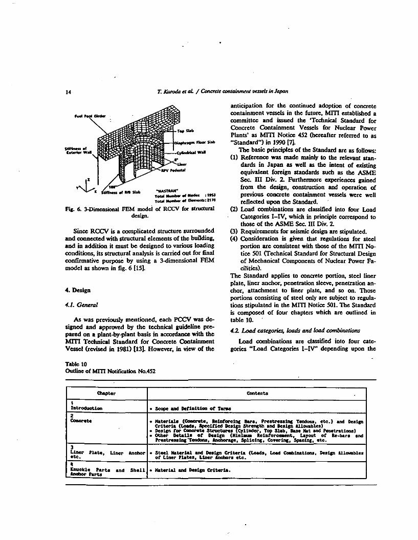
F"JC. 6. 3-Dimcnsional FEM modcl of Rex:v for strue:tura1design.
As was previously mentioned, each PCCV was designed and approved by the technical guideline prepared on a plant-by-plant basis in ac:oordance with theMlTI Technical Standard for Concrete ContainmentVessel (revised in 1981) (13). However, in view of the
.........
Since RCCV is a complicated structure surroundedand connected with structural elements of the buiJding,and in addition it must be designed to various loadingconditions, its structural analysis is carried out for finalconfirmative purposC by using a 3-<1imensional FEMmodel as shown in fig. 6 [15).
_oflderiot Wall
Table 10Oudine of MI1l NotUlC8tion No.452
a.p... eon.....
Ilatroduotion • SCope aDd Detla1tioa of 1'...2.......... • Kater1a1a (Concrete. 1e1Dtoreinc Bara:, Prestre..lDc Teadou. etc.) and Deelp
Criteria (L0ad8, IpecUled Des~ Strength and De81p Allowablu)• Des1p for Concrete Stnlcturu CyUDder, Top Slab, Base Mat and Penetrations)• other Detail_ ot De81p (Hlat-u. Relntorce-ent, Layout ot Be-bar. and
•lauclde Parta a.d Shell • Kater1a1 ud Dut.ca Criteria.- ......
'1;.~
nIS I:
frequency and simultaneous occurrence of loading, andcadi structural element is designed in accordance tothe requirements to each Load Category.
Load Category I is defined as normal operatingcondition, while Load Category II as safety relief valveoperating condition, test condition and snow load condition, and basically under these I and II conditionsthe plant is required to maintain its function for thelong-term operation.
Load Category III is defined as abnormal conditionother than I and II such as accidental and seismicloading conditions. Under these shortterm loading conditions, the plant is basically required to remain belowelastic limits. Load Category IV is defined as extremecondition postulated in safety design where the plant isrequired to maintain its safety function.
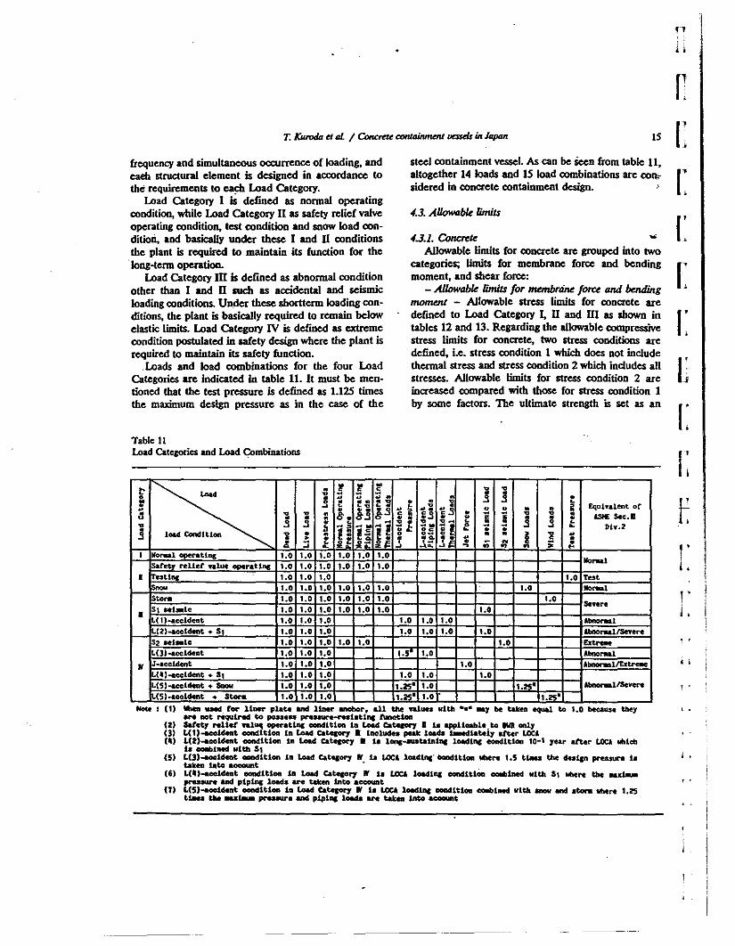
.Loads and load combinations for the four LoadCategories are indicated in table 11. It must be mentioned that the test pressure is defined as 1.125 timesthe maximum design pressure as in the case of the
Table 11Load Categories and Load <;::ombinations
stcel containment vessel. As can be Seen from table 11,altogether 14 loads and IS load combinations are COllisidered in conaete containment design.
4.3. A/JowQbk /imils
4.J.1. Concrete ...Allowable linrlts for concrete are grouped into two
categories; linrits for membrane force and bendingmoment, and shear force:
- AI10wabk /imils for rnembrtiM force turd boIdingmoment - Allowable stress linrits for concrete aredefined to Load Category I, II and III as shown intables 12 and 13. Regarding the allowable compressivestress limits for concrete, two stress conditions aredefined, i.e. stress condition 1 which does not includethermal stress and stress condition 2 which includes allstresses. Allowable linrits fur stress conditio. 2 areincreased compared with those for stress condition 1by some factors. The ultimate strength is set as an
~ • • @. ~. ! .- ~ • ~ :s ~• !: • ,~ ,. •& • :.E &0: u= • ;; N 0 {l~ ~ ...~ ~f. ~ n n '"I No~l operatinc I.. t •• I •• ••• I.• I .•safety relief ftlue operatlne I •• t •• t.O I .• I •• I .•
.......• est11li1r t •• I .• t •• I •• Tes'
t •• I .• '.. I .• I •• ••• ••• .......to... t •• 1.0 ••• 1.0 ••• ••• •••
S, ..I_Ie ••• I .• I •• t •• ••• ••• severe
• •••L( 1)..eeldent I •• ••• I .• I .• '.0 I.. ..........L(2)-accldeat • 51 ••• I .• I •• I •• I •• I .• ••• Abnorul/Se"er-eS2 ftl.le ••• I .• 1.0 ••• ••• ••• E......L(])-accldent I •• ••• I •• 1.51 t.o Abnorw.l
• J·.ccldent I .• ••• I •• I .• AbnorwallExtr-eL(lI)-accldent • SI I •• ••• '.. I •• I •• I ••L(S)..ccldeat • Saow ••• I •• I •• 1.,..1 I •• 1.25' Abfto~llSevere
US)-aceldent • Ito... ••• I •• '.. 1• • I •• 1.251
!'L
, ,
... : (1) 'laesa used. Cor liner plate and liner anchor, all the ftlues vith -.- .,. be taken equal to 1.0 beuw:e they t •
.... DOt required to posse_ pr.......- ...st.t1nC tuncttoa(2) latet, reUef ft1~ operat1nc: condition In Load Catec0r7 • u applicable to M onlJ(3) L(U-ace1deat ooncIltlon in Load Cate&OI"J • InclUdes peat loads IMedlateiy liter LOCi(tI;) L(2)-acc1dent condU:loa In Load catecor, • Is lonc-autalnlne: loadlne condition 10-1 )'eI.r' after LOCA tlhleh
Is COIIblned .,Ith 51(5) L(3)-accldeat CDDdltlon In Load CatecOl"J rt u LOCA loadl.."OXtdIt1oa title... 1.5 tliles the daten pres.sure fa
taten loto account .(6) L(")..eo1deat eondltion 1a Load Catecor'1 " u LOCA 10&cl1ne eorwsltlOa oel.lldDed ulth 51 MIeN the MX'"
preuure and plP1Dc load.a are t&ten Into accouattT) L(S)ooaocl.dent ooadltlon fa Load Catecot'1 IV .. LOCA loMtne oondittoa eoIblned vlth InCN and .tonI tlhtre 1.2'5
t•• the ..... ,......,.. and piplllc 10aQ are takea into account
16 T. IWrodtz d aL / Conc:me conlainmenJ Vt:SSm in Japan
Table 13Allowable stress (2. Shear stress of concrete)
and II is defined as 1/2 of the ultimate shear strengthused for Load Category IV, while the limit for LoadCategory III is defined as 3/4 of the same. ,
The following is the equation used for estimatingthe ultimate strength.
(i) In-p1Jzne skar stfM8lhOn the basis of horizontal loading test results using
reinfon:ed and prestressed concrete cylindrical models,the in-plane shear strength is determined from thestrength obtained from the assumption of only steelbeing effective as restraining fon:e and the upper limitof concrete strength as follows;
'u- H(p,.lr+ 00.. -u~) + (p"lr+u.. -u..)}.
and 'u ;f, 35{F.,
where'. : ultimate tangential shear stress,p,•• p" : reinfon:ement ratios in meridional (~) and
circumferential (6) directions respectively.qo., uOI: Membrane stresses in ." and 8 directions
respectively which are induced by an external force except for a prestressed fon:e (thesevalues become positive for tensile stress and°for compressive stress).
a:., upI: effective prestressed stresses in q, and 8P directions, respectively,
I r : specified yield strength of bars,F, : specified design strength of ooncrete.
(a) Out.:o,-p1JzM shur S1rtnglh .
For the out-of-plane shear strength. a new equationis used which is proposed based on the test results suchas push-off tests, shear tests for oolumns and beamsand reinforced concrete containment vessel. whereoonsideration is given to the coefficient of reductiondue to shear span ratio.
,,,-4i{O.I(p,lr-uo) +05P.I,+0.7SIF.}. and
'R:F. 35{F..
.......IIote • Fe 1a Spec
. Allowable to.prea:slYe StressLoad Catq0t"J'
Stress Condition 1 Streu: Condition 2
• • I Fe I 3 ,Fe I 20
• 2Fc I 3 3Fc I 4
!tied deal •• ..·.r ......... (....'...)
Load Catesol"J Allowable Shear Stress
Fe Fe.&1 IAsMrot- .... 5· --
30 '00
• the above X 1.5. ••• •• th or concrete(qtle-")
allowable limit for the combination of membrane forceand bending moment for Load Category IV, and thestrain limits of CODaete and rebar in estimating theab<we ultimate strength are determined to be the values indicated in table 14. Additionally it is stipulatedthat the allowable limit for the compressive stress ofconcrete under Load Category IV be below 2/3 of thespecified design strength.
- AIIowabk Iimil for skar folU for wU portion With regard to the allowable limits for in-plane shearfon:e and out-of-plane shear force, and the limit forout-of plane shear fon:e acting on the bottom of thecylinder which is induced by axi~etricloading, theultimate shear strength derived from the test results isused as the baSis for an allowable limit for LoadCategory IV. The allowable limit for Load Cateao'Y I
Table 14Slnin limits fo< _ and ldDfon:iDa bar ia Load CateIOIl'IV
Hater1a1 'alue or Llalt StralllCocc.... cc.preulft : 0.003
Relatorclnc bar teQUe and CIOIIP.....lft : 0.'!05
where'R : ultimate out-of-plane shear stress.PI : ratio of reinfon:ement to totaI cross section,000 : membrane stress caused by external fon:es (this
value becomes positive for tensile stress).P. : ratio of out-of-plane shear reinforcement,4> : Coefficient of reduction by M/Qd.4>-
1/';M/(Qd) , 058:r. 4> :r,I, where •M : maximum bending moment of cross section,Q : maximum shear force of cross section,d : effective cross section.
Table 15Straln aUowables for liner plate
T. KurodtI <t 41. / C>ru:r<te containm<nl v=ds in lapan
Table 17Displacement allowables for linear anchor
pL
r17 rr
Table 16A11owab1es for liner~r
.....To ~lcal Loacb.........
'&1 Leuer 0.' ,aaO.61 .F) and 'a-o.33 Fu.." teaser or '.-0.9 fJ and F••O.5 Fu
De.ian Allowable..... Claasltication or -..... Kellbrane •CateCOI"J Strains bend1nc
(iii) Out-ol-p/tln< sMar stmtgthat bottom 01shellThe following equation based on the yielding of
re--bars in circumferential direction is used for estimating the ultimate out-<lf-plane shear strength at thebottom portion of the shell connected with the foundation when it is subjected to axi-symmetric loading.
'"H-I0p"I,/(13.2.{fJ -fJ),
\:1
r~Jri
i, j
Il
1•
I ,
,
I .,
r
[
I',Note: 11,1 i. dbplacelllent or liner anchor at rracture.Which .,. be deteraiDed on the bub or •theoretical Or experlMntal reaul t..
Acknowledgement
Owing tq the above-mentioned extensive verification sludies and actual design and construction experiences, CCII's are proved to function satisfactorily as asound ..rety barrier in earthquake-prone countries tikeJapan.
The Kashlwazaki-Kariwa Power Station Unit 6 and7, the first ABWR's employing RCCV, are currentlyunder Iiqonsing review and is e>pCCled to start itsconstruction in 1991.
In light of further advancement of technology, aneffort is presently being made by on-going studies 10develop a more advanced method for use in concretecontainment vessels in.the near future, for example, toupgrade the quality of concrete during constructionand to develop the optimum non-destructlve method toinspect the struetucaI integrity of CCII's during operation by automatic devices•
s. Conclusions
to function as struetucaI elemen!, the provisions forclass 2 vessel in the MlTI NOlice 501 are to be followed.
Uno anchor - Table 16 shows the allowable loadlimits of the Hner anchor when subjected to mechanicalloads. Indicated in table 17 are the allowable deformation limits for liner anchor which are induced In lineranchor by forced strain of liner plale. When the lineranchor thought to act as support structure, it is stipulated that the provisions in the MITI Notice SOl are tobe followed.
LoadDl-"laCleMnt. Allowable.
Category
I • I 1a;o.25 11,1.. " 1&",0.5 '1,1
: ultimate out-<lf-plane shear stress,: reinforcement ratio in B direction.: specified yield strength of reinforcing bar,
r : radius to center of wall,t : thickness of containment.
4.3.2 Uno p/4te and~ anchorUno p/tlte - Allow8ble limits for the strain induced
in the liner plate by constraint or forced deformationare indicated in table 15. The provisions for class 2support structure in the MID Notice SOl are to befollowed when liner plate is subjected to external load(mechanical load) and is thought to function as supportstructure transmitting this load to concrete, Qd whenliner opiate is not suppOrted by concrete fm case theliner is subjected to negative pressure) and is thought
where
'"HP.,I,fJ- r / t
Mote: "U 'leU .treneth ot liner U\<IbOC'.Fu. 1a ultt.te atrenCtb ot liner anchor.a.:: ru .., be deterw1ned on the buu or
tloaJ. or eapert.eatal ruulta.
The authors expteSS their sincere appreciation tothe people participated in a serieS of studies for CCV'sfor their cooperatinn and furnishing the data.
1,
18
References
(I] Japan Atomic Euergy Commission, Atomic Euergy WhitePaper (1990), in Japanese.
(2) M. Watabe, M. Kato and T. Kuroda, Procedures, Analy·sis and Research on Earthquake Resistant Desians forNuclear Power Plants (Oct. 1982).
(3) Japan Atomic Energy Safety Commission, ReplatolYGuide for Aseismic Design of Nuclear -. ReactorFacilities (July 1981), in Japan....
(4) lapan Atomic Energy Safety (;Nnmissim, Committee onExaminatioo of Reactor-Safety. Guidelines 00 Lic:cnsiagExamination for Geology and Ground Condition or Nuclear Power Plants (Aug. 1978), in lapan....
lS) Ministry of International Trade and Industry, TechnicalStandard for Structural Design of Mechanical CompoDents of Nuclear Power Facrnties. Mm NotificationNo.501 (1980), in lapane...
(6) lapan Electric Association, Technical Guide for SeismicDesign or Nuclear Power Plants (JEAG4600 (Sept. 1984),in lapanese.
(7) Ministry of International Trade and Industry, TechnicalStandard for Concrete Containment Vessels for Nuclear
Power Plants, Mm NotifICation No.4S2 (Oct. 1990), inJapanese.
(8) M. Watabe, M. Kato and T. Kuroda, Seismic Design andQualification of Nuclear Power Plants in Japan,1AEAjPRC Training Course, Safety Analysis Review ofNuclear Power Plants (April 1985).
(10) Result Report of Mm LWR Improvement and Standardization Program (March 1979), in lapan....
(11) Japan Picstulled Coacrete Eoginecring Association,Journal of Ptesb ssed Concrete, JAPAN, Vol.23. No.1(Jan. 1981), in Iapanese.
[12] Japan Prcsb Sled Concrete Engineering Association,loumal of Prestressed Coocrete,IAPAN, Vol.28, SpecialNumber (Dec. 1986), in lapanese.
(13) Mm, Technical Standard of Concrete Containments forNuclear Power Plants (Nov. 1981), in lapanese.
(14) Tokyo Electric Power Company, Advanced Boiling Water Reactor CBroebure).
[IS) JL Saito, et at., &perimenlal Study on RCCV or ABWRPlant (Part 1), 10th SMiRT, Aug. 1989.
Reccivcd 18 September 1992
Containments design for the Advanced and Simplified BoilingWater Reactor standard plants -P.F. Gou ", H.E. Townsend ", P.S. Sawhney b, K. Mandagi band N.B. Duchon b
• G<n<raI_ Company, Nudau En<rrY MIe 154, 175 Outn<rA_ San lost, ~ 95125, U&f• 1kcJlld _ Cotporarion, San Frandsi:o, CA, U&f
Nuclear Engineering and Design 140 (1993) 19-26North-Holland
19
rrI:I:
The Advanced Boiling Water Reactor (ABWR) design is based on construction and operating experience of nuclearpower plants in Japan. United States, and Europe. To optimize the plant arrangement of the Advanced Boiling WaterReactor (ABWR) and to verify the structural fe..ibility to <any design loods a study was condueled. To arrive at anoptimized plant arrangement witb a minimum size reactor building (RB). • circular cylindrical reinforced concretecontainment vessel (RCCV) with a flat top slab and a monolithically connected diaphragm slab bas been selected.
The Simplified Boiling Water Reactor (SBWR) is being developed as a standardized 600 MWe Advanced 11ght WaterReactor. The design concept of the SaWR is based on simplicity and passive features to enbance safety and reliability,improve performance and increase economic viability. Due to tbe use of passive containment cooling. SBWR bas featuresthat are different from. those of Qistiog designs.
The objectives of the study for the ABWR containment and RD are to perform a structural analysis o( the containmentand RD and to evaluate the structure (or con(ormance to the U.s. NRC requirements. The main objective o( the studies (orthe SBWR is to demonstrate the structural design feasibility o( the containment for the pressure and the temperatureresponse associated witb the passive systems adopted for the SBWR.
I. Introduction
The Advanced Boiling Water Reactor (ABWR) design is based on construction and operating experienceoC nuclear power plants in Japan, Uni1ed States andEurope. General Electric and Bechtel performed studies in 1984 to optimize the plant arrangement oC theABWR and to YCriCy the structural Ceasibilily to carrydcsip loads [1,2). A comparisonoC major plan1 specifications Cor theAB~with those oC the current seneration oC Japanese BWR can be Cound in ref. (3).
The Simplified Boiling Water Reactor (SBWR) isbased on simplic!ly and passive Ceatures to enhanceuCely and reliabilily, improve performance and increase economic viabilily. Usc of the pressure suppression system, graYity-drivcn cooling oystem (GDCS) andpassive containment cooling system (PCCS) aUows dieelimination oC safely grade emergency diesel senerators, core cooling pumps and heat removal pumps thussimplifying plant design and rccIucing plant costs. ReCerence (4) gives a comparison oC features for the SBWR
with those for the current conventional BWR and theABWR.
The objectives of the study for the ABWR containme"t and RB arc to perform a structural analysis oCthe containment and RB and to evaluate the structureCor conCormance to the u.s. NRC requirements.
11Ic main objective oC the studies Cor the SBWR isto demonstrate the structura1 dcsip Ceasibilily oC thecontainment Cor the pressure and the lemperalureresponse associated witIJ the passive systems adoptedCor the SBWR and to demonstrate that a 3O-monthconstruction schedule can be achieved. More detailedinformation can be found in ref. [S].
:z. Description of the containments and the reactorbuildings
To arrive at an optimized plant arrangement with aminimum size reactor building, a circular cylindricalreinforced concrete containment wsscl (RCCV) with a
! '
L
, -
, ,
, -
, -
0029-5493/93/$06.00 C 1993 - Elsevier Science Publishers B.Y. All rights reserved
20 P.F. Gou <I al. / ONrJainmmts duignforrlu: A&S BWRs
flat top slab and a monolithically connected diaphragmslab has been selected. The flat top slab is integratedwith the fuel pool girder.; which are framed into theRB struetural walls and floor.;.
The ABWR containment has 29.0 m inside diameter (10): and is integrated with the reactor building.The containment and the reactor building are supported by a common foundation mat. The bottom of
1'~.d1C!O I' WQfS'U\
IIr-.
o -.. m IuctM PuCIT...
rn ~''''"F... 1. ABWR CXlIItaiameat and reaCtor bui1din&-
I c::J c::J c::J c::J c::J c::J c::J c::J CD m m m
r----------~----------------• ,
E=] =tlJL, ,, ,, ,, ,, ,, ,• •:
c:~=r-I--rotDCJo L-I IC Ii h iLJc:::Jm c::J oocz
f1,II
r21 r:
I:~ [
I:I:[
..I:.5
;g•.<>u
~ I:t..,c•C• ! .Ec r. r..c8
~,.;.. j •....
Ii;
, .
22 P.F. Gou <t aL I ContaiIrnKnlS tksignfortMA&S BWIU
the foundation mat is embedded in the ground 25.9 m(85 ftl below grade. The major oontainment internalstructures oonsis! of the reactor pedesta~ !be reactorshield wall, and the, diaphragm floor. The reactorpedestal is a eomposite steel and eonerete structure,the pedestal eonsists of two Concentric steel shells tiedtogether by vertical steel diaphragms. A reinfon:edeonerete circular diaphragm floor slab serves as a barrier between the drywell and the we!welL The diaphragm floor is supported by the oontainment wall andthe reactor pedestal The top of the RPV is supportedby the reactor shield wall by means of RPV stabilizertruss.
The RB of the ABWR is a 59 m (193.5 ftl by 56 m(183.75 ft) reinforced oonerete structure. The buildinghas six reinforced eonerete floors which are monolithically eonnected to the oontainmenl. The operatingfloor at elevation U,.7 m (87.6 ft) is not directIy eonnected to the oontainmenl, but is oonnected to the fuelpool girders which are supported by the eontainmentand the RB. The interior walls and the floor beams arenot connected to the containment structure. The ar·rangement of the RB and the oontainment is shown infig. I.
The SBWR plant due to the use of passive eontainment cooling, has features that are different fromthose of other existing designs. The Isolation Condensers (I.e.'s) and the passive oontainment coolingsystem (PCCS) that removes decay heat by naturaleonvection and evaporation are in pools which arelocated on top of the drywell. To maintain long termcooling and water ooverage of the reactor eore, thesuppression pool (SP) is elevated to such a level thatwater can flow by gravity from the SP to !be reactorafter LOCA.
The SBWR oontainment has 31.5 m 10 and ispartially integrated with the RB. It eonsists of thereactor pressure "'5Se1 (RPV) pedes~ SP floor slab,the cylindrical oontainment wall' and !be drywell topslab. The drywell top slab supports the IC pools andservice pool The IC pool girders on the dryweII topslab provide strength to resist containment pressureloads. The top slab has a large opening (D - 9.4 m) in!be middle for the dryweU head and four apenings(d - 3.2 m) for the lC's and PCCS. The >ent wall
: structure and the diaphragm floor slab arc: steel structures filled with eoncrete. The RPV pedestal supJlO!'\Sthe reactor veSsel, reactor shield wal~ >ent wall strpp.lure and the suppression pool.
The RB structures for the SBWR eonsists of theRCCV and three rectangular "boxes" supported on aoommon basemat of 66.3 m x 66.3 m with intereon-
neeted slabs at various elevations as shown in fig. 2.The structures are primarily of reinfon:ed eoncreteeonstruction. The bottom of the foundation mat isembedded in the ground 23.0 m (76 ft) below grade. Inthe present design for SBWR, the RPV pedestal formspart of the eontainment pressure boundary. It wasdecided to adopt a reinfon:ed eoncrete pedestal withliner plate on the inner face acting as a leak tightboundary. This was judged to be more desirable than asteel-<:oncrete eomposite pedestal, based on eonsideration of applicable design codes, severe accident eonditions and construction requirements including modularization.
3. Design criteria
The containment. structures are designed in accordance with the ASME boiler and Pressure VesselCode, Section III Div. 2 [6].
The containment temperature and pressure conditions for normal, testing and WCA eonditions eonsidered in the study are shown in table 1. Pool hydrodynamic loads and the eorresponding eontainment pressure are also considered. Temperatures greater thanlSO"F are postulated to last a long period of time aftera LOCA or postulated severe accident conditions inthe SBWR. Degradation of material properties is expected and, therefore, temperature dependent material properties are eonsidered in the analysis and design.
4. Seismic analysis
. The seismic analyses for the feasibility study of theSBWR standard plant were performed with lumpedmass model as shown in fill. 3. A range of soils waseonsidered in terms of shear wave velocity (u). Evalu-
• For SBWR tbete iclRperaluRs ..., exist lor up '" 30 daysafter LOCA and have beeu considered iu the cIesiIn-
I
P.F. Gou.ul. / C<NrIainnr<Iltstfajgnfor ,heA&S BWRs
ated soils include soft soil willi u - 300 m/s, 500 m/s,.intermediate soil with u - 1000 m/_ and hard soil withu- 1500 m/_ and 3000 m/s. Two sets of input motionwere used. One based on a peak horizontal groundaa:cleration of 0.3 Z (SSE) with a response spectrum
per US NRC Reg. Guide 1.60. The other based ~'Japanese Mm Standardization program for LWR i"l .Japan. In addition, a parametric seismic analysis was'performed for various idealized site oonditions as pre- .scuted in ref. (9). I:
..
J •
..
L LLJI 'l ~
[
~I l'
i:]T I ~i
GR1l!miEvEl ~ ;*~..;. I u.
-------j ~.I ; ~
! ~I,I
LEC£>Cl
II HASS NODE
o BEAM ELEMEN' NC.
- BE41'1 El(tlENT
I--SOIL sn"NESS
-.Y#'-~y STA8LL::~A
-=-R(GIO COtlPL!-«:
--.-. UIAL ElEf"IEHT
IICevSAFETYEllVElDP£
INTEJlt<EO."8
OUTSIOE R/e& ROOF
REF'UE:UNC BELLOWS
r---~.'------.,
::=u,.lllL....w~:...J..~,;...L~~
n,6
".5S
'3.6
'.1
loIS
.,
zo
a
-'a
'.e
24 P.F. Goo".L I Cont.inm<nts <!<sign for theA&S BWRs
5. Analytical models and structural analysis
The containment and the RB are analyzed as oncintegrated structure utilizing the finite clement computer program STARDYNE. The structures are idealized as a three-dimensional assemblage of linear elasticbeam and plate elements.
The models include the geometry and the materialproperties of~r structural components consisting ofthe containment wall, reactor pedestal, reactor shieldwall, reactor ocsse!, foundation mal, diaphragm floor,containment top slab, fuel pool girders, and the RBfloors, walls, columns, and roof. The underlying foundation soil was represented by spring elements. Theside soil was not included in the model. The foundation soil was adjusted to include embedment effects.The lateral soil pressure was considered during theevaluation of the RB outer walls. The finite elementrepresentation of the structure for the ABWR is shownin fig. 4 and for the SBWR in fig. S. For the ABWR,because of symmetry, 180" model was used where asfor the SBWR, 360" F.E. model was used.
The structural analysis consisted of four steps:- the formulation and decomposition of the stiffness
matrix,- the static analysis for the load eases,- the combination of loads, and- the stress analysis of rebar and concrete.
u
Fig. 4. Finite element model for ABWR containment andreactor building.
PO,.. S. FInite element model for SBWR CXlIIlainmeat and IeaClor bulldi...
P.F. Goo <t at / Con'ainm<nu d<sign for 'he A&S BWRs 2S
nL
r:
The rebar and concrete stress analysis was performedusing Concrete Element Cracking Analysis Program(CECAP). The element represents a section of a concrete shell or plate, layers of reinforcing steel, and aliner plate. External forces, as input, consist of moments in two directions, axial forces in two perpendicular directions, in plane and transverse shear forces.The program outputs stresses and strains along theelement in the concrete, reinforcement; and the linerplate. CECAP assumes linear strain relationships forsteel and concrete in compression. Concrete is assumed to have no tensile strength. The solution is aniterative process, whereby tensile stresses found initially in concrete are relieved due to concrete craclcingand redistnbuted in the element, The equilibrium ofnon-thermal loads is preserved. For thermal effects,the elem~nt is assumed free to expand inplane, but isfixed against rotation_ The capacity for expansion andcracking generally results in a reduction in thermalforces and moments from the initial condition.
6. Slroctural assessment and conclusions
Although the design criteria and seismic analysisdiscussed in sections 3 and 4 respectively, are for theSBWR. similar design criteria and seismic analysisbased on a range of soil conditions were used for theABWR study. The results of the ABWR study showthat with the present configuration and wilh RCCVwall thickness of 2 m, the containment and RB can bedesigned as standardized plant or generic site to meetthe ASME Section Ill, Division 2, and the NRC requirements.
The reactor building and the containment for boththe ABWR and the SBWR. were analyzed by fmileelement methods nsing plate and shell elements. Theco~te cracIcing effects were evaluated by suocessiveIterations. The evaluation results demonStrate that theRCCV wall of 2.0 meter thickness can be adequatelyreinforced to resist the loads discussed. The RCCV, asdesigned for LOCA conditions, can withstand a s=eaccident pressure of at least two times the designpressure value together with associated temperatures.Similar conclusions were reached In ref. [7) for a s\ightly\arger SBWR containment but with somewhat differentconfiguration. .
The details of analysis and results for the SBWRtop slab are presented in ref. [8]. The results show thatthe design is feasible with the specified number oflarge openings In the slab.
Similar to the ABWR. design, the RCCV of theSBWR plant Is integrated with the RB by RB floor
slabs at various elevations and by the pool girders onthe top. For the evaluation, a finite element model wasprepared, and analysis was performed using the STARDYNE computer code. In a series of iterations thestiffness of highly stressed elements was reduoed toallow for redistribution of forces due to concrete crack-~
ing. The study results showed that for the presentconfiguration with integrated RCCV, RB, and poolgirders, the structural design is feasible_ Even thoughlarge shear stresses are induoed in the pool girders dueto the thermal srowth of the RCCV due to LOCAthermal loads, based on the initial elastic analysis, thethermal stresses are significantly reduoed after accounting for relaxation due to craclcing of concrete.
The reactor building for the SBWR. has floor slabsat various heights. Integration of the RCCV with theRB is advantageous from seismic design considerations. However, when the design for LOCA pressureand temperature and construction are considered, inte·gration of all floor slabs with the RCCV is not desirable. To optimize the structural responses it was decided that the two structures be integrated only at:• Suppression pool bottom floor slab level• Suppression pool top slab level• RCCV top slab level• Operating floor.
II was decided not to integrate the remaining floorsof the RB with the RCCV. A separation gap has beenprovided between these slabs and the RCCV wall, withappropriate detail for the required leak tightnessagainst flooding, fire, etc. This will prevent containment pressure and thermal loads from being transmitted to these floor slabs, thus making their design moreeconomical Also, in absence of floor integration withthe RCCV, the construction of RCCV can be expedited.
The vent wall structure is made up of two coocentric steel cylinders with vertical stiffeners in-between.There are 8 vcnt pipes that are equally spaced betweenstiffeners. The remaining spaces are filled with concrete. This type of construction lends itself well tomodularization and off-site prefabrication. The designin feasible with 30 mm thick steel plates.
Diaphragm floor slab is a steel structure consistingof continuous top and bottom plates with circumferential stiffeners and radial vertical web plates In between.This lends itself to modular construction and providesfor easy anchorage of GDeS pool steel framing andthe pipe support structure in the drywe\\.
The evaluation results of SBWR show that thestructural design is feasible for the pressure and temperature responses associated with the passive systems
adopted for the SBWR in conjunction with seismicloads derived from various soil conditions to ",presentgeneric site.
Study was also perfonned about constructability ofthe RB. The results showed that by using large scaleprefabrication and modularization and based on use of1000 ton crane with rolling 4 X 10's, work week (70working hours per weelc), a 3O-month constructionschedule from start of structural conaete to the fuelload is achievable for "n-th of a kind" planL FJ&U'" 2shows ~me of the large structural modules consideredin this study.
References
(I) P.F. Gou and p.s. Sawbney, Design of reiaforced concretecontainment >asci (RCCV) for the aclvaoocd BWR nuclear power plant, TraDsactions of the 9th IntcmationalConference on Structural MechaniCs in Reactor Technology,1987.
(2) K. Mandagi, p.s. Sawbncy, N.B. Duchon, G.1.. Bame< andP.F. Gou, Containment de<ign for the aclvaoocd boi1ing
water reador (ABWR) standard plant, Transactions of the10th International Conference on Structural Mechanics inReaCtor Technology, 1989.
(3] OK Wilkins, T. SoIto, S. Sa&mo and H. Hashimoto,Nuclear Engineering International (June 1986).
(4) RJ. McCandless, J.R. Rcddinl, Simplicity: the key toimproYed safety, pcrfonnaacc and ec:onomics, Nuclear En·&ineering International (Nov, 1989).
(5) P.F. Goo, H.E. Townsend, p.s. Sawbncy, N.B. Duchon,M. Olivieri. T. Gyotoku, S. M'araio and M. Tsutagawa,Containment design of the Simplified IloiIing Water Reae.lor (SBWR) plant, Transactions of the 11th SMIRT 1991.
(6) ASME, Boiler and Presswe Vcsscl Code, Section DI, Div.2, Subseclion cc (1989).
(7) p.s. Sawbncy, G.1.. Ilamcs, N.B. Duchon and P.F. Gou,Integrated reactor buildm,/amtaiamcnt design of a Simplified Boiling Water Reador (SBWR) plant, 10th SMIRT.1989, pp. 61-66.
(8) M. Olivieri. G. Viti, M. F_M.F. Moholker, P.F. Gou,SBWR·RCCV top slab design by analysis, 11th SMIRT,1991, HI2-3.
(9) M. Oliver, E. Travenone and G. Vit~ SBWR'Duciearisland parametric seismic analysis. Transactions of the11th International Conference on Structural Mechanics inReactor Technology, 1991.
Nudear Engineering and Design 140 (1993) 27-31Nnrth-Holland
Containment concepts for High Temperature Reactors
27r
J. A1tesINltUuu fO<' SofdY _ """ &4d0<' T<ehn%gy, _ c.nur TuIidl (KFA), P.O. Box 19I3, 5170liilich I, G<muu1y
Received 27 November 1992
Different containment concepts have been proposed for Hi&b Temperature Reactors. In the paper the confinement. thepstight ptOSSUrized containment and Ibe ""nted confinement .... discussed. For a smaU HIll such as the Modul it seems tobe possible to prOYide • 'Vented COIlfinemeo.t instead of a pstight coataiament._Thc German Reactor Safety Commission has&iveU • posith<e statement. Due to the specific safety characteristics of the KfR the safety concepts can differ in part quitecoosidcrably from current LWR standard solutions.
[i
I'(u
0029-S493,193/S06.00 C 1993 - ElsevIer Science Publisilcrs B.V. AIl rights reselVcd
I. Introduction
During the past three differenl containmenl concepts have been proposed for High Temperature Reactors. The prototype reactor nITR-300 which was under construction from 19n \0 1985 and is now out ofoperation has a confinement. For the HTR 1160 project of the mid-l970s a gaslight pressurized containment was considered necessaiy, while for the recentplant concepts of medium and small power, the HTRSOO and the Modul, vented CO!Ifmements are proposed.In the paper these different CO!Ifmementland contain-ment types are discussed ,', '
2. Conlalnmettt reqairements
The requirements for containments are specified inthe 'Safety Criteria for Energy-Producing Plants withGas-O>oled High-Temperature Reactors' [1). According \0 these criteria, the plant must have a containment\0 fuIfi1 its safety-ldated functions in normal operationand during accidents. .
In coojunction with the coolant confinement andother retention barriera for radioac:tive substances, thecontainment must ensure that the requirements stipulated by the AtomIc Energy Ad and the RadiationProlcction Ordinance are met for the as..'med dis-
charge or release of radioactive substances into theenvironment in normal operation and during accidents.
The confinement of the reactor coolant must beaccommodated within the containmenL Any other plantparts containing radioactive substances must also beaccommodated within the containment unlesS the requirements of the Radiation P/Otection Ordinance aremet by other suitable measures.
The containment including aU penetrations, airlocksand awaliary equipment, as functionally required furaccidcqt control, must be designed in such a way that itcan withstand static, dynamic and thermal loads innonnal operation and during accidents to the extentrequired in order \0 fulfil its safety-related function.The containment must maintain its iniegrity in the caseof external impacts.
The requirement that the containment must maintain its integrity in the case of external impacts means:- The leak tightness and load-bcaring capacity of thecontainmemm~be_ured~p~fmco~~
with the provisions m the Radiation Protection OrcIinancc for accidents can only be furnished underthe tightness condition. •
- Only the 1oacI-bcaring capacity m the containmentneed be ensured ~ proof of compliance with theprovisions of the Radiation Prolcclion Ordinancecan also be furnished without the tightness criterion.
. Containments of reinforced and prestressed concretem~ comply with DIN 2S 459 (9).
I
E(rJ,.1 '
L
• •
, .
·,
·.
28
3. Containment concepts
3.1. Con[m.-nt of th~ THTR-300
J. Alit,. / Containment canapU for IfTRs
Activity release in R. rooms is suppressed by structural design measures. In addition, a partition is provided in two afterheat removal systems.
The confinement system of the THTR-300 consistsof the following parts [2,3) (Fig. I):- the burst-proof reactor pressure vessel of pre
stressed concrete in which the primary cireuit isIoeated,
- the so-ealled vent wall around the pressure vessel,- the so-ealled safety shell composed of the walls
between rooms R t , respectively R z and R],- the auxiliary systems for retention and ftItering of
possible leakages.The R. rooms contain systems which are in contactwith the primary circuit during operation or accidents.They are of pressure-resistant design. The maximumaecidental gas leakage, which is limited to 5.5 kg/o, eanbe discharged dirCctIy into the stack through a separatedepressurization system. The R 2 rooms also containprimary gas conducting systems. Possible gas leakages(max. :> 1.83 kg/s) are controlled and discharged intothe stack by the normal exhaust air system. The R.rooms do not contain any systems which are in directcontact with the primary system. All systems connectedwith systems in R I and R 2 rooms ean be isolated.
au.....11.5.
.,.""h-.d'O*C)
ns.
ll.l.
11.2.
LO.
·4.111
F"II- 1. Confinement of the nrt'R-300.
3.2 &actor protection buiIdin: as a gastight pressuriudcontainnwll of1M HTR-ll60
The basic design of the planned large HTR-ll60plant includes a containment similar to those usuallyprovided in LWRs, i.e. a gaslight pressurized containment [41 The reactor protection building differs fromthe reactor hall of the 300 MWe THTR nuclear powerstation with respect to the building requirements andtype of construction. It serves both as the primarysystem containment and the surrounding building. Thispurpose defines the functions and the safety-relatedsignificance of the reactor protection building, i.e. towithstand all internal loads arising from the plant andall external loads including, in particular, also aircraftcrash, chemical explosions and earthquake.
The THTR containment function was basically assigned to the reactor pressure vessel of prestressedconcrete without depressurization system and with agaslight liner. For this reasont great significance wasattached to the proof of liner integrity in the designphilosophy for the TIITR prestressed concrete reactorpressure vessel.
The HfR reactor protection building differs fromprevious light·water reactor containments (with theexception of Grundremmingen 2 featuring a prestressed concrete containment> in that there is noannular gap between the containment and the surrounding reactor building. The concrete structure ofthe building must therefore accommodate both theexternal loads and the internal pressure in the event ofa loss--of-coolant accident, whereas the liner must ensure the tightness of the building. The tightness of thereactor protection building was specified with a leakrate ofO.3%/d under aecident conditions at~"C and4.05 bar.
1be reactor protection building essentially consistsof a cylindrical shell which is placed on a cireuIarfoundation slab and covered by a hemi-ellipsoidal dome(fig. 2). The inner surface of the concrete structure issealed from the atmosphere in the reactor protectionbuilding by a &ncr - a steel lining fitted directly ·to theconcrete and anchored therein. The penetrationsthrough the concrete structure are designed as gaslightpipe penetrations.
The cylindrical part of the reactor protection building is preslrmed in the cireumferential and verticaldirections. 1be horizontal tendons are anchored on 3
,
rrrIj
!in
I:E1:I;1~ I, rL
1' IL II .,j •
,
••
29
01J 1I! ffiJlEBmm
prevented even after external impacts, in particularaircraft crash. . '4
There are two possibilities of complying with thisrequirement which is decisive for the concept:- furnishing proof that the reactor proctection build
ing is still sufficiently tight after an external impact..especially after an aircraft crash, !lr
- furnishing proof that no Ioss-of-coolant accident oc·curs due to external impacts if the leak-tightnesscannot maintained after external events.
o
L AJt« / Containmmt conc<pts for HTRs
EB
butresscs (120" pitch) on the cylinder outer wall. Thevertical tendons arc anchored in an annular support atthe upper end of the cylinder. and, at the bottom, in theouter prestressed gallery of the foundation slab. Thetendons of the dome arc anchored in the ring girder atthe upper end of the cylinder. Due to the doublefunction of the reactor building as both the safetycontainment and the surrounding building, it has tomeet the requirement according to 111 criteria 2.6 and8.1, that any release of radioactive substances must be
FIIo 2. Ractor proleclion buDdin. of the Hm.-1160.
30 L Aha / Con/4innrmt concepts for HTRs
The primary rooms are connected by openings inorder to achieve pressure equalization as rapidly aspossible. After having reached the equalization pressure of 1 bar, the pnossun: n:lief naps close automatically and directional ventilation is established again inthe building. The n:lief ducts an: additionally providedwith a nomotely closing flap cach.
Ventilation of the rooms in the n:actor building isdesigned for the selective release of radioactive fissionproducts. Primary circuit leakages up to a leak size of 2m2 can be accommodated and filtenod by-the ventila.tion system.
The German Reactor Safety Commission has evaluated the proposal and docs not have any safety-relatedobjections to the concept of activity confinement 'Theconcept is suited to ensun: that the regulations of theRadiation Protection Ordinance for Donna! operationand 4csign basis accidents are complied with.'
In the United States also the concept of a ModularHigh-Temperature Gas-Cooled Reactor (MHTGR) ispursued. The reactor building of this design docs notprovide a leaktight, pressurized containment, but controlled venting instead. In NUREG-1338 (8) lhe NRCexplains:
The staff recognizes that a design without a conventional containment building presents a significant departure from past practice on LWRs and that undercertain situations LWR containment buildings havebeen effective components of the defense-in-depth approach. Therefore, designs that deviate from suchpractice need to be n:viewed to ensure that an equivalent level of safety as that of curn:nt-generation LWRsis maintained and that uncertainties in design andperformance are properly accounted for. The staffbelieves thaI such designs are possible, although theultimate acceptance of such designs will require extensive noview, testing, and demonstration. Accordingly,the staff proposes criteria to be met in ord~r to certifya reactor design without a containment building withthe understanding that in noviewing a design againstthese criteria, a larse burden will nosl with the appli'eant to demonstrate compliance, particularly in view ofthe uncertainties associated with a new design.
The following an: proposed criteria that advancedreactor designers must meet for NRC certification of adesign without a containment building:(l) The design should contain multiple barriers to ra·
diation release that limit radiation n:lease at leastequivalent to that of currentlleneration LWRs.
(2) The fission-product.....tention capability of the design must be demonstrated via a testing programutilizing a full-sizc prototype plant consisting of at
The HfR·Modulconcept docs not provide for a gastight containment It is based on the fact that therdiable confinement of radioactive fISSion products inthe fuel element is ensured to cuch an extent that
, cnviromncntal exposure remains below the pcnnissable6mIts in aU acddents [5,61-,
The reactor protce:tioll building without liner bas adouble function in that It protects the reactor apinstextcmal impacts and ensures controlled activity n:leaseof primary c:lrcuit leakages into the environment (fig.3). This means that thC dcsisn docs not aim at completely confining the activity over long periods of ,""c,as ccncrally practiced, but ~or lcakaccs (rangingfrom o.s to US q ofhelium/s) an: dischaqcd throuahthe depressurization system and minor Ieakall""throuah the exhaust air syStem with filters into thestadc and the CIIYironment
J. Alta I Containm<rrt_, lor HTRs 31 J:least one reactor module and the associated systems, structur~ and oomponents necessary todemonstrate safety.
(3) Different emphasis and types of QA, suIVeillance,in-erviee inspection, and inserviee testing over andabove that traditionally employed on LWRs shouldbe provided.
(4) Protection of safety-related systems, structures, andcomponents from sabotage and external events.should be provided that is at least equivalent tothat for current-generation LWRs.
(S) The design should have specific measures to ensurethat core heat up accidents, accidents with signifi.cant positive reactivity feedback, or other accidentswith the potential of a large radiation release, suchas graphite fires, have lower frequencies than 10-7
per plant-year.(6) An assessment of the potential improvement in
safety if a containment building were added wouldhave to be made. Judgment would then be used todetermine the need for a containment buildingbased on the cost and change in risk.
These aiteria are intended to maintain at least thesame level of protection of the public and environment, bY specifying equivalent dose guidelines andprotection, as is provided bY current-generation LWRs.
4. Conduslon
For High Temperature Reactors of small powersuch as the Modul it seems to be possible to providevented confinements instead of the gaslight pressur-
ized containments of the current generation LWRs.ThO' German Reactor Safety Commission has given apositive statement. The final determination of the acceptability bY the NRC is contingent on evaluation ofadditional information. Due to the specific safety characteristics of the High Temperature Reactor the safe~
concepts can differ in part quite considerably fromcurrent LWR standard solutions.
(4) SieherheilSgutaehlen iiber das 1160-MWe Demonslrationskraftwcrk mit HTR, Rwliiv Essen (19m.
[S] ISF-KFA. Zom Sliirfa1ivelballeD des HTR-Modu!. EineTrendanalyse, 1iil-5pcz-260 (Jiilich 1984).
[6]ISF-KFA. Zom SliirfaUvelballen des HTR 500. EneTrendanalyse, 1iil-5pcz-220 (Jiilich 1983).
[7J W. KrOger, J.P. Wolters, &perienee in the use of probabilistic safety analysis ~ the development of safety concepts for commerdal High Tempe.nture Reactors. NuelTechno!. 74 (l986~ S. 53.
(9) DIN 25459, Sichelbeitsumsehlie8ung aus Slahlbelon undSpannbelon liir Kcmlcraftwcrlte, Vomorm (1988).
r•
rt\:
I:l-' ·tL
i . I
,1_ •i
, .
l.
, .
..
Nuclear Engineering and Qesign 140 (1993) 33-37North-Holland
Containment for the Low Temperature District Nuc1earHeating Reactor
He Shuyan and Dong Duo
Instuot< of Huckar EnnrY TecIrnoIogy. Tsinghua ulIiu<nUy. Bdjin& P<opIe~ Rqub!k of Chi..
Received 18 September 1992
33
An integral arrangement is adopted for the Low Temperature District Nuclear-Heating Reactor. 'The primary heatexchangers. control rod drives and spent fuel elements are put in the reactor pressure vessel together with the reactor core.The primary coolant flows in natural circulation through the reactor core and the primary heat exchangers. The primary~1JLN~.ncn.etca1iM. thc_waU_9fJhe_ JefClOr J)fCSSUCC vessel are all of small diameters. The reactor vessel constitutes theof the reactor vessel can be used for the reactor. Design principles and functions of the containment are the same as for thecontainment of a PWR. But the adoption of a small sized containment brings about some benefits such IS a shon period ofmanufacturing. relatively low cost. and ease for sealing. A loss of primary coolant accident would not be happened during arupture accident of the primary coolant pressure boundary inside the containment owing to its intrinsic safety.
1. Introduction
The 200 MW Low Temperature District NuclearHeating Reactor (LTHR-2OO) is used for district heating in cities. An integral arrangement is adopted forthe components of its primary circuit system. Reactorcore, primary heat exchangers, control rod drives andspent fuel elements are all put in the reactor pressure.......L The control rods are driven by a hydrauliccylinder. The primary coolant goes through the reactorcore, the primary heat exchangers and then returns tothe reactor core in natural circulation. It is not neces-
..sary to have primary pumps, pipings and pressurizeramong the primary system components. The reactorpressure .......1 fonns the main part of the primarycoolant pressure boundary of LTHR-2OO. FIgure 1shows the arrangement of LTHR·2OO.
Primary coolant pipes penetrating the wall oC thecontainment, for example, water pipes for control roddriving, water pipes of the primary coolant purificationsystem, pipes of pressure relief, etc.. are all of smalldiameterS. The maximum diameter of these containment penetrations is 100 mm. Two isolation wIves on .each penentration for primary coolant are aeparatelyput inside and outside the containment wall. In addition to the reactor vesse\, only composite dec:tromagnetic YIlIves of control rod driving systems, small pipes,
isolation valves and some other small things like cableplugs etc. are inside the containment. In this case thenormal huge containments used for PWR and BWRare not suitable and a small sized metallic containmentwith a full sized closure head can be used for LTHR200.
The containment is supported inside the biologicshielding. The ·reactor vessel is supported on the containment wall. The composite electromagnetic valvesand all other internals of the containment are arrangedin the upper part inside the containment.
Thermal insulations are allached to the lower wallof the containment and to the upper wall of the reactorvessel The arrangement of thermal insulations isshowed in fig. 1. In normal operating condition thetemperature is not higher than 13O"C in the upper
. spaoe inside the containment, and the temperature isabout l000c in the upper part of the containment wall.Under ·.these temperatures the electrical installationsand sealing parts are working normally.
There is a narrow gap between the concrete wall ofhiologic shielding and the thermal insulation of thecontainment. Air comes through the lower .entilatingholes into the reactor cavity inside the biologic shielding concrete wall, then goes up around the containment and out of the biologic shielding from the upper_tilating holes by natural convection. Most of the
0029-5493/93/$06.00 C 1993 - Elsevier Science Publishers B.V. All rightS reserved
34 H. Shuyan, D. Duo / Containment for tM LTHR-200
......--------_......-
1 IlO>IaP: SbieIcIiac , s...... of Spent Fuel E.........
I T1lenaal .......tion 1 Cocnpooit. Vam of Conuol1lod om.I .Coataln..... • 1'rima<y H... Exduo....., _ .. ,..-........ I LowuV..dIa Hale
5 _<:ace 10 Uppu V..dIa Hale
FIe. I. Arnnaemenl of LmR-200, contaiomeOI and primary lbicldia&.
•
H. Shuyan, D. Duo / ContainmenJ for ,II< LTHR-200 35
heat frllm the containment is removed by the air. Thetemperatures in the biologic shielding concrete arekept below 7O"C.
:L Considerations about a smaD sized metallic contaln...eat
On account of the integral arrangement and excellent safety property of LllIR-2OO, the adoption of asmall sized metallic containment is suitable. That bringsabeut some benefits. The construction period will beshorter, overall cost will be lower and the safety properties will be better than by using a big containment.Compared with a big containment, at least some pointsas follows could be considered.
2.1. Low cost and short mtl11Ufacturing perWd
A big containment used for a PWR or a BWR ismanufactured and fabricated on the construction site.But a small metallic containment can be made in afactory. That would directly lead to the results including easy manufacturing, good quality, low cost andshort manufacturing period.
2.2. Expec,.d low /eIlkDge rate
It is different from the containment for a PWR thatthe air Ioc1<s are not necessary for the L1lIR-200containment. Joints between penetrations and contain·menl wall are reliably sealed. It is expected that theoverall leakage rate of the containment would be quitelow.
2.3. EDse for p.......... test and /eIlkDge rate IIWlIIU'C1I1DIt
The wlume of L1lIR-200 containment is :very smallIt is only about 1% of the containment fOf a PWR.This small wlume makes the containment easy to bepressurized and the loner pressure variation will bemore sensitive to lea\cage rate than a big containmentduring an air pressure test and leakage rate inspection.The test and measurement can be performed in a shorttime, for instance within 10 hours. .
2.4. Wllhollt loss of prinuzry coolant accident (LOCA)and core melt down acckknt during bruk acr:idmts ofprinuzry ciradt ",......,.. boundary
The air pressure inside the containment Is 1 bar innormal condition. Because of the small wlwoe, if themost serious accidnet should happens, a breal< OCCUrs
on the boltom of the reactor vessel, primary coolanlwill gush (rom the reactor veSsel into the containment. fjIn this case, accident analysis shows thaI the amount ofprimary coolant out of the reactor vessel will gel to a·maximum. But the level of primary coolanl inside reac-tor vessel will be at least 1500 mm over the reactorcore during the accidenL In fact, if the air space in thecontainment were fully filled with primary coolant, thelevel will slill be 500 mm higher than the reactor core.
2.5. Advantageous to /eIlkDge monitoring of prinuzrycoolant and to break monitoring of prinuzry presrureboundary
Primary coolant leakage monitoring and pri""arypressure boundary break monitoring of a PWR aredifficult or not sensitive by the methods of water levclmeasurement in the reactor vessel, and pressure measurement and temperature measurement of the containment air. But the monitoring of L1lIR-200 is mucheasier and more sensitive. The air space of LTHR·200containment is so small that if one kg primary coolantleaks into the containment:, the air pressure will rise in0.01 bar only. Pressure monitoring of the containmentair will give an obvious indication for the pressurevariation. By means of the pressure monitoring of thecontainment air. the break accident of primary pressure boundary can be judged and the leakage rate ofthe primary coolant into the containment can be esti
.mated.
2.6. Simplifying in-service inspection of the reactor vessel
The break of the primary pressure boundary of aPWR and a BWR wm probably cause a LOCA and acore melt down accident. Especially if a break of thereactor vessel happens, the accident of core melt downwould be unawidable. That Is not allowed. To avoid abreak of the reactor vessel, an ultrasonic test Is required during in-service inspection. LllIR·200 is distinguished from a PWR and a BWR in view of a breakaccident of the reactor vessel and th~ consequences.No LOCA and no core melt down accidents would becaused by the break of the reactor vessel In addition,the integral flux of fast neutrons in tile core belt of thereactor vessel is only abeut 1 X 10¹⁶ nlan', muchlower than in case of a PWR and a BWRvesselOperating conditions are advltntageous. The breakprobability of the reactor vessel Is very low. Based onthe facts mentioned above, simplifying in-service inspection for the vessel Is reasonable. An ultrasonic testwould not be necessary any more.
i
t
..••
36 H. Shll}'Qn, D. Duo / Conlainnu:nJ for 1M LT1fR·200
-
B1:10
.-
-
l----4dIt-----'.!!!.--I. -
E
C1:10
•
FIIo 2. L1HR·2QO _taln.....L
1 Bellow•.z Pcnetntioa lor SeconduY LoopJ Pcncuation for Primary Coolant4- WaNatS Idd. Washer, Mola Stud
1 Rubber Seal Rinc• Cloture Headt Containment Lower Part10 Ileari•• Block •11 Sappon S"od for R_orv_IZ Sappon Brocket13 Bc:arinc Stand
H. Shuy4n, D. Duo / Containnt<nt for Iht LTHR-200 37
1
3. Description of the design of the containment structu...
16MnHR (or SASI6).15213 mm,7360mm,210 ton.IS bar.
2OO"C.
Figure 2 shows the LmR-200 containment structure. The bottom of the containment is a big closurehead. The closure head is bolted onto the cylindricalcontainment shett. The upper part of the shett is expanded with a diameter of 7000 mm. All containmentpenetrations are arranged in the upper part for ease ofinstallatioD, inspection and maintenance. The lowerpart of the shen is reduced to a diameter of S840 mm.A cone-type transition part is in the middle of theshett. Six containment support brackets and six supportstands for the reactor vessel are welded to the transition part.
The Main parameters of the containment are asfollows:MaterialHeightOuter diameterWeightDesign pressureDesign temperature
Weld joints between penetrations and containmentwan are adopted as far as possible. Rubber seal ringsare used for sealing between nanges, including the sealbetween closure head flange and upper end of thecontainment shell. .
The stress analysis method is used in the design ofmain parts of the containment. Design, material selection, fabrication and examina.tion have m.et the requirements for metallic containment in accordance withASME BPV-lll-I-MC. The structural integrity of thecontainment is ensured in full life and in all credibleoperating conditions.