Recent Advances in Frequency Domain Equalization David Falconer Broadband Communications and Wireless Systems (BCWS) Centre Dept. of Systems and Computer Engineering Carleton University [email protected]www.sce.carleton.ca/bcws
Transcript
Recent Advances in Frequency Domain Equalization
David Falconer
Broadband Communications and Wireless Systems (BCWS) Centre
Dept. of Systems and Computer EngineeringCarleton University
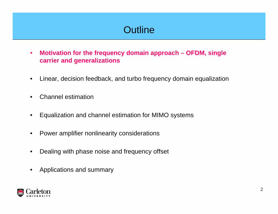
• Motivation for the frequency domain approach – OFDM, single carrier and generalizations
• Linear, decision feedback, and turbo frequency domain equalization
• Channel estimation
• Equalization and channel estimation for MIMO systems
• Power amplifier nonlinearity considerations
• Dealing with phase noise and frequency offset
• Applications and summary
3
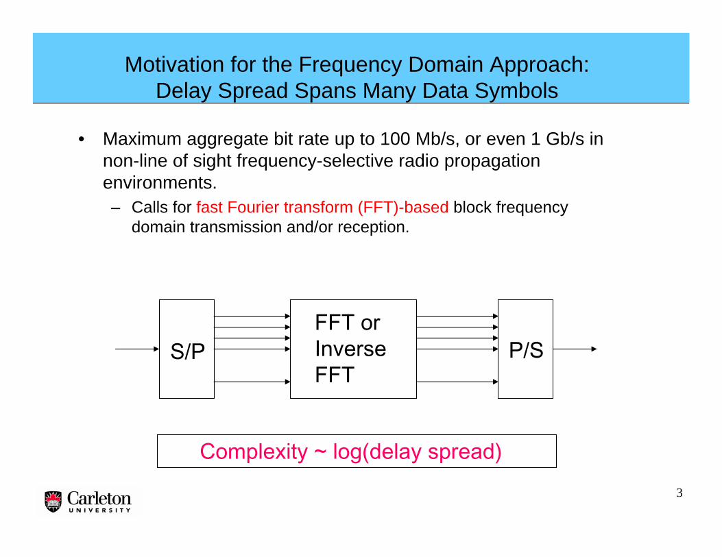
Motivation for the Frequency Domain Approach: Delay Spread Spans Many Data Symbols
• Maximum aggregate bit rate up to 100 Mb/s, or even 1 Gb/s in non-line of sight frequency-selective radio propagation environments.– Calls for fast Fourier transform (FFT)-based block frequency
domain transmission and/or reception.
S/PFFT orInverseFFT
P/S
Complexity ~ log(delay spread)
4
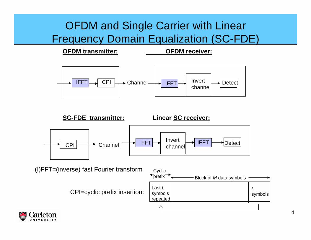
SC-FDE transmitter: Linear SC receiver:
IFFT CPI FFT Invertchannel
Detect
CPI DetectIFFT
Channel
Channel
OFDM transmitter: OFDM receiver:
OFDM and Single Carrier with Linear Frequency Domain Equalization (SC-FDE)
(I)FFT=(inverse) fast Fourier transform
CPI=cyclic prefix insertion:
FFT Invertchannel
Last Lsymbolsrepeated
Lsymbols
Block of M data symbolsCyclicprefix
5
OFDM: SC-FDE:
• Parallel transmission on multiple subcarriers →high peak-to average power ratio (PAPR)
• Very flexible, adaptive, efficient spectrum usage with OFDMA
• Powerful decoding for frequency selective channels through knowledge of each data symbol’s SINR
• Frequency offset and phase noise cause intersymbol interference in frequency domain
• Serial transmission on one carrier →low PAPR
• Less flexible spectrum usage than with OFDMA
• Powerful turbo equalization
• Frequency offset and phase noise cause easily-correctable slow-varying phase rotations on data symbols
Pr(amp.>x)
x
SCOFDM
User #1 User #2Frequency
FrequencyRef: M. Sabbaghian and D. Falconer, “Joint Turbo Frequency Domain Equalization and Carrier Synchronization”, IEEE Trans. Wireless Comm., Vol. 7, No. 1, January 2008, pp. 204-212.
6
M data symbols
Time
S/P
M-point FFT
Frequency
Frequency
Map to M out of N selected frequencies
N-point inverse FFT
P/S convert and transmit
A Generalized Multicarrier Transmission Scheme: DFT-Precoded OFDM
7
Different forms of DFT-Precoded OFDM
• Contiguous mapping → equivalent to SC-FDE with 0% rolloff sinc pulses
• Equally-spaced subcarriers, with different users frequency-interleaved →equivalent to spread-spectrum SC-FDE, with low PAPR
• Equally-spaced blocks, with different users’ blocks interleaved → not equivalent to pure SC-FDE, but with lower PAPR than equivalent OFDMA
• Frequency-multiplexed pilots → not equivalent to pure SC-FDE, but with lower PAPR than equivalent OFDMA
Freq.
Freq.
Freq.
User #1
User #2
Pilot
Freq.
8
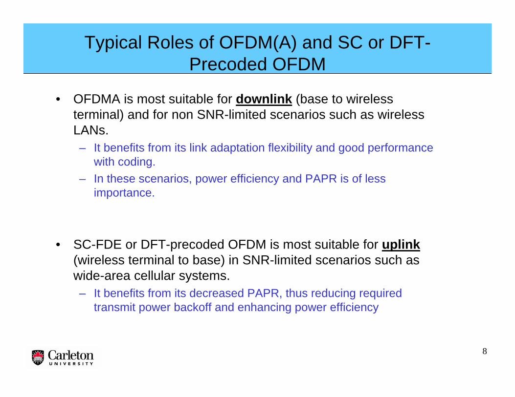
Typical Roles of OFDM(A) and SC or DFT-Precoded OFDM
• OFDMA is most suitable for downlink (base to wireless terminal) and for non SNR-limited scenarios such as wireless LANs.– It benefits from its link adaptation flexibility and good performance
with coding.– In these scenarios, power efficiency and PAPR is of less
importance.
• SC-FDE or DFT-precoded OFDM is most suitable for uplink(wireless terminal to base) in SNR-limited scenarios such as wide-area cellular systems.– It benefits from its decreased PAPR, thus reducing required
transmit power backoff and enhancing power efficiency
9
Outline
• Motivation for the frequency domain approach – OFDM, single carrier and generalizations
• Linear, decision feedback, and turbo frequency domain equalization
• Channel estimation
• Equalization and channel estimation for MIMO systems
• Power amplifier nonlinearity considerations
• Dealing with phase noise and frequency offset
• Applications and summary
10
FFTMultiplyby coeff.{Wl}
IFFT Detect
B Feedback taps {fk}
{rm} {Rl} {zm}+
-{am}
)2exp( where
)2exp(1 output DFE
1
0
*1
0
mN
jrR
afmN
jRWN
z
cu
N
mm
kmFk
kN
cuMm
cu
B
cu
l
l
l
lll
π
π
−∑=
∑−∑==
−
=
−∈
−
=
).)(E MSE (Minimize .Error 2mmmm eaze =−=
FB is a set of B feedback tap delays corresponding to the B largest channelImpulse response postcursors.
Linear and Decision Feedback Frequency Domain Equalization
Linear FDETime domain decision feedback
11
FFT
H(f)
∑ W(i)(f) ∑ IFFTIterativesoft detect/decode
FFT+ +
-
+
Iterative Block Decision Feedback Equalization (IBDFE) and Turbo Equalization (TE)
NR receive antennas NT simultaneous user data streams
a(i)(n) A(i)(f)
Subtractself- and cochannelinterferenceestimates
Restore currentsoft data estimates
Data symboloutputs
At each iteration, outputs conditional means of all users’ data symbols. For turbo equalization, includes de-interleaving, decoder extrinsic info output and re-interleaving.
12
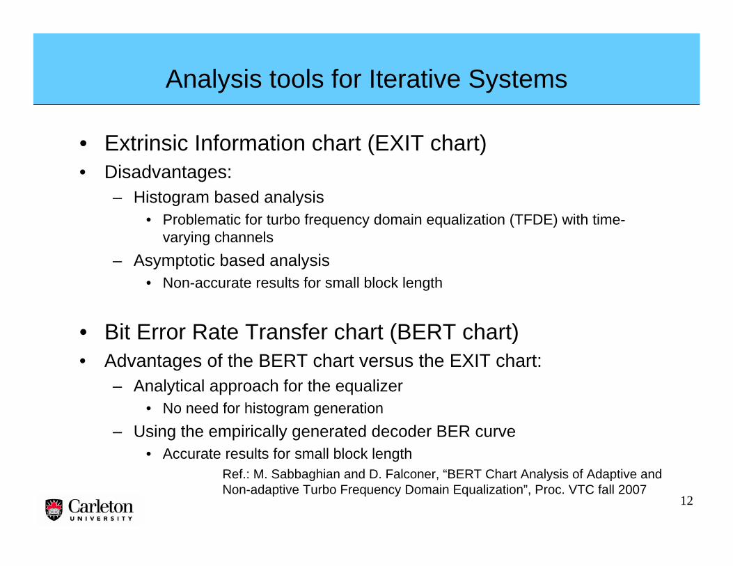
Analysis tools for Iterative Systems
• Extrinsic Information chart (EXIT chart)• Disadvantages:
– Histogram based analysis• Problematic for turbo frequency domain equalization (TFDE) with time-
varying channels– Asymptotic based analysis
• Non-accurate results for small block length
• Bit Error Rate Transfer chart (BERT chart)• Advantages of the BERT chart versus the EXIT chart:
– Analytical approach for the equalizer• No need for histogram generation
– Using the empirically generated decoder BER curve• Accurate results for small block length
Ref.: M. Sabbaghian and D. Falconer, “BERT Chart Analysis of Adaptive and Non-adaptive Turbo Frequency Domain Equalization”, Proc. VTC fall 2007
13
BERT Chart Analysis of Turbo Frequency Domain Equalizer
Wk+IFFT
FFTChannel {H}
Soft Sym. Gen.
_FFT DecoderR
R
)1( −ix
λ
Gaussian R.V.
Consistent Gaussian R.V.
||22ii m=υ
Distribution of the soft estimated symbols
),,( )1(22 −=∑ ii xHf σ
Pi
( )[ ]212|| ii PQm −=
Ref.: M. Sabbaghian and D. Falconer, “BERT Chart Analysis of Adaptive and Non-adaptive Turbo Frequency Domain Equalization”, Proc. VTC fall 2007
)1( −ix
14
Equations for Iterative Block Equalization
For FFT block size=M, noise variance=σ2 and data symbol variance=1, and for the non-adaptive case:
1,..1,0for ,22
*−=
+= Mk
H
HW
k
kk
σ
For the adaptive case:
1,..1,0for ,22
*−=
+= Mk
H
HKW
k
kk
νσ
where
∑+
=
=∑=
−
=
−
=
1
0 22
2
1
0
1
1 and
on,distributioutput decoder from computed
symbol, datath of covariance lconditiona and 1
M
m m
m
mM
mm
H
HM
K
mM
σν
ννν
15
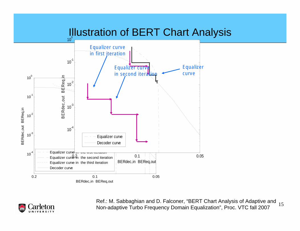
0.10.2 0.05
10-4
10-3
10-2
10-1
100
BERdec,in BEReq,out
BE
Rde
c,ou
t B
ER
eq,in
Equalizer curve in the first iterationEqualizer curve in the second iterationEqualizer curve in the third iterationDecoder curve
0.10.2 0.05
10-4
10-3
10-2
10-1
100
BERdec,in BEReq,out
BE
Rde
c,ou
t B
ER
eq,in
Equalizer curve Decoder curve
Equalizer curve
Equalizer curve in first iteration
Equalizer curve in second iteration
Ref.: M. Sabbaghian and D. Falconer, “BERT Chart Analysis of Adaptive and Non-adaptive Turbo Frequency Domain Equalization”, Proc. VTC fall 2007
Illustration of BERT Chart Analysis
16
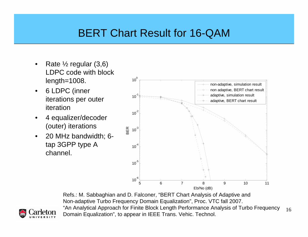
BERT Chart Result for 16-QAM
• Rate ½ regular (3,6) LDPC code with block length=1008.
• 6 LDPC (inner iterations per outer iteration
• 4 equalizer/decoder (outer) iterations
• 20 MHz bandwidth; 6-tap 3GPP type A channel.
Refs.: M. Sabbaghian and D. Falconer, “BERT Chart Analysis of Adaptive and Non-adaptive Turbo Frequency Domain Equalization”, Proc. VTC fall 2007.“An Analytical Approach for Finite Block Length Performance Analysis of Turbo FrequencyDomain Equalization”, to appear in IEEE Trans. Vehic. Technol.
• Motivation for the frequency domain approach – OFDM, single carrier and generalizations
• Linear, decision feedback, and turbo frequency domain equalization
• Channel estimation
• Equalization and channel estimation for MIMO systems
• Power amplifier nonlinearity considerations
• Dealing with phase noise and frequency offset
• Applications and summary
18
Channel Estimation
• For both time and frequency-multiplexed pilots, interpolation in frequency and time is necessary, to keep pilot overhead low.
• Pilot overhead increases for spatial multiplexing/SDMA and adaptive transmission.
• Challenges: estimation of channels with rapid time variation andwith large delay spread.
19
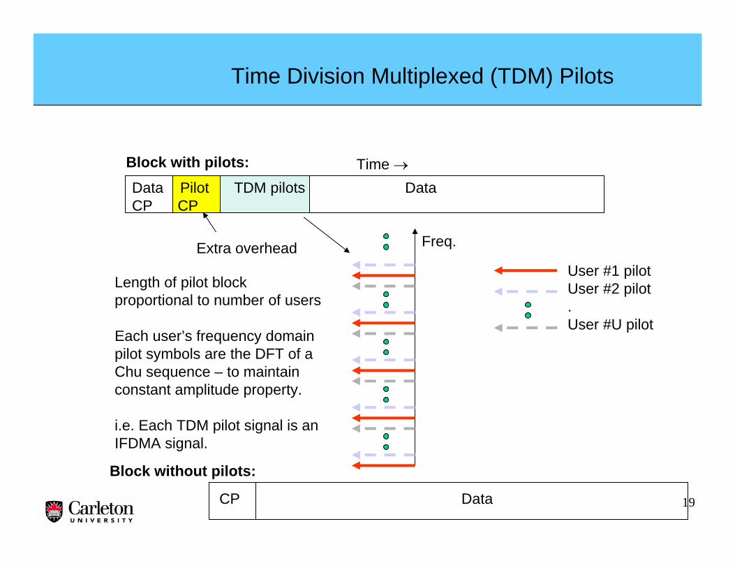
Time Division Multiplexed (TDM) Pilots
Data Pilot TDM pilots DataCP CP
CP Data
Time →
User #1 pilotUser #2 pilot.User #U pilot
Freq.
Block without pilots:
Length of pilot block proportional to number of users
Each user’s frequency domainpilot symbols are the DFT of aChu sequence – to maintain constant amplitude property.
i.e. Each TDM pilot signal is an IFDMA signal.
Block with pilots:
Extra overhead
20
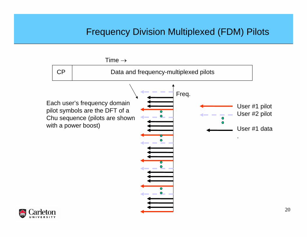
Frequency Division Multiplexed (FDM) Pilots
CP Data and frequency-multiplexed pilots
Time →
Each user’s frequency domainpilot symbols are the DFT of aChu sequence (pilots are shownwith a power boost)
User #1 pilotUser #2 pilot
User #1 data.
Freq.
21
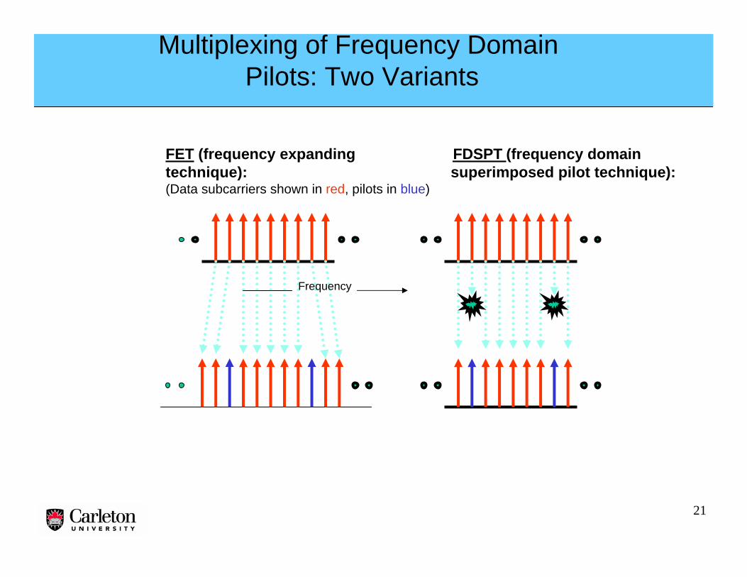
Multiplexing of Frequency Domain Pilots: Two Variants
FET (frequency expanding FDSPT (frequency domaintechnique): superimposed pilot technique):(Data subcarriers shown in red, pilots in blue)
Frequency
22
• Issue of noise enhancement due to Gaussian like frequency response of data decisions:
• Frequency replacement algorithm: replace the noise enhanced raw estimates with previouse estimates, using threshold
Iterative Channel Estimator for Serial Modulation Systems
2x1D WienerChannel
Estimator #1
FD-IBSDFE
2x1D WienerChannel
Estimator #2
FrequencyReplacement FFT
S
lH~
lY
)0(~lH
lP
lY
kb~
malA
)0(~lH De-
Interleaver
Interleaver
Decoder
Encoder
ma~
kb
FRλ
llll AVHH ˆ/ˆ +=
FRλ
23
2 3 4 5 6 7 8 9 1 0 1 1 1 2 1 31 0 - 3
1 0 - 2
1 0 - 1
1 0 0
S N R [ d B ]
FER
S M - F D E P , W 2 x 1 DT D M , W 2 x 1 DF D S P , W 2 x 1 DS M , K n o w n C S IO F D M - F D E P , W 2 x 1 DO F D M , K n o w n C S I
S c e n a r i o B :m a t c h e d t oτ m a x = 1 . 4 7 μ s , 5 0 k m / h
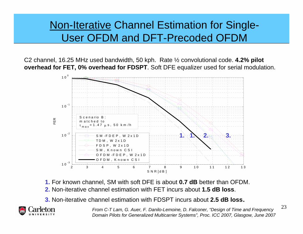
Non-Iterative Channel Estimation for Single-User OFDM and DFT-Precoded OFDM
From C-T Lam, G. Auer, F. Danilo-Lemoine, D. Falconer, “Design of Time and FrequencyDomain Pilots for Generalized Multicarrier Systems”, Proc. ICC 2007, Glasgow, June 2007
C2 channel, 16.25 MHz used bandwidth, 50 kph. Rate ½ convolutional code. 4.2% pilot overhead for FET, 0% overhead for FDSPT. Soft DFE equalizer used for serial modulation.
1. For known channel, SM with soft DFE is about 0.7 dB better than OFDM.2. Non-iterative channel estimation with FET incurs about 1.5 dB loss.
3. Non-iterative channel estimation with FDSPT incurs about 2.5 dB loss.
1. 1. 2. 3.
24
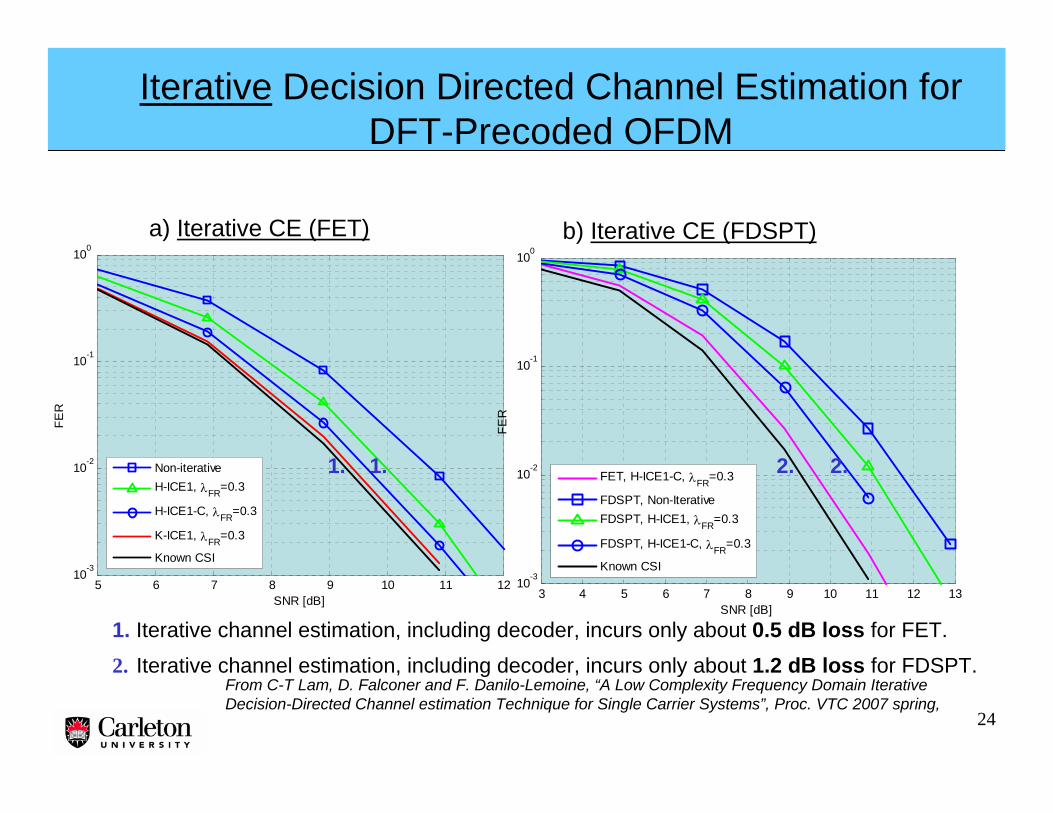
Iterative Decision Directed Channel Estimation for DFT-Precoded OFDM
a) Iterative CE (FET) b) Iterative CE (FDSPT)
5 6 7 8 9 10 11 1210-3
10-2
10-1
100
SNR [dB]
FER
Non-iterativeH-ICE1, λFR=0.3
H-ICE1-C, λFR=0.3
K-ICE1, λFR=0.3
Known CSI
3 4 5 6 7 8 9 10 11 12 1310-3
10-2
10-1
100
SNR [dB]
FER
FET, H-ICE1-C, λFR=0.3
FDSPT, Non-IterativeFDSPT, H-ICE1, λFR=0.3
FDSPT, H-ICE1-C, λFR=0.3
Known CSI
From C-T Lam, D. Falconer and F. Danilo-Lemoine, “A Low Complexity Frequency Domain Iterative Decision-Directed Channel estimation Technique for Single Carrier Systems”, Proc. VTC 2007 spring,
1. Iterative channel estimation, including decoder, incurs only about 0.5 dB loss for FET.
2. Iterative channel estimation, including decoder, incurs only about 1.2 dB loss for FDSPT.
1. 1. 2. 2.
25
Outline
• Motivation for the frequency domain approach – OFDM, single carrier and generalizations
• Linear, decision feedback, and turbo frequency domain equalization
• Channel estimation
• Equalization and channel estimation for MIMO systems
• Power amplifier nonlinearity considerations
• Dealing with phase noise and frequency offset
• Applications and summary
26
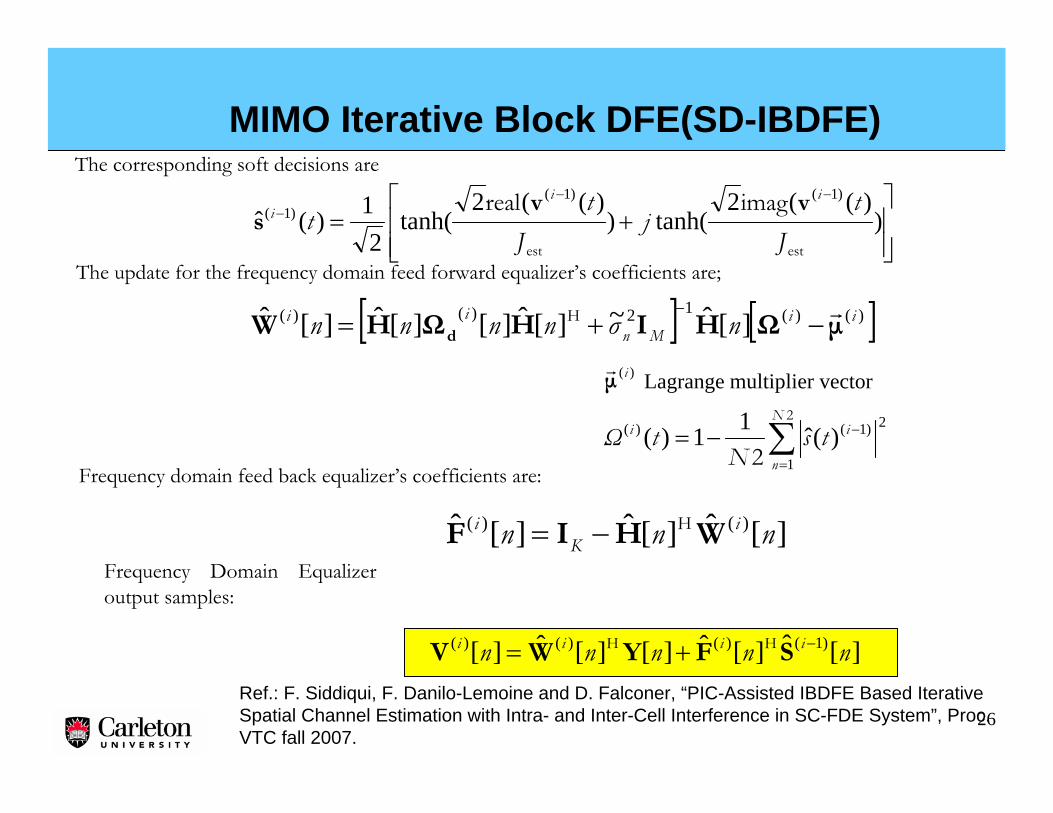
MIMO Iterative Block DFE(SD-IBDFE)
⎥⎥⎦
⎤
⎢⎢⎣
⎡+=
−−− )
)((2tanh()
)((2tanh(
21)(ˆ
)1()1()1(
estest
imagrealJ
tj
Jt
tii
i vvs
[ ] [ ])()(12)()( ][ˆ~][ˆ][][ˆ][ˆ iiMn
ii nσnnnn μΩHIHΩHW d
r−+=−H
The update for the frequency domain feed forward equalizer’s coefficients are;
Frequency domain feed back equalizer’s coefficients are:
][ˆ][ˆ][ˆ )()( nnn iK
i WHIF H−=
][ˆ][ˆ][][ˆ][ )1()()()( nnnnn iiii −+= SFYWV HH
Lagrange multiplier vector)(iμr
∑=
−−=2
2
N
n
ii tsN
tΩ1
2)1()( )(ˆ11)(
The corresponding soft decisions are
Frequency Domain Equalizer output samples:
Ref.: F. Siddiqui, F. Danilo-Lemoine and D. Falconer, “PIC-Assisted IBDFE Based Iterative Spatial Channel Estimation with Intra- and Inter-Cell Interference in SC-FDE System”, Proc. VTC fall 2007.
27
Channel Estimation: Pilot-assisted and Parallel Interference Cancellation (PIC)
• 1- Initial Pilot-based Short Estimates• Received signal:
m=1,2,…M (Antenna Element Index)n=1,2,…N2 (sub-carrier index)w=1,2,…F (Symbol index)
• Initial CE (Chu Sequences are used for Initial training) :
• 2- Full Length Channel estimates via 2x1D Interpolation
• 3- Hard Decisions after Decoding
• 4- Parallel Interference Cancellation (PIC)
i=1,2,…Ie (SD-IBDFE iteration index)j=1,2,…Iice (DFICE iteration index)The Received Array Input is:
• In-Cell Interference-free Array Input w.r.t. the Desired User k:
∑≠=
−−=K
k
ijjij lnDlnnknll ,1
),()1(),( ],[ˆ],[ˆ][],[ HYX
∑+
=
+=P
g
ggmm nNnDnHnY
1
][][][][1
wmww
((((
][][)(
nnn
D
YH (
((
=
][ˆ nH
][ˆ , nijD
][nY
∑≠=
−K
k
ijj lnDlnll ,1
),()1( ],[ˆ],[H
Ref.: F. Siddiqui, F. Danilo-Lemoine and D. Falconer, “PIC-Assisted IBDFE Based Iterative Spatial Channel Estimation with Intra- and Inter-Cell Interference in SC-FDE System”, Proc. VTC fall 2007.
28
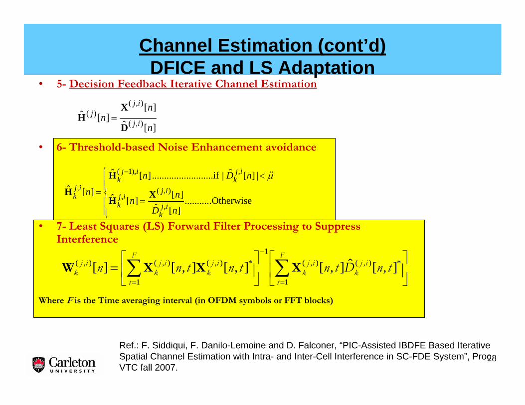
Channel Estimation (cont’d)DFICE and LS Adaptation
• 7- Least Squares (LS) Forward Filter Processing to Suppress Interference
Where F is the Time averaging interval (in OFDM symbols or FFT blocks)
⎥⎦
⎤⎢⎣
⎡⎥⎦
⎤⎢⎣
⎡= ∑∑
=
−
=
F
t
ijk
ijk
F
t
ijk
ijk
ijk tnDtntntnn
1
*),(),(1
1
*),(),(),( ],[ˆ],[],[],[][ XXXW
][ˆ
][][ˆ
),(
),()(
n
nn ij
ijj
D
XH =
⎪⎪⎩
⎪⎪⎨
⎧
=
<
=
−
.Otherwise..........][ˆ][][ˆ
|][ˆ| .....if.................... ][ˆ
][ˆ
,
),(,
,),1(
,
nDnn
nDn
nij
k
ijij
k
ijk
ijk
ijk XH
H
H
μt
Ref.: F. Siddiqui, F. Danilo-Lemoine and D. Falconer, “PIC-Assisted IBDFE Based Iterative Spatial Channel Estimation with Intra- and Inter-Cell Interference in SC-FDE System”, Proc. VTC fall 2007.
29
Simulation Signal and Channel ParameterNotations and Simulation Parameters
•PCSI: Perfect channel state information.•LE: Linear Equalization.•SD: Soft Decision.•PIC: Parallel Interference Cancellation.•ICU: In-Cell User.•OCI: Out of Cell Interferer.•DFICE: Decision Feedback IterativeChannel Estimation.
• Modulation Scheme = QPSK.• Carrier frequency = 3.7GHz.• Signal BW = 40MHz.• Sub-Carrier spacing = 39.0625kHz.• Short training blocks for time averaging (NT) = 1 or 2.• Reliability Threshold in DFICE (μ) = 13.• Independent C2-Urban Macro 20-path channel model.• BS Antenna elements = M = 2 or 4.• In- Cell Users = K = 2.• Out of Cell Interferers = P = 4.• LE and SD-IBDFE Equalization (iterations=4).• DFICE Iterations = 1 or 2.• Used sub-carriers N2 = 1024. • Mobility = 50 km./hr.• Symbols/Frame = F = 12.• First and last symbol of each 12-symbol frame contain training. • Pilots per training block = 256.• 2x1D Wiener interpolation based on max. delay spread and Doppler.
Ref.: F. Siddiqui, F. Danilo-Lemoine and D. Falconer, “PIC-Assisted IBDFE Based Iterative Spatial Channel Estimation with Intra- and Inter-Cell Interference in SC-FDE System”, Proc. VTC fall 2007.
30
2. SD-IBDFE (non-iterative CE) gives an improvement of 0.4dB over the LE, with –15dB OCIs.
4. The SNR penalty relative to PCSI is about 3 dB at 10-2 FER, for the 2 OCIs per ICU at -15 dB.
Simulation Results (cont’d) Non-iterative CE and PIC-assisted DFICE
1. With OCIs at –15dB knowing only the ICUs’ channels causes about a 0.4 dB SNR penalty relative to the case where all channels are known.
3. SD-IBDFE with iterative CE gives SNR improvement of about 1.8dB @ FER of 10e-2 over non-iterative CE.
Ref.: F. Siddiqui, F. Danilo-Lemoine and D. Falconer, “PIC-Assisted IBDFE Based Iterative Spatial Channel Estimation with Intra- and Inter-Cell Interference in SC-FDE System”, Proc. VTC fall 2007.
• LS Adaptation (not shown here) gives a further SNR improvement of 0.5 to 1 dB.
2. 1. 1. 3. 3.4. 4.
31
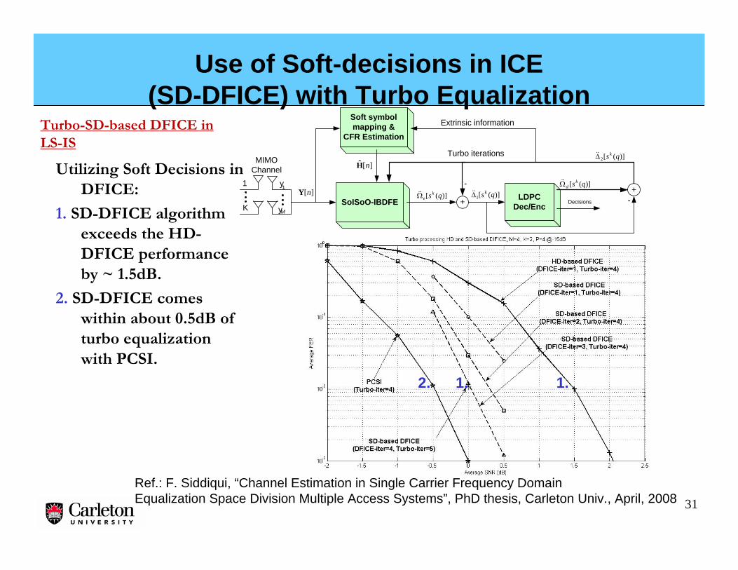
Use of Soft-decisions in ICE (SD-DFICE) with Turbo Equalization
Turbo-SD-based DFICE in LS-IS
SoISoO-IBDFE
Turbo iterationsMIMO
Channel
][nYy1
yM
1
K)]([ qsk
eΩr
LDPCDec/Enc
Decisions)]([1 qskΔ&&
+
)]([2 qskΔ&&
+)]([ qsk
dΩr
-
-
Soft symbol mapping &
CFR Estimation
][ˆ nH
Extrinsic information
Utilizing Soft Decisions in DFICE:
1. SD-DFICE algorithm exceeds the HD-DFICE performance by ~ 1.5dB.
2. SD-DFICE comes within about 0.5dB of turbo equalization with PCSI.
Ref.: F. Siddiqui, “Channel Estimation in Single Carrier Frequency DomainEqualization Space Division Multiple Access Systems”, PhD thesis, Carleton Univ., April, 2008
2. 1. 1.
32
Outline
• Motivation for the frequency domain approach – OFDM, single carrier and generalizations
• Linear, decision feedback, and turbo frequency domain equalization
• Channel estimation
• Equalization and channel estimation for MIMO systems
• Power amplifier nonlinearity considerations
• Dealing with phase noise and frequency offset
• Applications and summary
33
Power Amplifier Linearity Requirements and Cost
• The greater the modulation scheme’s peak to average ratio PAPR), the greater the required backoff, and the greater the required maximum rated power to achieve the link budget.
• HPA cost rises sharply with maximum power rating.
Input power
Outputpower
High PAPR signal
Low PAPRsignal
HPA required for high power backoff($$$)
HPA required for lower power backoff($)
At a certain max. power level(e.g. ~ 30 dBm), cost isdetermined by thermodynamics
340 0.2 0.4 0.6 0.8 1 1.2 1.4 1.6 1.8 2
0
0.2
0.4
0.6
0.8
1
1.2
p=2p=10
p=50
Input amplitude
Out
put a
mpl
itude
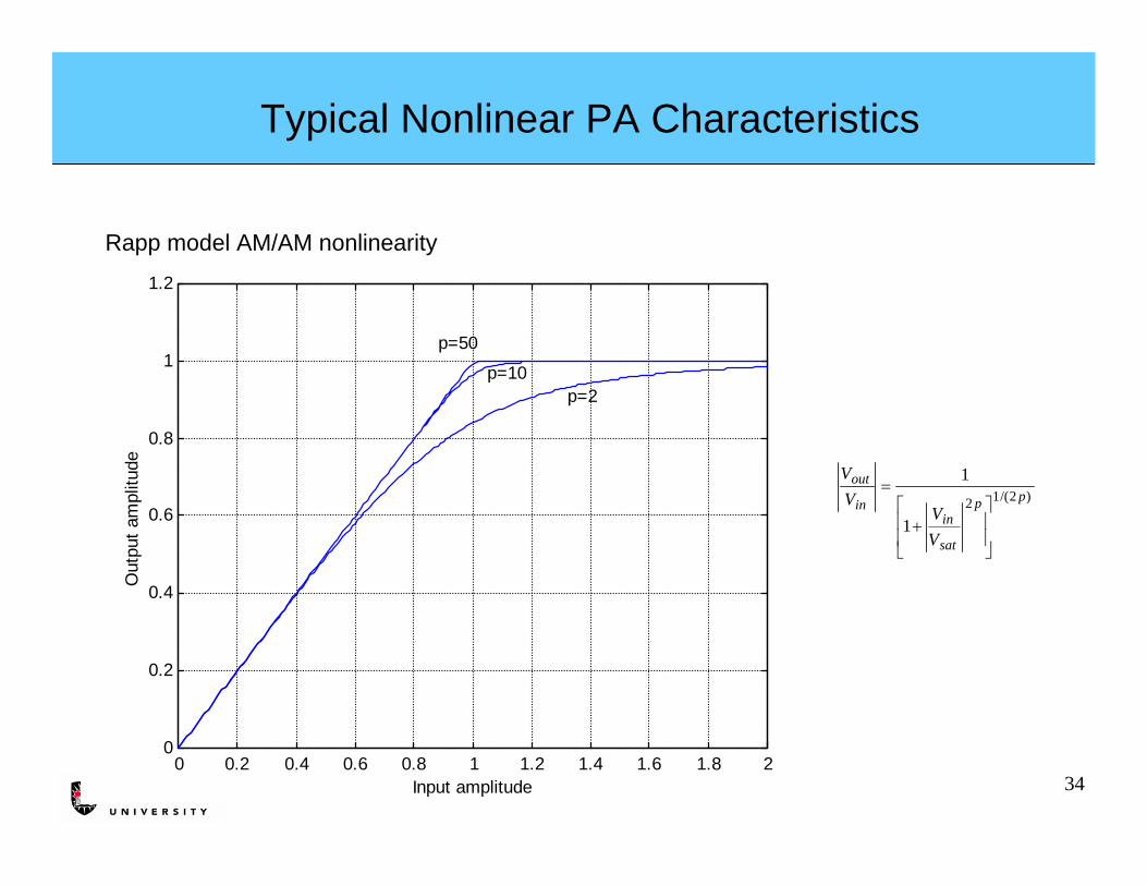
Rapp model AM/AM nonlinearity
Typical Nonlinear PA Characteristics
)2/(12
1
1pp
sat
inin
out
VV
VV
⎥⎥
⎦
⎤
⎢⎢
⎣
⎡+
=
35
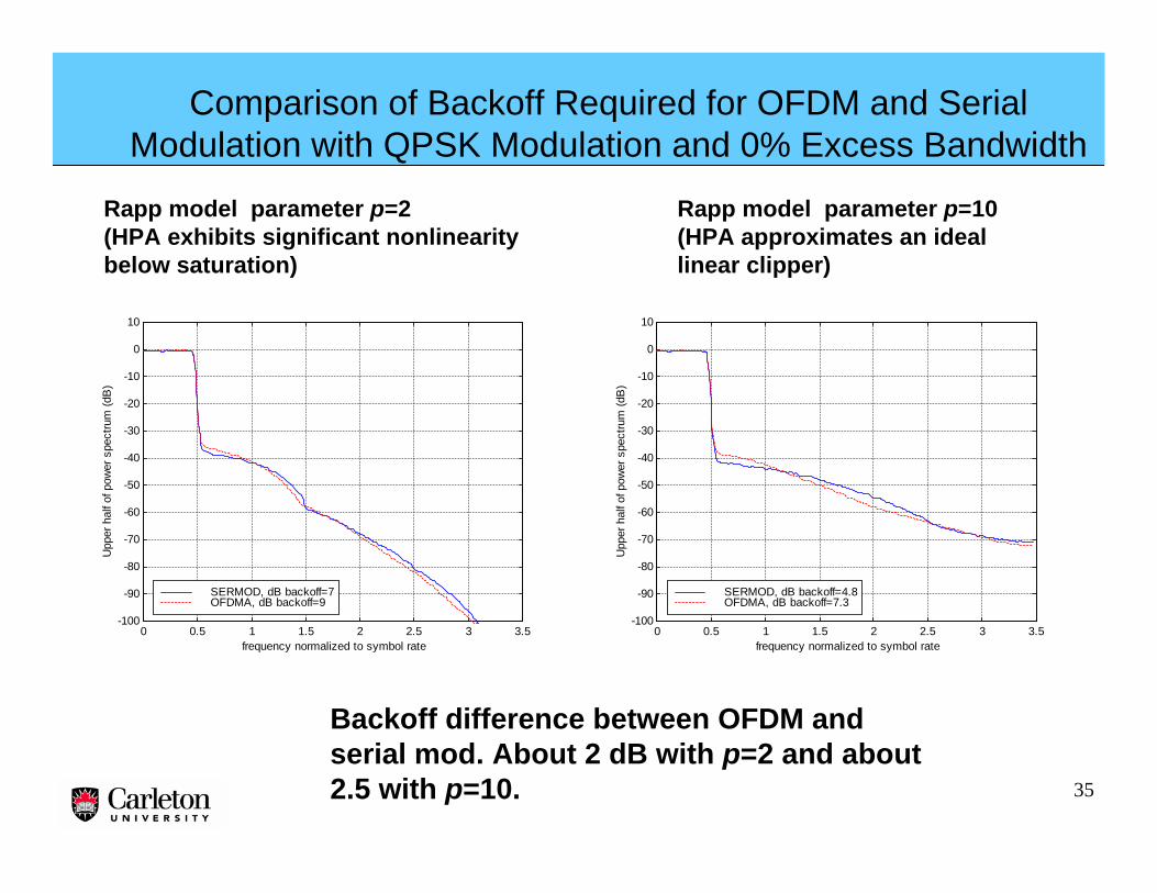
Comparison of Backoff Required for OFDM and Serial Modulation with QPSK Modulation and 0% Excess Bandwidth
Backoff difference between OFDM and serial mod. About 2 dB with p=2 and about2.5 with p=10.
Rapp model parameter p=2 (HPA exhibits significant nonlinearity below saturation)
0 0.5 1 1.5 2 2.5 3 3.5-100
-90
-80
-70
-60
-50
-40
-30
-20
-10
0
10
frequency normalized to symbol rate
Upp
er h
alf o
f pow
er s
pect
rum
(dB
)
SERMOD, dB backoff=7OFDMA, dB backoff=9
0 0.5 1 1.5 2 2.5 3 3.5-100
-90
-80
-70
-60
-50
-40
-30
-20
-10
0
10
frequency normalized to symbol rate
Upp
er h
alf o
f pow
er s
pect
rum
(dB
)
SERMOD, dB backoff=4.8OFDMA, dB backoff=7.3
Rapp model parameter p=10 (HPA approximates an ideal linear clipper)
36
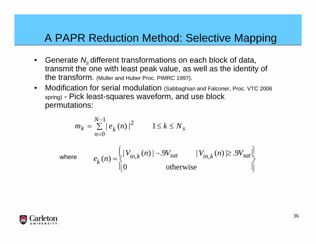
A PAPR Reduction Method: Selective Mapping
• Generate Ns different transformations on each block of data, transmit the one with least peak value, as well as the identity of the transform. (Muller and Huber Proc. PIMRC 1997).
• Modification for serial modulation (Sabbaghian and Falconer, Proc. VTC 2006 spring) - Pick least-squares waveform, and use block permutations:
∑ ≤≤=−
=
1
0
2 1|)(|N
nskk Nknem
⎪⎭
⎪⎬⎫
⎪⎩
⎪⎨⎧ ≥−
=otherwise0
9.|)(|9.|)(|)( ,, satkinsatkin
kVnVVnV
newhere
37
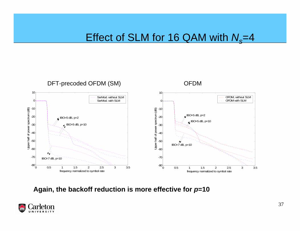
0 0.5 1 1.5 2 2.5 3 3.5-80
-70
-60
-50
-40
-30
-20
-10
0
10
frequency normalized to symbol rate
Upp
er h
alf o
f pow
er s
pect
rum
(dB
)
SerMod. without SLMSerMod. with SLM
IBO=5 dB, p=2
IBO=5 dB, p=10
IBO=7 dB, p=10
0 0.5 1 1.5 2 2.5 3 3.5-80
-70
-60
-50
-40
-30
-20
-10
0
10
frequency normalized to symbol rate
Upp
er h
alf o
f pow
er s
pect
rum
(dB
)
OFDM, without SLMOFDM with SLM
IBO=5 dB, p=2
IBO=5 dB, p=10
IBO=7 dB, p=10
DFT-precoded OFDM (SM) OFDM
Effect of SLM for 16 QAM with Ns=4
Again, the backoff reduction is more effective for p=10
38
Another PAPR Reduction Method for GMC Signals with Pilots
• Try pilot sequences from a set of Ns possible orthogonal sequences, and select the resulting composite waveform with minimum peak value (Garcia et al, IEEE Trans. Wireless Comm., Jan. 2006).
• Modification for DFT-precoded OFDM (Lam, Falconer and Danilo-Lemoine, Proc. WCNC, 2007):
– Use orthogonal cyclically-shifted Chu sequences to generate possible pilot sequences– Use least-squares selection rule.
39
0 0.2 0.4 0.6 0.8 1 1.2 1.4 1.6 1.8 2-80
-70
-60
-50
-40
-30
-20
-10
0
10
Frequency normalized to symbol rate
Upp
er h
alf o
f pow
er s
pect
rum
(dB
)
SERMOD, Ns=1SERMOD, Ns=32SERMOD, no pilotsOFDMA, Ns=1OFDMA, Ns=32OFDMA, no pilots
PAPR Reduction By Pilot sequence Selection for QPSK OFDM and DFT-Precoded OFDM (Serial Modulation)
Rapp parameter p=10 Backoff=7 dB
Again, backoff reduction is more significant for p=10.
40
Outline
• Motivation for the frequency domain approach – OFDM, single carrier and generalizations
• Linear, decision feedback, and turbo frequency domain equalization
• Channel estimation
• Equalization and channel estimation for MIMO systems
• Power amplifier nonlinearity considerations
• Dealing with phase noise and frequency offset
• Applications and summary
41
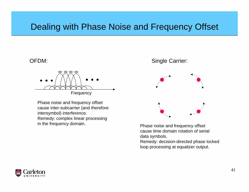
Dealing with Phase Noise and Frequency Offset
OFDM: Single Carrier:
Frequency
Phase noise and frequency offsetcause inter-subcarrier (and thereforeintersymbol) interference. Remedy: complex linear processingin the frequency domain. Phase noise and frequency offset
cause time domain rotation of serial data symbols.Remedy: decision-directed phase locked loop processing at equalizer output.
42
Phase Noise and Frequency Offset Compensation for QPSK Using Turbo-Equalized Decision-Directed ProcessingRef: M. Sabbaghian and D. Falconer, “Joint Turbo Frequency Domain Equalization and Carrier Synchronization”, IEEE Trans. Wireless Comm., Vol. 7, No. 1, January 2008, pp. 204-212.
43
Outline
• Motivation for the frequency domain approach – OFDM, single carrier and generalizations
• Linear, decision feedback, and turbo frequency domain equalization
• Channel estimation
• Equalization and channel estimation for MIMO systems
• Power amplifier nonlinearity considerations
• Dealing with phase noise and frequency offset
• Applications and summary
44
Applications of DFT-Precoded OFDM
• Single carrier is one of the three physical layer modes specified in the IEEE 802.16a and e standards, but it has not been implemented.
• 3GPP-LTE standard specifies DFT-precoded OFDM (which it calls SC-FDMA) as the uplink transmission mode.
• The recently completed EU WINNER Project recommends DFT-precoded OFDM as the uplink transmission mode for wide area FDD non-frequency adaptive uplinks in future generation wireless systems– Non-adaptive frequency diversity achieved with block-interleaved
frequency division multiple access (B-IFDMA) for uplink transmitter power efficiency.
45
Summary
• DFT-precoded OFDM, with frequency domain equalization, has an important role in the “OFDM era”.
• Iterative block and turbo equalization are powerful equalizationtechniques for DFT-recoded OFDM.– Adaptive turbo equalization, can be analyzed by the refined BERT
chart technique, even for small block lengths.• Channel estimation is aided by time- or frequency-multiplexed
pilots, and is enhanced by iterative methods.• DFT-precoded OFDM has lower PAPR and lower required
power backoff than comparable OFDM– PAPR reduction methods used for OFDM can be modified and
used effectively for DFT-precoded OFDM.• DFT-precoded OFDM (SC-FDMA) has been specified for the