AIAA 2002-0275 Recent Applications and Improvements to the Engineering-Level Aerodynamic Prediction Software MISL3 D. Lesieutre, J. Love, and M. Dillenius Nielsen Engineering & Research, Inc. Mountain View, CA A. B. Blair, Jr. Williamsburg, VA 40th AIAA Aerospace Sciences Meeting & Exhibit 14-17 January 2002 / Reno, NV For permission to copy or republish, contact the copyright owner named on the first page. For AIAA-held copyright, write to AIAA Permissions Department, 1801 Alexander Bell Drive, Suite 500, Reston, VA, 20191-4344.
Transcript
AIAA 2002-0275Recent Applications and Improvementsto the Engineering-Level AerodynamicPrediction Software MISL3
D. Lesieutre, J. Love, and M. DilleniusNielsen Engineering & Research, Inc.Mountain View, CA
A. B. Blair, Jr.Williamsburg, VA
40th AIAA Aerospace SciencesMeeting & Exhibit
14-17 January 2002 / Reno, NVFor permission to copy or republish, contact the copyright owner named on the first page.
For AIAA-held copyright, write to AIAA Permissions Department,1801 Alexander Bell Drive, Suite 500, Reston, VA, 20191-4344.
Copyright å2002 by Nielsen Engineering & Research, Inc.
Published by the American Institute of Aeronautics and Astronautics, Inc. with permission.
1American Institute of Aeronautics and Astronautics
AIAA 2002-0275RECENT APPLICATIONS AND IMPROVEMENTS TO THE
Daniel J. Lesieutre , John F. Love , Marnix F. E. Dillenius* † ‡
Nielsen Engineering and Research, Inc.Mountain View, CA 94043
A.B. Blair, Jr.§
Williamsburg, VA
ABSTRACT p,q,r rotational rates, rads/sec
Engineering-level missile aerodynamics prediction code s fin semispan measured from body centerlineMISL3 has recently been applied to a variety ofconfigurations including two tandem-control models andto a two-fin-set model with free rolling tail fins tested atNASA Langley Research Center. Enhanced capabilitiessince the earlier M3HAX version include the modelingof conical changes in body diameter (flares, boattails)and arbitrary interdigitation angles between fin sets.Results presented include high angle of attackaerodynamics, induced lateral forces, tandem-control findeflections, configurations with flares and/or boattails,estimates of free rotating fin section performance,rotational damping estimates, and updates to resultspresented in an earlier paper. Comparisons toindependent experimental data are presented todemonstrate the unique qualities of the code. InM3F3CA, earlier MISL3, MISSILE3) has beengeneral, good agreement with experimental data is developed for aerodynamic performance prediction andobtained for a variety of configurations (body alone, for preliminary design of conventional missiles. Thesingle-fin set, two-fin set, and three-fin set method uses the Triservice systematic fin-on-body forceconfigurations) and flow conditions (symmetric and and moment data base which covers a Mach numberasymmetric). range from 0.6 to 4.5, fin aspect ratios from 0.25 to 4.0,
LIST OF SYMBOLS deflection angles from -40° to 40°. The method uses thea body radius at fin mid-rootchord equivalent angle of attack concept which includes theAR aspect ratio (two fins joined at root) effects of vorticity and geometric scaling. The latestC body crossflow drag coefficientdcC rolling moment/q S ll ∞ R RC roll-damping coefficient; ∂C /∂(pl /2V )lp l R ∞C pitching moment/q S l ; positive nose upm ∞ R RC normal force/q SN ∞ RC fin normal force/q SNF ∞ RC body dC /d� at �=0N� ND body diameter, maximumL body lengthl ,L reference lengthR REF_____________________
Senior Research Engineer, Senior Member AIAA*
Research Engineer†
President, Associate Fellow AIAA‡
Aerospace Technologist, Associate Fellow AIAA§
s exposed fin span
mS reference areaRx center of pressureCPx moment centerMC� included angle of attack, degc fin deflection angle, deg� fin taper ratio- roll angle, deg- interdigitation angle of fin set 2 (tail) withF2
respect to the first fin section, deg
INTRODUCTION
The engineering-level missile aerodynamic predictioncode MISL3 (earlier versions are M3FLR, M3HAX,1 2,3
4 5 6
4,7
angles of attack up to ±45°, arbitrary roll angles, and
program described here is designated MISL3. Program1
MISL3 has been developed by extending the previouscodes to model conical changes in body diameter (flares,boattails) and to allow arbitrary interdigitation anglesbetween fin sets. This, in combination with the roll ratecapability of the code, allows estimation of theperformance of configurations with rolling fin sets. Inaddition, the paper publishes experimental data for aTandem-Control model tested by co-author Blair (nowretired) at NASA Langley Research Center(NASA/LaRC). Predicted results from MISL3 arecompared to these data.
The range of parameters allowed by program MISL3 issummarized in Table 1 below.
Two Fin Set Canard ControlSingle Fin Set Tail Control
Two Fin Set Planar Wing/Cruciform Tail Three Fin Set
2American Institute of Aeronautics and Astronautics
Flow Conditions: 0.5 ≤ M ≤ 5.0 -90° ≤ � ≤ 90°∞ carbitrary roll angle - -40° ≤ ≤ 40°
arbitrary rotational rates (p,q,r)user-specified nonuniform flow field
Geometries:0.25 ≤ AR ≤ 10.0 0.0 ≤ � ≤ 1.0
up to three finned sections 1 to 4 fins per finned sectionidentical fins within a section symmetrical airfoil sectionsno fins with forward sweep no fin trailing edge sweep
arbitrary interdigitation between fin sets
Table 1. Range of Parameters
Some examples of configurations addressable by MISL3are shown in the next sketch.
The technical approach section of this paper summarizesthe calculation procedures included in the MISL3program and describes the recent modelingimprovements. The experimental and analytical databases used within the MISL3 program are described inRefs. 3 and 7. Extensive comparisons are presented toindependent experimental data for a variety ofconfigurations and flow conditions, and conclusions andacknowledgements are given.
TECHNICAL APPROACH
This section summarizes body and fin force and momentcalculations and describes recent improvements to themethodology employed in MISL3.
BODY FORCE AND MOMENTCALCULATIONS
This section describes the body load calculation. MISL3improves the body modeling of M3HAX by allowing2,3
conical changes in body diameter (flares and/orboattails). The potential and crossflow drag approachdescribed in Ref. 2 is employed and summarized here.To determine the loads acting on the body, the body isdivided into segments. The load on each segment, i, isdetermined including effects due to freestream, angularrates, and nonuniform flow fields. Potential normalforce contributions are computed whenever dr /dx orid� /dx are nonzero. The body radius slope dr /dx willi ibe nonzero on the body nose and on any flares orboattails. The axial variation in local flow angle of
attack or sideslip will be nonzero whenever there arerotational rates or nonuniform flow field effects.
Angular Rates and Nonuniform Flow Field Effects.In order to include the effects of angular rates and anonuniform flow field, the body is divided into nose,flare/boattail, fin, and afterbody sections. Each of thesesections is divided into segments. Control points arefixed at the midpoints of each segment (on the centerlineof the body). The local velocity induced by the angularrates is found for each segment control point by takingthe cross product of the rotational rate vector (p,q,r) andthe body control point position vector as measured fromthe rotation center. Normalized perturbation velocitiesat the body segment control points from a nonuniformflow field are added to the normalized angular rateinduced velocities. The nonuniform flow field velocitiesare user-supplied. Forces and moments are calculatedfor each segment along the length of the body using thedifferential form of the equations developed byJorgensen shown below.8
Potential Component of Body Load Calculation. Thepotential part of the normal force on the body is givenin differential form by:
(1)
where r is the body radius at the control point, r is thei bradius of the missile base, dr /dx is the body slope at theicontrol point, and � is the local angle of attack for theisegment determined from the sum of the freestream,angular, and nonuniform flow field velocities normal tothe missile centerline. A similar equation can be writtenfor the potential side force. Lift curve slope C is userN�input (usually set equal to 2.0).
Crossflow Drag Component of Body LoadCalculation. If the freestream angle of attack is greaterthan 4°, the flow may separate. The axial location ofthe point of separation is determined from empiricalrelationships. The crossflow drag contribution to5
normal force, in differential form, is calculated asfollows for all control points aft of the point ofseparation:
(2)
3American Institute of Aeronautics and Astronautics
where C is the crossflow drag coefficient and � is experimental data are made for a variety ofdc2,8
a correction factor for finite body length. Both are a configurations, including: body-alone, single-fin set,2,9
function of crossflow Mach number, M sin� . To two-fin set, and three-fin set configuration. In addition,∞ ccompare to sting-mounted wind tunnel models, thecorrection factor � should be set to 1.0.
FIN FORCE AND MOMENT CALCULATION
This section summarizes the fin force and momentcalculation and the equivalent angle of attackmethodology. References 2 and 3 provide a completedescription of this methodology. The primaryimprovement in the new MISL3 code is the ability to Results are also presented for several configurationshandle arbitrary interdigitation angles between fin sets.presented originally in Ref. 10. In that reference, resultsThis modification affects the orientation of aft fin setsto upstream vorticity and the resolution of predictedforces into the appropriate coordinate systems.
VORTEX MODELING IN MISL3
There are three nonlinear vortex models contained inMISL3. The forebody vortex model is used to obtainAND AFT FLARE CONFIGURATIONS1-4
the vortex field influencing the first fin set. A finvortex model is required to shed the vorticity from Figure 1 compares predicted and measured results forupstream fin sets which influence the loads on aft fin four configurations: 1) cone-cylinder, 2) cone-cylindersets, and an afterbody vortex shedding model is required with four tail fins, 3) cone-cylinder with eight tail fins,to shed and track all vorticity along the body betweenfin sets. These models are described in detail in Refs. 2through 4. For MISL3, the body vortex shedding and two (2) cruciform fin sets on top of one another withtracking model has been modified to include the effectsone set rotated 45° from the other. Overall normalof the nonuniform flow field and rotational rates. This force, pitching moment, axial force, and center ofamounts to including a doublet term which accounts forpressure are shown. The increments in aerodynamicthe local nonuniform flow and rotational rate effects atcharacteristics between these configurations are predictedeach body segment. In addition, two-dimensionalreasonably well. The normal force on the cone-cylinder-sources/sink have been added to the vortex trackingflare configuration is overpredicted; it is underpredictedprocedure to ensure that vortices are pushed out over an at low angles of attack for the three other configurations.expanding flare section and pulled in over a decreasing The axial force is predicted well.radius flare/boattail section. An example of a vortexfield obtained with the MISL3 code is shown in theresults section.
AXIAL FORCE PREDICTION
The axial force prediction methodology in MISL3 issemi-empirical and has been described previously.2,4
The following components contribute to the overall axialforce: skin friction, subsonic pressure, transonicpressure/wave, supersonic wave, body base, fin trailingedge base, fin deflection, and angle of attack induced.
RESULTS
This section presents longitudinal and lateral-directionalaerodynamic predictions obtained with the MISL3prediction software. Comparisons of the results to
the capability of MISL3 to predict lateral-directionalaerodynamic characteristics for asymmetric flowconditions and fin deflections is also illustrated.Comparisons of predictions to the Tandem-ControlModel data base are presented. The effects ofinterdigitation between fin sets is analyzed along withthe estimation of tail fin section roll rate for a canard-tail configuration with a free-rolling tail section.
were obtained with M3FLR. The results shown in thispaper reflect corrections to geometry input, body liftcurve slope C (Eqn. 1), and crossflow drag correctionN�factor � (Eqn. 2). Unless otherwise noted, C = 2.0N�and � = 1.0 for all predicted results.
BODY-ALONE, 4 TAIL FINS, 8 TAIL FINS,
11
and 4) cone-cylinder with a flare. In MISL3, the eighttail fin configuration is approximated by superimposing
SINGLE-FIN SET CONFIGURATION
Predicted and measured results are presented in12
Figures 2, 3, and 4 for a body-tail configuration with asmall boattail. The body consists of a 3-caliber ogivenose, a 9.53-diameter cylindrical body, and a 0.53-diameter 4° boattail section. The tail fins have a bodyradius to fin semispan ratio, a/s , of 0.4, an aspect ratiomof 1.52, and a taper ratio of 0.42.
MISL3 (formerly M3FLR) results for this configurationwere presented first in Ref. 10. These results wereinfluenced by a fin geometry error and by the bodyforce calculation parameters, C and �.N�
Figure 2 depicts measured and predicted results for- = 0°, Mach numbers of 1.60 and 2.86, and tail pitch
4American Institute of Aeronautics and Astronautics
deflections of 0 and 10°. The normal force The axial force is predicted well. The effects of thecharacteristics are predicted reasonably well. There isan underprediction in the moderate angle of attackrange, 5 to 15°. The pitching moment characteristicsare predicted well with a maximum center of pressuredifference of approximately one body radius. The axialforce characteristics are predicted well.
Figure 3 shows measured and predicted results for aMach number of 2.86, a roll angle of 45°, and pitchdeflection of 0 and 10°. The results are similar to the- = 0° results. The normal force is underpredicted inthe moderate angle of attack range. The center ofpressure is within 0.75 body radius, and the axial forceis predicted well.
Figure 4 shows measured and predicted tail fin loadsM = 2.86 with 0 and 10° pitch deflection. Results are∞shown for three fin positions: 1) 45° to the leeward side,2) horizontal position, and 3) 45° to the windward side.The results for the fin in the 45° to leeward position arein excellent agreement with the measured results. Thenonlinearity in fin loads for this position are due to bodyvortices on the leeward-side of the body. The horizontaland windward position results agree well for zerodeflection but are underpredicted for 10° pitch control.
SINGLE-FIN SET CONFIGURATIONWITH BOATTAILS
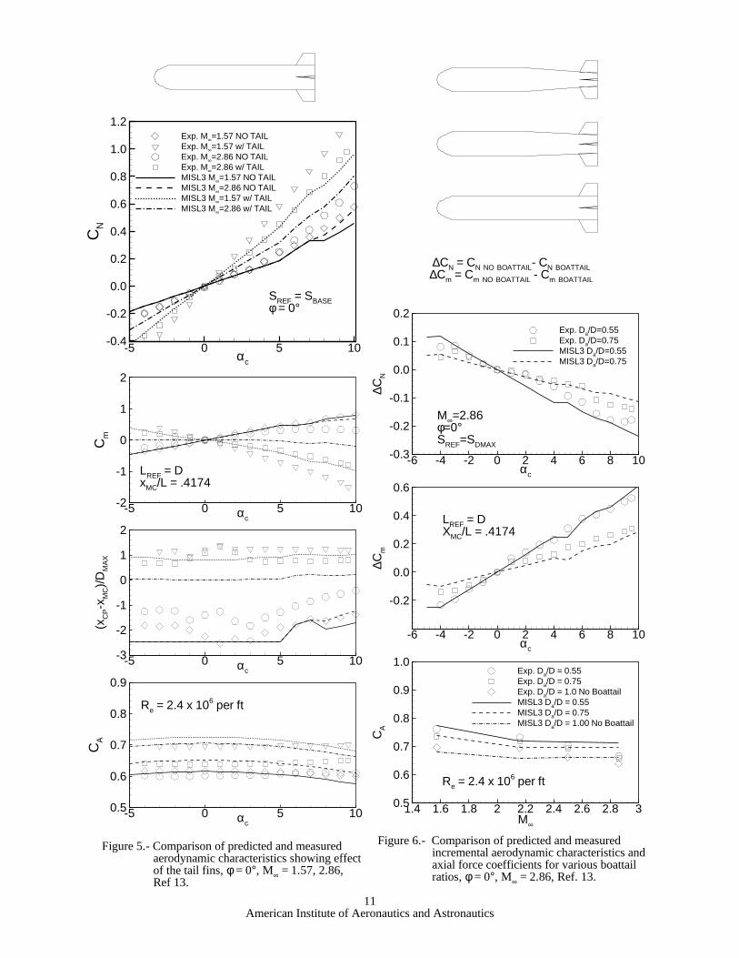
Predicted and measured results are presented in13
Figures 5 and 6 for body-tail configurations with andwithout boattails. The body consists of a 0.62-caliberblunted cone nose and a total afterbody length 6.01diameters based in the maximum body diameter. Forthe two configurations with boattails, the cylindricalcenter body is 3.01 diameters and the boattail section is3.00 diameters. The ratio of the base diameter to themaximum diameter is 0.75 and 0.55 for the boattailconfigurations.
Figure 5 depicts results for the cylindrical afterbody (noboattail) with and without tail fins. Results are shownfor - = 0° and Mach numbers of 1.57 and 2.86. Thetrends of the aerodynamic characteristics are predicted,but the magnitudes are underpredicted for thisconfiguration.
Figure 6 depicts the increment in normal force andpitching moment due to the two body boattailconfigurations with tail fins relative to the cylindricalafterbody configuration with fins. Also shown inFigure 6 is the comparison of axial force for the threetail fin configurations as a function of Mach number.
boattails are predicted well by MISL3.
THREE-FIN SET CONFIGURATION WITHBODY FLARES AND INTERDIGITATION
Figure 7 shows the three-fin-set configuration ofRef. 14. The body consists of a blunt nose shapefollowed by a cylindrical body section with a cruciformfirst fin section. Aft of the first fin set there is a smallflare section followed by a cylindrical body section.There is a second flare section immediately in front ofthe second fin set. The second fin set is on a cylindricalbody section. This is followed by a larger flare sectionand another cylindrical body section. A third fin set islocated at the base. The second and third fin sets areinterdigitated 45° relative to the first set. The planformshape of fins in fin sets 1 and 2 were idealized to satisfythe zero trailing-edge sweep constraint in MISL3.Predicted and measured results for a Mach number of14
1.82 are shown in Figure 7. Overall normal force,pitching moment, center of pressure, and axial force areshown. In general, the results indicate good agreementwith the measured data. The center of pressure ispredicted to within a body diameter. Some of the axialforce characteristics with angle of attack are notpredicted as well.
Figure 8 shows measured and predicted results for a15
configuration consisting of a high aspect ratio planarwing (AR = 4.76), horizontal tail surfaces (AR = 3.64),and a single vertical tail mounted on an ogive cylinderbody. Details are given in Ref. 15. Overall normalforce, axial force, and center of pressure are shown fora Mach number of 0.6. This configuration exercisesseveral extensions within MISL3: 1) high aspect ratio, 2)high angle of attack, and 3) the ability to model lessthan four fins per fin set. The normal force and centerof pressure are predicted well by MISL3 with someunderprediction in the 20° to 40° angle of attack range.The axial force is predicted reasonably well with theexception at 10° and above 45°.
TWO-FIN SET CONFIGURATION,TANDEM CONTROL
Tandem-Control Model Experiment. Tandem-Controldata presented in this section were obtained from testsconducted in the NASA/LaRC Unitary Plan WindTunnel at free-stream Mach numbers from 1.75to 2.86. The test objective was to provide an16
aerodynamic database to study and evaluate tandem
5American Institute of Aeronautics and Astronautics
control as a concept and to exercise aerodynamicprediction codes on a generic canard and/or tailcontrolled research missile model. Test data includedboth canard and tail surfaces that operated eitherseparately or together with only pitch control deflectionsettings.
The model had a tangent-ogive nose of finenessratio 3.0, a smooth cylindrical body, and cruciforminline canards and aft tail fins. Tests were performed ontwo models. Both models had the same canard fins.The first model had larger span tail fins, and the secondmodel had smaller tail fins identical to the canard fins.Model aerodynamic forces and moments were measuredwith an internally mounted six-component strain-gagebalance. To assure turbulent flow over the model alltests were performed with boundary-layer transitionstrips located on the model nose and near the leadingedges of the canard and tail fins. The test Reynoldsnumber was 2.0 million per foot.
Figure 9 shows measured and predicted results for the16
Tandem-Control Model described above. The modelconsists of a 3-caliber ogive nose followed by a 12-caliber cylinder. The canards fins have an aspect ratioof 1.6 and a taper ratio of 0.625; the tail fins have anaspect ratio of 2.33 and a taper ratio of 0.625. Both thecanards and tails can be deflected. Figure 9 depicts theconfiguration and presents results for M = 1.75 and∞- = 0°. Results are shown for four sets of horizontalfin deflections:
The zero deflection case is a reference. Cases 2) and 3)are deflections for translation, and Case 4) is deflectionfor rotation in pitch. The normal force, pitchingmoment, center of pressure, and axial force are allpredicted very well by MISL3. The nonlinearcharacteristics of the pitching moment are predicted byMISL3, and the center of pressure predicted is within abody radius of the measured values. The axial forcecharacteristics are also predicted well.
Figure 10 shows measured and predicted results for16
the Tandem-Control model described above. The resultsin Figure 10 are for the configuration with canard andtail fins which are identical; aspect ratio of 1.6 and ataper ratio of 0.625. Figure 10 depicts the configurationand presents results for canard pitch control forM = 1.75 and - = 45°. This case is shown because of∞the nonlinearities in the pitching moment which arise in
the “X” orientation from canard vortices affecting thetail fins. MISL3 does a good job of predicting thenonlinear pitching moment characteristics, and predictsthe overall center of pressure to within a body radius forthis configuration.
Figure 11 shows measured and predicted results for16
M = 2.5 and - = 0° with pitch (rotation) deflections.∞Results are shown for four sets of horizontal findeflections:
The overall normal force, pitching moment and axialforce characteristics are predicted well. The measurednonlinear characteristics of the pitching moment areindicated by the MISL3 predictions. The predictedcenter of pressure is within one body radius of themeasured value.
TWO-FIN SET CONFIGURATION WITHFREE-ROLLING TAIL SECTION
Figures 12, 13, and 14 present results for a canard-tailmissile model. Results for three test configurations17
are presented. For all configurations, the canards are inthe - = 0° orientation (“+” orientation, designatedF1C+). Three tail section orientations were tested:
The C+Tx configuration is depicted in Figures 12, 13,and 14. The model has a 3-caliber tangent-ogive noseand an overall body length of 15 diameters. The testReynolds number was 2.0 million per foot.
The purpose of comparing to this experimental data wasto investigate the predictive capabilities of the MISL3code and to gain insight into the aerodynamiccharacteristics of configurations with rolling tailsections. In this investigation, the MISL3 code was usedto: 1) estimate the static roll characteristics on the tailsection under the influence of asymmetric canardvortices arising from roll control deflections, 2) estimatethe roll damping characteristics of the tail section as afunction of angles of attack, and 3) estimate the roll rateof the free-to-rotate tail section as a function of angle ofattack.
6American Institute of Aeronautics and Astronautics
Figure 12 compares measured and predicted pitchupwards. There is still an asymmetric flow field which17
plane aerodynamic characteristics for a Mach numberproduces a negative tail section rolling moment for bothof 1.7 with the horizontal canards deflected for rollcontrol, = -5° ( = ( - )/2).ROLL ROLL C2 C4Measured and predicted results are shown for the C+T+and C+Tx configurations. In addition, the measureddata for the C+T-free configuration are also shown.The normal-force coefficient is predicted well for theC+T+ configuration. MISL3 underpredicts thecharacteristics of the C+Tx configuration. The C+T+pitching moment is in good agreement. The C+Txpitching moment is overpredicted. The center ofpressure is predicted within one body radius for bothconfigurations except for small load conditions near� = 0°. The axial force is predicted well. Thecmeasured characteristics of the C+T-free configurationfall between the C+T+ and C+Tx characteristics.
Figure 13 compares measured and predicted rollingmoment characteristics for the C+T+ and C+Txconfigurations with canard roll control, = -5°. InROLLaddition, the direct canard rolling moment predicted byMISL3 is compared to the C+T-free measured results.The free-to-rotate tails do not pass a rolling moment tothe main balance, except through bearing friction forceswhich are very small. It is seen in Figure 13 that thepredicted direct roll control is in very good agreementwith the measured C+T-free rolling moment. Inaddition, the rolling moments predicted for the C+T+and C+Tx configurations agree well with data up to 4°angle of attack and have the correct trends above 4°.
The rolling moment is difficult to predict because it isdominated by the canard and body shed vorticesinfluencing the tail fins. This is the classical inducedroll. For these configurations, the induced tail finrolling moment opposes the direct canards control andactually causes the rolling moment to be negative.
Figure 14 depicts the predicted crossflow velocity fieldsat the leading edge of the tail fin section for angles ofattack of 0, 4, 8, and 12°. For � = 0°, Figure 14(a), itcis seen that the canard vortices produce acounterclockwise swirling flow which produces thenegative induced rolling moment on the tail fin sectionas seen in Figure 13. For � = 4°, Figure 14(b), theceffects of the vortex shed from the right canard vortexis not apparent because it is lightly loaded(� + = -1°). There is a stronger vortex on the leftc C2side corresponding to � + = +9°. The flow fieldc C4is asymmetric and results in a negative induced tail finsection rolling moment. The results for � = 8°,cFigure 14(c), show a large vortex from the left canardand a weaker one from the right canard. The higherangle of attack results in the vortices tracking further
the C+T+ and C+Tx configurations. Figure 14(c) alsoindicates the beginning of the body shed vorticitymodeled by MISL3.
When � = 12°, Figure 14(d), the canard vortices havectracked to positions above the tail fin region, andsignificant body shed vorticity is present. The inducedrolling moment on the tail fin section is small for thisangle of attack for both the C+T+ and C+Txconfigurations, but it has a positive slope, Figure 13.Above 12° angle of attack, the predicted induced rollingmoment from the tail fins is positive. The experimentaldata shows this behavior to a lesser extent. In theprediction, this arises from the asymmetric bodyvorticity (produced due to asymmetric canard vorticity).The left-side body vorticity is weaker than the right-side;the result is an induced positive roll on the tail fins forboth the C+T+ and C+Tx configurations. This issimilar, but opposite, to the results at lower angles ofattack with asymmetric canard vortices. Further insightis gained from these crossflow velocity predictionswhen the variation of tail section rolling moment as afunction of interdigitation angle is discussed later in thissection in connection with Figure 15(a).
MISL3 can be used to estimate the aerodynamiccharacteristics of the rolling tail section including tailsection roll rate as follows. The roll equation of motionfor the tail section as a function of time t is:
T = T (t) + T (t) + T (t) = I (dp/dt) (3)AF AD BF X
where T is torque, I is the roll moment of inertia of theXtail section, and the subscripts designation are:
The time-dependent aerodynamic forcing torque on thetail fins, T (t), is caused by the aerodynamic fin forcesAFwhich are dependent on the angle of attack and the finsection roll angle, - . The aerodynamic dampingF2torque, T (t), is dependent on the tail section roll rateADand the angle of attack. The third torque, T , can beBFused to model bearing friction and/or braking torque.The effects of braking torque and the simulation of thetail roll behavior through integration of the Eqn. (3) willbe addressed in a future effort.
Because the current version of MISL3 does not integratethe roll equation of motion of the free-to-rotate tailsection, the characteristics must be estimated based onstatic characteristics and calculated roll damping
7American Institute of Aeronautics and Astronautics
characteristics. The analysis of Falanga is followed. The tail fin roll rate is then estimated as -C /C18
For steady-state conditions (constant roll rate, no (Eqn. (6), and converted to rpm) and is shown invariance with - ), the sum of the moments must be Figure 15(d). While the magnitude of the roll rate isF2zero.
$moments = M + M + M = 0 (4)AF AD BF
Substituting M = C q S l andAF l ∞ R RM = C (pl /2V )q S lAD lp R ∞ ∞ R R
into Eqn. (4) and solving for the roll rate p, yields:
(5)
For cases where the bearing torque is much smaller thanthe aerodynamic torque, the roll rate can be estimated asfollows:
(6)
For a high quality bearing, this assumption is valid.
For the canards deflected *5° for roll control (ROLL),Figure 15(a) shows the predicted static rolling-momentcoefficient of the tail fin section as a function of tail finset roll angle - . Results are shown for angles ofF2attack of 0, 4, 8, and 12°. It is seen that the tail finrolling moment is negative (right fin up) for angles ofattack below 8°. This is apparent in the flow fieldpredictions shown in Figures 14(a)-14(c) which showpartially counterclockwise flow fields for � = 0 and 4°.cAbove 4° angle of attack, a significant cyclic variationin C develops, Figure 15(a). For 12°, the rollinglmoment variation is cyclical and changes sign. Theslope of C with respect to - at the zero crossings isl F2such that the tail section would “lock-in” to a zero rollrate. These zero crossings occur at approximately 45°intervals.
In order to estimate the tail fin roll rate using Eqn. (6),C and C must be estimated. C is estimated as thel lp lmean C with respect to - (see Figure 15(a)). Thisl F2mean C is plotted as a function of angle of attack inlFigure 15(b). The roll damping coefficient, C , islpestimated by running MISL3 with a nonzero roll rate(tail fins only) and computing C by finite difference.lpIt was found that C was constant for the range of rolllprates under investigation (that is, C is linear withlrespect to p). However, there is a dependence on angleof attack as shown in Figure 15(c).
l lp
underpredicted, the trends are predicted well. MISL3predicts that the mean C in Figure 15(b) becomeslpositive above 12° angle of attack. However, thecharacteristics of the rolling moment predicted withrespect to - are such that the tail fins “lock-in” to aF2zero roll rate around 12°. The experimental resultsindicate that this happens at 14°. The MISL3 results aredependent on the prediction of mean C and C for thel lptail section. These quantities are difficult to predictaccurately, especially when they are influenced byupstream asymmetric vorticity. The sensitivity of theestimated quantities to various parameters should bestudied further.
It is seen that MISL3 provides a reasonable estimate ofthe roll rate characteristics of a free-to-roll tail sectionunder the influence of the asymmetric flow fieldassociated with canard roll control as a function of angleof attack.
CONCLUSIONS
A fast and efficient aerodynamic prediction program,MISL3, has been developed for missiles at speeds up toM = 5 and at angles of attack up to 90°. The code is∞applicable to configurations with up to three fin sections.The body can have conical changes in diameter aft ofthe nose. Configuration roll angle and interdigitationangle between fin sets are arbitrary. The MISL3 codecan also include effects of angular rates and nonuniformflow fields. The basic underlying methodology includesa systematic fin-on-body data base, the equivalent angleof attack concept, models for the nonlinear effects of finwake and body-shed vorticity, and analytical extensionsfor geometric and flow conditions outside the range ofapplication of the fin-on-body data base.
This paper describes new and unique applications toconfigurations with tandem controls and a free-rollingtail section as well as to conventional airframe shapes.The extensive comparisons to experimental aerodynamicdata include longitudinal and lateral aerodynamiccharacteristics. In general, the predicted aerodynamiccharacteristics are in good to excellent agreement withthe experimental data. On the basis of the comparisonsdescribed in this paper, the MISL3 code should be usedby applied aerodynamicists involved in preliminarydesign of conventional missile airframes as well asdesign of missiles with advanced controls and specialfeatures such as a rolling tail section.
8American Institute of Aeronautics and Astronautics
ACKNOWLEDGMENTS 10. Packard, J. D. and Miller, M. S., “Assessment of
The MISL3 missile aerodynamics prediction code is thelatest development of a set of codes (MISSILE1, etc.)originally funded by ONR in 1972. Later versions werefunded by NAVAIR. After NEAR used its own IR&Dto develop its proprietary version, NAWCWPNSlicensed the resulting code with special addedfunctionalities. NEAR gratefully acknowledges Mr. E.L. Jeter, Code 476F00D NAWCWPNS China Lake, CA,for his continued support of the MISL3 code. NEARwould also like to thank Mr. Jerry M. Allen ofNASA/LaRC for his assistance in obtaining theTandem-Control wind tunnel data.
REFERENCES
1. Lesieutre, D. J., Love, J. F., and Dillenius, M. F.E., “MISL3-November 2000 Aerodynamic Analysisfor Finned Vehicles with Axisymmetric Bodies,”NEAR TR 561, Nov. 2000.
2. Lesieutre, D. J., Love, J. F., and Dillenius, M. F.E., “High Angle of Attack Missile AerodynamicsIncluding Rotational Rates - Program M3HAX,”AIAA 96-3392, Jul. 1996.
3. Lesieutre, D. J., Love, J. F., and Dillenius, M. F.E., “M3HAX Aerodynamic Analysis for FinnedVehicles with Axisymmetric Bodies,” NEAR TR493, Feb. 1996.
4. Lesieutre, D. J., Dillenius, M. F. E., and Whittaker,C. H., “M3F3CA Aerodynamic Analysis for FinnedVehicles with Axisymmetric Bodies,” NEAR TR424, May 1991.
5. Lesieutre, D. J., Mendenhall, M. R., Nazario, S. M.,and Hemsch, M. J., “Prediction of the AerodynamicCharacteristics of Cruciform Missiles IncludingEffects of Roll Angle and Control Deflection,”NEAR TR 360, Revised Aug. 1987.
6. Lesieutre, D. J., Mendenhall, M. R., and Dillenius,M. F. E., “Prediction of Induced Roll onConventional Missiles with Cruciform FinSections,” AIAA 88-0529, Jan. 1988.
7. Allen, J. M., Shaw, D. S., and Sawyer, W. C.,“Analysis of Selected Data From The TriserviceMissile Data Base,” AIAA 89-0478, Jan. 1989.
8. Jorgensen, L. H., “Prediction of Static AerodynamicCharacteristics for Slender Bodies Alone and withLifting Surfaces to Very High Angles of Attack,”NASA TR R-474, Sep. 1977.
9. Aiello, G. F. and Bateman, M. C., “AerodynamicStability Technology for Maneuverable Missiles.Vol. I, Configuration Aerodynamic Characteristics,”AFFDL-TR-76-55, Vol. I, Mar. 1979.
Engineering-Level Codes for Missile AerodynamicDesign and Analysis,” AIAA 2000-4590,Aug. 2000.
11. Riley, D. R., “Some Effects of Nose Deflection andNumber of Tail Fins on the AerodynamicCharacteristics in Pitch and Sideslip of a WinglessMissile at a Mach Number of 3.11,” NASA TM X-270, Aug. 1965.
12. Trescot, C. D., Jr., Foster, G. V., and Babb, C. D.,“Effect of Fin Planform on the AerodynamicCharacteristics of a Wingless Missile with AftCruciform Controls at Mach 1.60, 2.36, and 2.86,”NASA TM X-2774, Jul. 1973.
13. Corlett, W. A. and Richardson, C. S., “Effect ofFirst-Stage Geometry on AerodynamicCharacteristics in Pitch of Two-Stage RocketVehicles from Mach 1.57 to 2.86,” NASA TND-2709, Mar. 1965.
14. Robinson, R. B., “Effects of Body and FinDeflection on the Aerodynamic Characteristics inPitch of a 0.065-Scale Model of a Four-StageRocket Configuration at Mach Numbers of 1.41 and1.82,” NASA TN D-37, Sep. 1959.
15. Jorgensen, L. H. and Nelson, E. R., “ExperimentalAerodynamic Characteristics for Slender Bodieswith Thin Wings and Tail at Angles of Attack from0° to 58° and Mach Numbers from 0.6 to 2.0,”NASA TM X-3310, Mar. 1976.
16. The Tandem-Control Data were taken by A. B.Blair, Jr., NASA LaRC.
17. Blair, A. B., Jr., “Wind-Tunnel Investigation atSupersonic Speeds of a Remote-Controlled CanardMissile With a Free-Rolling-Tail Brake TorqueSystem,” NASA TP 2401, Mar. 1985.
18. Falanga, R. A., “Supersonic Investigation of aSpinning and Nonspinning Model of a Cajun (orApache) Rocket Vehicle With Roll-Control Tabs,”NASA TN D-2576, Jan. 1965.
Figure1.- Comparison of measured and predictedaerodynamic characteristics of four cone-cylinder fin and flareconfigurations, Ref. 11.
9American Instituteof Aeronautics and Astronautics
Figure2.- Comparison of measured and predictedaerodynamic characteristics, tail pitchcontrol, φ = 0°, M∞ = 1.60, 2.86, Ref. 12.