R t A li ti f CFD t thRecent Applications of CFD to the Design of Boeing Commercial
T tTransports
Doug BallChief Engineer, Aero Characteristics / Flight PerformanceOctober 29, 2010
BOEING is a trademark of Boeing Management Company.Copyright © 2010 Boeing. All rights reserved.
,Supercomputing China 2010
High Performance ComputingThis is what it’s good for . . .
BCA Technology | Enabling Technology and Research
g
The 787 8 and 747 8 First FlightsThe 787-8 and 747-8 First Flights
Copyright © 2010 Boeing. All rights reserved. Ball SC China 2010.ppt | 2
CFD Contributions to 787
BCA Technology | Enabling Technology and Research
Reynolds-Number CorrectionsWind-Tunnel Design Validation
High-Speed WingCab Design
Vertical Tail and Aft B d D i
Planform Design
y
Flutter
Wind Tunnel Design Validation
Wing-Tip DesignWing
Controls
Design Cab Design
CabinNoise
Aft Body Design
High-Lift Wing Design
APU Inlet
Aeroelastics
Icing
Vortex Generators
Control-Surface Failure Analysis
Interior Air
Quality
Wing-Body
And Ducting
ECS Inlet Air Data
Failure Analysis
Engine/Airframe Integration
Inlet DesignInlet Certification
Exhaust-System Design
g yFairing Design
Design ForStability &
ECS Inlet DesignAPU and Propulsion
Fire Suppression
• Thrust-Reverser Design
• Community f O
Air-Data System
LocationBuffet Boundary
Avionics Cooling
Engine-Bay Thermal
Copyright © 2010 Boeing. All rights reserved. Ball SC China 2010.ppt | 3
IntegrationyControl
Nacelle Design• Community
NoiseDesign for FOD
PreventionAnalysis
CFD for Full Flight Envelope – High Speed
BCA Technology | Enabling Technology and Research
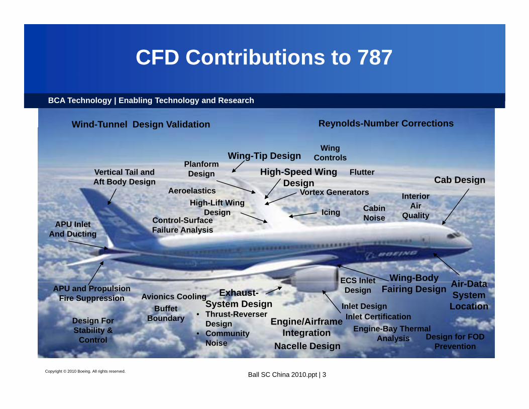
Why is this Important?• Reducing Design Cycle Time while increasing data fidelity
in the early development phases of a new airplane program is critical to competitiveness
• Creating flight predicted S&C and Loads aero data is very time consuming and requires much wind tunnel testing
What are the Technical Challenges?
time consuming and requires much wind tunnel testing.
• Accurate CFD prediction of Loads and S&C characteristics at flight conditions with significant flow separation
Developing Navier Stokes CFD processes for accuracyWhat are we doing?
flight conditions with significant flow separation.• Timely, robust, and repeatable modeling of configurations with
control deflections including spoilers, vortex generators, etc. 787-9 in yaw
• Developing Navier-Stokes CFD processes for accuracy, reliability, and robustness for use by product development engineers for engineering applications.
• Validating/Expanding CFD use in Loads and S&C disciplines
Copyright © 2010 Boeing. All rights reserved. Ball SC China 2010.ppt | 4
p• Integrating wind tunnel and CFD use to reduce cycle
time, cost.787-8 at high Mach with deflected outboard spoilers
CFD at the Edges of the Flight Envelope
BCA Technology | Enabling Technology and Research
What are the Challenges? Cp comparison at approximately 2 5g at Mach diveg
• CFD Issues– Large regions of separated flow– Turbulence models– Need URANS or DES?
approximately 2.5g at Mach dive
• Testing Issues– Close to Mach One– Model aeroelastics– Representative of “Free Air”?
Separated These CFL3D RANS four-engine transport results flowtransport results are typical of CFD issues at the edge of the envelope
Copyright © 2010 Boeing. All rights reserved. Ball SC China 2010.ppt | 5
High-Lift CFD
BCA Technology | Enabling Technology and Research
Why is this Important?Why is this Important?• Optimization of high-lift configurations• Study of simplified/revolutionary high-lift concepts• Study of large number of geometries, device
positions• Understanding of high-lift flow physics• Ability to predict maximum lift• Study of flow-control concepts• Reduction of wind-tunnel tests• Eliminate wind-tunnel effects from test dataEliminate wind tunnel effects from test data• Extend test data to full scale Reynolds numbers
What are the Technical Challenges?• Understanding highly complex flow phenomena• Consistent process for prediction of CLmax• Consistent process for prediction of CLmax• CFD Challenges
– Lack of robustness – Grid resolution requirements are unknown– Turbulence modeling effects are unknown
Copyright © 2010 Boeing. All rights reserved. Ball SC China 2010.ppt | 6
– Unsteady flow analyses are required but unavailable
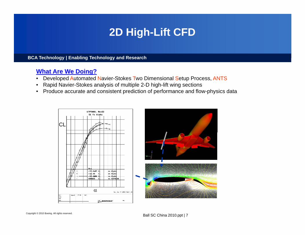
2D High-Lift CFD
BCA Technology | Enabling Technology and Research
What Are We Doing?What Are We Doing?• Developed Automated Navier-Stokes Two Dimensional Setup Process, ANTS• Rapid Navier-Stokes analysis of multiple 2-D high-lift wing sections• Produce accurate and consistent prediction of performance and flow-physics data
CL
α
Copyright © 2010 Boeing. All rights reserved. Ball SC China 2010.ppt | 7
α
3D High-Lift
BCA Technology | Enabling Technology and Research
What Are We Doing?
Pressure coefficients
R l ft
Surface streamlines
• Developed automated Navier-Stokes 3D system analysis process flow with one day turn around
Raw lofts
P iti d t SurfaceVolume
gridPositioned geometry Surface grid
grid
Copyright © 2010 Boeing. All rights reserved. Ball SC China 2010.ppt | 8
CFD in Flutter PredictionsBCA Technology | Enabling Technology and Research
Why is this Important?Why is this Important?• Reduce potential flutter risks in new airplane programs• Enabler to look into non-linear aeroelastic effects earlier in the design cycle• Minimize impact of design modifications necessary to eliminate potential flutter risks• Avoid costly design “fixes” to mature airplane design• Enabler to generate databases for reducing wind-tunnel testing time, cycle time and cost
What are the Technical Challenges?• Highly complex unsteady flow phenomena: coupling of unsteady flow with unsteady
structural dynamics• Existing high speed flutter experimental data are very limited• High speed flutter tests are costly with long design time and limitations due to wind tunnel,
model integrity, subjective engineering calls during tests, etc. • Computational simulations challenges include: long unsteady cycle time, limited validated
methods, mesh deformation robustness for complex geometry, as well as typical steady computational challenges.
Copyright © 2010 Boeing. All rights reserved. Ball SC China 2010.ppt | 9
computational challenges.
CFD in Flutter PredictionsBCA Technology | Enabling Technology and Research
What Are We Doingg• Create, correlate, and validate both steady and unsteady aeroelastic processes. • Assure the processes (TRANAIR-based and CFL3D-based) are robust and repeatable. • Validate process components for each component to assure accurate results: • Initially validate unsteady code for ‘simple’ wing and isolated nacelle oscillations • Apply methodology to compute wind tunnel static aeroelastic deformations and high speed flutter
Wind Tunnel Model
• Apply methodology to compute wind-tunnel static aeroelastic deformations and high speed flutter
Computational Model
Analysis of Flutter Conditions
Copyright © 2010 Boeing. All rights reserved. Ball SC China 2010.ppt | 10
CFD in Flutter PredictionsBCA Technology | Enabling Technology and Research
Unsteady Control Surface Modelingwith CFL3D
Low Subsonic Speed Transonic Speed
Copyright © 2010 Boeing. All rights reserved. Ball SC China 2010.ppt | 11
Stability & Control Application of CFD
BCA Technology | Enabling Technology and Research
Why is this Important?• Aircraft weight/performance impacts• Actuator sizing & system requirements• Improved simulation fidelity
R d d WT t ti• Reduced WT testing
Wh t th T h i l Ch ll ?What are the Technical Challenges?• Highly complex geometries• Increased reliance on augmentation• Multi-functional controls
Hi h fid lit di ti
Lateral/Directional T&I and Wall Interference
• Higher fidelity aero predictions required
• Unsteady flow regimes• Large matrix of data required
A t diti ff t t tSpoiler
Effectiveness M d li
Copyright © 2010 Boeing. All rights reserved. Ball SC China 2010.ppt | 12
• Asymmetry conditions effects on test data and CFD analyses
Modeling
Stability & Control Application of CFD
BCA Technology | Enabling Technology and Research
What Are We Doing R dd Pl f /D t il dWhat Are We Doing• Control surface design
– Sizing trades– Control loads (hinge moments)– Design details
C fi ti t d t di
Rudder Planform/Detailed Design Trades
• Configuration trade studies
• Wind tunnel-to-flight corrections– Tare & Interference– Wall effects
R ld N b ff t– Reynolds Number effects
• Aerodynamic database development– Aeroelastic corrections– Dynamic derivatives
S l t WT– Supplement WT
• Full Spectrum of Codes– A502– Tranair
Copyright © 2010 Boeing. All rights reserved. Ball SC China 2010.ppt | 13
– CFL3D– CFD++ (3D & 2D) Flaperon/Cove
Detail Design
Propulsion Aerodynamics – Thrust Reverser
BCA Technology | Enabling Technology and Research
Stopping Distance Variation w/Runway
Why is this Important?• Thrust Reverser (T/R) provides additional deceleration after
landing. • The T/R is essential to meet landing and take off field length
Condition (Example)
200
300
400
y R
unw
ay
requirements, particularly under icy runway conditions.
What are the Technical Challenges?• Provide required reverse thrust while
0
100
200
icy wet dry
% o
f Dry
• Provide required reverse thrust while considering limits imposed by
– Impingement on A/C surfaces– Re-ingestion by A/C engine– Rudder blanking
Spoilers+Brakes Spoilers+Brakes+Reversers
Delta Lift & Drag Rudder Blanking – Nacelle integration
Copyright © 2010 Boeing. All rights reserved. Ball SC China 2010.ppt | 14
ImpingementRe-ingestion
Propulsion Aerodynamics – Thrust Reverser
BCA Technology | Enabling Technology and Research
What Are We Doing?What Are We Doing?• CFD process developed within Boeing utilized ANSYS/ICEM and CFD++ solver in support of T/R
external efflux pattern development and related analysis of re-ingestion, impingement, and controllability concerns.
Reverser/Airframe CompatibilityReverser/Airframe Compatibility– Installed Analysis
Leading-Edge Integration
Copyright © 2010 Boeing. All rights reserved. Ball SC China 2010.ppt | 15
Nacelle Thermal Analysis
BCA Technology | Enabling Technology and Research
Why is this Important• Minimizes schedule risk• Reduce flight test (cost and schedule savings)Reduce flight test (cost and schedule savings)• Optimize fuel burn (most efficient use of cooling air)• Provide basis for combustor case burnthrough certification
What are the Technical Challenges• Very complex geometry
C l b d diti• Complex boundary conditions• Varying flow regimes (low speed to highly under-expanded jets)
Copyright © 2010 Boeing. All rights reserved. Ball SC China 2010.ppt | 16
Nacelle Thermal Analysis
BCA Technology | Enabling Technology and Research
What Are We Doingg• Engine Bay CFD Analysis (Primarily done by Engine companies)• Coupled fluid/thermal analysis of nacelle structure
•Combustor case burnthrough•Auxiliary exhaust thermal mixingy g
FWDFWD
Copyright © 2010 Boeing. All rights reserved. Ball SC China 2010.ppt | 17
Computational Ice Shape Generation
BCA Technology | Enabling Technology and Research
Why is this Important?• Airframe ice shapes corresponding to critical flight conditions were needed for 787 low
speed wind tunnel testing to measure the impact on aircraft handling characteristics p g p gand maximum lift.
• LEWICE3D, a code developed by NASA, greatly reduced the need to interpolate/extrapolate ice shapes to generate wind tunnel model parts.
• Using LEWICE3D drastically reduced the time needed to generate ice shapes.
What are the Technical Challenges?• LEWICE3D calculates water droplet trajectories through a converged CFD flow-field
to generate a 3D droplet collection efficiency distribution on the airframe This is ato generate a 3D droplet collection efficiency distribution on the airframe. This is a large computation, which had to be parallelized in order to be feasible.
• Finding enough experimental swept wing ice shape data to further refine the ice shape generation model and methodology is problematic.
Copyright © 2010 Boeing. All rights reserved. Ball SC China 2010.ppt | 18
Computational Ice Shape Generation
BCA Technology | Enabling Technology and Research
What Are We Doing?g• Flight conditions considered critical for airframe icing were selected.• Navier-Stokes solvers CFD++ or OVERFLOW were run with these conditions to
generate a flow-field for input into LEWICE3D.• LEWICE3D generated a collection efficiency and ice shape cuts.• Ice shape cuts were used to produce lofts for stereo lithography production into• Ice shape cuts were used to produce lofts for stereo lithography production into
wind tunnel model parts.
Copyright © 2010 Boeing. All rights reserved. Ball SC China 2010.ppt | 19
Water Droplet Collection Efficiency Ice Shape Cuts on Wing Leading Edge
Closing Thoughts
BCA Technology | Enabling Technology and Research
• CFD exists to enable new solutions to problems, reduce airplane development cost, and reduce time to market
• CFD can allow you to safely explore areas of the flight regime without putting a pilot at risk
• CFD can allow you to analyze conditions for which physical simulation is either very expensive or not possible, such as h i l i t d f ll fli ht R ld bhypersonic propulsion systems and full flight Reynolds number testing
• Accuracy, robustness and timeliness are the keys to acceptance and use in an industrial environmentuse in an industrial environment
• Impediments: applications that do not scale well (to 1000’s of processors) – this is science, resources to run 1000s of flight conditions on 100’s of processors – this is engineering & business
Copyright © 2010 Boeing. All rights reserved. Ball SC China 2010.ppt | 20
conditions on 100 s of processors this is engineering & business