Recent Developments at the Brookhaven Source Development Laboratory Brian Sheehy National Synchrotron Light Source Brookhaven National Laboratory Beam Physics Seminar Jefferson Laboratory October 15, 2004
Transcript
Recent Developments at the Brookhaven Source Development Laboratory
Brian SheehyNational Synchrotron Light SourceBrookhaven National Laboratory
Beam Physics SeminarJefferson Laboratory
October 15, 2004
The SDL TeamG. L. Carr, E. D. Johnson, S. Krinsky, H. Loos , J. B. Murphy, J. Rose, T. Shaftan, B.
Sheehy, Y. Shen, X.-J. Wang, Z. Wu, L. H. YuNational Synchrotron Light Source; Brookhaven National Laboratory
• Facility Overview
•Diagnostics/Control
• High Gain Harmonic Generation (HGHG)• Cascading• Tunability
•Optical Compression and and Shaping coherent FEL output• SPIDER and CPA
•Other Sources• MV/cm peak field THz source
Facility Overview
AdjustableChicane
177MeV
RF zeroPhasingPhotoinjectorCTR Monitor
Normal incidence
77 MeV
FEL seedat 800 nm
Modulator Undulator
NISUS pop-inmonitors
FEL MeasurementEnergy, Spectrum, Synchronizationand Pulse Length Measurementsat 266 nm
s
Ion Pair ImagingExperimentat 88 nm
Nisus Wiggler
30 mJ Ti:SapphireAmplifier
DispersionMagnet Trim Chicane
• BNL Gun IV photoinjector, S-band, 4.5 MeV• 4 stage Linac up to 200 MeV
• upgrade to 250-300 MeV near completion• Magnetic Chicane Compressor R56 = 5 cm• Seed at λs= 800 nm in 1 m undulator K=1.67 , followed by dispersive section• NISUS undulator, 10 m, 256 period, K = 1.1
• fundamental at λs /3 = 266 nm, output 100 µJ• 1 µJ at third harmonic λs /9 = 89 nm
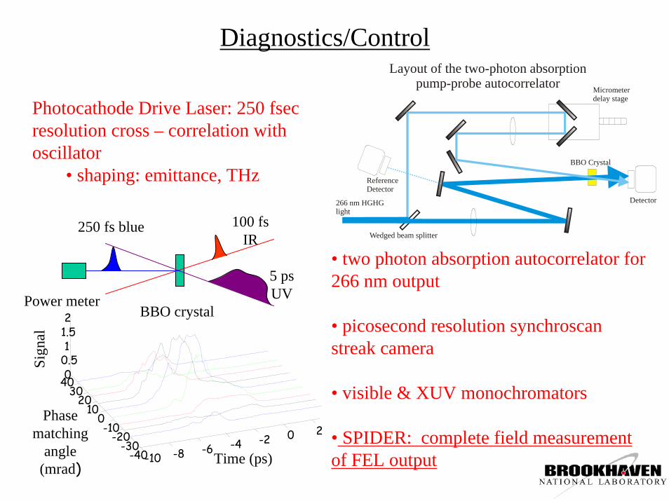
• two photon absorption autocorrelator for 266 nm output
• picosecond resolution synchroscanstreak camera
• visible & XUV monochromators
• SPIDER: complete field measurement of FEL output
RF Zero PhaseRF Zero Phase
100 150 200 250 300
406080
100120140
100 150 200 250 300 350
406080
100120140160180
50 100 150 200 250 300 350 400
20406080
100120140160180200
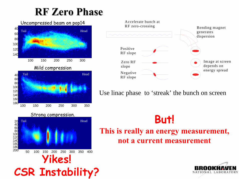
Uncompressed beam on pop14
Mild compression
Strong compression.
HeadTail
HeadTail
HeadTail
Positive RF slope
Accelerate bunch at RF zero-crossing
Image at screen depends on energy spread
Bending magnet generates dispersion
Zero RF slope
Negative RF slope
Yikes!CSR Instability?
Use linac phase to ‘streak’ the bunch on screen
But!This is really an energy measurement,
not a current measurement
Longitudinal phase space tomography (H. Loos)
-400 0 400
-400 0 400
-400 0 400
-400 0 400
-400 0 400
-400 0 400
-400 0 400
-400 0 400
-400 0 400
-400 0 400
-400 0 400
-400 0 400
-400 0 400
-400 0 400
-400 0 400
-400 0 400
Spread (keV)
-4 -2 0 2 4
-20
-10
0
10
20
Time (ps)
Ener
gy (
keV
)
-6 -4 -2 0 2 4 6-10
0
10
∆E
(ke
V)
-6 -4 -2 0 2 4 60
25
50
Cur
rent
(A
)
-6 -4 -2 0 2 4 60
0.1
0.2
0.3
Time (ps)
Inte
nsity
t
EDrive laser
current
E-t corrEach value of the chirp manifests a different projection of the phase space.
The energy projection can be very deceptive
Huang & Shaftan NIMA 528, 345 (2004)Current and energy profiles of a chirped beam (a) without energy modulation, (b) with energy modulation.
• Degree of modulation observed inconsistent with CSR models• S. Heifets, G. Stupakov and S. Krinsky PRST-AB 5, 064401 (2002)• Z. Huang & H.-J.Kim PRST-AB 5, 074401 (2002)• Z. Huang T. Shaftan SLAC-PUB-9788, 329.
• Longitudinal Space Charge model: • small modulation in photocathode drive laser • small current modulations due to drive laser modulations at photocathode• longitudinal space charge forces result in enhanced energy modulations in the bunch• these dominate the horizontal distribution in zero-phase measurements• experimental confirmation
• lack of coherent enhancement of the IR in coherent transition radiation• modulation behavior with chicane strength, trans beam size, energy, etc• phase space tomography
potential threat for short pulse short wavelength FEL’s• can convert to current modulation; larger energy spresd • goes away for perfectly uniform laser temporal profile
Theory: Huang & Shaftan NIM A 528, 345 (2004)Experiment: Shaftan et al NIM A 528, 397 (2004)
Ti:Sapph Oscillator
Dazzler
Stretcher
Amplifier
Compressor
ω−tripler
800 nm9 nJ100 fsec
5 nJ200-400 psec
25 mJ170-350 psec
15 mJ0.1 - 30 psec
266 nm1.8 mJ
Time (psec)
Inte
nsity
(arb
uni
ts)
Temporal Shaping (in progress)At SDL in collaboration with SPARC
and SLAC
Amplified and compressed IR pulse
Millennia Laser
Tsunami Laser
Spec
trum
Ana
lyze
r
Aut
o-co
rrel
ator
OpticalIsolator
StretcherCompressor 1
Regenerative Amplifier
2-pass Amplifier
2-pass Amplifier
VariablePowerDivider
Phot
ocat
hode
GC
R-1
70 Y
AG
Las
er
GC
R-1
50 Y
AG
Las
er
Photodiode
Pow
erA
tten
ω+
ω
= 2ω
ω+
2ω
= 3ω
Autocor-rellator
SpotImaging
Power Mon
Optical Relay, 14 meters
Monument
PowerAtten
SpatialFilter
Compressor 2
Optical Relay, ~35 metersSeedingAnd Diagnostics
Daz
zler
ZnTeAccelerator
TrimModulator
Dipole
Monitor
Polarizer
Analyzer
λ/4 Plate
toNISUS
Spectro-meterFiber
Trim
Seed LaserDelay
ElectronsLaser
(800 nm)
Electro-Optic e-beam meaurements
( ) λε
πϕ+
=∆1
2 vac4130 lErn
Retardation induced by e-bunch field Evac
RTRT
+−
=∆ )sin( ϕ
Asymmetry in transmitted/reflected gives ∆ϕ
Chirp seed and spectrally resolve the asymmetry –single shot measurement (800 fsec resolution).
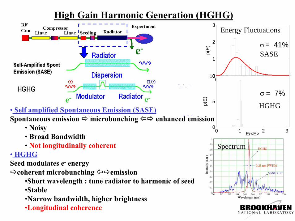
• Noisy• Broad Bandwidth• Not longitudinally coherent
• HGHG Seed modulates e- energy
coherent microbunching emission•Short wavelength : tune radiator to harmonic of seed•Stable•Narrow bandwidth, higher brightness•Longitudinal coherence
Spectrum
0 1 2 30
1
2
3
p(E
) σ= 41%
E/<E>0 1 2 30
5
10
p(E
) σ = 7%
Energy Fluctuations
SASE
HGHG
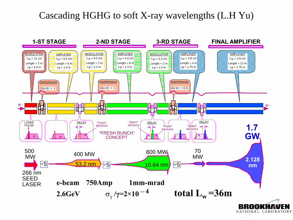
Cascading HGHG to soft X-ray wavelengths (L.H Yu)
1-ST STAGE 2-ND STAGE 3-RD STAGE FINAL AMPLIFIER
AMPLIFIER λw = 6.5 cm
Length = 6 m Lg = 1.3 m
AMPLIFIER λw = 4.2 cm
Length = 8 m Lg = 1.4 m
AMPLIFIER λw = 2.8 cm
Length = 4 m Lg = 1.75 m
MODULATOR λw = 11 cm
Length = 2 m Lg = 1.6 m
MODULATOR λw = 6.5 cm
Length = 2 m Lg = 1.3 m
MODULATOR λw = 4.2 cm
Length = 2 m Lg = 1.4 m
DISPERSION
dψ/dγ = 1
DISPERSION
dψ/dγ = 1
DISPERSION
dψ/dγ = 0.5
DELAY DELAY DELAY“Spent” electrons “Fresh”
electrons“Spent”
electrons“FRESH BUNCH”
CONCEPT
“Fresh” electrons
e- e-
266 nm SEED LASER
53.2 nm2.128nm10.64 nm÷5 ÷5 ÷5
400 MW 800 MW 70 MW
1.7 GW
500 MW
e- e-
LASER PULSE
AMPLIFIER λw = 2.8 cm
Length = 12 m Lg = 1.75 m
e-beam 750Amp 1mm-mrad2.6GeV σγ /γ=2×10 – 4 total Lw =36m
A proposed 2 stage cascade for the SDL
e-beam600Amp250 MeV2.7 mm-mradσγ / γ = 1.×10 - 4
Pin=1.5 MW266nm 66.5 nm
Pout=140 MW56 MW133nm
2m VISA
6 m NISUS0.8m MINI
Pulse length ~ 0.5ps 70µJ
A Novel Tunability scheme for HGHG (T. Shaftan)
Radiator DS Modulator
1 0 1174.5
175
175.5.
1 0 1174.5
175
175.5.
1 0 1174.5
175
175.5.
.
Seed with fixed λ
before FELafter Modulatorafter DS
E [MeV] E [MeV] E [MeV]
t [ps]
• Dispersive Section (DS) converts energy modulation into bunching• DS also compresses the energy modulation wavelength• a small but measureable effect in our machine, but could be optimized to yield a tuning range of 20%
(Dispersive Section)
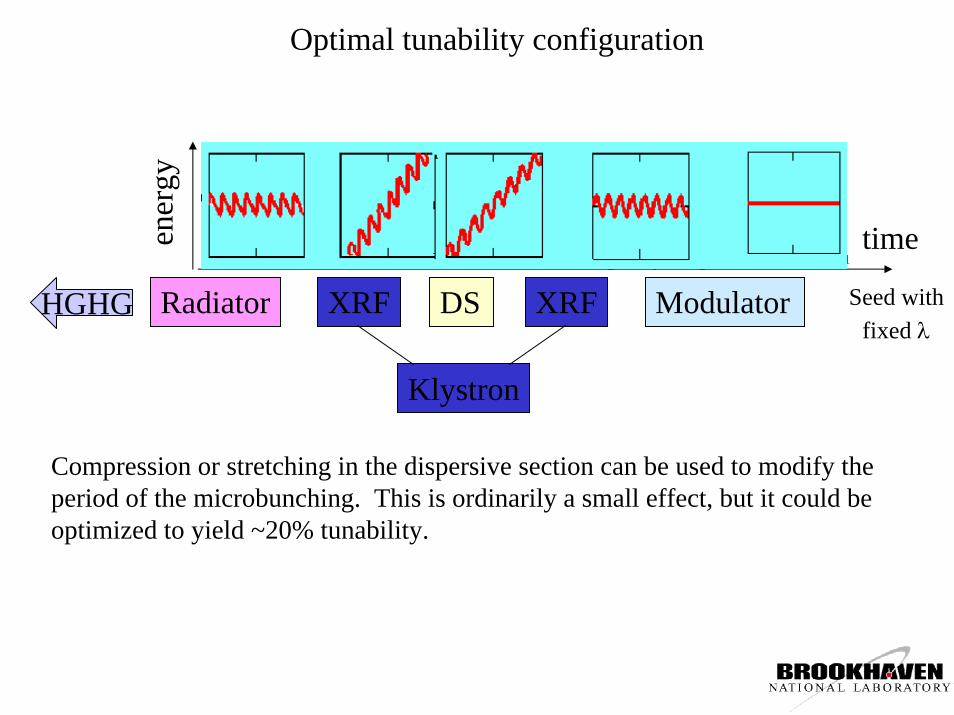
Optimal tunability configuration
Klystron
Radiator DS ModulatorXRF XRF1 0 11
0
1
.
1 0 11
0
1
.1 0 11
0
1
.1 0 11
0
1
.1 0 11
0
1
. time
HGHG Seed with fixed λ
ener
gy
Compression or stretching in the dispersive section can be used to modify the period of the microbunching. This is ordinarily a small effect, but it could be optimized to yield ~20% tunability.
SDL Experiment
• Chirp is provided by shifting beam off-crest in tank 4 (Emax = 58 MeV)
• Tank 4 phase shift: from +25° to -45°• DS is set to maximum current (200 A)• Nothing else was changed !• Spectrum of HGHG is measured
for different amounts of chirp
Gun 4.5 MeV
Tank 1Tank 2Tank 3Tank 435 MeV72 MeV130 MeV190 MeV
ModDSNISUS266 nm 0.8 um
.Tank 4 phase
Tank 4energygain
seed
HGHG output spectra for various tank 4 phases:
-45° -30°-10°
0°+10°
+25°
Wavelength, nm
HG
HG
inte
nsity
, a.u
.
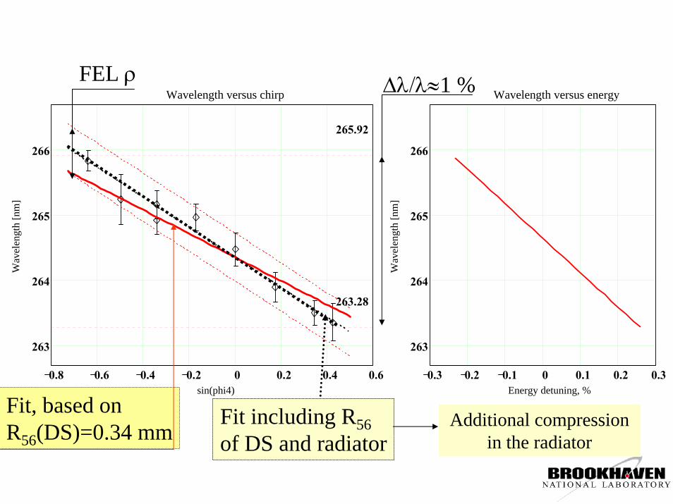
Fit, based on R56(DS)=0.34 mm
0.8 0.6 0.4 0.2 0 0.2 0.4 0.6
263
264
265
266
Wavelength versus chirp
sin(phi4)
Wav
elen
gth
[nm
]
263.28
265.92
0.3 0.2 0.1 0 0.1 0.2 0.3
263
264
265
266
Wavelength versus energy
Energy detuning, %W
avel
engt
h [n
m]
∆λ/λ≈1 %FEL ρ
Fit including R56of DS and radiator
Additional compressionin the radiator
Spectral Phase Measurements; chirping and shaping FEL output
• Optical Compression and and Shaping coherent FEL output
• Measuring Spectral Phase• SPIDER technique• Application at 266nm for picosecond laser pulses
• Measurements HGHG• Unchirped, narrow bandwidth
•Near transform limit• Chirping and Compressing
High Gain Harmonic Generation (HGHG)and Chirped Pulse Amplification (CPA)
time
freq
uenc
y
time
e-en
ergy time
freq
uenc
y
ω
e- e-
Opticalcompressor
time
freq
uenc
y
Tb
T<<Tb
• Match optical seed chirp to electron energy chirp•Resonant frequency in modulator matches seed at each moment in the bunch
• Output pulse is also chirped• Longitudinal coherence permits optical compression to transform limit
• femtosecond pulses • Sensitive to spectral phase distortion• Li Hua Yu et al Phys Rev E 49, 4480 (1994)
Shaping HGHG
• Coherent control at short wavelengths• For both chirping and shaping, the question is:How will phase modulation in the seed transfer to HGHG?
•Can distortions be used as a probe of e- beam and radiator dynamics
Potential Problems / Interesting Questions• synchronization jitter • stability• noise & harmonics• optical field is bipolar, electron density is not.
(Walmsley group, Oxford)
266 nm
400 nm800 nm
Measuring the spectral phase: SPIDER(Spectral Interferometry for Direct Electric-Field Reconstruction)
ωc
D(ω
c) 2π/τ
C. Iaconis and I. A.Walmsley, Opt. Lett. 23, 792–794 (1998).
DOWNCONVERSION SPIDER LAYOUT
Spectrometer
800 nm(seed)
+266 nm
(HGHG)
Michelsoninterferometer
BBO
.
266
nm
800 nm
Filter
Compressor used as stretcher
DelayLine
400 nm
• Separate seed pulse (800 nm) and HGHG• stretch seed to 60 psec• make 2 HGHG pulse replicas in interferometer and separate by τ=3.5 psec• Downconvert to 400 nm in BBO• frequency shift is Ω=0.2 THz
• set spectrometer to λc=800 nm• measure 400 nm SPIDER trace in 2nd order• block seed, remove filter and measure 266 nm calibration trace in 3rd order
ang
Spidering a laboratory 266 nm source
-0.05 0 0.05-10
0
10
20
30
ω - ω0 (PHz)
radi
ans
amplitudephasefit chirpphase-chirp
-0.05 0 0.050
0.2
0.4
0.6
0.8
1
ω - ω0 (PHz)
inte
nsity
(arb
uni
ts)
Typical Spider Trace
Reconstructed phase and amplitude Comparison with x-correlation
• stretch a 100 femtosecond 800 nm Ti:Sapph chirped-pulse-amplification system• Frequency-triple in BBO to 266 nm(spoil phase matching to create an asymmetry in the time profile)• Compare scanning multishot cross-correlation of the 266 nm and a short 800 nm pulse with the average reconstruction, convolved with 250 fsec resolution of the x-correlator
-1 -0.5 0 0.5 1 1.50
0.2
0.4
0.6
0.8
1
time (psec)
inte
nsity
(arb
uni
ts)
spidercross correlation
900 fsec FWHM
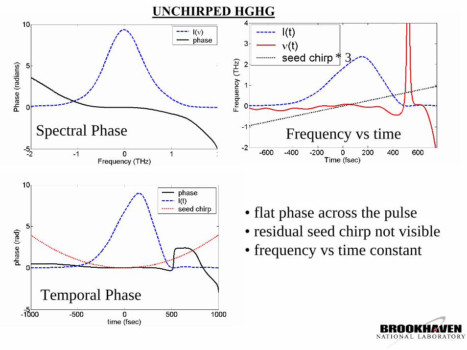
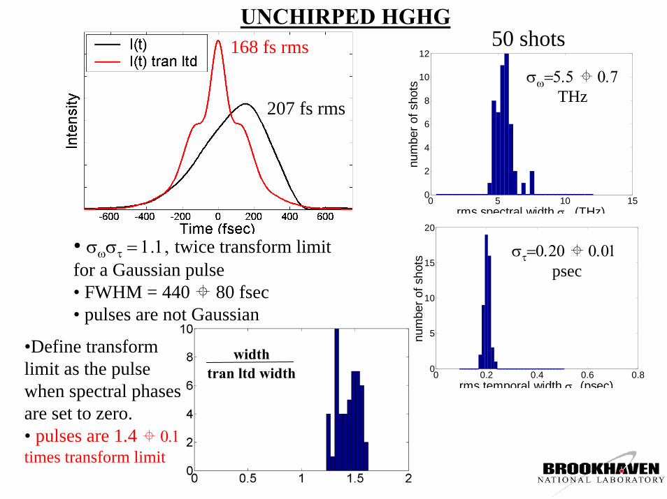
UNCHIRPED HGHG
time
freq
uenc
y
time
e-en
ergy time
freq
uenc
y
Tb
ω
e- e-
• Stretch seed to 6 psec• optimize compression / minimize e- energy chirp• minimize output bandwidth
Frequency vs time
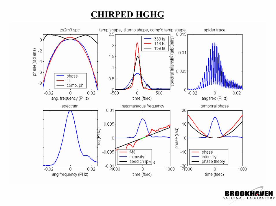
UNCHIRPED HGHG
* 3
Spectral Phase
• flat phase across the pulse• residual seed chirp not visible• frequency vs time constant
Temporal Phase
50 shots
0 5 10 150
2
4
6
8
10
12
rms spectral width σ (THz)
num
ber o
f sho
ts
0 0.2 0.4 0.6 0.80
5
10
15
20
rms temporal width σ (psec)
num
ber o
f sho
ts
σω=5.5 0.7THz
στ=0.20 0.01psec
•Define transform limit as the pulse when spectral phases are set to zero.• pulses are 1.4 0.1 times transform limit
widthtran ltd width
• σωστ = 1.1, twice transform limit for a Gaussian pulse• FWHM = 440 80 fsec• pulses are not Gaussian
•The seed chirp is clearly observed in the HGHG output over part of the pulse• distortion in the pulse wings deteriorates compressibility
Matching Electron and Optical Chirp
λ
t
γ
Optical BeamElectron Beam
•Electron beam has curvature due to sinusoidal acclerating field•If chirp is not matched, resonance occurs only over a short portion of the electron bunch – correlation between compressibility and uncompressed pulse length?•Mismatched is more sensitive to synchronization jitter.
Uncompressed rms pulse width (fsec)
Com
pres
sion
Fac
tor
correlation between compressibility and uncompressed pulse length
Compression factor
rms width‘compressed’ width
‘compressed width/transform limit
• most pulses compressible in principle to ~ twice transform limit•quadratic spectral phase (defines compressor) not determined only by chirp• a ‘reasonable’ fixed compressor compresses only 15% of pulses
Fit b for each shot and ‘compress’:
CPA Summary• Successfully demonstrated SPIDER at shortest wavelength and longest pulse lengths reported.
• Characterized spectral phase of High Gain Harmonic Generation
• near transform limited
• Chirped Pulse Amplification• Imparted positive chirp commensurate with seed chirp• poorly matched electron chirp• sensitivity to other factors still unclear
• shown the viability of CPA and potential for more complex pulse shaping
GaAs
Typical Laser-based THz Source
UF laserTHz
• Transient current is subpicosecond, Ea ~ 10 kV/cm• Relaxation is slow: half-cycle pulse• THz yields: 1 nJ (250 kHz) to 1 uJ (1 kHz), • size scaling limit 1 - 10 uJ• optical rectification yields are similar w/ higher freqs.
photocathodeelectron gun
dipole chicanecompressor~ 300 fs, 700pC electron bunches
• bunch length ~ λ, coherent enhancement• energy of 80 uJ measured in this setup ( E ~ 1 MV/cm)
• 2 orders of magnitude larger than other sources • Scales as Ne-
2
• spectral content to 2 THz• higher for shorter bunches
• This machine is not optimized for THz production 0 2
Inte
nsity
Frequency (THz)
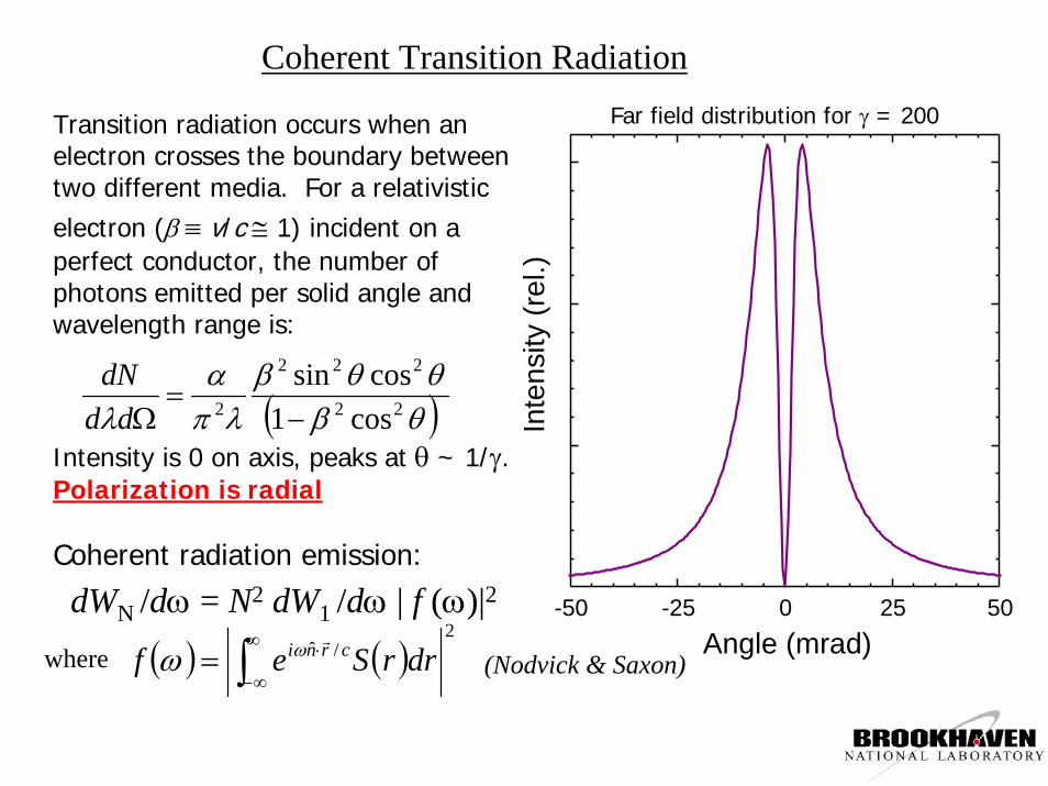
Coherent Transition Radiation
Transition radiation occurs when an electron crosses the boundary between two different media. For a relativistic electron (β ≡ v/c ≅ 1) incident on a perfect conductor, the number of photons emitted per solid angle and wavelength range is:
( )θβθθβ
λπα
λ 22
222
2 cos1cossin
−=
ΩdddN
Intensity is 0 on axis, peaks at θ ~ 1/γ.Polarization is radial
Coherent radiation emission:
-50 -25 0 25 50
Inte
nsity
(rel
.)
Angle (mrad)
Far field distribution for γ = 200
dWN /dω = N2 dW1 /dω | f (ω)|2
( ) ( )2
/ˆ∫∞
∞−
⋅= drrSef crniωωwhere (Nodvick & Saxon)
Electro-Optic measurement of THz field
•Polarization of synchronized optical field is retarded by instantaneous THz field in the ZnTe crystal by Pockels effect• analyzer gives time resolved 2-dimensional distribution of electric field component
CCDZnTe AnalyzerPolarizer
Lens
Electron Beam
Vacuum Window
Paraboloid
Coupling Hole, 2 mmTi:Sa Laser
Delay
λ/4
EO Detection method:T.F. Heinz/Columbia & X.-C. Zhang/Rensselaer Accelerators:Yan, Van der Meer et al PRL 2000Wilke et al PRL 2002Loos et al PAC 2003Chirped sampling:Jiang and Zhang, APL (1998)
Pixels
Pix
els
100 200 300 400 500 600
100
200
300
400
Horizontal (mm)
Verti
cal
(mm
)
-2 -1 0 1 2
-2
-1
0
1
2
Image Processing for electric field recovery
Use compensator waveplate to detect sign of polarization change.Reference IR (left) and Signal IS (right) obtained simultaneously.Rescale and normalize both.Calculate asymmetry A of Signal.Subtract asymmetry pattern w/o THz.
A = 2IS/IR - 1
Coherent THz Transition Radiation Pulses from the SDL Linac
0.0 0.5 1.00
20
40
60
80
Pyr
oele
ctric
Det
ecto
r Res
pons
e [µ
J]
Time [ms]
Up to 80 µJ (!) per pulse -> consistent with calculation
0 20 40 600
2
4
6
8
10
Inte
nsity
[arb
.]
Frequency [cm-1]
0 1 2 Frequency [THz]
Intensity to 2 THz (higher with shorter bunches)
photocathodeelectron gun
dipole chicanecompressor~ 300 fs, 700pC electron bunches
Decompose electron beam coulomb field in Gauss-Laguerre modes.
Calculate complex transmission factors through experiment for THz spectral range.
Use bunch form factor to reconstruct time dependence.
20 ps
Cross section of E-field at focus as a function of time
E-field along horizontal plane
Note: opposite sides are asymmetric, as shown (radial polarization)
Measurement
Calculation (mm)
Temporal-spatial E-field profile of coherent transition radiation pulse at ~ f/1.5 focus
Opportunities in Magnetism for THz pulses(Epeak = 1 MV/cm → Bpeak = 3 kilogauss)
magneticviscosity
field(gauss)
Ultra-Short Pulses and/or High Fields -- D. Arena / NSLSCurrent state of the art for “ultra-fast” dynamics experiments:
10
-15
10
-12
10
-9
10
-6
Excitation / Interaction
exchange interaction
Stoner excitations
spin waves
(low q limit)
spin-lattice relaxation
in manganites
precessional rotation
and damping
spin coherence
and spin diffusion
Coercivity / Saturation
time(sec)
10
5
10
4
10
1
10
2
10
3
soft
manganites
permallo
y
transit
ion
metals & allo
ysa″
Fe 16N 2
dilute
magnetic se
micond.
rare-earth
magnets
Role forTHz!
Time: ~100 fs (lasers)~100 ps (synchrotron)
Field: ~10 – 100 gauss (stripline)
Soft Modes in Ferroelectrics & Perovskites (PbTiO3)G. L. Carr
Use half-cycle pulse to coherently drive atoms, probe motion as a function of time (needs diffraction probe).
THz
HCP
ETH
z HC
P
ETH
z HC
P
E
E(t)
Observe “shift” in diffraction spot(s)
DOE Workshop on Ultrafast X-rays
Why Make Terahertz Pulses ?
• Imaging/Remote Ranging– non-ionizing
– medical– safely use to monitor public or battlefield environments
– CHEMICALLY AND BIOLOGICALLY SENSITIVE– explosives, weapons detection– phonon modes in DNA (Woolard et al Phys Rev E 65, 051903)
– remote ranging with bacterial species identification – a lot of work remains in sources, detection, and characterization.
explosives
weaponsWoolard et al THz Differential Absorption Radarmodel (Bio early warning)
1 km
Some More Reasons•Ultra-fast dynamics (< 1 ps time scale)
– directly measure complex dielectric response of sample – strong coupling of optical/THz excitations in correlated e- systems (e.g. high-Tc superconductors)
•Low frequency, non-linear properties of materials– nanoparticles / quantum dot arrays in dielectrics
– Optronics: Ultrafast components in all-optical circuits– faster, EMP resistant
•Orienting Molecules– spectroscopy and chemistry from coherent rovibrational states– manipulate internal molecular fields / fundamental measurements & coherent control
•Structural transitions–Large E-field to coherently “shove” atoms
THz Summary
• The DUVFEL THz source pulse energy exceeds other sources by 2 orders of magnitude (DUVFEL 80 uJ, Laser sources 1 uJ, JLab ERL 0.5 uJ)
• fundamental dynamics ( magnetic systems, strongly correlated e- systems, nanoparticles…) • large area imaging• single shot detection• explore nonlinear effects• THz as pump in pump-probe experiments
•MV/cm E-fields and kilogauss B-fields •THz pulse shaping (through e-beam and optically)
• Accelerator sources have not been optimized for THz production
Global Summary
SDL continues to be an important test bed for FEL science and technology development, as well as a user facility
•answers to important questions of beam dynamics for next generation sources
HGHG is an extremely promising candidate for producing longitudinally coherent short wavelength ultrafast pulses
•tunability•chirped pulse amplification and Shaping•cascading is in the works
The THz production is a truly unique source capable of opening a new regime of dynamics to study