Slide: 1 Recent Developments in Electric Power Recent Developments in Electric Power Transmission Technology Transmission Technology Dr. Dr. Kalyan Kalyan Sen Sen April 15, 2003 April 15, 2003
Transcript
Slide: 1
Recent Developments in Electric PowerRecent Developments in Electric PowerTransmission TechnologyTransmission Technology
Dr.Dr. Kalyan Kalyan Sen Sen
April 15, 2003April 15, 2003
Slide: 2
S o u rc e L o a d
L o a d
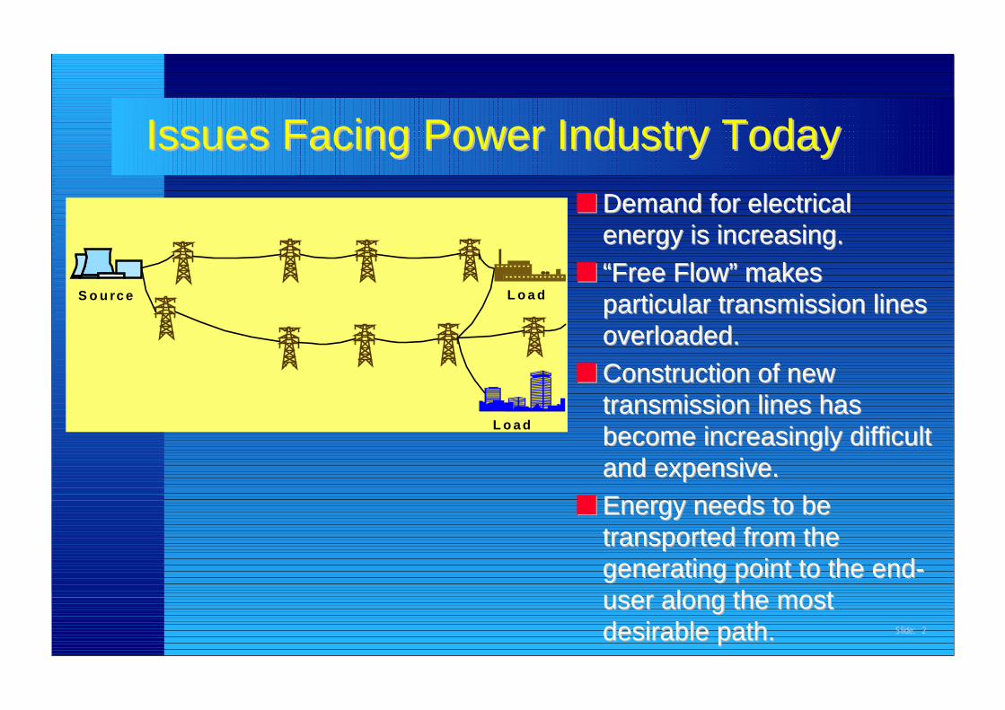
■■ Demand for electricalDemand for electricalenergy is increasing.energy is increasing.
■■ Construction of newConstruction of newtransmission lines hastransmission lines hasbecome increasingly difficultbecome increasingly difficultand expensive.and expensive.
■■ Energy needs to beEnergy needs to betransported from thetransported from thegenerating point to the end-generating point to the end-user along the mostuser along the mostdesirable path.desirable path.
Issues Facing Power Industry TodayIssues Facing Power Industry Today
Slide: 3
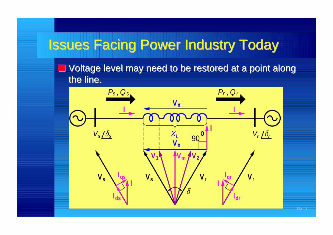
Issues Facing Power Industry TodayIssues Facing Power Industry Today■■ Voltage level may need to be restored at a point alongVoltage level may need to be restored at a point along
the line.the line.
V
IIds
s
sV
Vs δ
sVIqs
P ,s Qs
I
II
δdr
I90
2m1
VX
XL
V V
Vr Iqr
οοοο
VX
rP , Qr
I
Vr
V rr δ
Slide: 4
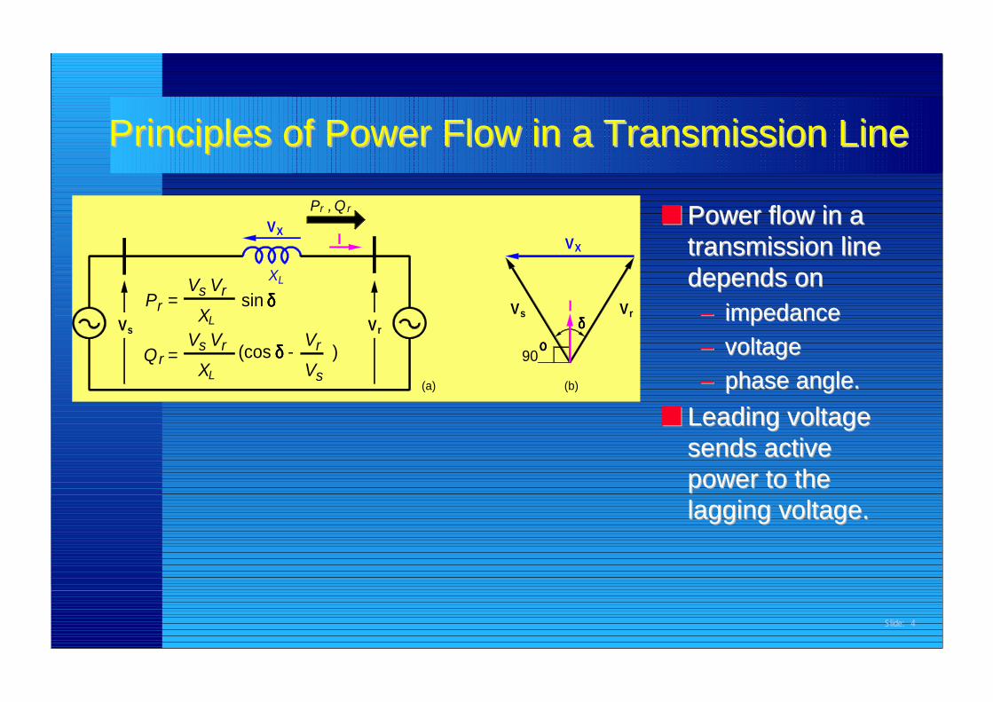
■■ Power flow in aPower flow in atransmission linetransmission linedepends ondepends on–– impedanceimpedance–– voltagevoltage–– phase angle.phase angle.
■■ Leading voltageLeading voltagesends activesends activepower to thepower to thelagging voltage.lagging voltage.
Principles of Power Flow in a Transmission LinePrinciples of Power Flow in a Transmission Line
XQr V
r
s
V
L
XV
sr
ss V
=
=PV
X
- )
r
r
L
V (cos δδδδ
Vsin δδδδ
XL
Vr
VI
QrP , r
(a) (b)
δδδδVs
90οοοο
VX
VI r
Slide: 5
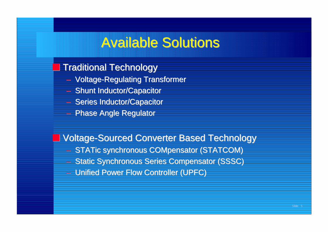
Available SolutionsAvailable Solutions■■ Traditional TechnologyTraditional Technology
■■ Voltage-Voltage-SourcedSourced Converter Based Technology Converter Based Technology–– STATic synchronous COMpensator (STATCOM)STATic synchronous COMpensator (STATCOM)–– Static Synchronous Series Compensator (SSSC)Static Synchronous Series Compensator (SSSC)–– Unified Power Flow Controller (UPFC)Unified Power Flow Controller (UPFC)
Slide: 6
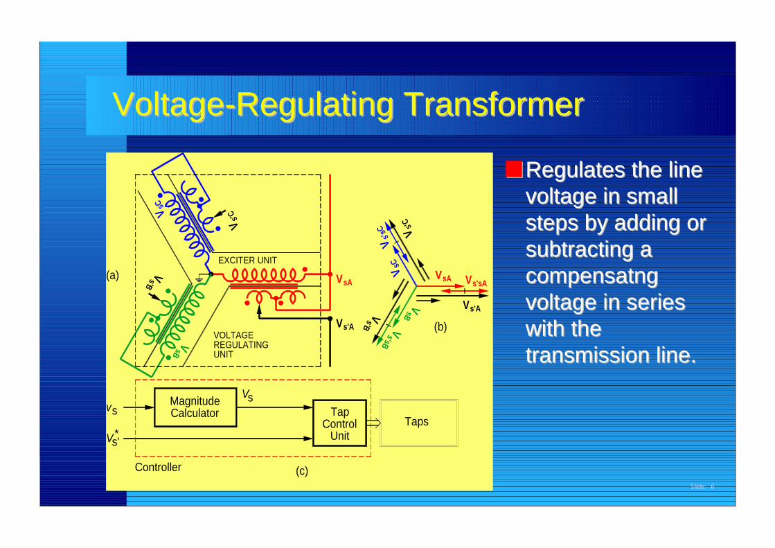
■■ Regulates the lineRegulates the linevoltage in smallvoltage in smallsteps by adding orsteps by adding orsubtracting asubtracting acompensatngcompensatngvoltage in seriesvoltage in serieswith thewith thetransmission line.transmission line.
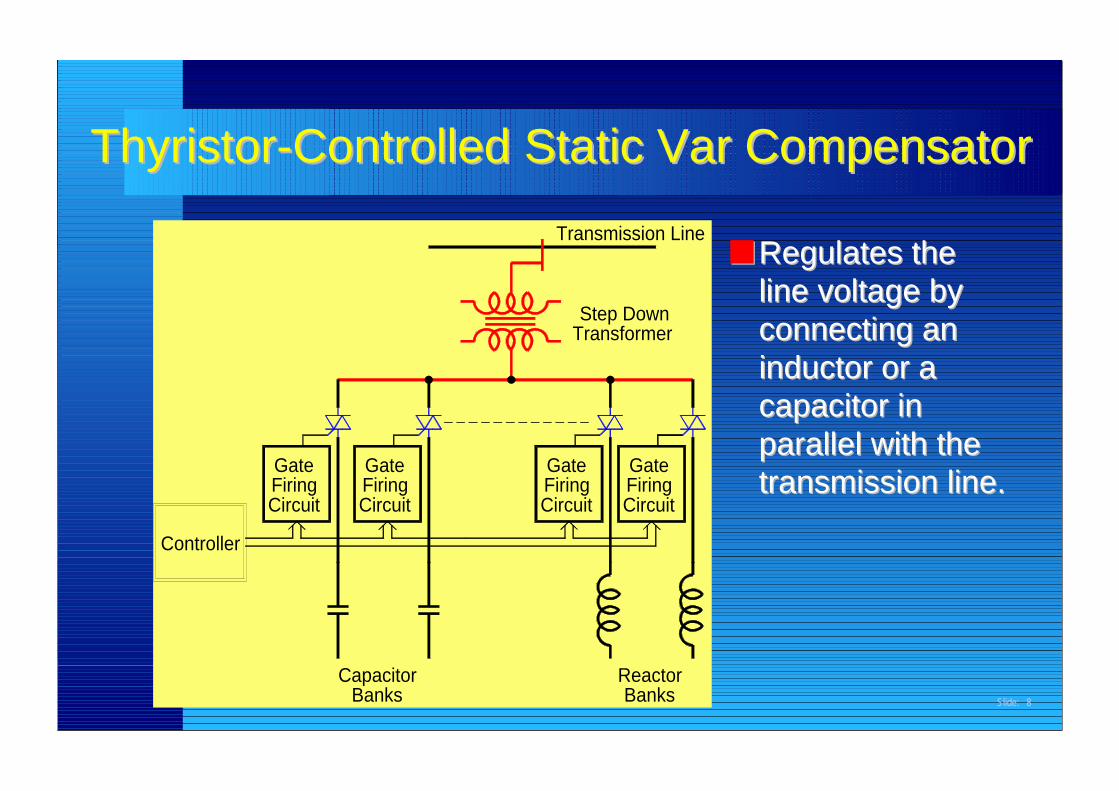
■■ Regulates theRegulates theline voltage byline voltage byconnecting anconnecting aninductor or ainductor or acapacitor incapacitor inparallel with theparallel with thetransmission line.transmission line.
ThyristorThyristor-Controlled Static -Controlled Static Var CompensatorVar Compensator
Controller
CapacitorBanks
GateFiringCircuit
GateFiringCircuit
ReactorBanks
GateFiringCircuit
GateFiringCircuit
Step DownTransformer
Transmission Line
Slide: 9
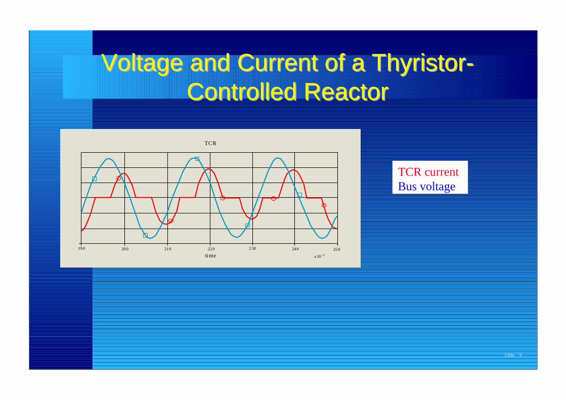
Voltage and Current of a Voltage and Current of a ThyristorThyristor--Controlled ReactorControlled Reactor
TCR currentBus voltage
TCR
19 0 20 0 21 0 22 0 2 30 24 0
time25 0
x 10 -3
Slide: 10
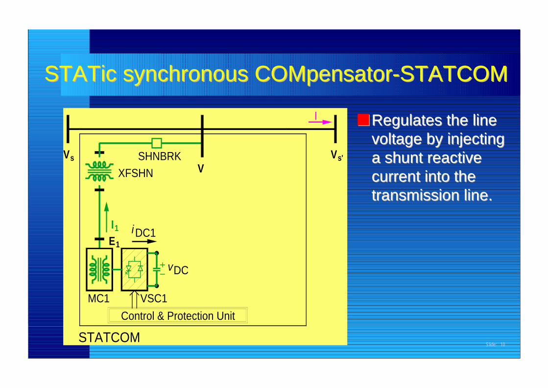
■■ Regulates the lineRegulates the linevoltage by injectingvoltage by injectinga shunt reactivea shunt reactivecurrent into thecurrent into thetransmission line.transmission line.
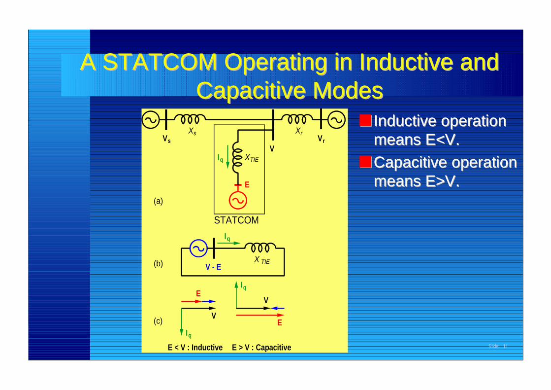
A STATCOM Operating in Inductive andA STATCOM Operating in Inductive andCapacitiveCapacitive Modes Modes
E > V : Capacitive
STATCOM
E < V : Inductiveq
(c)I
(b)
IE
q
VE
V
V - E
Iq
TIEX
Xs
(a)
V
Iq
E
VXTIE
sr
Xr V
Slide: 12
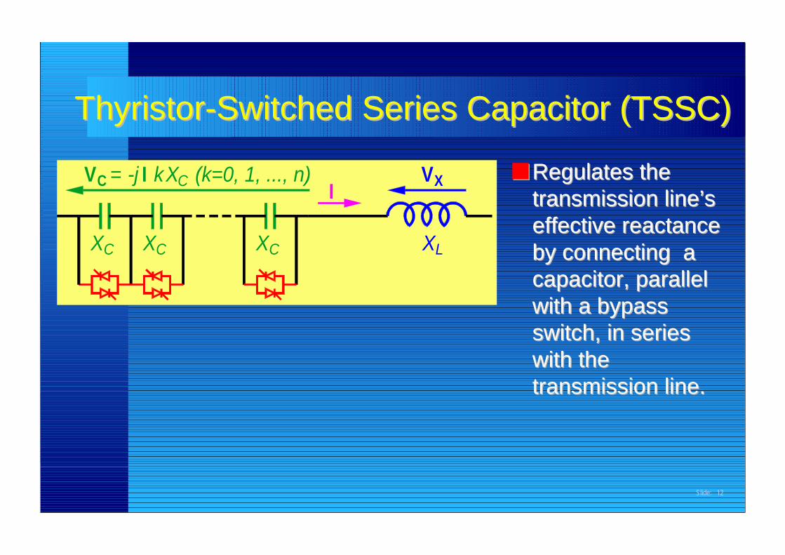
■■ Regulates theRegulates thetransmission line’stransmission line’seffective reactanceeffective reactanceby connecting aby connecting acapacitor, parallelcapacitor, parallelwith a bypasswith a bypassswitch, in seriesswitch, in serieswith thewith thetransmission line.transmission line.
Thyristor-Switched Series Capacitor (TSSC)Thyristor-Switched Series Capacitor (TSSC)
V =C k C
X CXC CX
X (k=0, 1, ..., n)-j II X
LX
V
Slide: 13
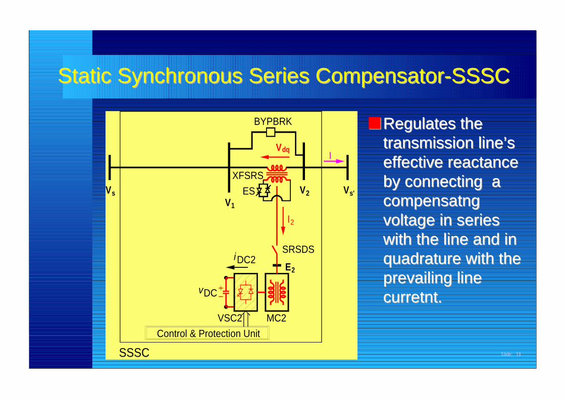
■■ Regulates theRegulates thetransmission line’stransmission line’seffective reactanceeffective reactanceby connecting aby connecting acompensatngcompensatngvoltage in seriesvoltage in serieswith the line and inwith the line and inquadrature with thequadrature with theprevailing lineprevailing linecurretnt.curretnt.
Static Synchronous Series Static Synchronous Series CompensatorCompensator-SSSC-SSSC
VSC2Control & Protection Unit
SSSC
vDC
Vs
I2
MC2
iDC2 E2
SRSDS
V
1VES
XFSRSV2
dqI
BYPBRK
Vs'
Slide: 14
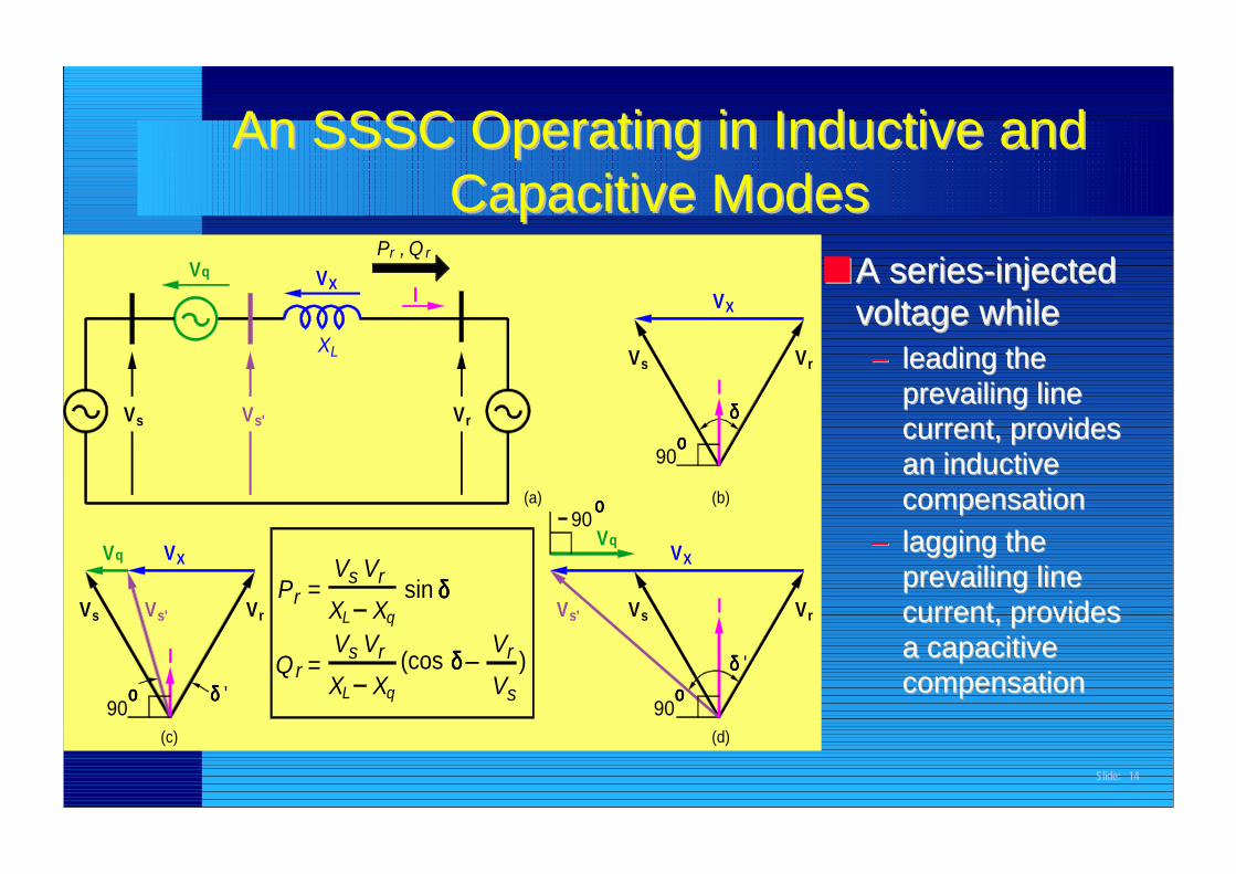
An SSSC Operating in Inductive andAn SSSC Operating in Inductive andCapacitiveCapacitive Modes Modes
■■ A series-injectedA series-injectedvoltage whilevoltage while–– leading theleading the
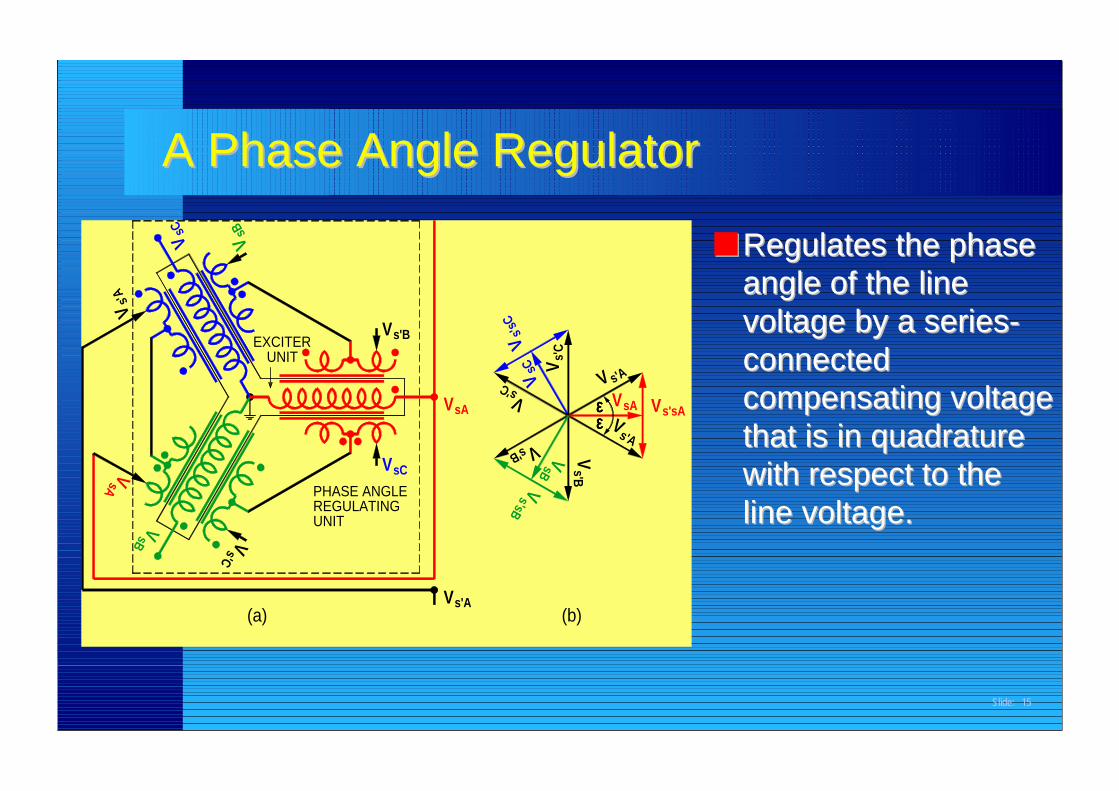
■■ Regulates the phaseRegulates the phaseangle of the lineangle of the linevoltage by a series-voltage by a series-connectedconnectedcompensating voltagecompensating voltagethat is in quadraturethat is in quadraturewith respect to thewith respect to theline voltage.line voltage.
A Phase Angle RegulatorA Phase Angle Regulator
s'B
sCPHASE ANGLEREGULATINGUNIT
V V
sA
sBV
(a)
s'CV
V
V
sC
s'A
VEXCITER
UNIT
VsB
s'B
sB
(b)s'AV
s'sBV
εεεεεεεε
V
s'sC
s'CVsA
V
s'B V
V V
VVs
C V s' C
sAV VV
s'sAs'A
s'A
Slide: 16
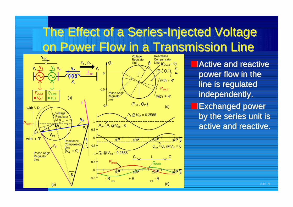
■■ Active and reactiveActive and reactivepower flow in thepower flow in theline is regulatedline is regulatedindependently.independently.
■■ Exchanged powerExchanged powerby the series unit isby the series unit isactive and reactive.active and reactive.
The Effect of a Series-Injected VoltageThe Effect of a Series-Injected Voltageon Power Flow in a Transmission Lineon Power Flow in a Transmission Line
Q
- R
Phase AngleRegulatorLine
P
V
1exchP X
Phase AngleRegulatorLine
(b)
with '+ R'ββββ
s'V
Vs
Vs's
-1 Qr @
δδδδ0
-0.5
0.5
r
δδδδ2
ReactanceCompensatorLine( = 0)Vd
V
0
-0.5
0.5P rn =
VoltageRegulatorLine
exch= V I
with '- R'
d
Pq= V I
exchQ
d
V
sV V q s'V
s's
V
-0.5
I
V
(a)
-1
X
XL
VrP ,
I r0
QV
r
270
270
LQ
Q
C
+ R
οοοο90
Pexch
180οοοο
οοοο90
= 0.2588s's
@r = 0Vs's
180οοοο
C
360οοοο
- R(c)
exch
οοοο ββββ
360
s's
οοοο
rn = Qr @V
οοοο ββββ= 0
= 0.2588rP
( )rnP , Qrn
@Vs's
r
1
VoltageRegulatorLine ββββ
Pexch
(d)
with '+ R'
P( = 0)
( )P , Qr* *r2
with '- R'
ReactanceCompensatorLine Pexch
r
Slide: 17
Characteristics of Power Flow ControllersCharacteristics of Power Flow Controllers■■ Traditional power flow controllersTraditional power flow controllers
–– each controls only one of the three parameters (voltage, reactance oreach controls only one of the three parameters (voltage, reactance orangle).angle).
■■ Single Voltage-Sourced Converter-based power flow controllersSingle Voltage-Sourced Converter-based power flow controllers–– each controls one of the transmission line parameters.each controls one of the transmission line parameters.–– can have fast dynamic response.can have fast dynamic response.
■■ Dual Voltage-Sourced Converter-based power flow controllersDual Voltage-Sourced Converter-based power flow controllers–– can exchange real power with the line and generate or absorb reactivecan exchange real power with the line and generate or absorb reactive
power.power.
Slide: 18
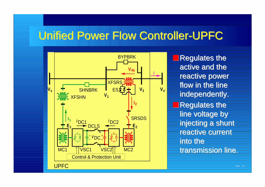
■■ Regulates theRegulates theactive and theactive and thereactive powerreactive powerflow in the lineflow in the lineindependently.independently.
■■ Regulates theRegulates theline voltage byline voltage byinjecting a shuntinjecting a shuntreactive currentreactive currentinto theinto thetransmission linetransmission line..
Unified Power Flow Controller-UPFCUnified Power Flow Controller-UPFC
VSC2Control & Protection Unit
MC1 VSC1
UPFC
iE1
I1
DCLS
vDC
DC1
VXFSHN
s SHNBRK
2I
MC2
iDC2 E2
SRSDS
V
1VES
XFSRSV2
dqI
BYPBRK
Vs'
Slide: 19
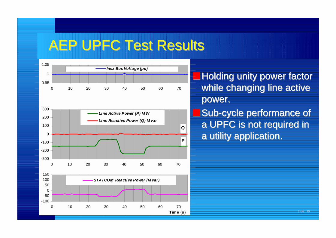
■■ Holding unity power factorHolding unity power factorwhile changing line activewhile changing line activepower.power.
■■ Sub-cycle performance ofSub-cycle performance ofa UPFC is not required ina UPFC is not required ina utility application.a utility application.
AEP UPFC Test ResultsAEP UPFC Test Results
P
Q
-300
-200
-100
0
100
200
300
0 10 20 30 40 50 60 70
Line Active Power (P) M W
Line Reactive Power (Q) M var
0.95
1
1.05
0 10 20 30 40 50 60 70
Inez Bus Voltage (pu)
-100-50
050
100150
0 10 20 30 40 50 60 70Time (s)
STATCOM Reactive Power (M var)
Slide: 20
What Are We Looking For in a Utility Application?What Are We Looking For in a Utility Application?
■■ A power flow controller that isA power flow controller that is–– reliablereliable–– independent regulator of active (independent regulator of active (PP) and reactive () and reactive (QQ) power flow) power flow–– fast enough for a utility applicationfast enough for a utility application–– inexpensiveinexpensive
Slide: 21
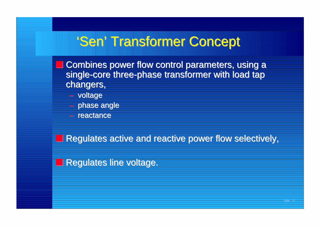
‘Sen’ Transformer Concept‘Sen’ Transformer Concept■■ Combines power flow control parameters, using aCombines power flow control parameters, using a
single-core three-phase transformer with load tapsingle-core three-phase transformer with load tapchangers,changers,–– voltagevoltage–– phase anglephase angle–– reactancereactance
■■ Regulates active and reactive power flow selectively,Regulates active and reactive power flow selectively,
■■ Regulates line voltage.Regulates line voltage.
Slide: 22
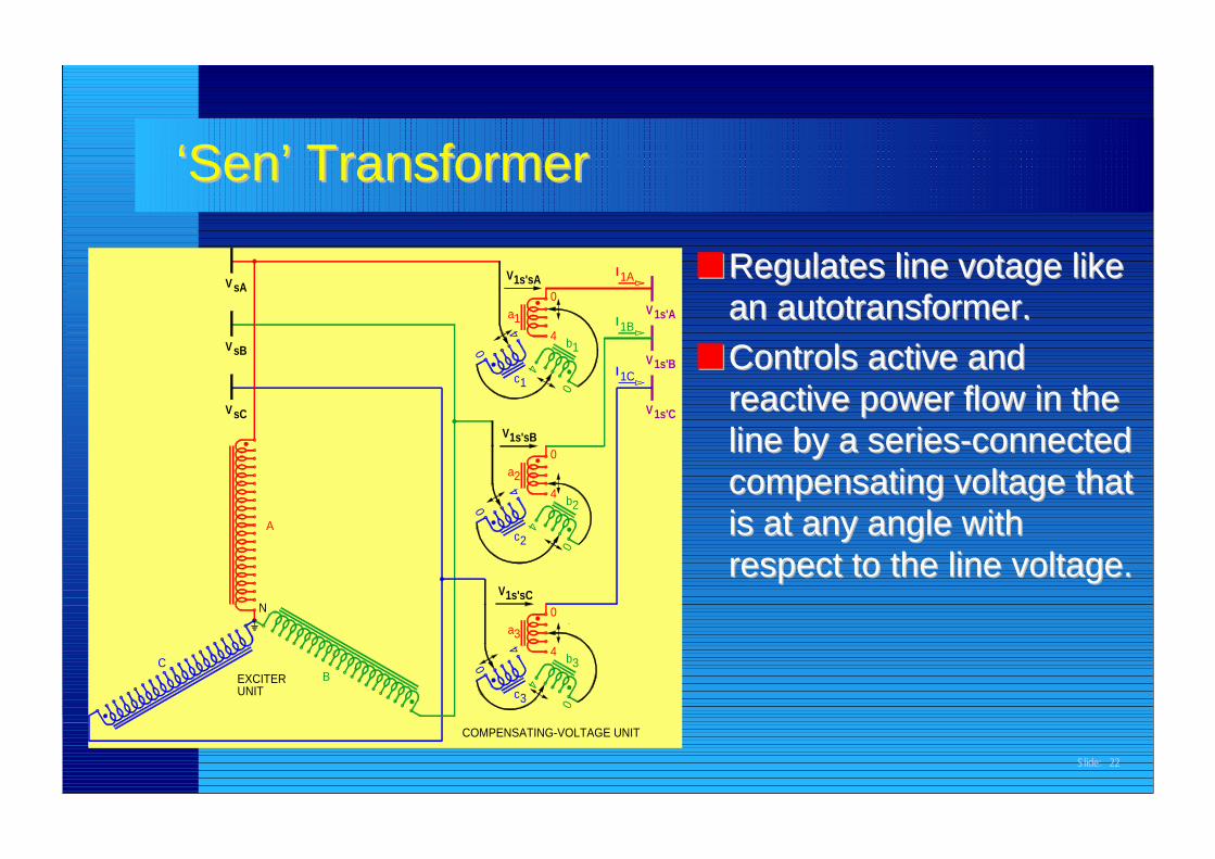
■■ Regulates line votage likeRegulates line votage likean autotransformer.an autotransformer.
■■ Controls active andControls active andreactive power flow in thereactive power flow in theline by a series-connectedline by a series-connectedcompensating voltage thatcompensating voltage thatis at any angle withis at any angle withrespect to the line voltage.respect to the line voltage.
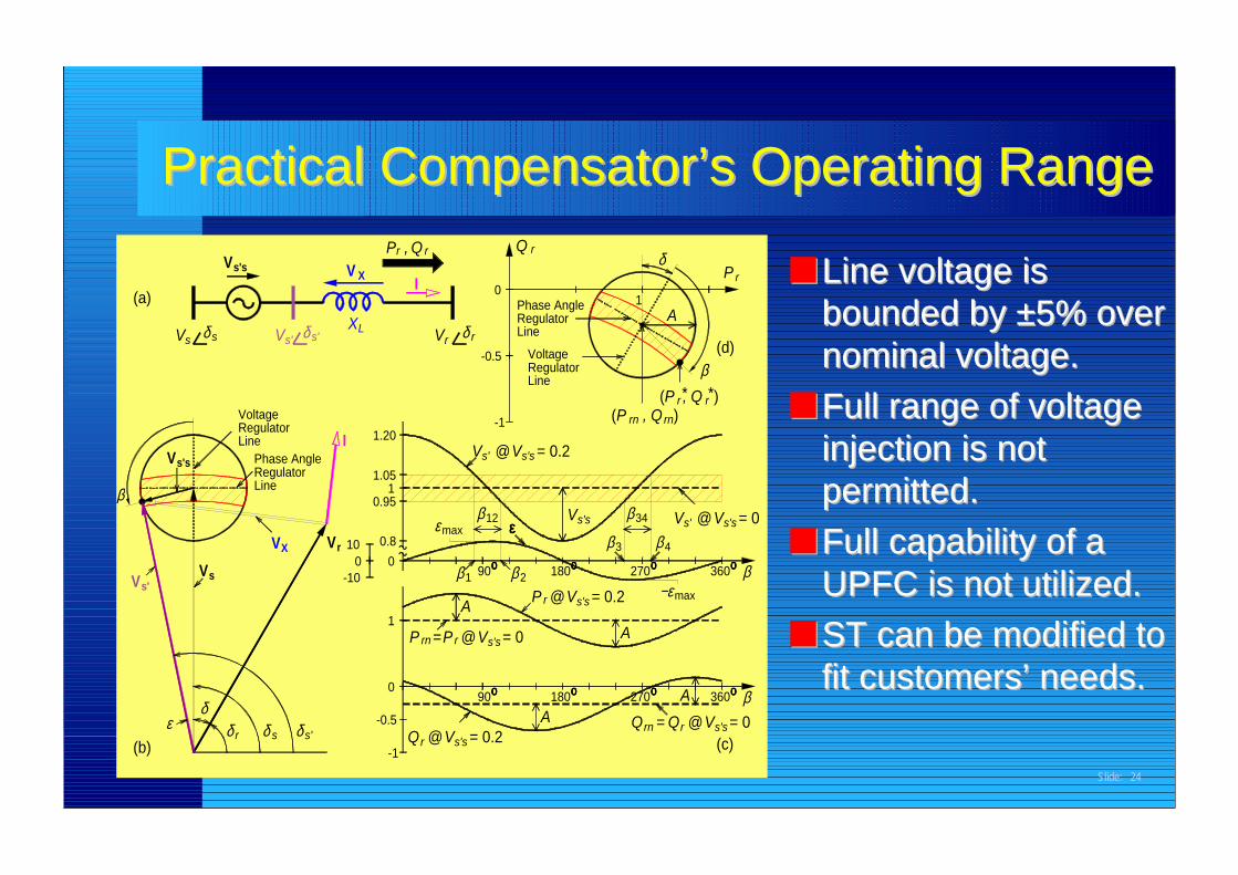
■■ Line voltage isLine voltage isbounded by ±5% overbounded by ±5% overnominal voltage.nominal voltage.
■■ Full range of voltageFull range of voltageinjection is notinjection is notpermitted.permitted.
■■ Full capability of aFull capability of aUPFC is not utilized.UPFC is not utilized.
■■ ST can be modified toST can be modified tofit customers’ needs.fit customers’ needs.
Practical Practical Compensator’sCompensator’s Operating Range Operating Range
V
max
P
1.051β
δ(b)
εδ
rδ
Vs'Vs
1P =
s s'δ
0
-1
-0.5Qr @
rn
-10
100
X rV V0
0.95
0.8ε
Phase AngleRegulatorLine
VoltageRegulatorLine
s sδ
Vs's
V
(a)
Vs's
rδ
I 1.20
X
LXVs' s'
VI
V
P , rr Q
270
270
Q
β
A@ = 0V
Aοοοο90
s's = 0.2
r s's
180οοοο
P
οοοο90 21
A
β β
12εεεε
β
οοοο3β
r @Vs's = 0.2180
s'sV
360
(c)s's
Aοοοο
r @Vrn = Q
οοοο β= 0
s's
360οοοο4β
max−ε
V Vs' @34
οοοο β
= 0
P , Qrn( )
-0.5 VoltageRegulatorLine
rδ
= 0.2
-1
s'ss'V V@
Phase AngleRegulatorLine
0
Q r
(d)
rn
P , Q* *( )r r
β
Pδ
1A
r
Slide: 25
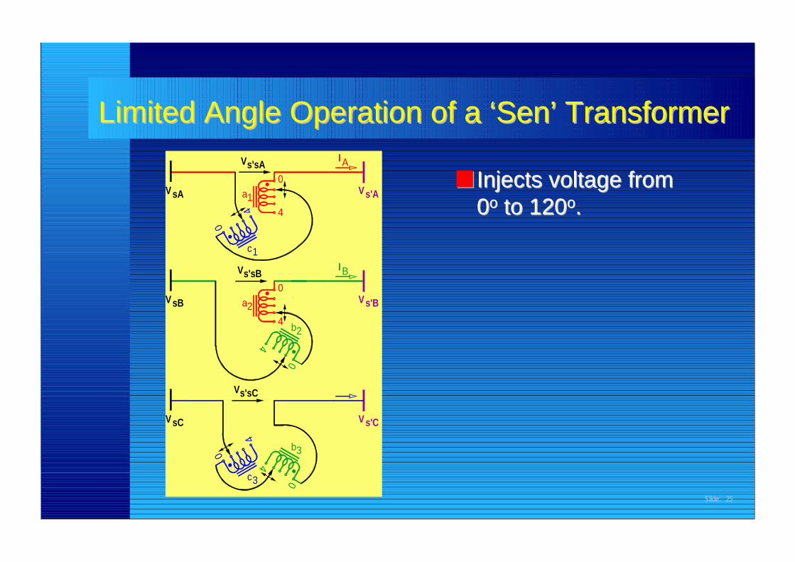
■■ Injects voltage fromInjects voltage from00οο to 120 to 120οο..
Limited Angle Operation of a ‘Limited Angle Operation of a ‘Sen’ TransformerSen’ Transformers'sA
44
VsC
0
4
c3
1c
VsB
Vs'sC
Vs'sB
a2
VsA a1
0
4
V
Vs'C
0
3b
b2
0
0
4
V
I B
s'B
0
4
s'AV
AI
Slide: 26
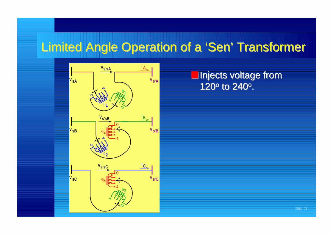
■■ Injects voltage fromInjects voltage from120120οο to 240 to 240οο..
Limited Angle Operation of a ‘Limited Angle Operation of a ‘Sen’ TransformerSen’ Transformer
4
s'sA
4
V sC a3
c1
V sB
0
2
Vs'sC
c
4
Vs'sB
a2
V sA
0
4
V
0V
0
43b
s'C
0
4
0
I C
V s'B
BI
b1
V s'A
I A
Slide: 27
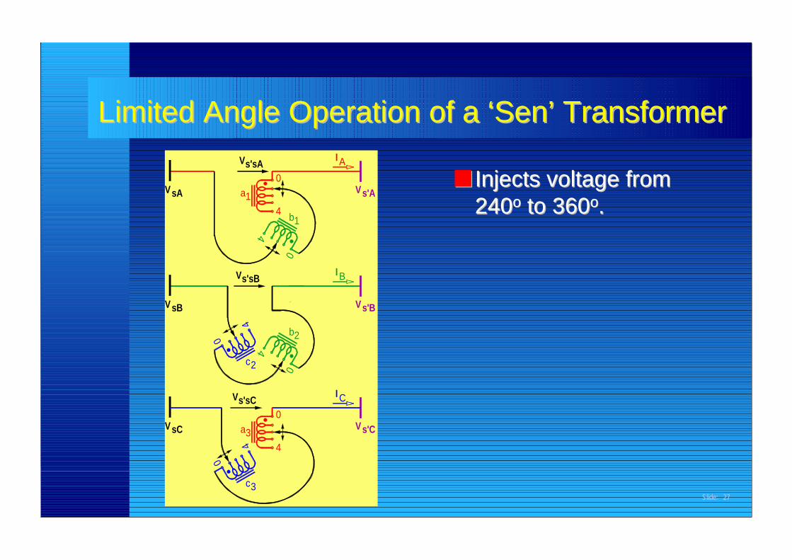
■■ Injects voltage fromInjects voltage from240240οο to 360 to 360οο..
Limited Angle Operation of a ‘Limited Angle Operation of a ‘Sen’ TransformerSen’ Transformers'sA
44
VsC
c3
0
4
a3
VsB
0
2
s'sCV
c
4
Vs'sB
VsA a1
V
0
4
Vs'C
0
b2
0
I C
Vs'B
I B
0
4 b1
s'AV
AI
Slide: 28
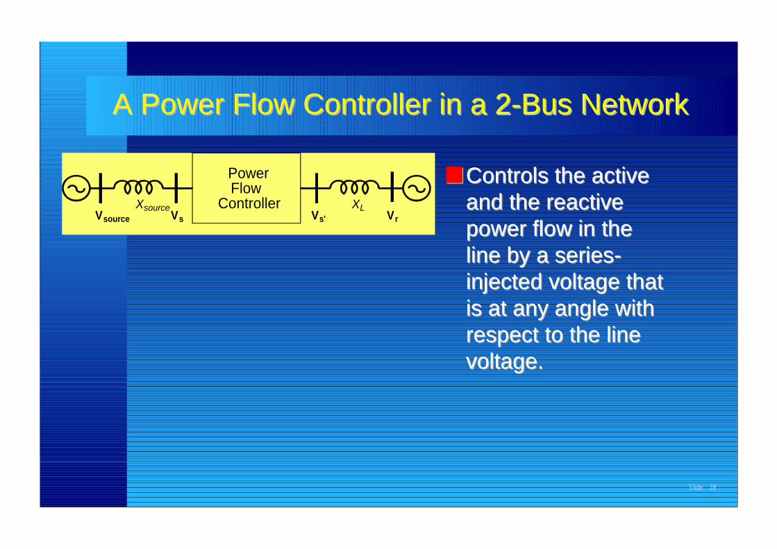
■■ Controls the activeControls the activeand the reactiveand the reactivepower flow in thepower flow in theline by a series-line by a series-injected voltage thatinjected voltage thatis at any angle withis at any angle withrespect to the linerespect to the linevoltage.voltage.
A Power Flow Controller in a 2-Bus NetworkA Power Flow Controller in a 2-Bus Network
VsourceVX
source
PowerFlow
ControllerVs V
XLs' r
Slide: 29
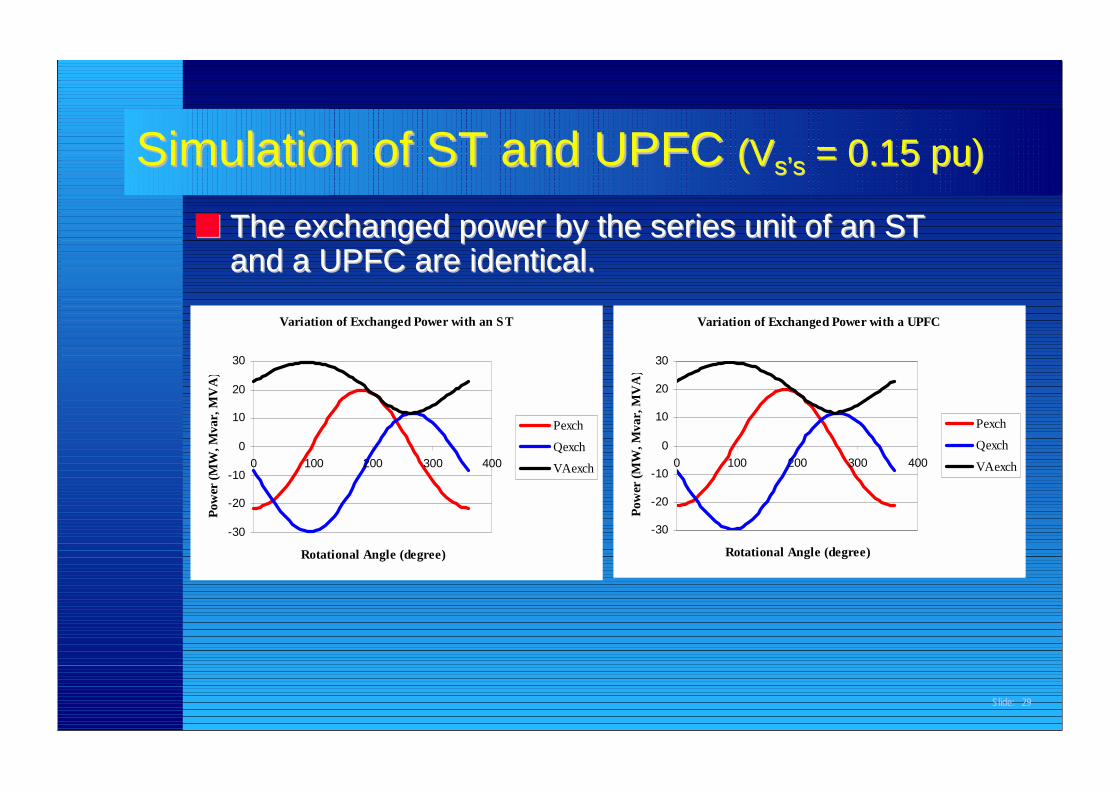
Simulation of ST and UPFC Simulation of ST and UPFC (V(Vs’ss’s = 0.15 pu) = 0.15 pu)
■■ The exchanged power by the series unit of an STThe exchanged power by the series unit of an STand a UPFC are identical.and a UPFC are identical.
Variation of Exchanged Power with an ST
-30
-20
-10
0
10
20
30
0 100 200 300 400
Rotational Angle (degree)
Pow
er (M
W, M
var,
MV
A)
Pexch
Qexch
VAexch
Variation of Exchanged Power with a UPFC
-30
-20
-10
0
10
20
30
0 100 200 300 400
Rotational Angle (degree)
Pow
er (M
W, M
var,
MV
A)
Pexch
Qexch
VAexch
Slide: 30
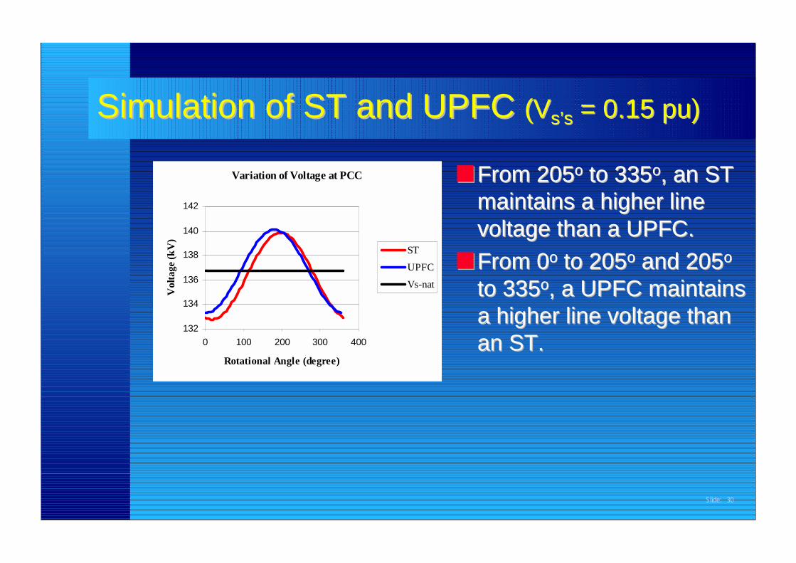
■■ From 205From 205οο to 335 to 335οο, an ST, an STmaintains a higher linemaintains a higher linevoltage than a UPFC.voltage than a UPFC.
■■ From 0From 0οο to 205 to 205οο and 205 and 205οο
to 335to 335οο, a UPFC maintains, a UPFC maintainsa higher line voltage thana higher line voltage thanan ST.an ST.
Variation of Voltage at PCC
132
134
136
138
140
142
0 100 200 300 400
Rotational Angle (degree)
Vol
tage
(kV
)
ST
UPFC
Vs-nat
Simulation of ST and UPFC Simulation of ST and UPFC (V(Vs’ss’s = 0.15 pu) = 0.15 pu)
Slide: 31
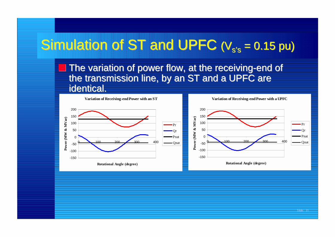
■■ The variation of power flow, at the receiving-end ofThe variation of power flow, at the receiving-end ofthe transmission line, by an ST and a UPFC arethe transmission line, by an ST and a UPFC areidentical.identical.
Variation of Receiving-end Power with an ST
-150
-100
-50
0
50
100
150
200
0 100 200 300 400
Rotational Angle (degree)
Pow
er (M
W &
MV
ar)
Pr
Qr
Pnat
Qnat
Variation of Receiving-end Power with a UPFC
-150
-100
-50
0
50
100
150
200
0 100 200 300 400
Rotational Angle (degree)
Pow
er (M
W &
MV
ar)
Pr
Qr
Pnat
Qnat
Simulation of ST and UPFC Simulation of ST and UPFC (V(Vs’ss’s = 0.15 pu) = 0.15 pu)
Slide: 32
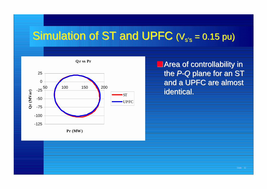
■■ Area of controllability inArea of controllability inthe the P-QP-Q plane for an ST plane for an STand a UPFC are almostand a UPFC are almostidentical.identical.
Q r vs Pr
-125
-100
-75
-50
-25
0
25
50 100 150 200
Pr (MW)
Qr
(MV
ar)
ST
UPFC
Simulation of ST and UPFC Simulation of ST and UPFC (V(Vs’ss’s = 0.15 pu) = 0.15 pu)
Slide: 33
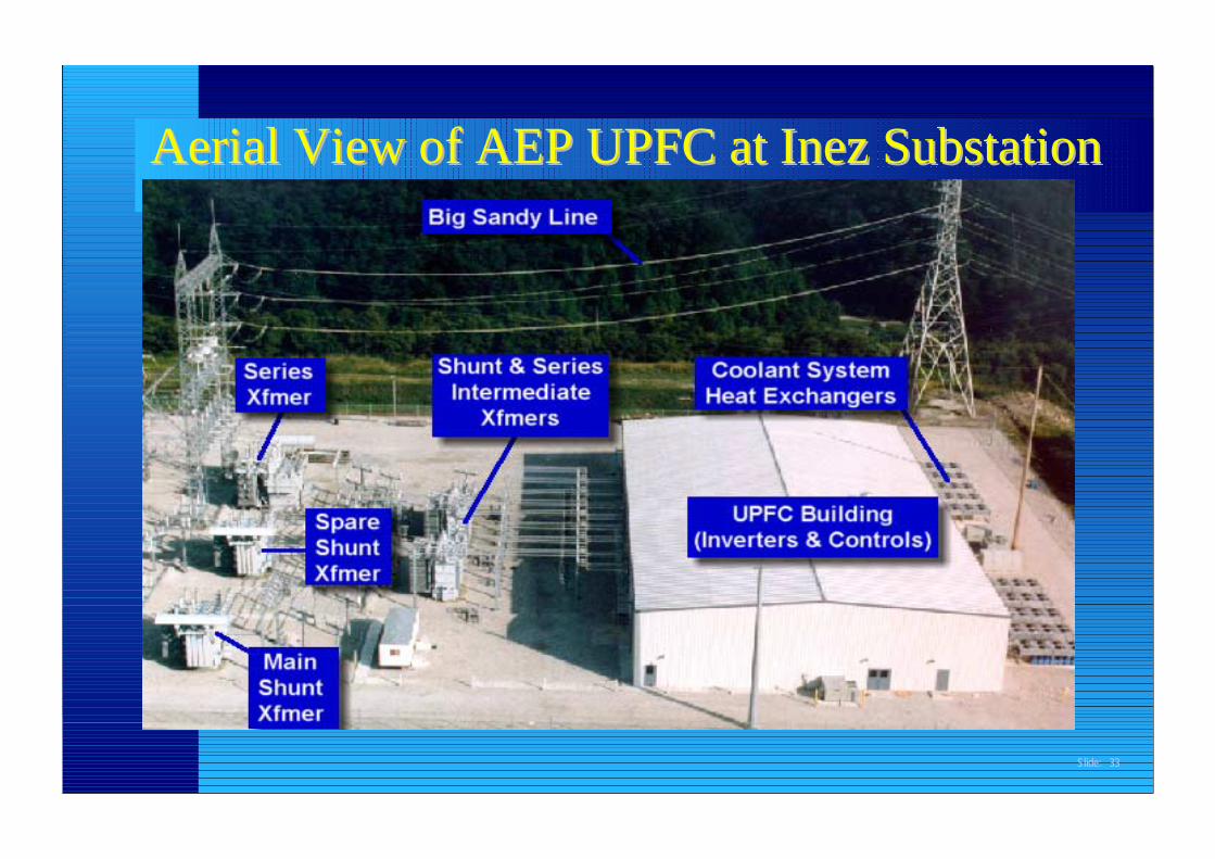
Aerial View of AEP UPFC at Inez SubstationAerial View of AEP UPFC at Inez Substation
Slide: 34
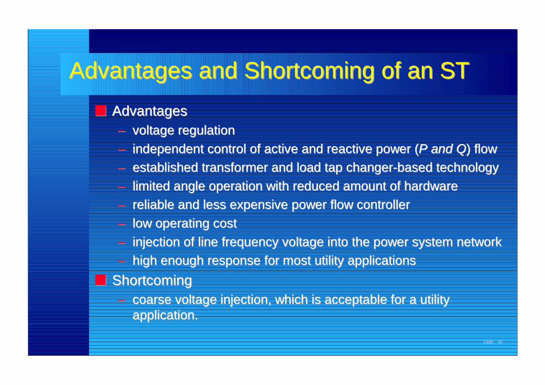
Advantages and Shortcoming of an STAdvantages and Shortcoming of an ST■■ AdvantagesAdvantages
–– voltage regulationvoltage regulation–– independent control of active and reactive power (independent control of active and reactive power (P and QP and Q) flow) flow–– established transformer and load tap changer-based technologyestablished transformer and load tap changer-based technology–– limited angle operation with reduced amount of hardwarelimited angle operation with reduced amount of hardware–– reliable and less expensive power flow controllerreliable and less expensive power flow controller–– low operating costlow operating cost–– injection of line frequency voltage into the power system networkinjection of line frequency voltage into the power system network–– high enough response for most utility applicationshigh enough response for most utility applications
■■ ShortcomingShortcoming–– coarse voltage injection, which is acceptable for a utilitycoarse voltage injection, which is acceptable for a utility
application.application.
Slide: 35
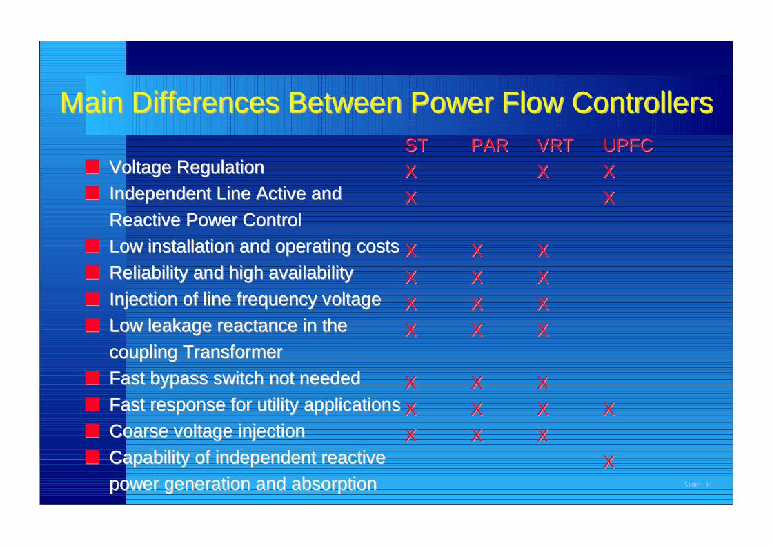
Main Differences Between Power Flow ControllersMain Differences Between Power Flow Controllers
■■ Voltage RegulationVoltage Regulation■■ Independent Line Active andIndependent Line Active and
Reactive Power ControlReactive Power Control■■ Low installation and operating costsLow installation and operating costs■■ Reliability and high availabilityReliability and high availability■■ Injection of line frequency voltageInjection of line frequency voltage■■ Low leakage reactance in theLow leakage reactance in the
coupling Transformercoupling Transformer■■ Fast bypass switch not neededFast bypass switch not needed■■ Fast response for utility applicationsFast response for utility applications■■ Coarse voltage injectionCoarse voltage injection■■ Capability of independent reactiveCapability of independent reactive
power generation and absorptionpower generation and absorption
STST PARPAR VRTVRT UPFCUPFCXX X X XXXX XX
XX XX XXXX XX XXXX XX XXXX XX XX
XX XX XXXX XX XX XXXX XX XX
XX
Slide: 36
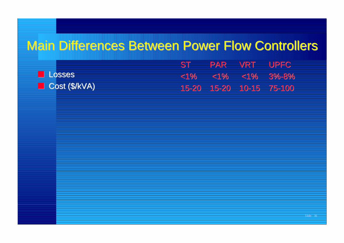
Main Differences Between Power Flow ControllersMain Differences Between Power Flow Controllers
ConclusionConclusion■■ A new power flow controlling transformer is presented.A new power flow controlling transformer is presented.■■ ‘Sen’ Transformer‘Sen’ Transformer
–– uses traditional technology of transformer and tap changers.uses traditional technology of transformer and tap changers.–– uses proven technology that is reliable.uses proven technology that is reliable.–– provides four quadrant control of active power (provides four quadrant control of active power (PP) and) and
reactive power (reactive power (QQ) for an optimum system operation.) for an optimum system operation.–– provides more features than a PAR at the same cost.provides more features than a PAR at the same cost.–– displaces UPFC for most utility applications.displaces UPFC for most utility applications.
■■ An emerging power flow controller market can beAn emerging power flow controller market can beexploited with the right technology.exploited with the right technology.