23
Recent progress of GFR program JY. Garnier, JY. Malo, F. Bertrand, P. Anzieu Presented by N. Devictor Nuclear Energy Directorate CEA Cadarache, CEA Saclay FRANCE

Recent progress of GFR programJY. Garnier, JY. Malo, F. Bertrand, P. Anzieu
Presented by N. Devictor
Nuclear Energy DirectorateCEA Cadarache, CEA Saclay
FRANCE

CEA/DEN/DER Nov. 09, FR09, Tokyo, Japan 2
OutlinesAn alternative Fast reactor to SFR• Main assets, reactor specificationsOverview of the main design options, zoom on:• Fuel, core• Reactor pressure vessel, primary circuit• Safeguard, Decay Heat Removal systems• Overall plant layoutPreliminary safety analysis• Safety approach• DBA situations• DEC situations• PSA in support of the design• Severe accidentsConclusion

CEA/DEN/DER Nov. 09, FR09, Tokyo, Japan 3
To combine Fast spectrum & helium coolant benefits
Safety (He) • Great neutron transparency, attractive gas voiding reactivity effect < 1$• No threshold effect: single phase cooling, chemical inertness (air, water) • Potential for In-Service Inspection, T° instrumentation: optical transparency
Competitivness (He) • High temperature, potential for: – high energy conversion efficiency (45% - 48%) – a broad range of non electricity industrial applications (process heat, hydrogen, synthetic fuels…)
• Simplified management potential for repairing & dismantling: non toxic coolant, not activated, optical transparency
Fuel management (fast spectrum) • Efficient use of natural ressources: Pu generation• Potential for ultimate waste minimization: multi-recycling of all actinides
Some significant assets and a real potential
A promising concept, with other merits than the SFRInnovative and challenging concept, demanding a fuel technology able to
withstand high temperatures
H2O 150 bar
He-N2 65 bar He
70 bar
850°C
400°C
820°C 535°C
32°C 178°C 362°C
565°C
Electrical grid
The GFR: an alternative FR for longer-term
CEA/DEN/DER Nov. 09, FR09, Tokyo, Japan 4
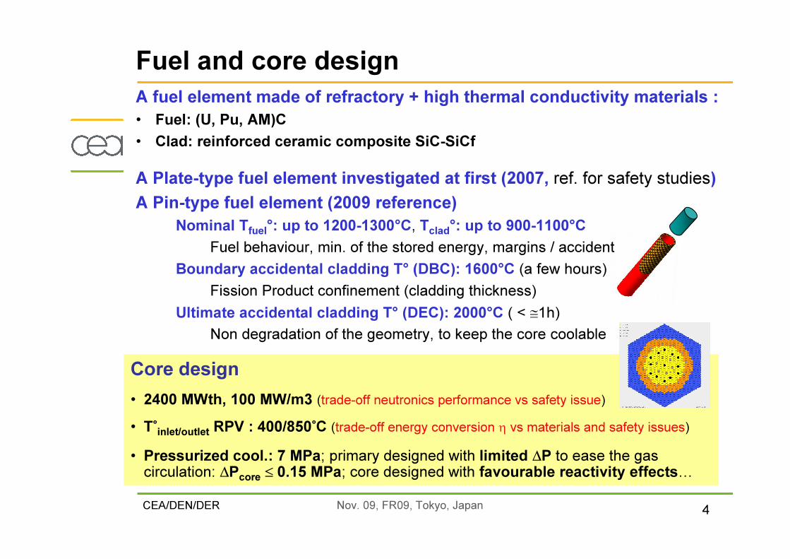
Fuel and core design
Core design• 2400 MWth, 100 MW/m3 (trade-off neutronics performance vs safety issue) • T°inlet/outlet RPV : 400/850°C (trade-off energy conversion η vs materials and safety issues) • Pressurized cool.: 7 MPa; primary designed with limited ∆P to ease the gas circulation: ∆Pcore ≤ 0.15 MPa; core designed with favourable reactivity effects…
A fuel element made of refractory + high thermal conductivity materials :• Fuel: (U, Pu, AM)C• Clad: reinforced ceramic composite SiC-SiCf
A Plate-type fuel element investigated at first (2007, ref. for safety studies)A Pin-type fuel element (2009 reference)
Nominal Tfuel°: up to 1200-1300°C, Tclad°: up to 900-1100°CFuel behaviour, min. of the stored energy, margins / accident
Boundary accidental cladding T° (DBC): 1600°C (a few hours)Fission Product confinement (cladding thickness)
Ultimate accidental cladding T° (DEC): 2000°C ( < ≅1h)Non degradation of the geometry, to keep the core coolable
CEA/DEN/DER Nov. 09, FR09, Tokyo, Japan 5
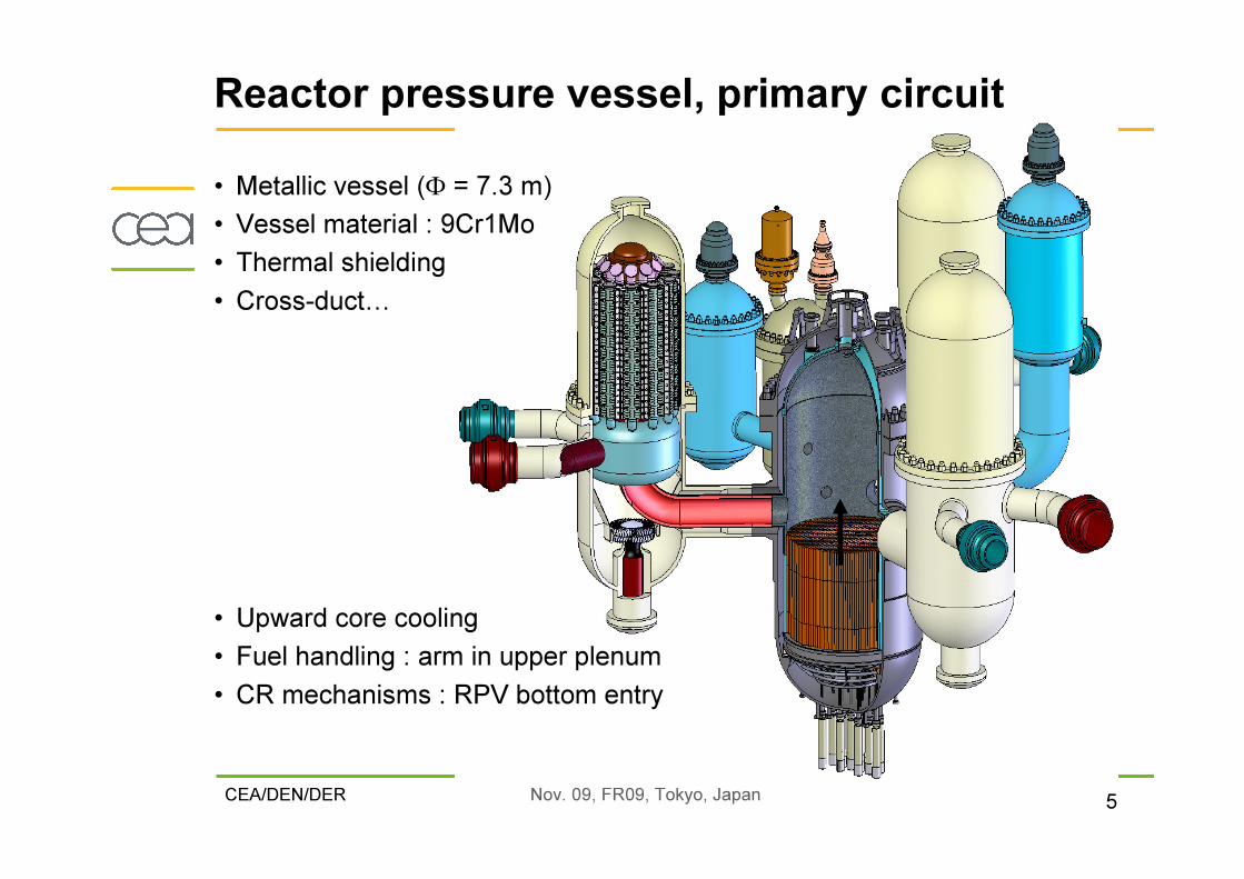
Reactor pressure vessel, primary circuit
• Upward core cooling• Fuel handling : arm in upper plenum• CR mechanisms : RPV bottom entry
• Metallic vessel (Φ = 7.3 m) • Vessel material : 9Cr1Mo• Thermal shielding• Cross-duct…
CEA/DEN/DER Nov. 09, FR09, Tokyo, Japan 6
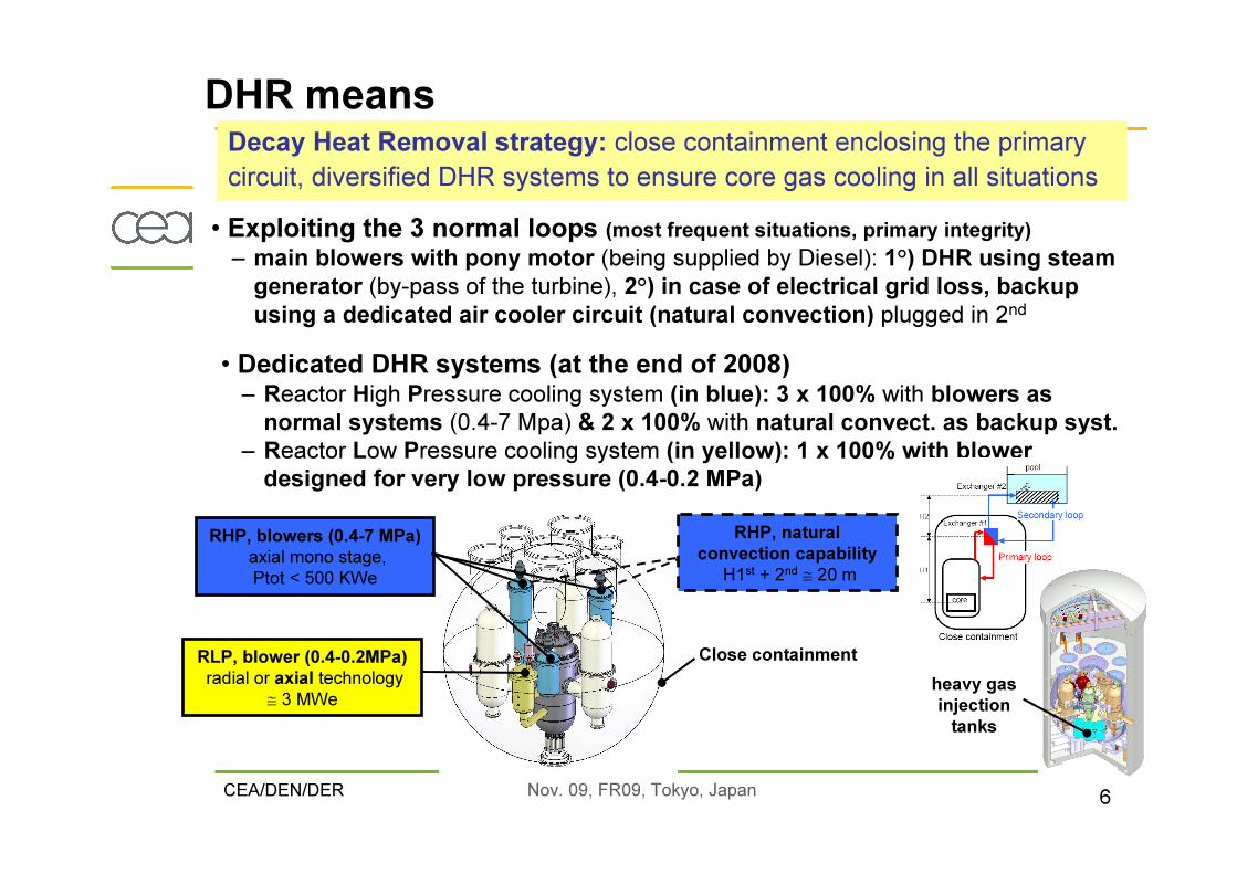
• Dedicated DHR systems (at the end of 2008)– Reactor High Pressure cooling system (in blue): 3 x 100% with blowers as normal systems (0.4-7 Mpa) & 2 x 100% with natural convect. as backup syst.
– Reactor Low Pressure cooling system (in yellow): 1 x 100% with blower designed for very low pressure (0.4-0.2 MPa)
Decay Heat Removal strategy: close containment enclosing the primarycircuit, diversified DHR systems to ensure core gas cooling in all situations
RHP, blowers (0.4-7 MPa)axial mono stage,Ptot < 500 KWe
Close containment
RHP, naturalconvection capability
H1st + 2nd ≅ 20 m
RLP, blower (0.4-0.2MPa)radial or axial technology
≅ 3 MWe
• Exploiting the 3 normal loops (most frequent situations, primary integrity)– main blowers with pony motor (being supplied by Diesel): 1°) DHR using steam generator (by-pass of the turbine), 2°) in case of electrical grid loss, backup using a dedicated air cooler circuit (natural convection) plugged in 2nd
heavy gasinjection tanks
DHR means

CEA/DEN/DER Nov. 09, FR09, Tokyo, Japan 7
GFR 2400 MWth, overall plant layout
Spent & fresh fuel storage
Reactorplant
Nuclear SteamSupply System
(tertiary)
Gas Turbine Conversion System(secondary, x 3) Diesels
Control command
(x 2)
Gas tanks storage

CEA/DEN/DER Nov. 09, FR09, Tokyo, Japan 8
1- Governing principles� Defence in depth (DiD) concept� Principle of physical barriers� The safety functions � ALARA approach for radiation protection
2- General frame of the safety analysis� Identification and preliminary categorization of initiating events (IEs)� Deterministic rules for the safety analysis
� Categorization of bounding situations resulting from IE + single aggravatingfailure (only the safety systems are considered available for DBAs)
� Categorization of complex sequences
� Combination of deterministic and probabilistic methods� LOP, study of operating conditions, PSA and feed-back on categorization� Objective provision trees as an help to draw an invetory of safety provisions
Safety approach (1/2)

CEA/DEN/DER Nov. 09, FR09, Tokyo, Japan 9
Safety approach (2/2)

CEA/DEN/DER Nov. 09, FR09, Tokyo, Japan 10
�Objectives : assessment of the performance and of the robustness of the DHR system (DBA), including cross failures (DEC)�Situations considered :
DBAs : 100 % PN + EI + single aggravating failure� Intermediate states still to be addressed
DEC : � 100 % PN + EI (DEC)� Complex sequences � 100 % PN + EI (DBA) + multiple failures
�Acceptance criteria :category 3 situations :
upper plenum temperature < 1250°C ; clad temperature < 1450°Ccategory 4 situations, the more limiting criterion being considered among :
fuel temperature < 2000°C ; clad temperature < 1600°Cupper plenum temperature < 1250°C ;no degradation of the fluid channel able to prevent the core cooling ;
category 3 and 4 :controlled state must be reached at the end of the sequence
�Single agravating failure consideredthe failure of a Diesel trainthe failure of a blower when actuatedthe failure of the opening of a DHR loopthe failure of the closing of a main loop� The one having the most adverse effect is considered for each IE
Deterministic analysis (1/2)

CEA/DEN/DER Nov. 09, FR09, Tokyo, Japan 11
LOCAs preliminary discrimination and classification status� Small leaks compensable with the HSS (limit size to be defined)�Category 2
� Small breaks controllable with natural convection (heavy gas injection) in case of failure of the forced convection means� up to 3 inches, category 3
� Large breaks� Inducing a reverse flow in the core (could require an additional decoupling criterion on the cooling transient on clads and vessel)� larger than 3 inches, Category 4
Deterministic analysis (2/2)

CEA/DEN/DER Nov. 09, FR09, Tokyo, Japan 12
CATHARE2 calculation of a 1inch break (cat. 3 accident) pressure transient
CATHARE2 calculation of a 10 inches break (cat. 4 accident) temperature and flow rate transient
Lowerplenum and containment pressures
0.E+00
1.E+06
2.E+06
3.E+06
4.E+06
5.E+06
6.E+06
7.E+06
0 3000 6000 9000 12000 15000Time (s)
Pres
sure
(b)
LowerplenumContainment
Core temperature (z=4.05m)
-200
0
200
400
600
800
1000
1200
1400
0 10 20 30 40 50 60
Time (s)
Temp
eratur
e (°C
)
-200
0
200
400
600
800
1000
1200
1400
Mass
flow
rate (
kg/s)
FuelCladHeliumCore mass flow rate
Some examples of transients (DBA Conditions)
CEA/DEN/DER Nov. 09, FR09, Tokyo, Japan 13
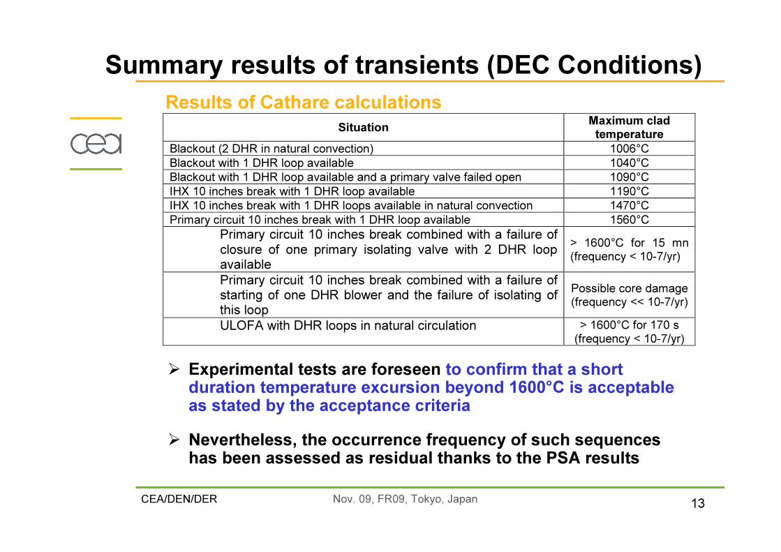
Results of Cathare calculations
� Experimental tests are foreseen to confirm that a short duration temperature excursion beyond 1600°C is acceptable as stated by the acceptance criteria� Nevertheless, the occurrence frequency of such sequences has been assessed as residual thanks to the PSA results
Situation Maximum clad temperature
Blackout (2 DHR in natural convection) 1006°C Blackout with 1 DHR loop available 1040°C Blackout with 1 DHR loop available and a primary valve failed open 1090°C IHX 10 inches break with 1 DHR loop available 1190°C IHX 10 inches break with 1 DHR loops available in natural convection 1470°C Primary circuit 10 inches break with 1 DHR loop available 1560°C
Primary circuit 10 inches break combined with a failure of closure of one primary isolating valve with 2 DHR loop available
> 1600°C for 15 mn (frequency < 10-7/yr)
Primary circuit 10 inches break combined with a failure of starting of one DHR blower and the failure of isolating of this loop
Possible core damage (frequency << 10-7/yr)
ULOFA with DHR loops in natural circulation > 1600°C for 170 s (frequency < 10-7/yr)
Summary results of transients (DEC Conditions)

CEA/DEN/DER Nov. 09, FR09, Tokyo, Japan 14
�Level 1 PSA as a support to the reactor design� Identification of plant vulnerabilities� System interdependencies and common cause failures (CCFs)� Examination of risk benefits of various design options� Will help to design optimization of safety systems in terms of redundancy and diversification (the definition of the DHR means already takes into account the early results of the PSA analysis)
�Initiating events considered� Consistent with the deterministic analysis (LOOP, LOFA, LOCA)� Plus inadvertent reactor trip
�ResultsIdentification of the major contributors in the Core Damage Frequency : failure of the reactivity control and failure of the isolation of IHX 2nd circuit
Probabilistic analysis
100%
45%
5% 3%0
0.10.20.30.40.50.60.70.80.91
Référence Variante 1 Variante 2 Variante 3
GFR 2400 MWth Probabilistic Engineering Assessment v1Improvement of CDF by support systems modifications
Redundancy of voting systems
Case #1+ diversification of the signal
for DHR actuation
Case #2+ redundancy of electrical supplies for DHR isolating valves closing
(bypass concern)
Reference Case #1 Case #2 Case #3
Reduction by a factor 40of the total CDF
Impact of design changes on core damage frequency
CEA/DEN/DER Nov. 09, FR09, Tokyo, Japan 15
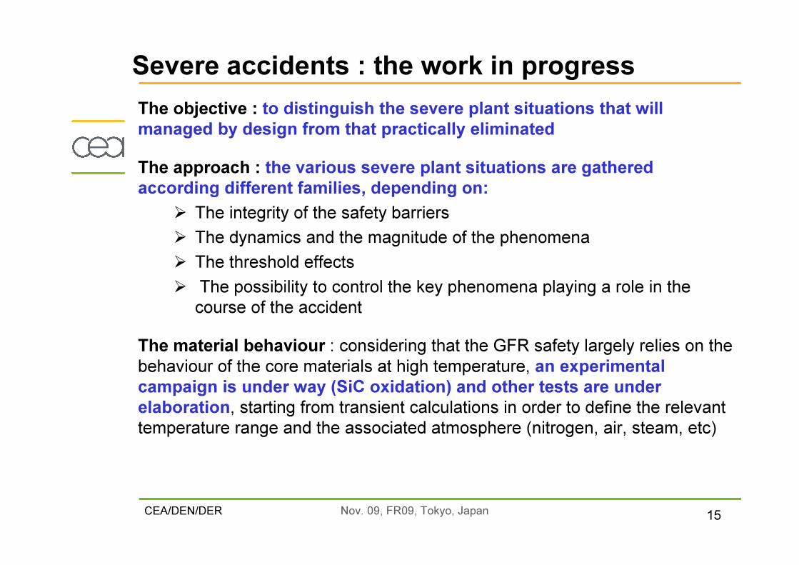
The objective : to distinguish the severe plant situations that will managed by design from that practically eliminatedThe approach : the various severe plant situations are gathered according different families, depending on:� The integrity of the safety barriers� The dynamics and the magnitude of the phenomena� The threshold effects� The possibility to control the key phenomena playing a role in the course of the accident
The material behaviour : considering that the GFR safety largely relies on the behaviour of the core materials at high temperature, an experimental campaign is under way (SiC oxidation) and other tests are under elaboration, starting from transient calculations in order to define the relevant temperature range and the associated atmosphere (nitrogen, air, steam, etc)
Severe accidents : the work in progress
CEA/DEN/DER Nov. 09, FR09, Tokyo, Japan 16
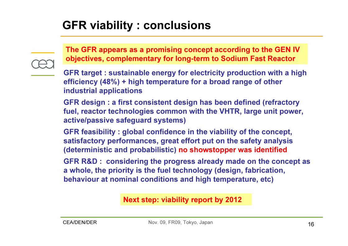
GFR target : sustainable energy for electricity production with a high efficiency (48%) + high temperature for a broad range of other industrial applicationsGFR design : a first consistent design has been defined (refractory fuel, reactor technologies common with the VHTR, large unit power, active/passive safeguard systems)GFR feasibility : global confidence in the viability of the concept, satisfactory performances, great effort put on the safety analysis (deterministic and probabilistic) no showstopper was identifiedGFR R&D : considering the progress already made on the concept as a whole, the priority is the fuel technology (design, fabrication, behaviour at nominal conditions and high temperature, etc)
GFR viability : conclusionsThe GFR appears as a promising concept according to the GEN IV objectives, complementary for long-term to Sodium Fast Reactor
Next step: viability report by 2012

CEA/DEN/DER Nov. 09, FR09, Tokyo, Japan 17
BACK-UP
CEA/DEN/DER Nov. 09, FR09, Tokyo, Japan 18
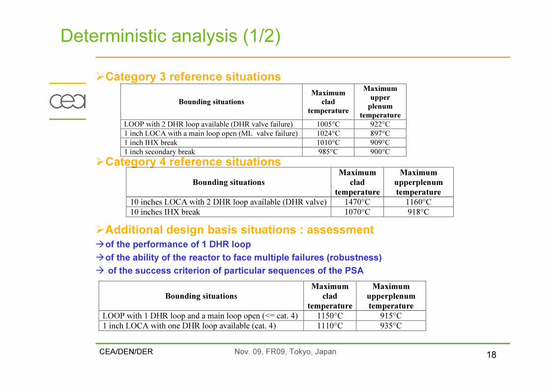
�Category 3 reference situations
�Category 4 reference situations
�Additional design basis situations : assessment �of the performance of 1 DHR loop�of the ability of the reactor to face multiple failures (robustness)� of the success criterion of particular sequences of the PSA
Deterministic analysis (1/2)
Bounding situations Maximum
clad temperature
Maximum upper
plenum temperature
LOOP with 2 DHR loop available (DHR valve failure) 1005°C 922°C 1 inch LOCA with a main loop open (ML valve failure) 1024°C 897°C 1 inch IHX break 1010°C 909°C 1 inch secondary break 985°C 900°C
Bounding situations Maximum
clad temperature
Maximum upperplenum temperature
10 inches LOCA with 2 DHR loop available (DHR valve) 1470°C 1160°C 10 inches IHX break 1070°C 918°C
Bounding situations Maximum
clad temperature
Maximum upperplenum temperature
LOOP with 1 DHR loop and a main loop open (<= cat. 4) 1150°C 915°C 1 inch LOCA with one DHR loop available (cat. 4) 1110°C 935°C
CEA/DEN/DER Nov. 09, FR09, Tokyo, Japan 19
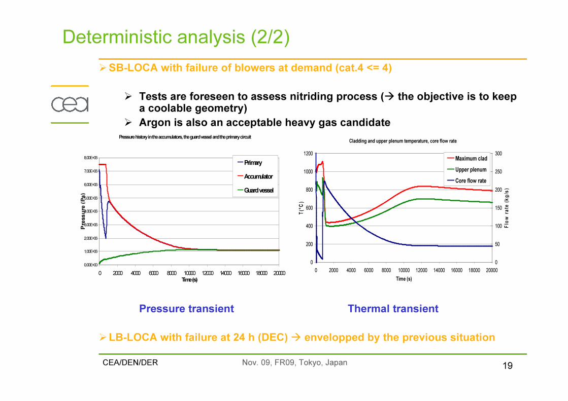
�SB-LOCA with failure of blowers at demand (cat.4 <= 4)
� Tests are foreseen to assess nitriding process (� the objective is to keepa coolable geometry)
� Argon is also an acceptable heavy gas candidate
Pressure transient Thermal transient
�LB-LOCA with failure at 24 h (DEC) � envelopped by the previous situation
Deterministic analysis (2/2)
Pressure history in the accumulators, the guard vessel and the primary circuit
0,00E+00
1,00E+06
2,00E+06
3,00E+06
4,00E+06
5,00E+06
6,00E+06
7,00E+06
8,00E+06
0 2000 4000 6000 8000 10000 12000 14000 16000 18000 20000Time (s)
Pres
sure
(Pa)
PrimaryAccumulatorGuard vessel
Cladding and upper plenum temperature, core flow rate
0
200
400
600
800
1000
1200
0 2000 4000 6000 8000 10000 12000 14000 16000 18000 20000Time (s)
T(°C)
0
50
100
150
200
250
300
Flow
rate (
kg/s)
Maximum cladUpper plenumCore flow rate

CEA/DEN/DER Nov. 09, FR09, Tokyo, Japan 20
�Level 1 PSA a a support to the reactor design� Identification of plant vulnerabilities� System interdependencies and common cause failures (CCFs)� Examination of risk benefits of various design options� Will help to design optimization of safety systems in terms of redundancy and diversification
�Initiating events considered� Consistent with the deterministic analysis (LOOP, LOFA, LOCA)� Plus inadvertent reactor trip� All IEs will be taken into account in the next version of the PSA
�Consideration about uncertainties� Reliability of natural convection with a specific methodology (FP5 : RMPS)� Technological uncertainty associated to very innovative components� Physical uncertainty due to the performance of an innovative system� Investigation on the most relevant failure rates for components and associated approach
Probabilistic analysis (1/3)

CEA/DEN/DER Nov. 09, FR09, Tokyo, Japan 21
Probabilistic analysis (2/3) : sketch of the PSA modelling
freq/y
Ev. A Ev. B Ev. C Ev. DOKEvR2EvR1EvR1EvR1
A
Basicevent
A’
Additional system
Dependancies
Ev. X
Failure rates of components
Redundancy
Occurrence frequency
of IEs
Modification of existingsystems
Event Trees (Ets)
Fault trees (FTs)
ListIEs

CEA/DEN/DER Nov. 09, FR09, Tokyo, Japan 22
�Design improvments through the PSA (signal elaboration is considered)
� The PSA brought a complementaryapproach not only focused on systemperformance but also on their abilityto be actuated
�Other lessons learned from the PSA� Prioritization of R&D effort (design, study of severe accidents)� The robustness of the DHR system must be improved for frequent pressurized situations (however
current approach is very conservative : only DHR loops)� Dependencies within the DHR system will be reduced
Probabilistic analysis (3/3) : feed-back on design
100%
45%
5% 3%0
0.10.20.30.40.50.60.70.80.91
Référence Variante 1 Variante 2 Variante 3
GFR 2400 MWth Probabilistic Engineering Assessment v1Improvement of CDF by support systems modifications
Redundancy of voting systems
Case #1+ diversification of the signal
for DHR actuation
Case #2+ redundancy of electrical supplies for DHR isolating valves closing
(bypass concern)
Reference Case #1 Case #2 Case #3
Reduction by a factor 40of the total CDF

CEA/DEN/DER Nov. 09, FR09, Tokyo, Japan 23
�Conclusions from DBAs analysis� Good performance of the DHR system in FC and NC� Low power blowers that can be supplied by NC for pressurized situations and for SB-LOCAs as
well as for the long term control of LB-LOCAs� Considering the dimensionning and the robustness of te DHR system (redondancy and
diversification), by-pass situations due to wrong primary flow pathway permit to fulfill te decoupling criteria with a comfortable margin in most of the situations including te fastdepressurization transients associated to a more limited margin.
�Conclusions from DECs analysis� The approach is up to now very conservative because all the systems should be assumed available
as in our studies, the HSS and the main loops are not actuated but should be considered for riskreduction of frequent initiating events as suggested by PSA results
� Complex sequences at nominal and intermediate pressure can be controlled, even in NC� The study of very hypothetical situations resulting from fast depressurizations combined to
multiple failures leading to core by-pass had underlined the necessity to have support systemsenabling the risk of wrong circuit configuration to be reduced (the same conclusions have been drawn from the PSA)
� PSA enabled to I/C system to be reinforced, thus leading to a large safety improvment
� Futur work� The scope of the analysis will be extended (deterministic and PSA)� Consideration of the use of the main loops and of the HSS� Improvment of redundancy and diversification of flow pathway configuration components
Conclusions


