Shiro WATAKABE Assistant Sub Project Leader of COURSE50 JFE Steel Corp. Current Progress on COURSE50 Project -- Recent Results on H 2 Reduction including LKAB’s EBF Experiments and CO 2 Capture -- 5th November 2013 at Tokyo Institute of Technology IEAGHG/IETS Iron & Steel Industry CCUS & Process Integration Workshop
Transcript
1
Shiro WATAKABE
Assistant Sub Project Leader of COURSE50JFE Steel Corp.
Current Progress on COURSE50 Project
-- Recent Results on H2 Reduction including LKAB’s EBF Experiments and CO2 Capture --
5th November 2013at Tokyo Institute of Technology
IEAGHG/IETS Iron & Steel IndustryCCUS & Process Integration Workshop
2Contents
1. About COURSE50 Project
2. Current status of COURSE50
3. Test operation trial at experimental blast furnace
3Contents
1. About COURSE50 Project
2. Current status of COURSE50
3. Test operation trial at experimental blast furnace
4Drastic CO2 Emissions Reduction in Steel Industry
Alternative reducing agents Reduction in carbon
Steps for radical
reduction
(1) Utilization of hydrogen① Natural gas
② By-product gas
(1) CO2 capture
① CO2 capture from BFG
・ Chemical absorption
・ Physical adsorption
(2) Direct use of electricity
① Hydrometallurgy
(3) Use of C-Neutral agents
① Biomass
・Charcoal reduction, waste use
② CO2 capture from other reduction processes
・ Coal-based Smelting Reduction
・ Coal-based Direct reduction
Scenario 21)Maximum use of waste heat 2)Expanded use of waste heat through CO2
absorbent development 3)Utilization of external energy sources
Scenario 11)Further improvement of COG reforming efficiency by the use of waste heat
5Innovative Steelmaking Process -COURSE50-
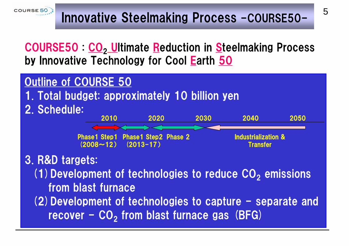
COURSE50 : CO2 Ultimate Reduction in Steelmaking Process by Innovative Technology for Cool Earth 50
• Coal is used to reduce iron ore in steelmaking process.• Even with enhanced energy-saving, emission of CO2 is unavoidable.
• COURSE 50 aims at developing technologies to decrease CO2 emissions by approximately 30% through reduction of iron ore by hydrogen as well as capture – separation and recovery – of CO2 from blast furnace gas.
• The initiative targets establishing the technologies by ca. 2030 with the final goal of industrializing and transferring them by 2050, taking advantage of renewing blast furnaces and relevant facilities.
Outline of COURSE 50
1. Total budget: approximately 10 billion yen
2. Schedule:
3. R&D targets:
(1)Development of technologies to reduce CO2 emissions
from blast furnace
(2)Development of technologies to capture - separate and
recover - CO2 from blast furnace gas (BFG)
Phase1 Step1(2008~12)
Phase1 Step2(2013-17)
Phase 2 Industrialization & Transfer
2010 2020 2030 2040 2050
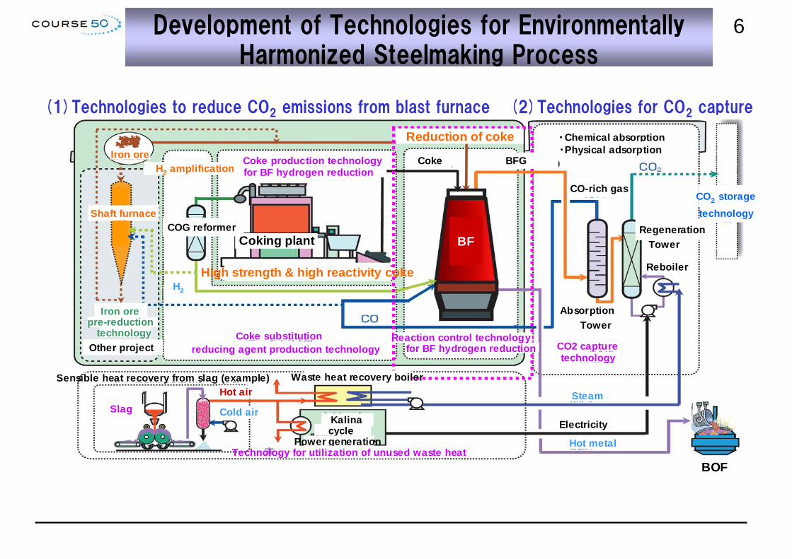
6Development of Technologies for Environmentally Harmonized Steelmaking Process
(1) Technologies to reduce CO2 emissions from blast furnace (2) Technologies for CO2 capture
・Chemical absorptionReduction of cokeIron ore
H2 amplification
H2
BOF
Electricity
High strength & high reactivity coke
Coking plant
Coke BFG
BF
Shaft furnace
・Physical adsorption
CO-rich gas
Regeneration Tower
Reboiler
Absorption Tower
Steam
Hot metal
Cold air
Hot air Sensible heat recovery from slag (example) Waste heat recovery boiler
CO2 storage technology
Kalina cycle
Power generation
Slag
Iron ore pre-reduction
technology Coke substitution reducing agent production technology CO2 capture
technology
Coke production technology for BF hydrogen reduction
for BF hydrogen reduction Reaction control technology
Technology for utilization of unused waste heat
Other project
COG reformer
(1)Technologies to reduce CO2 emissions from blast furnace (2)Technologies for CO2 capture
7Project Targets
(1)Development of technologies to reduce CO2 emissions from blast furnace
・ Develop technologies to control reactions for reducing iron ore with hydrogenous agents to decrease coke consumption in BF.
・ Develop technologies to reform coke oven gas (COG) aiming at amplifying hydrogen concentration by utilizing unused COG heat.
・ Develop technologies to produce high strength and high reactivity
coke for reduction with hydrogen.
(2)Development of technologies to capture - separate and recover - CO2 from blast furnace gas (BFG)
・ Develop techniques for chemical absorption and physical adsorption to capture CO2 from blast furnace gas.
・ Develop technologies to reduce energy to capture CO2 through enhanced utilization of unused waste heat.
8R&D Organization and Sub-Projects
1. Development of technologies to utilize hydrogen for iron ore reduction.2. Development of technologies to reform COG through the amplification of
hydrogen.3. Development of technologies to produce optimum coke for hydrogen
reduction of iron ore.4. Development of technologies to capture – separate and recover – CO2
from BFG.5. Development of technologies to recover unused sensible heat.6. Holistic evaluation of the total process.
* NEDO New Energy and industrial technology Development Organization ** COURSE 50 Committee at the Japan Iron and Steel Federation (JISF) supports the five companies’ R&D activities.
COURSE 50 Committee**
Sub-Projects (Phase1 Step1)
9Contents
1. About COURSE50 Project
2. Current status of COURSE50
3. Test operation trial at experimental blast furnace
10Sub-Project 1
Identification of feeding conditions of preheated gas, aiming at constraining ore degradation by reduction associated with enhanced reduction by hydrogen.
Pre-heated gas (N2, etc.) Gas Flow
Development of high strength coke with feeding of reformed COG (sub-project 3).
Evaluation of balances of energy and CO2 for an entire steelworks.
Reformed COG
・Clarification of optimal injecting conditions of reformed COG (RCOG).
・Model experiments
・Simulation
・Operation design model for RCOG usage based on the heat and mass balance model.
・Reviewing previous knowledge regarding blast furnace operations with high hydrogen reduction.
• Quantification of results of reduction in carbon supply.
・Quantification of improved reducibility of iron ore when feeding reformed COG.
・Evaluation of effects of accompanying reactions under hydrogen-co-existent gas conditions.
Combustion simulation of tuyere raceways under hydrogen co-existence.
Temperature Decrease
Sinter Degradation
Reduction Promotion
<<Technologies to utilize hydrogen for iron ore reduction>>
11Blast Furnace Inner Reaction Simulator
Characteristics of BIS furnace
・ Pseudo-counter flow moving bed ・ Possible to simulate endothermic
reaction associated with gasification and hydrogen reduction, as well as heat exchange.
Evaluation of reaction in blast furnace
[ Adiabatic ]
Coke
Coke
Sinter
Sinter Normal Coke C50% + Iron-coke C50%
Adiabatic control
Coke
Coke
Sinter
Sinter
Coke
Coke
Sinter
Sinter
Bosh gasExperiment under bosh gas conditions adjusted to hydrogensupply conditions
Heating at 100℃ to prevent condensation of water
12BIS Experimental Results on Iron Ore Reduction
40
50
60
70
80
0 5 10 15
水素還元率 (%)
~ 1050 ℃
300Nm3/thm
Reduction rate up to 1050℃
increases by feeding reformed COG
into the shaft.
Possibilities are :
1)indirect H2 reduction rate
increased,
2)direct reduction rate by water gas
reaction (C+H2O=CO+H2) increased.
Increase in indirect reduction
indicates the possibility of the effect
of H2 reduction.
Increment by indirect reduction
Increment by direct reduction
Slope assumed for simple hydrogen reduction with reformed COG injection
Experimental results with BIS
Reformed COG feeding rate Nm³/t-hm 0 200 300 Solution loss (up to 1050°C) kg/t-hm 54.5 69.9 83.2 Total reduction rate (up to 1050°C) % 49 63.7 72.8
•Possible to increase coke strength without relying on blending coking.
•Enhanced compatibility with raw materials at the time when hydrogen reduction is put in practical use.
・HPC starts softening and melting at low temperatures below 300 oC.・HPC packs coal particles effectively by filling gaps in between.=> It is possible to produce a high strength coke with HPC.
<<Technologies to produce optimum coke for hydrogen reduction of iron ore>>
17Enhancement of Coke Strength with HPC
● Experimental results(Base-1 blending)
HPC additionBase-1 blendingCoal packing density > 800kg/m3
84
86
88
90
700 750
DI
(
%)
150
15
800 850
Packing density (kg/m3, d.b.)
HPC 0%
HPC 5% addition
Base -1
D
C
B
A
Base-1
D
C
B
A
HPC 5% addition
Base-1 + HPC
C
B
(15%)
(26%)
(34%)
(25%)
(29%)
(26%)
(15%)
(25%)
Target coke strength :DI150
15≧88% achieved.
Strongly-caking coal
Semi coking coal
Non or slightly-caking coal
Base-1: Coking coal rich (normal)
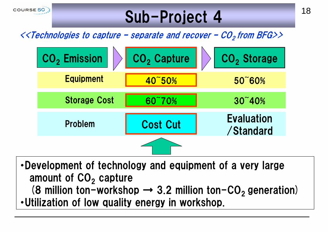
18Sub-Project 4
・Development of technology and equipment of a very large amount of CO2 capture (8 million ton-workshop → 3.2 million ton-CO2 generation)
・Utilization of low quality energy in workshop.
CO2 Emission CO2 Capture CO2 Storage
40~50% 50~60%
60~70% 30~40%
Cost CutEvaluation/Standard
Equipment
Storage Cost
Problem
<<Technologies to capture – separate and recover – CO2 from BFG>>
19Technical Subject of Chemical CO2 Capture
Relative Cost (%)
2.52.0
100
3.0
Recovery Heat of Chemical Absorbents (GJ/t-CO2)
Optimization of total process including steelmaking process
Increase in wasted heat usage
・High performance absorbent・Improvement of chemical absorption process
Conventional Method
Target of Development
Target Cost
90
80
70
60
50
40
30
20Collaboration Scheme to Develop New Chemical Absorbents
Development of new chemical absorbents
Quantum chemicalcalculations
Design new amine Compounds.
Synthesize new aminesDesign absorbentsEvaluate the performance
Suggest new amine compounds
ExperimentsChemoinformatics
Evaluation at Test Plants (NSSNG)
CAT1 (1t-CO2/d) CAT30 (30t-CO2/d)
Industrial application
StripperAbsorber
Reboiler
Evaluation of new absorbents Evaluation of chemical plant properties
Schedule:16th April ~11th May, 2012Schedule:16th April ~11th May, 2012
Blast Tuyere
Upper shaft Tuyere
Lower Shaft Tuyere
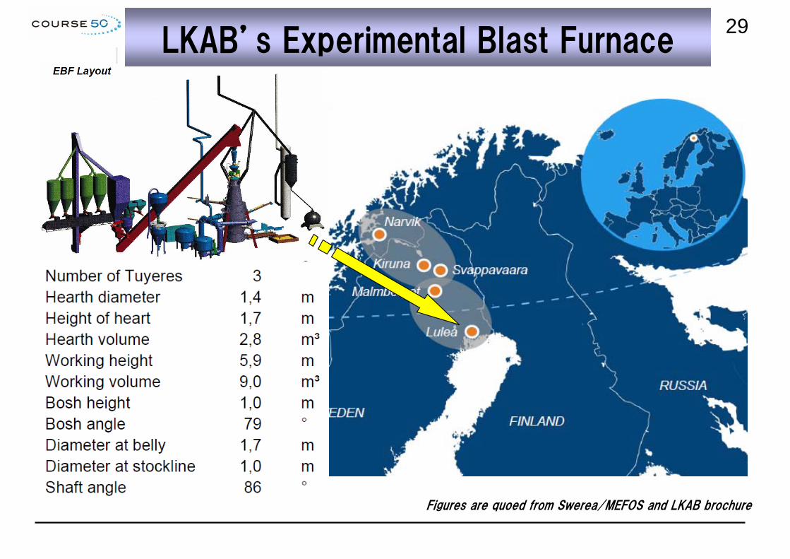
Figures are quoed from Swerea/MEFOS and LKAB brochure
31Operation Conditions (Gas Injection)
Synthetic COG and RCOG were mixed from pure gases to control constant and accurate gas composition through the trial operation for the main purpose of evaluating the effects of H2 reaction.
Synthetic COG and RCOG were mixed from pure gases to control constant and accurate gas composition through the trial operation for the main purpose of evaluating the effects of H2 reaction.
200Nm3/thm (300Nm3/h)
77.9%H2-10%CO-12.1%N2
(78ppmH2S)
Composition Injection Position Injection RateInjection
Temperature
COG57%H2+31.3%CH4+11.7
%N2
Blast Tuyers (3)100Nm3/thm (150Nm3/h)
RT
RCOG
77.9%H2-22.1%N2
Lower Shaft Tuyeres (3)
150Nm3/thm (225Nm3/h)
200Nm3/thm (300Nm3/h) 770℃
HTGCombusted BFG
(CO/(CO+CO2)>0.05)
Upper Shaft Tuyeres (3)
100Nm3/t 800℃
32RCOG Heating Apparatus
RCOG out(925℃)
Hot Gas in (1000℃)
Hot Gas out(824℃)
COG out(760℃)
Pre-Heater
EBF
Main-Heater
Tube Basket
Bustle Pipe
COG in(RT)
RCOG was heated up to 800°C through a counter-current heat exchanger and injected to EBF.
RCOG was heated up to 800°C through a counter-current heat exchanger and injected to EBF.
33RCOG Heating Apparatus
EBF
COG Heating App.
Lower Tuyere
RCOG Outlet
Pre-Heater
Main-Heater
34Hot Top Gas Injection Apparatus
Gas Cleaner
CompressorBFG
Oxygen and Nitrogen Supply
Top Gas
Oxygen Enriched Air+ Nitrogen
Upper Tuyeres
Burners
Figures are quoed from Swerea/MEFOS and LKAB brochure
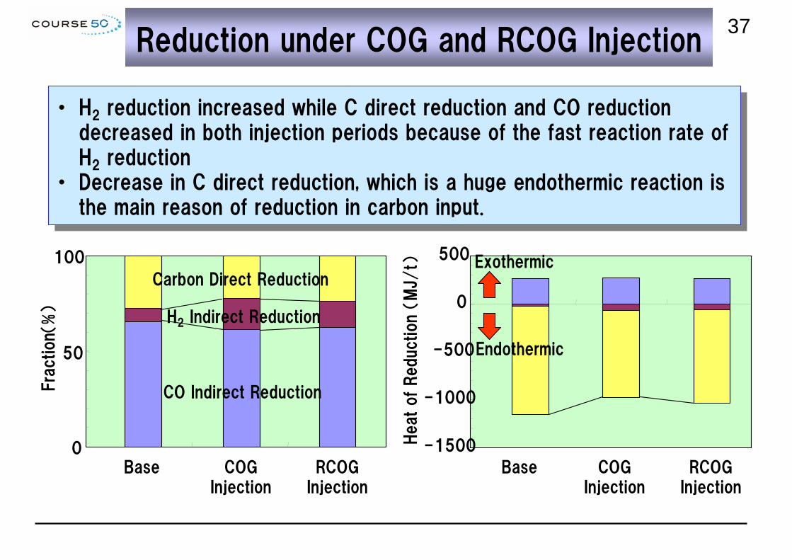
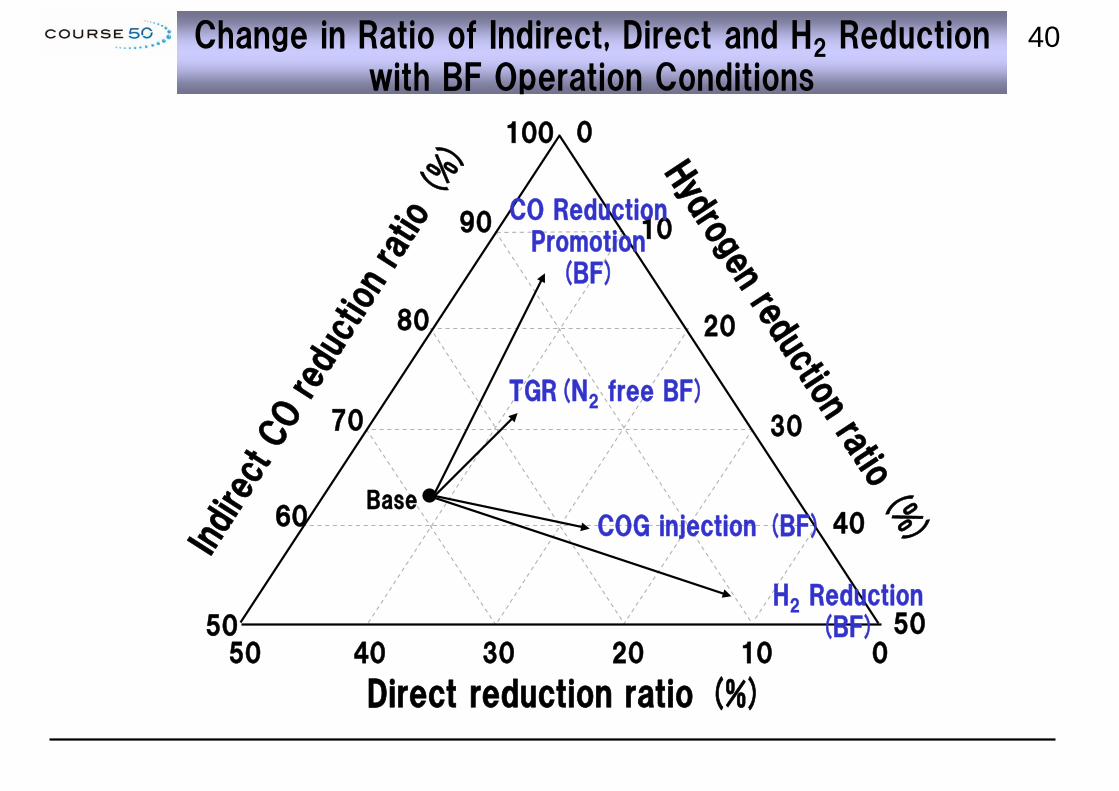
・ H2 reduction increased while C direct reduction and CO reduction decreased in both injection periods because of the fast reaction rate of H2 reduction
・ Decrease in C direct reduction, which is a huge endothermic reaction is the main reason of reduction in carbon input.
・ H2 reduction increased while C direct reduction and CO reduction decreased in both injection periods because of the fast reaction rate of H2 reduction
・ Decrease in C direct reduction, which is a huge endothermic reaction is the main reason of reduction in carbon input.
0
50
100
Base COGInjection
RCOGInjection
Fra
ction(%)
CO Indirect Reduction
H2 Indirect Reduction
Carbon Direct Reduction
-1500
-1000
-500
0
500
Heat of Reduction (
MJ/
t)
Base COGInjection
RCOGInjection
Exothermic
Endothermic
38H2 Concentration Distribution during COG/RCOG Injection
RCOG
COG
Lower Probe
・ Hydrogen concentration distribution during COG injection period was uniformly higher than the base period. => Gas from blast tuyere goes into the furnace through raceway
・ Hydrogen concentration only near the shaft tuyere was high duringRCOG injection period.=> Gas from shaft immediately reduces iron ore, small penetration depth
EBF figure iquoted from Swerea/MEFOS and LKAB brochure
RCOG
COG
39Vertical Distribution of Reduction Degree
0
50
100
2.0 3.0 4.0 5.0 6.0
Distance from Stock Level (m)
Reduction D
egre
e (
%)
Blast TuyereLower Shaft Tuyere
Reference (no injection)
This study (RCOG)
←furnace top
40Change in Ratio of Indirect, Direct and H2 Reduction with BF Operation Conditions
100
20
40
50
80
Indire
ct C
O red
uctio
n ra
tio (
%)
0
70
90 10
30
0102030
Direct reduction ratio (%)
Hydrogen reduction ratio (%
)
H2 Reduction (BF)
COG injection (BF)
TGR(N2 free BF)
CO ReductionPromotion
(BF)
60
504050
Base
41Effect of HTG Injection on Upper Part Temperature
Hot Top Gas (800℃)
Vertical Probe
COG Injection
Dis
tance fro
mSto
ck
Leve
l (m
)
-4.0
-3.0
-2.0
-1.0
0
400 600 800 1000 1200
Detected Temperature by Vertical Probe (℃)
Before HTG Injection
After HTG Injection
290
270
250
230
210
190
170
150
Top G
as
Tem
pera
ture
(℃
)
280
240
200
160
120
80
40
00 2 4 6 8 10
HTG Inje
ction V
olu
me
(Nm
3/th
m)
Time (hr)
EBF figure quoted from Swerea/MEFOS and LKAB brochure
HTG Started
42Change in Sinter Particle Fraction in Shaft
Base
RCOGInjection
RCOG Injection
COG Injection + HTG
RCOG Injection + HTG
COGInjection
-6.3mm fraction at Ore Bin-6.3mm fraction at Ore Bin
COGInjection
-5mm fraction (%)-5mm fraction (%)
Dis
tance fro
m S
tock
Leve
l (m
)
Dis
tance fro
m S
tock
Leve
l (m
)
43Summary
1) Improvement of the reduction of iron ore by hydrogen injection has been
verified by experimental BF test with hydrogen enriched reformed COG
shaft injection and COG injection from ordinary tuyere.
2) Bench scale test results of COG reforming technologies (hydrogen
enrichment) indicate the possibility of making hydrogen content double.
3) Technology of producing high-strength coke stably by adding HPC
(High Performance Caking additive) has been prospective.
4) The results of both chemical absorption and physical adsorption bench
scale test indicate the world’s lowest level of energy consumption to
capture CO2.
5) The results of studies on various promising waste heat recovery
technologies as well as an inventory of unused waste heat indicate the
possibility of satisfying the energy demand for CO2 capture.
Green electricity & Green hydrogen production technologies
CO2 Storage & Monitoring
COCS Project **(2001-2008)
JHFC Project *(2001-)
COG H2 enrichment Project
(2003-2006)
Partial substitution of carbon by hydrogen
CO2 capturefrom BFG
Hydrogen
Steelmaking
Intern’l collaboration
Development of fundamental technologies
Establishment of infrastructure
PhasePhaseⅠⅠ(Step 1)
Industrialization
PhasePhaseⅠⅠ(Step 2)
PhasePhaseⅡⅡ
Mini
exp. BF
EBF + PartiallyIndustrial
Matching between capture equipment and mini exp. BF
Integrated operation of semi-industrial capture equipment (several hundred t-CO2/D) with exp. BFULCOS (2004-)
1st industrialization by ca. 2030 <Prerequisite> CO2 storage available Economic reasonability
* Japan Hydrogen & Fuel Cell Demo. Project. * *Cost-saving CO2 Capture System
Verification
Hydrogen reduction
CO2 capture
Industrialization
Reduction fundamentalsOptimized gas injectionBench-scale H2
enrichment
Process evaluation plantTotal evaluation
incorporating mid - low temperature waste heat recovery
45
Acknowledgement
This study was carried out as a national project for development of technologies for environmentally harmonized steelmaking process, ‘COURSE50’supported by the New Energy and industrial Technology Development Organization (NEDO).


![Pseudo Limits, Biadjoints, and Pseudo Algebras: Categorical ...arXiv:math/0408298v4 [math.CT] 18 Oct 2006 Pseudo Limits, Biadjoints, and Pseudo Algebras: Categorical Foundations of](https://static.documents.pub/doc/80x56/60a7a6d20b1ec1029337c248/pseudo-limits-biadjoints-and-pseudo-algebras-categorical-arxivmath0408298v4.jpg)
