NTIA-REPORT-81-74 Recommendations for Digital Radio Common Tactical/Long-Haul Standards J.E. Farrow L.G. Hause u.s. DEPARTMENT OF COMMERCE Malcolm Baldrige, Secretary Dale N. Hatfield, Acting Assistant Secretary for Communications and Information May 1981
Transcript
NTIA-REPORT-81-74
Recommendations for Digital Radio
Common Tactical/Long-Haul Standards
J.E. FarrowL.G. Hause
u.s. DEPARTMENT OF COMMERCEMalcolm Baldrige, Secretary
1. DIGITAL RADIO ISSUES GERMANE TO A COMMONTACTICAL/LONG-HAUL SYSTEM STANDARD 11.1 Introduction to System Standards 11.2 Basic Issues 4
1.3 Recommendations for System Standards 162. RECOMMENDATIONS FOR DIGITAL RADIO LINK
SUBSYSTEM STANDARDS 172. 1 Introduction 172.2 Subsystem Standard Organization 192.3 A Critique of the Tropospheric Radio
Circuit Subsystem Standards 23
3. DIGITAL LOS MICROWAVE RADIO EQUIPMENTSTANDARDS UPGRADE RECOMMENDATIONS 283. 1 Introduction to Equipment Standards 28
3.2 Review Appropriate Documents 283.3 Aspects of Equipment Covered 29
3.4 Improved Design Parameters 30
3.5 Field Modification Upgrades 39
3.6 Specific Questions from Statement of Work 41
3.7 Conclusions and Recommendations forEquipment Standards 42
4. CONCLUSIONS 43
5. REFERENCES 44
APPENDIX 47
iii
1
1
1
1
1
1
1
1
1
11
1
1
1
1
1
1
1
1
1
1
1
1
1
1
1
1
1
1
1
1
RECOMMENDATIONS FOR DIGITAL RADIO COMMONTACTICAL/LONG-HAUL STANDARDS
J. E. Farrow and L. G. Hause*
This report is the sum of a three-part effort by the Institutefor Telecommunication Sciences (ITS) to provide technical recommendations for the DCS Long-Haul Tactical Common system, subsystem,and equipment technical standards for digital radio. The work wassponsored by the Defense Communications Engineering Center,Reston, VA.
Primary recommendations for the system standards include suggested reference circuit and channel distances within a common overseas DCS terrestrial segment; the suggestion that only digitalsubsystems be included in the global reference circuit; and thestatement that only parameters directly measurable in digital systems(such as bit-error-rate) be used in defining performance. Themain recommendations for subsystems standards include a recommendedscope for subsystem standards; suggestions for specific content inwhich appropriate standards and subsystem parameters are identified;and exclusion of all reference to FDM/FM parameters from new drafts.Some important guidelines for the equipment standards include anoutline for the equipment standards; recommendations on the realismand practicality of design parameters; and recommendations onpossible techniques to be included in the standard for upgradingexisting facilities.
Key words: digital microwave; equipment standard; radio system standard;subsystem standards; tactical communication
*The authors are with the Institute for Telecommunication Sciences,National Telecommunications and lnformation Administration,U.S. Department of Commerce, Boulder, CO 80303.
1. DIGITAL RADIO ISSUES GERMANE TO A COMMONTACTICAL/LONG-HAUL SYSTEM STANDARD
1.1 Introduction to System Standards
1.1.1 Purpose of the Common System StandardThe purpose of developing a military communication system technical standard
common to both long-haul and tactical applications, besides the usual purposes ofa system standard, is to improve interoperation of long-haul and tactical communication systems of the Department of Defense as agreed to by USAEC and DCA in amemorandum of understanding.
Some of the usual purposes of communication system standards are to providethe following types of information:
1. Channel characteristics for the establishment of interconnectingcircuits between users. (See MIL-STD-188-100, 15 Nov. 1972, page 1.)
2. User-to-user requirements and hypothetical reference circuitswhich are essential for developing overall system plans andsubsystem standards. (See MIL-STD-188-100, 15 Nov. 1972, page9; and Draft MIL-STD-188-200, 1 June 1978, page 3.) These requirementsinclude adequate quality and availability of service values.
3. Performance parameters, definitions, and values without specifying thetechnology that is used to obtain the required performance. (See DraftMIL-STD-188-200, 1 June 1978, page 4.)
4. Requirements for commonality of equipment and reasons to discourageproliferation of equipment types serving the same or similar function.(See Draft MIL-STD-188-200, page 4.)
The purpose of this report is to examine issues germane to the digital radioportions of the military communication system technical standard common to bothlong-haul and tactical applications (hereafter referred to as the common systemstandard).
1.1.2. Scope of ReportThe three-part effort to provide technical recommendations for the DCS Long-Haul
Tactical Common standards was done in three major subtasks corresponding to system,subsystem, and equipment standards. The three major subsections of this report correspond to the three subtasks. This work was sponsored by the Defense CommunicationsAgency, Defense Communications Engineering Center, 1860 Wiehle Avenue, Reston, VA
22090. The subtask one section covers the digital radio aspects of the commonsystem standard. The range of radio system issues covered by this report arethose which lie in the following categories:
a. Radio system transmission bit rates.b. LOS microwave system carrier frequencies.c. Beyond-the-horizon, "Tropo" system carrier frequencies.
d. Type IV tactical systems (less maneuverable) as described inMIL-STD-188-200 (1978).
The tactical/long haul interface is a hierarchy/multiplex issue and notprimarily a radio issue. The level of hierarchy at which the interface occursdoes affect radio equipment so this issue is discussed briefly but no recommendations are made.
1.1.3 ApproachThe general approach to the problem of improving and encouraging the inter~
operability of long-haul and tactical digital communication systems has been todefine a reference circuit which approximates a typical connection which could bemade through the total communication system. Such reference circuits, which havebeen very important elements in all standards to date, provide a convenienttechnique for allocating particular technical requirements to each of the subsystems which support the reference circuit.
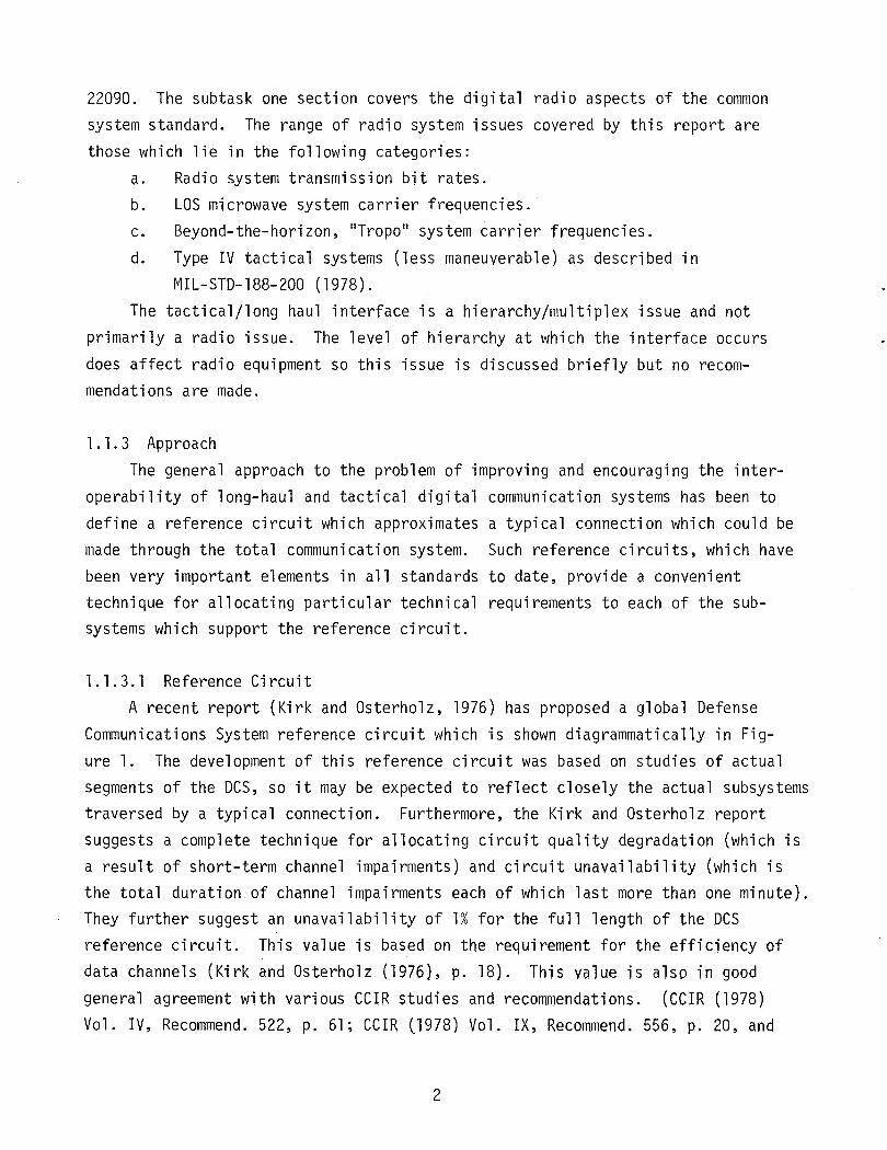
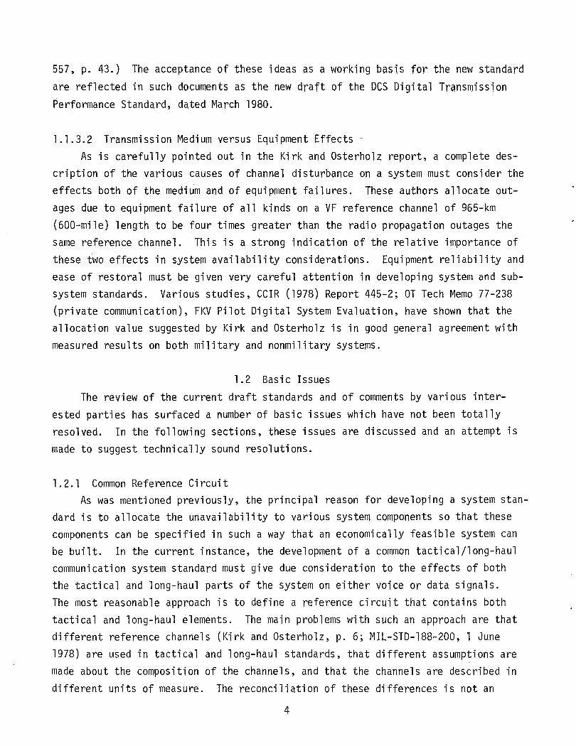
1.1.3.1 Reference CircuitA recent report (Kirk and Osterholz, 1976) has proposed a global Defense
Communications System reference circuit which is shown diagrammatically in Fig-ure 1. The development of this reference circuit was based on studies of actualsegments of the DCS, so it may be expected to reflect closely the actual subsystemstraversed by a typical connection. Furthermore, the Kirk and Osterholz reportsuggests a complete technique for allocating circuit quality degradation (which isa result of short-term channel impairments) and circuit unavailability (which isthe total duration of channel impairments each of which last more than one minute).They further suggest an unavailability of 1% for the full length of the DCSreference circuit. This value is based on the requirement for the efficiency ofdata channels (Kirk and Osterholz (1976), p. 18). This value is also in goodgeneral agreement with various CCIR studies and recommendations. (CCIR (1978)Vol. IV, Recommend. 522, p. 61; CCIR (1978) Vol. IX, Recommend. 556, p. 20, and
4 VF Channels I I. 4 VF Channels ----1>00 till"j VF Reference... 2~OO t1fles~ 240Q fine'" .. Channel
a. Global DCS Reference Circuit
C!.Gtl R GC
Q---o----o- . I I I TROPO ~I '0 tI, 1" -..; LOS1--' 100 till" I14 LOS &1 TRapa
• 600 tlfles ..
b. DCS VF Reference channel
C~Gtl--Chilnnel and Group tlultiplexGC----Group ConnectR-----Rp.pealer
Figure 1. DCS reference configurations (from draft MIL STD 188-XXX, March 1980).
557, p. 43.) The acceptance of these ideas as a working basis for the new standard
are reflected in such documents as the new draft of the DeS Digital TransmissionPerformance Standard, dated March 1980.
1.1.3.2 Transmission Medium versus Equipment Effects ~
As is carefully pointed out in the Kirk and Osterholz report, a complete description of the various causes of channel disturbance on a system must consider theeffects both of the medium and of equipment failures. These authors allocate outages due to equipment failure of all kinds on a VF reference channel of 965-km(600-mile) length to be four times greater than the radio propagation outages thesame reference channel. This is a strong indication of the relative importance ofthese two effects in system availability considerations. Equipment reliability andease of restoral must be given very careful attention in developing system and subsystem standards. Various studies, CCIR (1978) Report 445-2; OT Tech Memo 77-238(private communication), FKV Pilot Digital System Evaluation, have shown that theallocation value suggested by Kirk and Osterholz is in good general agreement withmeasured results on both military and nonmilitary systems.
1.2 Basic IssuesThe review of the current draft standards and of comments by various inter
ested parties has surfaced a number of basic issues which have not been totallyresolved. In the following sections, these issues are discussed and an attempt ismade to suggest technically sound resolutions.
1.2.1 Common Reference CircuitAs was mentioned previously, the principal reason for developing a system stan
dard is to allocate the unavailability to various system components so that thesecomponents can be specified in such a way that an economically feasible system canbe built. In the current instance, the development of a common tactical/long-haulcommunication system standard must give due consideration to the effects of boththe tactical and long-haul parts of the system on either voice or data signals.The most reasonable approach is to define a reference circuit that contains bothtactical and long-haul elements. The main problems with such an approach are thatdifferent reference channels (Kirk and Osterholz, p. 6; MIL-STD-188-200, 1 June1978) are used in tactical and long-haul standards, that different assumptions aremade about the composition of the channels, and that the channels are described indifferent units of measure. The reconciliation of these differences is not an
4
impossible task but it will require some adjustment of both tactical and long-haulstandards and ways of thinking.
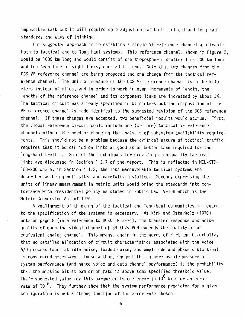
Our suggested approach is to establish a single VF reference channel applicableboth to tactical and to long-haul systems. This reference channel, shown in Figure 2,would be 1000 km long and would consist of one tropospheric scatter link 300 km longand fourteen line-of-sight links, each 50 km long. Note that two changes from theDCS VF reference channel are being proposed and one change from the tactical reference channel. The unit of measure of the DCS VF reference channel is to be kilometers instead of miles, and in order to work in even increments of length, thelengths of the reference channel and its component links are increased by about 3%.The tactical circuit was already specified in kilometers but the composition of theVF reference channel is made identical to the suggested revision of the DCS referencechannel. If these changes are accepted, two beneficial results would accrue. First,the global reference circuit could include one (or more) tactical VF referencechannels without the need of changing the analysis of subsystem availability requirements. This should not be a problem because the critical nature of tactical trafficrequires that it be carried on links as good as or better than required for thelong-haul traffic. Some of the techniques for providing high-quality tacticallinks are discussed in Section 1.2.7 of the report. This is reflected in MIL-STD188-200 where, in Section 4.1.2, the less maneuverable tactical systems aredescribed as being well sited and carefully installed. Second, expressing theunits of linear measurement in metric units would bring the standards into conformance with Presidential policy as stated in Public Law 19-168 which is theMetric Conversion Act of 1975.
A realignment of thinking of the tactical and long-haul communities in regardto the specification of the systems is necessary. As Kirk and Osterholz (1976)note on page 8 (in a reference to DCEC TR 3-74), the transfer response and noisequality of each individual channel of 64 kb/s PCM exceeds the quality of anequivalent analog channel. This means, again in the words of Kirk and Osterholtz,that no detailed allocation of circuit characteristics associated with the voiceAID process (such as idle noise, loaded noise, and amplitude and phase distortion)is considered necessary. These authors suggest that a more usable measure ofsystem performance (and hence voice and data channel performance) is the probab i 1itythat the mission bit stream error rate is above some specified threshold value.Their suggested value for this parameter is one error in 106 bits or an errorrate of 10-6. They further show that the system performance predicted for a given
configuration is not a strong function of the error rate chosen.
ct.Gll R GCr ~ -----l LOSI-- ~ ~ J300KM• 14 LOS & 1 TROPO 50~ ~
I(JOO krn
b. DCS VF Reference channel
C.r.Gll--Channel and Group IlultiplexGC----Group ConnectR-----Rp.peater
Figure 2. Suggested combined tactical/long-haul reference circuit and channel.
To summarize the foregoing discussion, we recommend that a common tactical/
long-haul digital VF reference channel be adopted and that it be as illustrated inFigure 2. We recommend that for the all-digital global combined reference circuit,no detailed allocation of voice circuit characteristics associated with the voiceA/D and D/A process be considered. We recommend that the performance of the radiolinks which support the reference channel be described in terms of the probabilitythat the bit error rate is above a threshold value as suggested in Kirk andOsterholz (1976).
1.2.2 Mixed Analog-Digital Reference CircuitIn establishing a reference circuit for the combined tactical/long-haul stan
ard, a basic issue which remains unresolved is whether to permit analog radio linksto be part of the DCS global reference circuit. In favor of this idea is theimportant cons i derati on that much of the Defense Communi cati on System wi 11 be composed largely of analog radio links for several more years at least, and may haveanalog radio links in some places far into the future. Thus a reference circuitwhich includes both analog and digital transmission subsystems would be a moreaccurate reflection of the current situation. The rapid pace of replacement ofanalog radio links by digital ones decreases the strength of this argument, however.
The most important reason for not considering a hybrid reference circuit isthat these circuits are affected differently by transmission impairments. Thisdifference is clearly pointed out in the Kirk and Osterholz report on page 2, andis reflected in the description in CCIR (1978), Recommendation 556 of an all digital reference circuit. We recommend that a digital-only combined global referencecircuit be established.
1.2.3 Combined Global Reference Circuit QualityAs was previously cited in this report, Kirk and Osterholz (1976) consider the
quality of a voice channel in terms of the probability of short duration disturbances occurring during a 5-minute telephone conversation. The approach theseauthors took in their analysis involved examining the probability that any of theradio links making up the reference circuit would fade deeply enough to cause anerror burst in the digital baseband data stream. Although Kirk and Osterholz havedone a much more detailed analys is of reference channel quality than has beenreferenced in the CCrR documents, their approach is quite similar to that outlinedin CCIR (1978) Report 378-3 in which the channel disturbances are characterized ashigh error rate (fairly long) periods and short error bursts. The CerR (1978)
7
report further discusses the duration and severity of error bursts with reference
to the probability of call dropout due to the effects of error bursts on automatic
switching systems. While Kirk and Os te rholz have considered the effects of customer patience instead of automatic switching systems on the likelihood of callabandonment or dropout, their analysis may more closely reflect the conditions tobe found on the DCS or on tactical systems. For this reason, we recommend that theKirk and Osterholz approach be used while bearing in mind that on page 19 of TR12-76, the authors encourage further study of the precise numerical values to beused in describing channel quality. It is interesting to note that the CCIR (1978)report referenced above makes a similar recommendation.
1.2.4 Combined Global Reference Circuit AvailabilityOne of the most important aspects of system operation is the availability of ser
vice. This importance is reflected in various CCIR Reports and Recommendations forcivilian systems; for military command and control systems, the availability is ofcritical importance. Kirk and Osterholz have proposed a value of 0.99 for end-to-end reference circuit availability and have considered the factors affecting availability. Their analysis allocates an unavailability of 0.004 for the overseasterrestrial segment (see Figure 2.) which is in very good general agreement withmeasured values of circuit availability given in CCIR (1978) Report 445-2. Werecommend that the values of allocated unavailability suggested by Kirk and Osterholz be retained as working standards until experience provides an even betterbasis for selecting these numerical values.
1.2.5 Inclusion of Multichannel Radio Links OnlyThe development of a common tactical/long-haul reference circuit must be pre
ceded by a decision as to what sorts of equipment will be considered suitable tosupport the reference circuit. A first part of this decision would be to includeonly equipment which carries interswitch trunks. The reason for doing this wouldbe to exclude single-channel or small-capacity radio links which will likely carrydedicated circuits. These narrowband radios should be considered part of thesubscriber loop and beyond the scope of the reference circuit standard. Otherconsiderations are that single-channel radio links are highly mobile, and theiroperating frequency is outside of the range of consideration as stated in Section1.2.7. For these reasons, we recommend that only radio links whose mission bitstream is at a rate equal to or greater than that output by the first level
multiplex be considered as supporting the combined global reference circuit.
8
1.2.6 Equipment Reliability ConsiderationsIn discussing the availability of the reference circuit, Kirk and Osterholz
allocate one-fifth of the outage time on the overseas segment to propagation problemsand four-fifths of the outage time to equipment failure outages. This proportionindicates that efforts to improve subsystem availability will payoff four to one ifthe effort is made to improve equipment reliability rather than propagation reliability. This should not be taken to imply that efforts to improve radio propagation reliability are not valuable but rather to indicate that there is a much moreuseful and cost effective effort to be made in a currently neglected area.
At this point, we disagree with Kirk and Osterholz on system reliability. Onpage 25, these authors state:
liThe major factors whi ch affect equi pment-rel ated unavail abil ity are (1) thedegree of equipment redundancy in the system, (2) the efficiency of performancemonitoring techniques to detect and switch to standby equipment when failuresoccur, and (3) the logistics approach that is used to effect the restoral offailed equipments. Of these factors, the most important is the degree of redundancy. Effectively used redundancy allows nearly uninterrupted service whena single equipment fails.
The next most important factor in optimizing availability is the selectedlogistics approach. An adequate supply of spare modules or assemblies must beavailable on-site to avoid excessive downtime after a failure occurs. Also,personnel must be available to make the corrective action. Also, travel time isa very important factor in determining the mean-time-to-service-restoral (MTSR).(Note the difference between MTTR which addresses only the time required torepair a unit, given that both personnel and parts are available, and MTSRwhich includes travel time and time to locate the appropriate part, plus thebasic MTTR.)
The third major factor affecting unavailability is performance monitoringeffectiveness. Performance monitors must be capable of detecting the failure ofon-line redundant units and switching to the off-line unit but, even more importantly, they must be capable of detecting failures in an off-line unit so thatit can be repaired before it is needed. Inability to detect an on-line equipmentfailure can be rectified by manually activated switchover to a standby equipment(hence a very short time-to-restore) when the on-line unit subsequently fails.This occurence results in the need.t~dispatch a maintenance man to physicallyrepair the equipment before service is restored.
The above factors result in equipment-related availability being describedin terms of four parameters:
(1) the mean-time-between-outages (MTBO) which can be restored by manualredundancy switching,
(2) the mean-time-between-outages (MTBO) which require equipment repair toaccomplish service,
9
(3) the mean time-to-service-restoral (MTSR) when an operational redundantunit is available, and
(4) the mean-time-to-service-restoral (MTSR) when actual equipment repairis requi red.
Of the above four factors, (3) can be assumed to be trivial relative to (4), andhence (1) is also trivial. In summary, the major factors which affect theunavailability of a system such as the DCS which widely uses redundancy are thepercentage of undetected off-l ine equi pment fail ures whi ch null ify the advantageof redundancy, the manning density of the maintenance function which determinesthe travel time component of MTSR, and the adequacy of spare parts support."
While such an analysis can be expressed in a closed mathematical form, itignores the realities of life on the DCS. It is not in agreement with the analysesgiven in CCIR (1978), Report 445-2, which shows five outage types. These categories are equipment failure, propagation, loss of primary power, maintenance,human error, and all other occurrences for which no cause could be isolated. Theauthors' personal experiences are that equipment failures are not independentrandom events but, rather, they tend to cluster. This clustering is usually dueto human factors which are not considered in the foregoing analysis. For instance,if a technician attempts to restore to service some equipment with which he isunfamiliar, there is a great likelihood that he will do more harm than good. Thisis not an unknown occurrence to the authors· certain knowledge. This is discussedin FKV Pilot Digital System Evaluation, Volume 1, page 4 (private communication).
A second serious flaw in the Kirk and Osterholz analysis ignores design andinstallation errors which cause clustered outages. Such things as antennas fallingoff towers, waveguide systems which must be repeatedly replaced, and power distribution systems that pull a site down when the operator attempts to switch fromcommercial to stand-by power contribute a major portion of system unavailability.Furthermore, the time to restore a failed antenna system for instance can be aslong as 6 months.
These remarks are intended to convey a sense of urgency regarding the contribution of equipment failure to reference circuit unavailability and to inject anote of reality into the calculation of unavailability related to equipmentfailure. Serious engineering design flaws and installation errors are both due tohuman factors which need to be controlled. The statement in the last line fromthe Kirk and Osterholz quote concerning lithe manning density of the maintenance
functi on" demands correcti on to lithe ski 11 dens ity of the maintenance functi on II •
10
It is a total fallacy to assume that all military personnel of a certain MilitaryOccupational Specialty (MOS) will have the same level of training, native intelligence, motor skills, or motivation, and any analysis based on such an assumption
will provide very little guidance for system improvement. It is further a misuseof reliability analysis to ignore the most important contributor to the unreliability of the DCS, namely the human factor. In this same vein, another aspect ofthe human-factor problem must be mentioned, namely the system management function.Even the most elaborate scheme of fault detection and reporting which could bedevised is worthless unless human operators respond to the information provided.It is a management function to ensure that the fault-detection information reachesthe right people, that the proper interpretation of the information is made, thatappropriate corrective action is undertaken in a timely manner and that follow-upinsures that correction is made. Management must respond to the failure of anyoneof these activities with improved training, improved motivation, or improvedoperating procedures. This is the only way to reduce system unavailability toprojected levels. Management must also support their lower echelon maintenancepersonnel to the extent that if a problem keeps recurring, higher level maintenance efforts can be promptly called upon to correct the equipment problem.
The authors are of two minds on including this material in this report. Thereference circuit is an intellectual tool to be used as an aid in system conception, design, and implementation, while this diatribe on reliability relates tothe lowest level of the physical equipment and operation. However, if the reference circuit standard does not reflect fairly closely the actual conditions on thesubsystems which will carry the reference circuit, then its development becomes asterile mental exercise which will in no way contribute to improved communicationservice for DCS customers. It is recommended that the assumptions made aboutsystem management and skill levels required to validate the use of the referencecircuit be stated clearly and explicitly in the documentation describing theglobal reference circuit.
1.2.7 Range of Major Radio Types to be Covered by the StandardImportant among the issues are the ranges of digital radio types which
should be covered by the standard for the common system. As an example, radiosystems using carrier frequencies below 0.3 GHz should not be covered becausethese bands do not have the required capacity due to crowded spectrum conditions
and many are primarilY designated for other services by international agreement.
11
The ranges of digital radio types that are within the scope of the commonsystem standard are defined by:
a. Carrier frequency rangeb. Radio transmission bit rate rangec. Path types which are line of sight (LOS) and beyond the horizon (Tropo).The carrier frequency range for LOS paths is from 0.4 GHz to about 9.0 GHz.
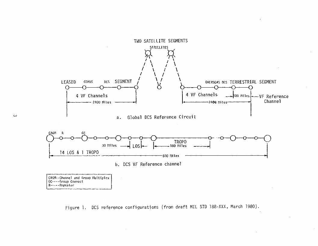
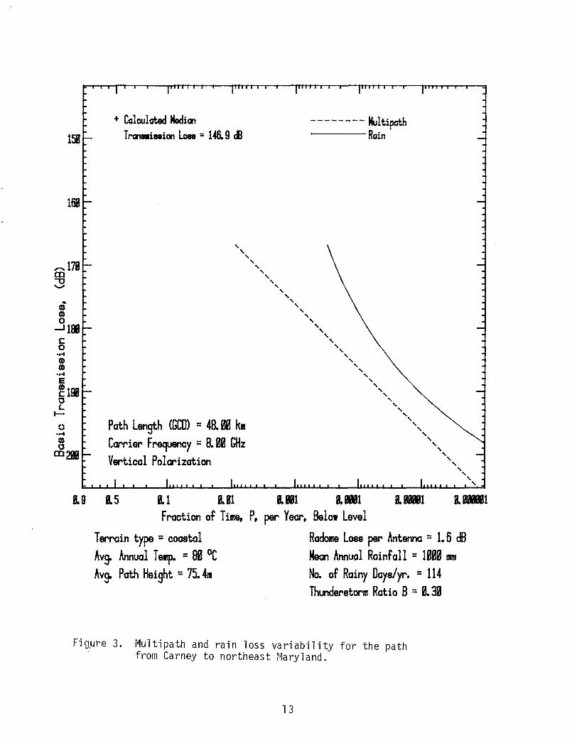
The upper end of the 7.125 - 8.400 GHz band should be the upper frequency limitbecause the major cause of channel outage changes from multi path outage to rainattenuation effects fairly rapidly within the 7.1-8.4 GHz band. This is shown byexamples of theoretical calculations for a 48-km path in Maryland (Figures 3 and4). The 15 GHz band was selected for the example in Figure 4 because this band isthe next available Government band above 8.4 GHz. The system standards for bothtactical and long-haul links operating at frequencies above 8.4 GHz will requirespecial attention to the rain attenuation effect. The calculation results shownhere were obtained from the models in Hause and Wortendyke (1979) pages 33-50.
At 8 and 15 GHz, the multipath predictions are the same because the multipathoccurrence factor is greater than 1. For severe multipath fading, a Rayleighdistribution through the long-term median does, indeed, seem to be close to thelimiting case. An example of such data is shown in Hause and Wortendyke (1979),page 35.
At 8 GHz, rain-attenuation and multipath outage time are about equal for this48-km path when diversity improvement is considered. At 15 GHz, rain attenuationis seen to dominate the outage statistics totally, at least for this path inMaryland.
The range of carrier frequencies for tropo paths has been well establishedand should not be at issue. This range is 0.4 to 5 GHz (draft MIL-STD-188-XXX,March 1980). Carrier frequency ranges should be the same for both tactical andlong-haul system standards because the equipment state-of-the-art and propagationlimitations are approximately the same for both kinds of systems.
Limitations on the upper and lower radio transmission bit rates for systemscovered by the common system standard are determined by the multiplex hierarchy onthe low end (1.5 Mb/s) and the multipath caused distortion on the upper end.
The maximum bit rate covered in the common system standard should be nominally 50 Mb/s based on hierarchy requirements and the finding that, up to the 50 Mb/srange, digital microwave links are not sensitive to frequency selective fading
Radome Loss per Antenna =1. 6 dBMean Annual Rainfall = 1& mmNo. of Rainy Days/yr. = 114Thunderstorm Ratio 8 =ill
Multipath and rain loss variability for the pathfrom Carney to northeast Maryland.
13
Technical Concepts of Access Area Mapping and Gateway Interfacing of DigitalCommunication Systems, pp. 46-59}, the only rate which the tactical and long-haulsystems have in common is 1.544 Mb/s, so that careful consideration should begiven to interfacing at this data rate. We have not considered the problems ofvoice channel digitizing rate or format changes. If equipment designed to changechannel rates and formats between tactical and long-haul hierarchies becomeswidely available, then interoperability would be greatly faci1itiated even to theex~ent that tactical and long-haul radio links could be interspersed to supportthe reference channel. ITS offers no recommendation on this matter.
1.3 Recommendations for System StandardsThis section of the report contains a list of all recommendations made in the
various preceding sections. The recommendation number corresponds to the subparagraph number where the issues are discussed in Section 1.2.
lao It is recommended that a common tactical/long haul digital VF referencechannel be adopted and that it be as illustrated in Figure 2 of thisreport.
lb. It is recommended that for the all-digital global combined referencecircuit, no detailed allocation of voice circuit characteristics associated with the voice A/D and D/A process be considered.
lc. It is recommended that the performance of the radio links which supportthe reference channel be described in terms of the probability that thebit error rate is above a threshold value as suggested in DCEC TR 12-76.
2. It is recommended that a digital-only combined global reference circuitbe established.
3. It is recommended that the Kirk and Osterholz approach (to describingcombined global reference circuit quality) be used while bearing in mindthat on p. 19 of TR 12-76, the authors encourage further study of theprecise numerical values to be used in describing channel quality.
4. It is recommended that the values of allocated unavailability suggestedby Kirk and Osterholz be retained as working standards until experienceprovides an even better basis for selecting these numerical values.
5. It is recommended that only radio links whose mission bit stream is at arate equal to or higher than the output of the first level multiplex beconsidered as supporting the combined global reference circuit.
16
6. It is recommended that the assumptions made about system management and
skill levels required to validate the use of the combined global refer
ence circuit be clearly and explicitly stated in the documentation describing the reference circuit.
7. It is recommended that the global reference circuit system standardscover only terrestrial radio equipment of the following characteristics:Line-of-sight radio sets with a carrier frequency between 0.4 and 9 GHzwith a mission bit stream capability of 1.5 to 50 Mb/s and troposphericscatter radio sets with a carrier frequency of 0.3 to 5 GHz and a missionbit stream capability of 1.5 to 12.5 Mb/s.
8. It is recommended that the 1972 edition of MIL STD 188-100 be retainedas a standard for analog systems.
9. ITS offers no recommendation on the matter of the location in the multiplex hierarchy of the long-haul/tactical interface.
2. RECOMMENDATIONS FOR DIGITAL RADIO LINK SUBSYSTEM STANDARDS
2.1 IntroductionThis report on subtask 2 will concern itself with a review of the common
tactical/long-haul line-of-sight subsystem design standard, MIL STD 188-145 DRAFT24 April 1977, and the common long-haul tactical troposcatter subsystem designstandard, MIL STD 188-144 DRAFT January 1980. There is no draft of MIL STD 188141 on high-frequency digital subsystems available so the contribution to thissubject will be to discuss the key subsystem parameters in Sections 2.1 and 2.2of this section which apply generally to all modes of propagation.
2.1.1 Basic ConceptWhile reviewing the two available subsystem standards, it was observed that
the purpose of both documents is 11••• to provide technical standards for(tropospheric scatter or microwave) radio links ... 11 and that the documents are11••• to be used in the design and engineering of new (tropospheric scatter ormicrowave) communication links .... 11 The emphasis in the subsystem standardsis on the establishment and continuity of radio communication which will meet thequality requirements of the global circuit standards and will make use of hardwarewhich meets the equipment technical standards. Thus, the subsystem design standards should describe the methods of us'ing standard hardware and should provide a
17
common ground between the global circuit requirements and the characteristics ofstandard equipment. The primary concerns of the subsystem standards should befactors affecting link performance. These are first, radio propagation effects, andsecond, radio-site infrastructure and support facilities.
A discussion and development of these two topics will form the major part ofthis report.
2.1.2 Limitations of Subsystem StandardsSubsystem standards are intended to fill the gap between equipment and global
circuit standards and must meet each of these other standards at their interfaces.Some of the material in the global circuit standard will need to appear in thesubsystem standard as will some equipment characteristics and parameters, but thesubsystem standard should not contain any detailed discussion or consideration ofthese other subjects. For instance, a simplified block diagram of a radio terminalmay be included to clarify a point, but no detailed equipment descriptions orstandards should be included nor should any operating parameters or circuit details.These topics must be covered in the equipment standards and may be included byreference, but they should not be repeated in the subsystem standard. Similarly,the subsystem standard may include a brief statement of global standard performancegoals and the maximum degradation of service to be permitted in each part of theglobal circuit but lengthy descriptions of global circuit quality and the rationalefor the development of such standards should be completely avoided although, again,they could be included by reference. Specific recommendations of sections of thedraft subsystem standards to be eliminated will be made in later sections.
To summarize, we recommend that the global digital reference circuit standardand the digital equipment technical standards be accepted as having been establishedin the preparation of the subsystem standards and that the subsystem standardsconcentrate on radio link propagation effects and radio site infrastructure andsupport facilities. Each of these areas will be dealt with in subsequent sectionsof this report.
We further recommend that the required single radio link availability derivedfrom the global circuit quality standard be set forth explicitly and that theaccompanying paragraphs state explicitly what causes of unavailability are to be
included in the figure. The possible causes of unavailability as considered
by Kirk and Osterholz (1976) are related to propagation and equipment failure
18
(TR 12-76, pp. 24 and 25), and the explanatory paragraph must show what fraction ofthe allowed unavailability will be properlY charged to each cause.
2.2 Subsystem Standard OrganizationThe subsystem standard should be organized to define and establish standards
for those parameters of particular importance to radio link performance. These werepreviously stated as:
1. Radio propagation effects, and2. Radio site infrastructure and support facilities.
2.2.1 Radio Propagation EffectsThe three modes of electromagnetic communication being considered here occupy
different frequency ranges, exploit different basic physical phenomena for theiroperation, and consequently are subject to interruptions from completely differentcauses. For instance, rain attenuation and atmospheric refractivity are the basicprocesses which limit line-of-sight propagation but they have no noticeable effecton HF links. Conversely, the state of the ionosphere is responsible for HF propagation while it has no influence on line-of-sight links. Tropospheric scatterpropagation on the other hand is affected by conditions both in the lower atmosphereand, at the lower end of the band, in the ionosphere. Nevertheless, the requirements of traffic sent via any of these propagation modes is described in the sameterms, namely, the quality and availability of the communication channel. Theglobal reference circuit is used to allocate unavailability among the componentlinks which make it up and the equipment standards give performance parameters whichare to be used to meet the availability requirements. The subsystem standardsshould direct the selection of appropriate equipment to provide communicationservice of the desired quality in the most economical way.
2.2.1.1 Basic Transmission LossOne of the most important concepts developed which permits an engineering
estimate of radio link performance to be made is that of basic transmission loss.Basic transmission loss is defined as 10 times the logarithm to the base 10 of theratio of the power fed directly to a loss-free isotropic antenna (located where theoperating antenna will be placed) to the power received at the terminals of aloss-free isotropic antenna at the distant terminal (again located at the
19
position of the operating antenna). Thus, basic transmission loss, Lb can be
expressed as
PtL - 10 log -b - Pr
The value of this concept is that it allows the radio path loss to be calculatedwithout reference to such variable factors as antenna gain, transmission lineloss, or absolute power levels involved. In fact, this concept is applicable toany frequency range or mode of transmission.
The signal received over any radio path will vary in time and usually overa very wide range. The prediction techniques which permit estimates of the timedistribution of transmission loss (and hence received signal level) are quitedifferent for each of the three modes of transmission discussed, and this leadsnaturally to having a separate standard for each propagation mode. We recommendthat the digital subsystem standard establish the propagation models to be employedin designing radio links, and establish the format in which the results of thecalculations are to be presented and used to determine the necessary equipmentoperating parameters (such as transmitter power, receiver sensitivity, and antenna si ze).
2.2.1.2 Path Clearance CriteriaOne of the most important ideas with regard to the operating parameters of a
tropospheric communication circuit (that is, line-of-sight or troposcatter) isthe necessity of determining what mode of propagation any particular radio linkwill operate in. This is primarily a function of the radio path terrain clearancewhich is in turn influenced by local climatic conditions. The reason for theimportance attached to this decision is that a normally line-of-sight link whichoperates in a diffraction or troposcatter mode for any perceptible fraction ofthe time will not be able to meet the availability requirements derived from theglobal reference circuit. Recall that this derived unavailability for a microwavepath is about 2.6 minutes per year so that the fraction of time per year that apath is obstructed must be considerably shorter than this for a radio link to beconsidered line of sight. Recent work on the amount of clearance required has
prOVided values based on measured data (CCrR 1978, Report 338-3, p. 186). Werecommend that the value given in this reference, namely 0.6 Fresnel zone clearance at a k-value of 0.7, should be included in the line-of-sight subsystemstandard as a limiting value to determine whether a link is line or sight or not.
20
2.2.2 Radio Site Infrastructure and Support Facilities
2.2.2.1 Radio Site Infrastructure
As important as radio propagation effects are in providing communicationchannels of the desired quality and availability, it is acknowledged (Kirk andOsterho1z, 1976) that on a typical segment of the DeS, equipment failure contributesabout four times more unavailability than does propagation outage. As the authorsstated in their report on subtask one of this project, the analysis in 12-76 isincomplete and ignores many of the failure modes which result in interruptions ofradio traffic. In view of this, the subsystem standard should address the varioussite support functions such as building integrity, environmental controls, powergeneration and distribution techniques, tower, waveguide and antenna installation,and intrasite signal cabling. To the best of the authors' knowledge, none of thesubjects mentioned are discussed in sufficient detail in any of the referenceddocuments in the draft standards. It would seem that the place for such referenceswould be in the standards which define and describe link and site installation. Ifno military standards exist covering these subjects, then commercial architecturaland electrical standards should be used. We recommend that the common tactica1/long-haul digital subsystem standards be changed to include by reference recognizedstandards for site infrastructure elements as discussed above.
2.2.2.2 Site Support FacilitiesReferring again to Kirk and Osterho1z (1976), those authors state the three
most important factors which affect equipment related unavailability in their orderof importance:
1. The degree of equipment redundancy in the system,2. The logistics approach used to restore failed equipment, and3. The efficiency of performance monitoring techniques in detecting
failures and switching to standby equipment, and in detectingfailures in the standby equipment.
The first factor is concerned more with radio link design and equipment but inview of its importance, we recommend that no tropospheric radio link (that is, one
which operates in the line of sight, diffraction, or tropospheric scatter modes)which does not em~loy a diversity scheme be considered as supporting the global
digital reference circuit.
21
The logistic approach used to restore failed equipment has many facets whichshould be addressed in the standard. The standard should require a minimum set oftest instrumentation for locating faulty modules to be used on manned and unmannedsites and include schemes for repairing and calibrating these instruments. Thestandard should require a minimum level of spare inventory for manned and unmannedsites. Mention should be made in the standard of the test equipment and spares tobe available to the mobile maintenance team. The items mentioned are a part of ageneral maintenance philosophy which should be outlined in the standard. The otheraspect of the maintenance philosophy is the direction given for the less tangibleaspects such as records and operation logs and the requirements for intersite rapport and coordination. Site logs are important since the information they containshould give an accurate picture of how well the radio links terminating at a siteare performing compared to the standards and to the design specifications. Also.slow degradation of link performance would be apparent if a good site log is kept.This is a proper subject for the standard since. as was discovered on the FKV systemin Germany. a site log can easily degenerate into no more than a visitor sign-insheet (Skerjanec and Farrow. 1977. private communication. FKV Pilot Digital SystemEvaluation Vol. 1. p. 6. NTIA Tech. Memo). To summarize. we recommend that a basicmaintenance standard be established and included in the digital subsystem standardseither in total or by reference to a stand-alone maintenance standard.
As more and more sites are unmanned. the need for an advanced TransmissionStatus Monitoring and Control (TSMC) function becomes more pressing. Although thetwo initial DCS long-haul digital segments (FKV and DEB Phase I) were installed witha fairly rudimentary TSMC. it soon became obvious that more thought and engineeringwould be necessary if such a TSMC were to be at all useful (Skerjanec and Farrow.1977. private communication. Vol II. pp. 40 and 41). In view of this. we recommendthat the digital subsystem standards contain a carefully chosen set of functionalrequirements for a TSMC. Consideration should be given to standardizing the monitoring module interface parameters. both electrical and mechanical as well ascommunication line rates. line format. and data communication protocols. While sucha standard would stifle initiative to some extent. the market for TSMC equipment isboth broad enough and mature enough that an adequate system can be specified whichwould serve well into the future. In addition. such a standard would permit theinterconnection of the TSMC equipment between and among subsystems installed atdifferent times and by different contractors using TSMC hardware provided by anumber of different vendors.
22
The provision of TSMC remote units (that is, units which interface with the
alarm and control points within the communication equipment) will make data aboutequipment operation at many remote sites available to TSMC master units located atkey nodes in the various DCS segments. The way that these data are manipulated atthese master nodes has not been fully thought out but various studies are continuing[the ATEC project and the EFAS (Enhanced Fault Alarm System) used on Digital European Backbone Phase I]. While it may be too early to establish standards for theway in which the TSMC data will be processed, presented to the operator, and storedfor further analysis, it should be possible to establish a set of design objectiveswhich could provide interim guidance for subsystem design and procurement of thisessential element. We recommend that a study be made of ATEC and EFAS fieldexperience with a view toward establishing design objectives for the master nodedata processing hardware and software.
2.3 A Critique of the Tropospheric Radio Circuit Subsystem StandardsThe current draft of MIL-STD-188-144 dated January 4, 1980, and the current
draft of MIL-STD-188-145 dated April 25, 1977, were reviewed on the basis of theanalysis and recommendations of the foregoing sections of this report and those inthe reports on subtasks 1 and 3. The remarks in the following sections will bespecific comments directed at particular features of the current draft standards. /
2.3.1 Critique of MIL-STD-188-144 (Tropospheric Scatter)A commendable tendency toward brevity is shown in MIL-STD-188-144. This in
creases the utility of a standard by making the application of its provisions easierto check. However, the standard still contains too much tutorial material on theglobal circuit quality and availability derivation. As we stated previously in thisreport, tutorial material extracted from global circuit standards should not appearin MIL-STD-188-l44. We recommend that with reference to paragraph 1.5, only paragraph 1.5 itself and sub-paragraphs 1.5.6, 1.5.7.1, 1.5.7.8, and the last fivesentences of 1.5.8 be retained. This would provide sufficient explanation of theconcept and would give some numerical values for threshold BER and data channelefficiency. Since section one is primarily introduction and background, it shouldbe kept short and to the point.
Section 2 contains a list of referenced documents which IIform a part of thisstandard to the extent specified herein: lI
• Two of the references MIL-STD-188-340and MIL-STD-188-31l are standards for FDM/FM equipment which should be removed froma digital standard as inapplicable. Two others, MIL-STD-461 and MIL-STD-462, refer
23
to equipment functional aspects and should appear in the equipment standards only.One, MIL-STO-962, seems to have little relevance to the subject of subsystem standards. We recommend that these five reference documents be deleted from the, digitaltroposcatter subsystem design standard. In the list of other publications, notethat the Office of Telecommunications has now become the National Telecommunicationsand Information Administration.
In Section 4, titled General Requirements, all reference to FDM/FM subsystemsshould be deleted. Any interfacing between FOM/FM subsystems and those using TDM/DM 1
(Time Division Multiplex/Digital Modulation) will be made at voice frequency and theparameters of this interface are well covered in MIL-STD-188-100.
In line with the previous suggestion, paragraph 4.1 should be changed to referto performance standards for TDM/OM tropospheric scatter or diffraction radio links.The discussion should be based on the concept of the global reference circuit asdeveloped in detail by Kirk and Osterholz (1976) and revised in the section onsubtask one in this series. One of the most important items to be included in thisparagraph is an explicit statement of the availability that the radio link mustprovide (as is now indicated in paragraphs 4.2.2 and 4.2.3) and an explicit statement as to the causes of outage to be covered by the standard. As 4.2.2 and 4.2.3now read, there is no indication as to how the long-term propagation unavailabilityis to be allocated on a per-unit-distance basis nor how the equipment unavailabilitywill be allocated among the line-of-sight and troposcatter links which make up asegment. We recommend that the allocation of radio link unavailability due to allcauses be decided upon and made a clearly-worded, explicit part of the standard.
The next subject in the draft standard is propagation analysis and performancecalculation. It would be well to separate these two issues in the standard. Thiswill allow the basic transmission loss concept discussed earlier to be introducedfor the propagation analysis. It would be well for the standard to specify the formin which the propagation analysis is to be presented and used for performance calculations. The format which is most easily obtained from MIL HDBK 417 is a distribution of expected transmission loss for all hours of the year for service probabilitiesof 0.5 and 0.95. A convenient format for graphical presentation of such a distribution is on normal probability graph paper with end points at 0.0001 and 0.9999 and alinear ordinate scale. As link design progresses, transmission loss in dB can beplotted as an ordinate on one side of the page and received signal level in dBm onthe other. A graph such as this is extremely useful in testing a transhorizon radiolink since values of measured received signal level can be compared with predicted
24
values. Such a presentation is shown in MIL HOBK 417, Figure 4.4-38, page 4-187.
The standard now properly specifies the fraction of time and service probabilityvalues to be considered as well as the standard deviation and climatic factor to beused in calculating the prediction uncertainty.
The path intermodulation distortion calculation applies only to FOM/FM systemsso it should be dropped from the digital subsystem standard. The antenna multi pathcoupling loss and diversity paragraphs apply more to determining the overall transfer characteristic of the system than the propagation area alone. These itemsshould be placed under Section 4.2 which specifies subsystem availability and itscalculation.
The summation rules for summing multiple link characteristics in tandem asdefined in MIL-STO-188-100 are inapplicable to TOM/OM transmission techniques. Themethods given in Kirk and Osterholz (1976) should be referred to for this calculation. Note that the propagation analysis for FOM/FM or TOM/OM transmission systemswill be identical; only the performance analysis will change.
To summarize, we recommend that all reference to FOM/FM transmission be deletedfrom this subsystem standard, but that the current reference to MIL HOBK 417 asupdated by eeIR report 238 be retained. We further recommend that a format forpresenting the results of a propagation analysis be developed (such as MIL HOBK 417,Figure 4.4-38) and required from the system engineer. We also recommend that atechnique for analyzing the performance of a digital system (as is outlined in Kirkand Osterholz, 1976) be formalized and included in the subsystem standard byreference.
Section 4.2 should be deleted in its entirety and replaced as was suggestedabove with a simple statement of the link requirements and a reference to a methodof calcualting performance. Since the short-term within-the-hour signal-to-noiseratio will be the dominant factor in determining link performance, this section musteither contain or reference a technique (the digital equivalent of Brennan's work ondiversity combining for FOM/FM systems) of using the digital troposcatter equipmentstandards to select radio equipment which will permit the installation of a radiolink to meet the stated availability and channel quality requirements.
In addition, the material in Sections 5.2.1 and 5.2.2 of the standard should berelocated to Section 4.2. This section would also be the appropriate place for theantenna multi path coupling loss and diversity discussion.
Section 4.3 should be expanded to include all of the site infrastructure standards or references as discussed in Section 2.2.1 of this report. Section 5.1.1 ofthe standard contains a number of subsections which are concerned primarily or
25
solely with equipment standards and should be either deleted or condensed into a
single paragraph or table. Section 5.1.2 contains important material on systemtiming which should be retained and even expanded. Section 5.1.3 contains descrip
tions of various configurations which should be retained but may need to be editedsomewhat to remove equipment standards. Section 5.2.1 and 5.2.2 should be relocatedto Section 4.2 and should be rewritten to describe exactly what is covered in thesubsystem availability specification. Sections 5.2.3 through 5.2.6 are equipmentspecifications and should be removed from this subsystem standard.
One subject which is covered in MIL-STD-188-145 but not in MIL-STD-188-144 issome reference to frequency coordination and spectrum use. As a minimum, thestandard should direct the user to the military agency which arranges for frequencyassignments.
2.3.2 Critique of MIL-STD-188-145The document which we have available for review is a marked-up copy of a draft
dated April 25, 1977. The draft has numerous notes in the margin some of whichindicate that material is to be deleted. This may make some of the comments made inthis section unnecessary but in general, the marginal notes will be ignored.
First, we recommend that all equipment standards be removed from MIL-STD-188145 and be included only by reference. Secondly, we recommend, in consonance withour recommendations in the section on subtask 1, that only digital microwave radiolinks be considered as supporting the global digital reference circuit, and that allreference to FDM/FM transmission be eliminated from MIL-STD-188-145.
In particular, Section 4 of the standard should be rewritten to contain thedescription of the global reference circuit and the microwave link availabilityderived from the requirements placed on the global reference circuit. This is alsothe place where the total availability of a microwave link should be stated andwhere the listing of causes of unavailability should be given. Section 4 shouldalso contain the description of radio propagation analysis which is to be done andthe form in which the results of the analysis is to be presented. In this regard,we recommend that the methods given in MIL HDBK 416 for line-of-sight radio linkanalysis be updated by the material in NTIA-Report-79-18 (Hause and Wortendyke,1979) and that the propagation analysis be presented in the form shown in Figures 43 and 5-3 of the report for basic transmission loss and received signal level,respectively. The path-loss data should be tabulated as shown in Table 4-1, andthe link equipment gain parameters should be summarized as shown in Table 5-1 of the
26
same report. The report itself describes the propagation models which were programmed for a desk-top computer. The link analysis and design model is the only one
available which combines the latest information about multipath and rain attenuationin a concise, manageable form. If the line-of-sight radio link design techniquedescribed in NTIA-Report-79-18 is used, it permits the propagation analysis andradio link equipment selection to be done by a design engineer using a desk-topcalculator in an interactive mode. The radio link analysis has since been updatedto include consideration of digital transmission techniques. Section 4 of thestandard should also contain the specific technique by which it is determinedwhether or not a radio path is line of sight in terms of terrain clearance. Werecommend a value of 0.6 Fresnel zone clearance at a k-value of 0.7 in Section 2.1.2of this report.
Sectio~ 5 of MIL-STO-188-145 contains a great deal of repetitious material onFOM/FM transmission and equipment standards which, as was mentioned previously,should be deleted.
Nowhere in the standard is there a mention of the site infrastructure elementsnor of necessary support facilities. These critical elements of a system are discussed in Section 2.2 of this report and again, it is strongly recommended thatrecognized electrical, architectural, and civil engineering standards be included inthe subsystem standard by reference at least. The same strong recommendationconcerning standards for site support facilities as was made in Section 2.2.2 of
this report is reiterated here and the comments in that section concerning a TSMCsystem apply to line-of-sight as well as beyond-the-horizon subsystem standards.
The summation rules for analyzing the performance of radio links in tandemgiven in MIL-STO-188-100 are inapplicable to TOM/OM transmission techniques. Themethods given in OCEC TR-12-76 should be referred to for this calculation.
The subject of subsystem synchronization is not treated in the current draftof MIL-STO-188-145. We suggest that a section be devoted to this subject eventhough many of the operating parameters may have to be determined and standardized1ater.
The materi a1 regardi ng transmitter frequency coordi nati on and transmitterreceiver frequency separation is useful and appropriate, as is the very briefparagraph on radio regulations. We recommend that this information (updated ifnecessary) be retained as an appendix to the standard.
27
3. DIGITAL LOS MICROWAVE RADIOEQUIPMENT STANDARDS UPGRADE RECOMMENDATIONS
3.1 Introduction to Equipment StandardsITS has performed a study to determine what improvements can be made to the
equipment technical design portion of MIL-STD-188-322, November 1, 1976. This studyincluded the following tasks:
1. Review appropriate documents and current studies which willlead to improvements in the standard.
2. Attempt to determine whether all aspects of the equipmentare adequately covered.
3. Determine whether design parameters and techniques are realisticand whether they might be improved in terms of the performancecost tradeoff. Keep in mind the 000 commitment to procure underDRAMA and TRI-TAC specifications.
4. Look for possible techniques in the standard which could besubsequently used in upgrading DeS equipment by field modification.
5. Answer the following questions:a. Are interfaces specified and described so as to minimize
problems when the equipment is used with other equipment?b. Do any parts of the standard discourage innovation?c. Are values specified in the standard directly measurable?d. Are design objectives provided and stated as such?e. Can design objective performance be improved?f. Should additional design objectives be added?g. Is there a good probability that the design objectives
could become standards in the next 5 years?This report includes recommendations and answers to the various questions and
provides rationale on which the recommendations and answers are based.
3.2 Review Appropriate DocumentsIn pursuing this part of subtask 3, MIL-STD-188-322, November 1, 1976, was re
viewed in detail. In addition, the DRAMA radio specifications and TRI-TAC microwaveand tropo-scatter radio specifications were studied. Specifications for commercialand other military digital radios such as the DCS Standard Radio (FRC-162) wereconsidered. In our effort to answer questions raised in these researches, current
28
CCIR documents were reviewed and other mil itary and nonmil itary standards were
consulted. Primary references germane to the completion of subtask 3 are includedin the bibliography.
3.3 Aspects of Equipment CoveredMany aspects of equipment operation in the November 1, 1976 issue of MIL-STD
188-322 are noted lito be supplied later". These, of course, must be decided beforeit could be a complete standard.
One important omission is the antenna system performance standards. Failuresof the antenna, antenna mounts, or transmission lines have been observed to contributea major portion of system unavailability. Such outages have been observed on theScope Com system in Germany, the ETA system in Germany, the Phil-Tai-Oki system inTaiwan and most recently, on the DEB Phase I in Italy. Many of these failures donot result from "infant mortality" syndromes but affect antenna systems which havebeen installed for years. Sufficient engineering consideration has not been givenwithin the applicable standards for this critical area in terms of dynamic wind andice loading of both antennas and transmission lines, ice-fall from towers ontoantenna system components, and protection for horizontal transmission line runs.
One weakness observed in many installations is that the quality of the antennamounting hardware is so poor as to compromise the installation. For instance, theuse of galvanized instead of stainless steel bolts and threaded adjustment hardwaremakes it almost impossible for the installer to do quality work. Furthermore, theantenna and transmission line system is the one place where no redundancy is currently required by the standard. In view of the problems with antennas that havebeen pointed out, it would seem reasonable to connect one transmitter to each of thediversity antennas and have the standby transmitter switched into a termination.This would not only provide redundancy in a critical area but would also permit muchmore rapid and complete fault isolation of the radio equipment and radio link.
)
Another deficiency in the current standard is the failure to provide a mechan-ical specification for the rf, digital, monitor and control, and prime powerinterfaces. The standard should require the use of specific waveguide and coaxialfitting types for the rf interface for each frequency band, specific coaxial ortriaxial fitting types for the digital mission bit stream, service channel bitstream, and clock signal digital interfaces, and specific military standard multi pinconnectors for monitor/control and power interfaces. This is the only way to provideeasy interconnection between equipments and to provide standard interfaces for test
29
discuss some of the remarks in the CommentsThe parameters will be dealt with in the same
equipment. This is a very important consideration with regard to equipping thesites and the mobile teams to perform normal maintenance.
Another serious fault in the current standard is the lack of specification oftest and maintenance access points. Examples of such access points are receiversignal input test ports and decoupled transmitter output test ports. When an onsite or mobile maintenance team is attempting to correct an equipment fault, theirmost critical need is to isolate the problem to as small an area of the equipment aspossible. Since it is often difficult to isolate a problem to one end or the otherof a radio link, a very important series of tests to perform initially are loop-backtests at rf, at IF (if transmit and receive IF's are used), and at mission digitalbaseband. Since dual diversity is used at all levels above the first level multiplex, provision should be made to separate completely one side of the diversitysystem and connect it back-to-back (using the necessary pads, amplifiers, andtranslation oscillators) to facilitate fault isolation through the high-levelmultiplex transmitter, the radio transmitter, the radio receiver, and through thehigh-level multiplex receiver.
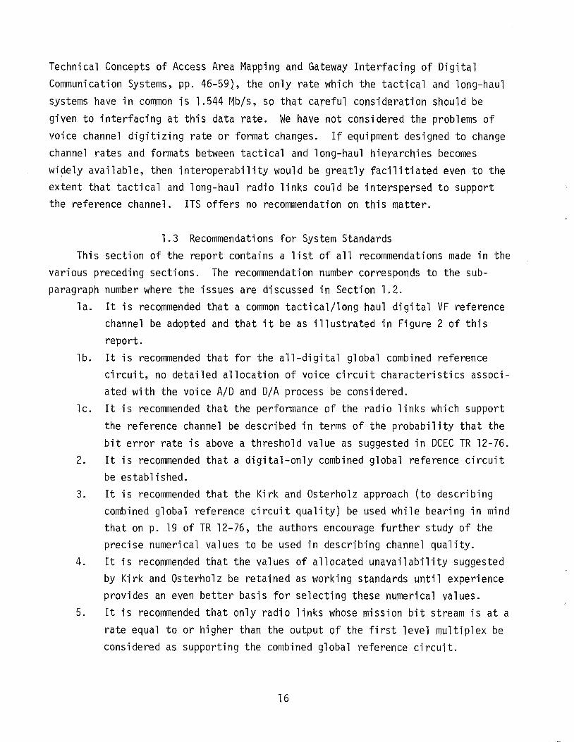
3.4 Improved Design ParametersThe major categories of design parameters in MIL-STD-188-322, with a number of
suggested additional categories are shown in Table 1. At the right of each parameter are columns which discuss the realism, cost performance tradeoff, evaluation,present value, and recommended value of the various parameters. A numerical valuehas been assigned to the cost and performance columns of the table to indicate therelative importance of the parameter and the relative cost of meeting the standard.The scale ranges from 1 to 10 with lower numbers indicating the more desirable ormore important condition. For instance, a performance weight of 10 would indicatethat the value of the particular parameter would have little influence on theperformance of the radio system. Similarly, a cost weight of 1 would indicate thatthe value required of the parameter could have a major cost impact on the radiosystem. A realism score of 1 indicates a realistic and realizable value and a scoreof 10 indicates that the parameter value is over-specified or should not bespecified.
The following paragraphs furthercolumn of some parameters in Table 1.order as they appear in the table.
30
Table 1. LOS Microwave Radio Equipment Parameter/Attribute Evaluation
How isParameter
Cost Performance Evaluated? Value Can ParameterIs Parameter Trade-off Calculated Provided in Recommended Be MeasuredRealistic Performance Cost Measured MIL-STO- Parameter with Link in
Parameters &Attributes Weight Weight Estimated 188-322 Value Service? Comments
MIl-STD-188-322 Parameters
Transmi tter
Output power 1 3 3 Meas. 1 & lOW Sallie No Standard should bepwr. meas. at ant.
Rf Interface Return loss 1 7 7 Meas. 26dB Sallie No Leave alone.Rf Trans. Line Ret. Loss 1 7 10 Meas. 14dB 20dB No Std. conmerc ia1
practice.Emission limitations 1 8 5 Meas. NTIA std. Same Yes Leave alone.Randomized Signal 6 10 Meas. Spec. compo Yes Requires further stu~
-30dBcw Clock Recovery from MilS 3 1 3 ObsV. para. 5.1 N/A No Leave alone.
Al ternative
Receiver
Noise figure 1 1 5 Meas. 10,14dB Same No Leave alone.Oynami c Range 1 2 9 Meas. 50dll Sallie No Reword standard.Adjacent Channel Interference
Sensitivity 3 4 5 Meas. *TIlO Study CCIR Report779.
Co-Channel InterferenceSensitivity 3 3 7 Meas. 20,25dll Same No Change design obj. to
std.; see CCIR Report779.
Carrier and Clock Recovery 10 1 3 Obsv. *TBO Not needed. Std. migltstifle initiative.
Return Loss In 1 7 7 Meas. 26dB 26dB No Std. Conmc l . Prac.Return Loss Out 1 7 10 Meas. 14dB 20dB No Std. Conine]. Prac.Reqenere t Ion 2 2 2 Meas. 10% ji tter Same No Leave alone.BER Threshold 1 1 3 Meas. TBO Modulation No Provide a minimum std.
dependent*T8D mee:, To Be Determined
Table 1. (cont.) LOS ~1icrowave Radio Equipment Parameter/Attribute Evaluation
How isParameter
Cost Performance Evaluated? Value Can ParameterIs Parameter Trade-off Calculated Provided in Recommended Be MeasuredRealistic Performance Cost Measured MIL-STD- Parameter with Link in
Parameters &Attributes Weight Weight Estimated 188-322 Val ue Service? Comments
Mi scellaneous
Transmitter &Receivel'Frequency Accuracy 1 4 6 Meas. 5 ppm Same No Exceeds NTIA std.
Transmitter &ReceiverFrequency Stability 1 4 6 Meas. 5 ppm Same Yes Should be specified
more completely.Da ta Samp1i ng in Receivel' 10 1 5 meas. On + to - of Not needed in std.
clock. + 25%w nom. dafa intvl.N Sensitivity to Timing Jitter 1 1 3 Meas. 12.5% abs. Same No May need slew rate
25% reI. standard.Modulation 10 5 9 Obsv• No Technique No recommend. -- Not needed in std.
requiredSystem Gain 10 2 9 Meas. 95dB No Not needed.Terminal Conf iqurati ons 2 2 7 Obsv. Move to Xmit Sec.Transmitter Redundancy
and Switching 2 2 2 Obsv. N/A N/A -- Leave alone.Transmitter Line Build-out 6 4 10 Obsv. 350 ns Same Yes Leave alone.Receiver Diversity Operation
and Swi tchi ng 1 2 7 Obsv. Move to Rc~r Sec.Receiver Line Build-out 2 4 10 Meas. 350 ns Same No Leave alone.Status Indicators and Alarms 3 2 4 Obsv. Para. 5.11. 1 Same -- Leave alone.Performance Monitors 2 2 5 Obsv . Para. 5.11.2 Same -- Leave alone.Input Power (Primary Power) 1 4 10 Obsv. Para. 5.13 Same -- Leave alone.
Table 1. (cont.) LOS Microwave Radio Equipment Parameter/Attribute Evaluation
How isParameter
Cost Performance Evaluated? Value Can ParameterIs Parameter Trade-off Calculated Provided in Recommended Be MeasuredRealistic Performance Cost Measured MIL-STD- Parameter with Link in
Parameter &Attributes Weight Weight Estimated 188-322 Value Service? Comments
Reliability
EMI --- 4 1 MIL STD 461462463
Human Engineering --- MIL STD 472Environmental Test Methods --- MIL STD 210Cl imatic Extremes --- 5 1 MIL STD 210Quantitative Reliability --- NIL STD 781
785Radio Reliability and
Definition of Failure 1 1 5 Calc. Para. Same -- Define radio set tow 5.12.5.2 incl. ant. &feeder.w Ma inta inabi l ity --- 2 1 MIL STD 470
471
Interface, Digital
Mission Bit Stream (2) 1 2 6 Meas. MIL STD Same No Need connector std.188-114 ref.
Service Channel Bit Stream 1 8 10 Meas. No value Same as MBS Yes Need performance std.provided Need connector std.
Clock In 1 3 2 Meas. MIL-STD- Same No Need connector std.188-114
Clock Out 1 2 6 Meas. MIL STD Same No Need connector std.188-114 ref.
I/O Signal Characteristics 1 2 5 --- --- --- No MIL STD 188 114Balanced to Unbalanced
Conversion 6 8 8 MIL-STD-188-114Da ta-Timi ng and Phasing 1 2 8 Meas. +10% Same Yes Leave alone.Da ta Ra tes 1 1 2 Obsv. Table III No recoumend • --- Requi res further stuc!lAlarm and Control Interfaces 3 2 9 Obsv. MIL STD Same No Need connector std.
188-114Service Channel 1 4 9 Meas. MIL-STD Same No Need connector std.
188-114
Table 1. (cont.) LOS Microwave Radio Equipment Parameter/Attribute Evaluation
Is ParameterRealistic
Parameter &Attributes
Additional Categories
Cost PerformanceTrade-off
Performance CostWeight Weight
How isParameterEvaluated?CalculatedMeasuredEstimated
ValueProvided inMIL-STD188-322
RecommendedParameterValue
Can ParameterBe Measuredwith Link inService? Conments
w.j::::,
Receiver BandwidthReceiver Spurious EmissionUse of Equalizer (Static or
Dynamic)Interface Mechanical StdAntenna System (Installation
and Protection)Transmission Line (Installation
and Protection)Loop-back and Fault Isolation
Test points -
45
62
2
88
49
9
Meas. NTIA STD NoMeas. Same No Need connector std.
To be det. -- Needs further studyObsv. Att. para.
Obsv . See att. para.
Obsv. See att. para.
Obsv • See att. para.
3.4.1 Output PowerThe levels of output power specified are consistent both with limits for
radiated power and with the capability of available equipment. The minimum power
specified is acceptable. The maximum power specified should be referred to theantenna port or expressed in terms of effective radiated power (NTIA, 1979, Section
5.10.4). This will allow transmitter powers higher than 10 watts to be used toovercome the effects of transmission l ine loss.
3.4.2 Randomized Transmitter Bit StreamThis characteristic of the radio transmitter requires further study. There are
two reasons to provide for increasing the randomness of a transmitted signal. One isto provide sufficient data transitions so that a clock signal can be recovered andthe other is to prevent the occurrence of high-level spectral components in theradiated microwave signal. It is anticipated that bulk encryption of the digitalbaseband would provide sufficient randomization for both purposes, but clear transmission might require further randomizing. The usual technique used is a selfsynchronizing scrambler at the transmitter and its complementary descrambler at thereceiver. The length of the shift registers used influences both the degree ofsuppression of spectral components and the extent of multiplication of bit errors inthe data stream. Balancing the desirability versus cost of these two randomizingresults should be used to guide the development of the standard. We offer norecommendation on this subject although CCIR Report 384-3 indicates a method forcalculating the intensity of spectral components.
3.4.3 Receiver Dynamic RangeThe value of dynamic range in the standard is reasonable, but it should be
described as the difference in dB between the receiver input signal level at thethreshold of minimum acceptable performance (a bit-error rate of 10-6 would agreewith DCAls TR-12-76) and the receiver input saturation level at which the bit-errorrate begins to increase again. We recommend this definition for receiver dynamicrange be adopted for standards purposes.
3.4.4 Adjacent Channel Interference SensitivityThe value of this parameter in the standard is lito be determined". We recom
mend that CeIR Report 779 (1978) be studied to arrive at a reasonable value of this
parameter.
35
3.4.5 Carrier and Clock Recovery
This characteristic of the radio receiver is lito be determined" in the currentstandard. Although the techniques for clock and carrier recovery are very importantin receiver operation, we recommend that this particular characteristic not bestandardized. To do so would stifle initiative and needlessly limit military radiosystem performance.
3.4.6 Bit-Error-Rate ThresholdThe bit-error-rate (BER) threshold of a microwave radio is a fundamental param
eter. The standard should define the BER threshold and should require, by means ofsome mathematical function which includes the data rate and the spectrum efficiency,a value of received signal level (RSL) at which the BER threshold is to occur. Anexample of such a function can be found in the DRAMA radio specification, CCC-74049USACEEIA (1976). We recommend that the BER threshold be defined as the steady RSLat which the BER is 10-6 to agree with Kirk and Osterholz (1976).
3.4.7 Transmitter and Receiver Frequency StabilityThe stability of the master oscillators which control the transmitter output
frequency and the local osci 11 ator frequency are currently requi red to be "betterthan 0.0005%". The standard should discuss short-term and long-term stabilityseparately since different effects tend to dominate different time frames. Forinstance, short-term instabilities are usually noise-like with zero average valuebut fairly wide rapid excursions while the long-term effect is a slow, steady driftor permanent change in frequency. We recommend that the standard be written toacknowledge both of these types of instability.
3.4.8 Data Sampling in ReceiverThe description of how the data stream is sampled in a microwave receiver and
the statement of the accuracy of the sampling are not needed in the standard. Toinclude this material may stifle initiative and needlessly restrict the performanceof military radios.
3.4.9 Modulation
The specification of a particular modulation scheme for digital radios isill advised. Further development of various modulation techniques could result inimproved performance. It would not seem necessary to deny the benefits of futuredevelopments to military system users.
36
3.4.10 System Gain
The value of system gain which is calculated for any particular radio is a
function of transmitter power and receiver BER threshold. Since transmitter poweris dictated by radio regulations and the receiver BER threshold can be determined bythe formula suggested under BER threshold, system gain is redundant. We recommendremoval of system gain from the standard.
3.4.11 Radio Reliability and Definition of FailureIn view of the importance of the antennas and transmission lines to the opera
tion of the radio link, it is suggested that any discussion of the radio set reliability include the antenna-feeder subsystem as an integral part of the radio setfor reliability discussion purposes. To do this will have two beneficial results.The first will be to emphasize to system designers the importance of the antenna andfeeder, and the second will be that an important contributor to radio link unavailability will be recognized so that a more realistic link availability value can beused. We recommend that the antenna and transmission line subsystem, includingtheir support systems, be considered part of the radio set for purposes of definingand calculating radio link reliability.
3.4.12 Data RatesThe data rates shown in Table III of MIL-STD-188-322 do not include a rate
equal to the output of the first level peM multiplex unit. It is not unlikely thatsome 24 voice channel links will be required within the Des. We suggest that furtherstudy be done on this issue.
3.4.13 Use of Static or Dynamic EqualizerThe suggestion that this subject be included in the standard is made with the
expectation that such a device will not be required on every radio purchased. Theuse of an equalizer is justified only where very high data rates (over 50 Mb/s) areused or on links which are subject to especially severe multipath effects. Theinclusion of this topic in the standard is intended to facilitate the purchase ofsuch a unit if one is needed. We recommend that consideration be given to developing a standard for an rf equalizer.
37
3.4.14 Interface Mechanical StandardsThe problem of interconnection among various equipments produced by various
manufacturers and installed in many different configurations could be significantlyeased if a small number of mechanical connector standards could be developed. Sucha standard should specify:
a. One waveguide flange for each frequency band.b. A coaxial rf transmission line fitting.c. A coaxial rf and IF fitting for use inside the radio set.d. An unbalanced data and clock fitting type for input, output,
and internal interconnection.e. A balanced data and clock fitting type for input, output, and
internal interconnection.f. A standard multi pin connector for control input and for alarm,
status, and monitor outputs with designated functions for all pins.
It is anticipated that these fittings could be selected from current JAN types whichwould make further detailed connector design and specification unnecessary. Anexample of a waveguide mechanical interface table is given in the DRAMA specification, eee 74049, paragraph 3.5.4.1. We recommend that such a set of mechanicalstandards be adopted. These standards will tend to stifle innovation somewhat butat an acceptable price.
3.4.15 Antenna and Transmission Line Installation and ProtectionAs has been stated elsewhere in this report, the problems with transmission
line and antenna installation which the authors have observed demand resolution. Wehave been unable to determine whether the observed problems arise because of inadequate standards or because the standards of installation are not met. If inadequatestandards are the problem, we recommend development of standards and their inclusionin the microwave radio standard. If adequate standards exist, we recommend thatthey become part of the microwave radio standard.
3.4.16 Loop-Back and Fault Isolation Test PointsThe operation of a radio system and the prompt restoral of service after a
failure require that fault isolation be accomplished very rapidly (Kirk and Osterholz, 1976, pp. 25-6) so that repairs can be carried out. Many problems with modernsystems are so complex that merely isolating the station which has a problem is
38
difficult. If all of the equipment at a station could be looped back in-house, muchmore rapid fault isolation would be possible. We recommend that the standardrequire that radios be equipped with rf, IF (if possible) and mission bit stream
loop-back and fault isolation test ports which can be rapidly accessed withoutremoving the radio from an operational configuration (without opening the waveguide,for instance).
3.5 Field Modification UpgradesConsiderable thought has been given to this subject and a number of suggestions
are offered. The possible improvements range from simple additions to equipment,through major changes in radio site organization, and into the organization ofsupport functions. In all cases, the suggestions reflect either common practice inother areas of communication technology or improvements suggested by competentauthorities.
3.5.1 Move RF Head Closer to AntennaThis suggestion would involve locating an optional low-noise amplifier, local
oscillator multiplier chain (or parts of it), the mixer and an IF amplifier remotefrom the remainder of the radio and placing them directly at the antenna. Thistechnique is commonly used in satellite earth stations where the rf system islocated immediately behind a Cassagranian-fed parabolic reflector. The advantagesof such an arrangement are that the receiver line loss is eliminated as are theeffects of rf reflections due to poorly matched terminations. The advantage increases markedly as carrier frequency increases. A number of manufacturers producesealed radio units for outdoor mounting so the technology for such a technique isavailable. Of course, consideration must be given to providing adequate access tothe rf head in case of failure.
3.5.2 Move All Radio Equipment Closer to AntennaThe second suggestion is similar to the first one, but its realization would
only be practical on sites where a steel tower is being replaced by a concrete one.It is suggested that, in the future, all such concrete towers be designed to accommodate the radio sets and at least the highest level multiplex inside the towermidway between the vertically spaced diversity antennas. Such an arrangement wouldeliminate almost all line loss and rf reflection problems and would allow reducedtransmitter power to be used in many cases. This arrangement is commonly used by
39
the European tele.phone administrations and by television broadcast organizations.The savings from doing this would include the cost of purchasing ~nd installing
long, expensive waveguide runs. Such a tower would provide better access to andprotection for the antennas.
3.5.3 Transmit from Either Diversity Antenna
Another suggestion which would complement the previous two is to transmit fromeither di versity antenna (only one transmitter woul d be operating at anyone time).The advantage of doing this would be to provide redundancy in the only part of therf system which is not protected .now. This could be done on new installations atvery low cost and could be retrofitted at moderate cost since only the transmitterwaveguide or coaxial plumbing would need to be changed.
3.5.4 Improve Antenna and Feeder InstallationAs has been stated previously, the antenna and transmission line installations
on many parts of the DeS have suffered numerous failures from faulty engineering,improper installation, and shoddy materials, as discussed in Section 3.3 of thisreport. As transmission line systems age, the initial problems whose effects may beonly minor can and usually do cause more and more system degradation. A carefulreview of system test data and performance records would show which links would bemost likely to benefit from an upgraded antenna system. The most obvious symptom ofantenna system problems would be reduced median received signal level (RSL). Unusual
variations in RSL could also be indicative of the same type of problem.
3.5.5 Install Equalizers on Bad PathsDigital radio links which perform below expected levels of either quality or
availability might benefit from the installation of equalizers in the receivers.Before this technique is attempted however, all other possible causes of poor performance such as antenna alignment, transmission line quality, and electronic equipmentalignment, should be eliminated by very careful testing. The technique should notbe used for mission bit streams less than 12 Mb/s. furthermore, only radio linkswhich are subject to serious and continuous multipath effects are candidates forthis treatment.
40
3.5.6 Install Transmit and Receiver Test PortsThe preceding discussions have emphasized the necessity of collecting accurate
data on various parameters of link operation. To assist in this data collection,transmitter and receiver test ports should be required on new equipment and shouldbe installed on old equipment which lacks them. These installations need not be
costly and would permit much more thorough testing than is possible without them.The test ports would allow a milliwatt-level sample of the transmitter signal to be
extracted and would allow the injection of a calibrated level into the receiver.This would make it possible to analyze the transmitted signal, to inject a calibrating signal into the receiver, or, using suitable attenuators and translation
oscillators, to connect the radio set back-to-back at the rf level for troubleshooting or testing.
3.6 Specific Questions From Statement of WorkThe following sections answer the specific questions contained in the statement
of work.5a. Are interfaces specified and described so as to minimize problems when the
equipment is used with other equipment?
No. The lack of a complete connector mechanical standard for each of thevarious interfaces is a serious omission, as has been noted earlier in
this report.
5b. Do any parts of the standard discourage innovation?
Yes. However, a standard must freeze technology at some point, particularly inregard to such things as interface connector standards. Some of thestandards tend to become too involved with details of function such asthose which discuss the orderwire and maintenance coordination circuitvoice-channel digitization technique and the specification of details ofthe receiver data-sampling process. These specifications of what processis to be used to arrive at a result do not belong in a technical standard.Table 3.1 notes in the Comments column which parameters or characteristicsshould not be standardized.
41
5c. Are values specified in the standard directly measurable?
Yes. Two different areas of the standard will prove difficult and time-consum
ing to establish compliance with. One is the radio frequency stability
criterion required for the transmitter and receiver and the other is the
bit-error rates required. In previous sections of this standard, we have
suggested rewriting the frequency stability section and changing the bit
error rate at threshold.
5d. Are design objectives provided and stated as such?
Yes.
5e. Can design objective performance be improved?
No. Most areas where design objectives are stated are either within the state
of the art or are construction features which should remain design objec
tives. See 5g.
5f. Should additional design objectives be added?
No. There are no areas of the standard where the state of the art is changing
rapidly enough to require further design objectives to be added.
5g. Is there a good probability that the design objectives could become stan
dards in the next 5 years?
Yes. All design objectives except those involving construction features can bechanged to standards at present.
3.7 Conclusions and Recommendations for Equipment Standards
The November 1, 1976 issue of MIL-STD-188-322 was an excellent guide to the
specification of radios during its early years, but technology has now made certain
changes necessary.
Our primary recommendation under task 2 is that the organization be made more
logical and so we have included a suggested outline for the standard as an appendix.
42
A number of recommendations resulted from our studies made under subtask 3.These recommendations are listed in Section 3 of the report.
Our efforts on task 4 involved determining what techniques could be part of thestandard and also be used to upgrade DCS equipment operation by field modifications.These recommendations are covered in detail in Section 3.5.
Task 5 requested the answers to specific questions and Section 3.6 containsthese answers and supporting rationale.
4. CONCLUSIONS
The particular conclusions and recommendations dealing with each section of thereport are presented at the end of each section and will not be repeated here.Three major conclusions can be stated which apply to the entire subject of thecommon long-haul/tactical standards.
1. There is a serious need to develop a common long-haul/tactical digitalreference circuit which can be described in the terms used in the DCEC TR12-76 report.*
2. Any new digital standard should exclude consideration of FDM/FM transmission links as part of the common long-haul/tactical global referencecircuit and the composition of the standards should reflect this policy.
3. The common long-haul/tactical digital transmission subsystem and equipmentstandards should be revised and augmented as described in Sections 2 and 3of thi s report.
*Note: The requirements stated in this document are based on engineering judgmentswhich are intended to assure a specified circuit time availability and circuitquality. DCEC TR-12-76, page 19, indicates a need for user subjective evaluationand changes in the requirements. A possible approach to formulating quantitativeuser criteria is the application of Interim Federal Standard 1033. However, untilsuch criteria are available, the DCEC TR-12-76 report should be used as the basisfor the development of the global reference circuit and the long-haul/tacticalstandards.
43
5. REFERENCES
Anderson, C., S. Barber, and R. Patel (1977), Propagation experiments toshow path to success, Telesis, December.
CCIR (1978), Recommendations and Reports of the CCIR, Volume IV: FixedService Using Communication Satellites, Recommendation 446-2: CarrierEnergy Dispersal for Systems Employing Angle Modulation by AnalogueSignals or Digital Modulation in the Fixed Satellite Service (ITU,Geneva, Switzerland).
CCIR (1978), Recommendations and Reports of the CCIR, Volume IV, FixedService Using Communication Satellites, Recommendation 522: AllowableBit Error Rates at the Output of the Hypothetical Reference Circuit forSystems in the Fixed Satellite Service Using Pulse-Code Modulation forTelephony (ITU, Geneva, Switzerland).
CCIR (1978), Recommendations and Reports of the CCIR, Volume V: Propagationin Non-ionized Media, Report 338-3: Propagation Data Required forLine-of-Sight Radio Relay Systems (ITU, Geneva, SWitzerland).
CCIR (1978), Recommendations and Reports of the CCIR, Volume V: Propagationin Non-Ionized Media, Report 238-3: Propagation Data Required for TransHorizon Radio-Relay Systems (ITU, Geneva, Switzerland).
CCIR (1978), Recommendations and Reports of the CCIR, Volume IX: FixedService Using Radio-Relay Systems, Frequency Sharing and CoordinationBetween Systems in the Fixed Satellite Service and Radio-Relay Systems,Report 445-2: Availability and Reliability of Radio-Relay Systems(ITU, Geneva, Switzerland).
CCIR (1978), Recommendations and Reports of the CCIR, Volume IX: FixedService Using Radio-Relay Systems, Frequency Sharing and Coordination BetweenSystems in the Fixed Satellite Service and Radio-Relay Systems, Recommendation 556: Hypothetical Reference Digital Path for Radio-Relay Systems forTelephony; Systems with a Capacity above the Second Hierarchical Level(ITU, Geneva, Switzerland).
CCIR (1978), Recommendations and Reports of the CCIR, Volume IX: FixedService Using Radio-Relay Systems, Frequency Sharing and Coordination BetweenSystems in the Fixed Satellite Service and Radio-Relay Systems, Report378-3: Characteristics and Performance Objectives for Digital Radio-Relay Systems (ITU, Geneva, Switzerland).
CCIR (1978), Recommendations and Reports of the CCIR, Volume IX: FixedService Using Radio-Relay Systems, Frequency Sharing and CoordinationBetween Systems in the Fixed Satellite Service and Radio-Relay Systems,Report 779: Interference in Digital Radio-Relay Systems with CoherentPSK Modulation (ITU, Geneva, Switzerland).
Hause, L. G., and D. R. Wortendyke (1979), Automated Digital System EngineeringModel, NTIA Report 79-18. (NTIA-ITS, 325 Broadway, Boulder, CO 80302.)
44
Kirk, K. W., and J. L. Osterholz (1976), DCS Digital Transmission System Performance, TR 12-76 (Defense Communications and Electronics Center,Reston, Virginia).
Lotz, W. E., Jr., and P. R. Klocko, Memorandum of Understanding (DefenseCommunications Agency, Washington, DC 20305).
MIL STD 188-188 (1972), Military Standard: Common Long Haul and TacticalCommunication System Technical Standards (Naval Publications and FormsCenter, 5801 Tabor Ave., Philadelphia, Pennsylvania).
MIL STD 188-144 (1978), Military Standard (Draft): Subsystems Design andEngineering Standards for Common Long Haul and Tactical TroposphericScatter Transmission (U.S. Naval Publications and Forms Center, 5801Tabor Ave., Philadelphia, Pennsylvania).
MIL STD 188-145 (1977), Military Standard (Draft): Subsystem Design/Engineering and Design Technical Standards for Common Long Haul andTactical Line of Sight (LOS) MIcrowave RAdio Transmission (Naval Publications and Forms Center, 5801 Tabor Ave., Philadelphia, Pennyslvania).
MIL STD 188-200 (1978), Military Standard (Second Draft): System Design andEngineering Standards for Tactical Communications (Naval Publicationsand Forms Center, 5801 Tabor Ave., Philadelphia, Pennsylvania).
MIL STD 188-322 (1976), Military Standard: Subsystem Design/Engineering andEquipment Technical Design Standards for Long Haul Line of Sight (LOS)Digital Microwave Radio Transmission (Naval Publications and FormsCenter, 5801 Tabor Ave., Philadelphia, Pennsylvania).
NTIA (1979), Manual of Regulations and Procedures for Federal RadioFrequency Management, Chapter 5: Technical Standards Requirementsand Objectives (NTIA, 1800 G St., N.W., Washington, DC 20504).
U.S. Army CEEIA (1976), Specification for Radio Set, AN/FRC-163( ), CCC-74049(Headquarters, U.S. Army Communications-Electronics EngineeringInstallation Agency, Fort Huachuca, AZ 85613).
U.S. Department of Commerce (1979), Department Administrative Order 20-21:Conversion to Metric Usage (U.S. Department of Commerce, Office ofthe Secretary, Main Commerce Building, Washington, D.C.)
This appendix consists of an outline for a combined tactical/long-haul standardfor microwave radio sets. This outline is our attempt to organize MIL~STD-188-322
in a logical manner. We do not purport to have discovered the only possible organization for the standard but merely suggest it as more logical than the existing
format. The outline is shallow, being only four categories deep, but we feel thatit would be fairly easy to expand to include all of the material in the currentissue of MIL-STD-188-322 and all of the suggested changes mentioned in this report.
Proposed Outline for MIL-STD-188-322
1. Scope2. Referenced Documents3. Terms and Definitions4. General Requirements
NTIA Report 81-744. TITLE AND SUBTITLE 5. Publication Date
RECOMMENDATIONS FOR DIGITAL RADIO COMMON May 1981TACTICAL/LONG-HAUL STANDARDS 6. Performing Organization Code
7. AUTHOR(S) 9. Project/Task/Work Unit No.
J. E. Farrow and L.G. Hause 91044358. PERFORMING ORGANIZATION NAME AND ADDRESS
Institute for Telecommunication SciencesNational Telecommunications and Informati on 10. Contract/Grant No.
AdministrationU.S. Department of Commerce, Boulder, CO 80303 La. 79-2
11. Sponsoring Organization Name and Address 12. Type of Report and Period Covered
Defense Communication Agency Technical ReportDefense Communications Engineering Center 04/01/80-09/30/801860 Wiehle Avenue 13.
Reston, VA 2209014. SUPPLEMENTARY NOTES
15. ABSTRACT (A 200-word or less factual summary of most significant information. If document includes a significant bibliography or literaturesurvey, mention it here.)
This report is the sum of a three-part effort by the Institutefor Telecommunication Sciences (ITS) to provide technical recom-mendations for the DCS Long-Haul Tactical Common system, subsystem,and equipment technical standards for digital radio. The work wassponsored by the Defense Communications Engineering Center,Reston, VA.
Primary recommendations for the system standards include sug-gested reference circuit and channel distances within a common over-seas DCS terrestrial segment; the suggestion that only digitalsubsystems be included -in the global reference circuit; and thestatement that only parameters directly measurable in digita1 systems
(CONTINUED)16. Key Words (Alphabetical order, separated by semicolons)
digital microwave; equipment standard; radio system standard;subsystem standards; tactical communication
17. AVAILABILITY STATEMENT 18. Security Class. (This report) 20. Number of pages
n UNLIMITED. Unclassified 6019. Security Class. (This page) 21. Price:
D FOR OFFICIAL DISTRIBUTION. Unclassified
15. ABSTRACT (Cont.)
(such as bit-error-rate) be used in defining performance. Themain recommendations for subsystems standards include a recommendedscope for subsystem standards; suggestions for specific content inwhich appropriate standards and subsystem parameters are identified;and exclusion of all reference to FDM/FM parameters from new drafts.Some important guidelines for the equipment standards include anoutline for the equipment standards; recommendations on the realismand practicality of design parameters; and recommendations onpossible techniques to be included in the standard for upgradingexisting facilities.
* u.s. GOVERNMENT PRINTING OFFICE: 1981 - 780-094/356 Region No.8