12
Technical Note Recommendations for Electrofusion Welding Specifications ISSUE 1.0 Ref: TN017 Committee Document

Technical Note
Recommendations for Electrofusion
Welding Specifications
ISSUE 1.0
Ref: TN017
Committee Document
TN017 ISSUE 1.0 Page 1
Disclaimer
In formulating this guideline PIPA has relied upon the advice of its members and,
where appropriate, independent testing.
Notwithstanding, users of the guidelines are advised to seek their own independent
advice and, where appropriate, to conduct their own testing and assessment of
matters contained in the guidelines, and to not rely solely on the guidelines in
relation to any matter that may risk loss or damage.
PIPA gives no warranty concerning the correctness of accuracy of the information,
opinions and recommendations contained in the guidelines. Users of the guidelines
are advised that their reliance on any matter contained in the guidelines is at their
own risk.

TN017 ISSUE 1.0 Page 2
Recommendations for Electrofusion Welding Specifications
It is intended that this document is read in conjunction with the Plastic Industry Pipe
Association Technical Guideline POP001 Electrofusion Jointing of PE Pipes and
Fittings for Pressure Applications.
The purpose of this document is to provide commentary and information in addition
to that contained in POP001 to assist in the preparation of specifications involving
Electrofusion welding of polyethylene pipelines.
The document includes recommendations for:
Required training/certification levels for installers and demonstrated
experience
Minimum requirements for installation tooling, measuring and welding
equipment
Managing environmental factors on the work site
Record keeping and joint identification information
Quality control measures for monitoring and assessing installation quality
It is intended that this document assist asset owners in correctly specifying
the installation requirements for the construction of electrofusion joints in PE
pipelines.
1 TRAINING AND INSTALLER EXPERIENCE
Operator-trained, experienced and qualified to PMBWELD302B — Electrofusion
weld Polyethylene Pipelines with a current statement of attainment. Trained
welders also need to demonstrate relevant ongoing experience and attendance at
refresher courses. Typically the period between refresher training is of the order of 2
years. The timing of refresher training is set by the Registered Training Organisation
(RTO) or training body. Attendance at refresher training is often a requirement of the
client – for example the Australian water industry and the coal seam gas industry
have required this for several years. Plastics Industry Pipe Association supports the
need for refresher training to ensure:
Key skills are reinforced and well understood
Operators are aware of developments in surface preparation techniques
Operators are aware of developments in electrofusion fittings and associated
equipment
All operators planning to conduct electrofusion procedures on a project should have
an up to date training statement from an accredited RTO. Industry experience has
shown that projects utilising untrained operators working under the part time

TN017 ISSUE 1.0 Page 3
supervision of trained personnel have a significantly higher risk of welding problems
compared to those projects where all operators and supervisors have been formally
trained.
Operators should have demonstrated competency and experience with the sizes and
types of fittings being installed on the project. Demonstrated competence could
include:
Documented experience, constructing PE joints of the same fitting type and
diameter e.g. weld records and or joint information records from a previous
project which show that the welders proposed for the project have
successfully completed work in the diameters specified,
Records of successful pre-qualification weld evaluation testing on fitting types
to be used on the project, e.g. third party destructive test results to
ISO 13954, ISO 13955, ISO 13956 or ISO 21751 as appropriate showing
pass results,
References from other clients.
1.1 Suggested Minimum Installation Tools and Measuring Equipment
It is important that installers are equipped with the correct tools and measuring
equipment to ensure all joints are prepared in accordance with both the
manufacturer’s and industry guidelines, using polyethylene pipe that complies with
Australian Standard AS/NZS 4130. This is to ensure factors including surface
preparation, cleaning, permissible joint geometry, control of welding environment and
welding parameters are correctly managed. To achieve this, the installers will need
to have access to a range of tools, environmental controls and measuring devices for
each type of fitting being used at the job site. If the installer plans to use multiple
installation crews, then it is important that each crew has all the equipment required
for successful welding.
The installer should be able to demonstrate that welding will be conducted in
accordance with POP001. POP001 provides a full listing of suggested measuring
and installation aids in Section 1.3 Required Equipment. It is important that all items
listed in POP001 are available to each installation crew. The following table explains
the importance and reason for each item listed.
Table 1
Category Items Importance
Measuring Equipment
Steel rule
Calliper Pi tape
The recommendations in POP001 for assembled joint geometry require that the operator has the equipment and skill level necessary to measure the average diameter and ovality of the pipe, both before and after preparation to ensure it complies with the dimensional tolerances listed in PIPA POP001 Table 3 and Sections 2.1.6.1 “Pipe end
TN017 ISSUE 1.0 Page 4
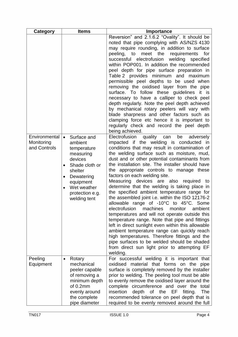
Category Items Importance
Reversion” and 2.1.6.2 “Ovality”. It should be noted that pipe complying with AS/NZS 4130 may require rounding, in addition to surface peeling, to meet the requirements for successful electrofusion welding specified within POP001. In addition the recommended peel depth for pipe surface preparation in Table 2 provides minimum and maximum permissible peel depths to be used when removing the oxidised layer from the pipe surface. To follow these guidelines it is necessary to have a calliper to check peel depth regularly. Note the peel depth achieved by mechanical rotary peelers will vary with blade sharpness and other factors such as clamping force etc hence it is important to regularly check and record the peel depth being achieved.
Environmental Monitoring and Controls
Surface and ambient temperature measuring devices
Shade cloth or shelter
Dewatering equipment
Wet weather protection e.g. welding tent
Electrofusion quality can be adversely impacted if the welding is conducted in conditions that may result in contamination of the welding surface such as moisture, mud, dust and or other potential contaminants from the installation site. The installer should have the appropriate controls to manage these factors on each welding site. Measuring devices are also required to determine that the welding is taking place in the specified ambient temperature range for the assembled joint i.e. within the ISO 12176-2 allowable range of -10°C to 45°C. Some electrofusion machines monitor ambient temperatures and will not operate outside this temperature range. Note that pipe and fittings left in direct sunlight even within this allowable ambient temperature range can quickly reach high temperatures. Therefore fittings and the pipe surfaces to be welded should be shaded from direct sun light prior to attempting EF welding.
Peeling Equipment
Rotary mechanical peeler capable of removing a minimum depth of 0.2mm evenly around the complete pipe diameter
For successful welding it is important that oxidised material that forms on the pipe surface is completely removed by the installer prior to welding. The peeling tool must be able to evenly remove the oxidised layer around the complete circumference and over the total insertion depth of the EF fitting. The recommended tolerance on peel depth that is required to be evenly removed around the full
TN017 ISSUE 1.0 Page 5
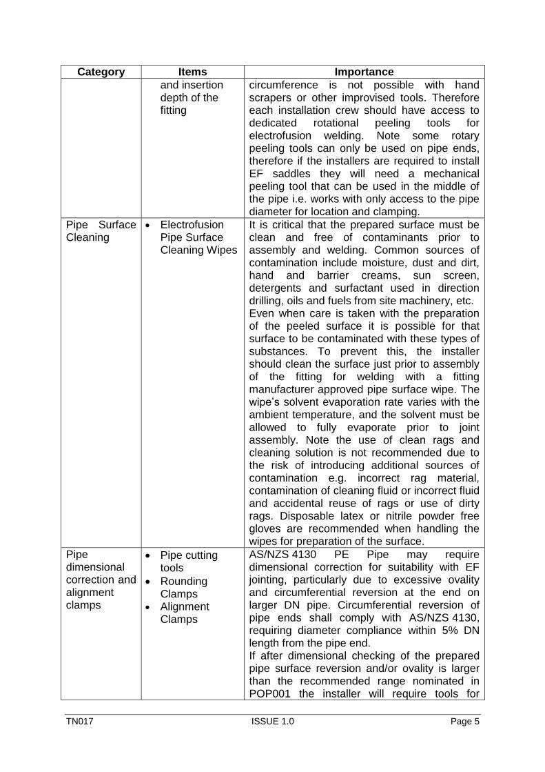
Category Items Importance
and insertion depth of the fitting
circumference is not possible with hand scrapers or other improvised tools. Therefore each installation crew should have access to dedicated rotational peeling tools for electrofusion welding. Note some rotary peeling tools can only be used on pipe ends, therefore if the installers are required to install EF saddles they will need a mechanical peeling tool that can be used in the middle of the pipe i.e. works with only access to the pipe diameter for location and clamping.
Pipe Surface Cleaning
Electrofusion Pipe Surface Cleaning Wipes
It is critical that the prepared surface must be clean and free of contaminants prior to assembly and welding. Common sources of contamination include moisture, dust and dirt, hand and barrier creams, sun screen, detergents and surfactant used in direction drilling, oils and fuels from site machinery, etc. Even when care is taken with the preparation of the peeled surface it is possible for that surface to be contaminated with these types of substances. To prevent this, the installer should clean the surface just prior to assembly of the fitting for welding with a fitting manufacturer approved pipe surface wipe. The wipe’s solvent evaporation rate varies with the ambient temperature, and the solvent must be allowed to fully evaporate prior to joint assembly. Note the use of clean rags and cleaning solution is not recommended due to the risk of introducing additional sources of contamination e.g. incorrect rag material, contamination of cleaning fluid or incorrect fluid and accidental reuse of rags or use of dirty rags. Disposable latex or nitrile powder free gloves are recommended when handling the wipes for preparation of the surface.
Pipe dimensional correction and alignment clamps
Pipe cutting tools
Rounding Clamps
Alignment Clamps
AS/NZS 4130 PE Pipe may require dimensional correction for suitability with EF jointing, particularly due to excessive ovality and circumferential reversion at the end on larger DN pipe. Circumferential reversion of pipe ends shall comply with AS/NZS 4130, requiring diameter compliance within 5% DN length from the pipe end. If after dimensional checking of the prepared pipe surface reversion and/or ovality is larger than the recommended range nominated in POP001 the installer will require tools for
TN017 ISSUE 1.0 Page 6
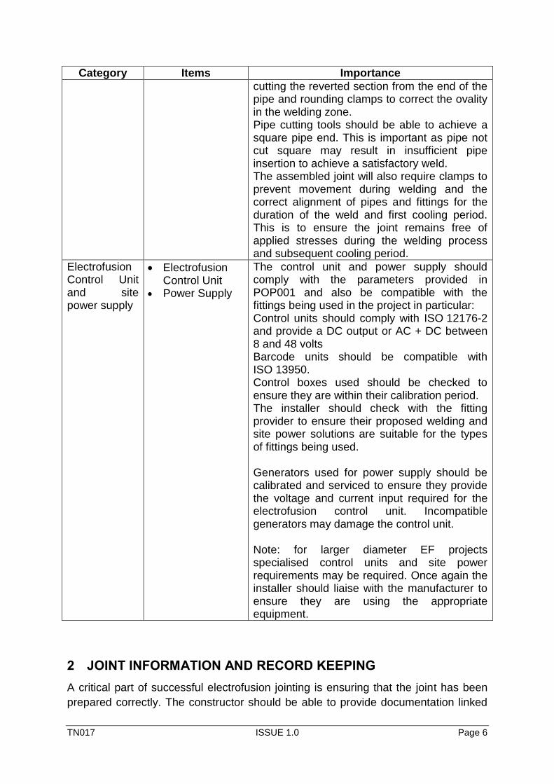
Category Items Importance
cutting the reverted section from the end of the pipe and rounding clamps to correct the ovality in the welding zone. Pipe cutting tools should be able to achieve a square pipe end. This is important as pipe not cut square may result in insufficient pipe insertion to achieve a satisfactory weld. The assembled joint will also require clamps to prevent movement during welding and the correct alignment of pipes and fittings for the duration of the weld and first cooling period. This is to ensure the joint remains free of applied stresses during the welding process and subsequent cooling period.
Electrofusion Control Unit and site power supply
Electrofusion Control Unit
Power Supply
The control unit and power supply should comply with the parameters provided in POP001 and also be compatible with the fittings being used in the project in particular: Control units should comply with ISO 12176-2 and provide a DC output or AC + DC between 8 and 48 volts Barcode units should be compatible with ISO 13950. Control boxes used should be checked to ensure they are within their calibration period. The installer should check with the fitting provider to ensure their proposed welding and site power solutions are suitable for the types of fittings being used. Generators used for power supply should be calibrated and serviced to ensure they provide the voltage and current input required for the electrofusion control unit. Incompatible generators may damage the control unit. Note: for larger diameter EF projects specialised control units and site power requirements may be required. Once again the installer should liaise with the manufacturer to ensure they are using the appropriate equipment.
2 JOINT INFORMATION AND RECORD KEEPING
A critical part of successful electrofusion jointing is ensuring that the joint has been
prepared correctly. The constructor should be able to provide documentation linked
TN017 ISSUE 1.0 Page 7
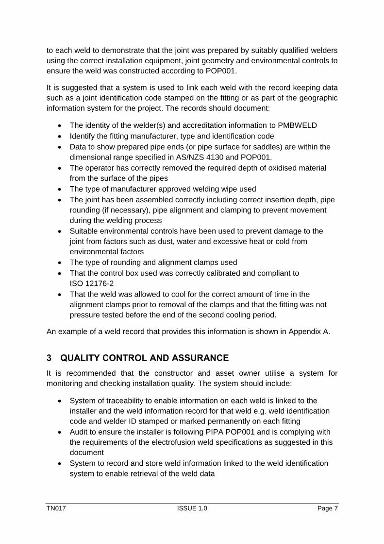
to each weld to demonstrate that the joint was prepared by suitably qualified welders
using the correct installation equipment, joint geometry and environmental controls to
ensure the weld was constructed according to POP001.
It is suggested that a system is used to link each weld with the record keeping data
such as a joint identification code stamped on the fitting or as part of the geographic
information system for the project. The records should document:
The identity of the welder(s) and accreditation information to PMBWELD
Identify the fitting manufacturer, type and identification code
Data to show prepared pipe ends (or pipe surface for saddles) are within the
dimensional range specified in AS/NZS 4130 and POP001.
The operator has correctly removed the required depth of oxidised material
from the surface of the pipes
The type of manufacturer approved welding wipe used
The joint has been assembled correctly including correct insertion depth, pipe
rounding (if necessary), pipe alignment and clamping to prevent movement
during the welding process
Suitable environmental controls have been used to prevent damage to the
joint from factors such as dust, water and excessive heat or cold from
environmental factors
The type of rounding and alignment clamps used
That the control box used was correctly calibrated and compliant to
ISO 12176-2
That the weld was allowed to cool for the correct amount of time in the
alignment clamps prior to removal of the clamps and that the fitting was not
pressure tested before the end of the second cooling period.
An example of a weld record that provides this information is shown in Appendix A.
3 QUALITY CONTROL AND ASSURANCE
It is recommended that the constructor and asset owner utilise a system for
monitoring and checking installation quality. The system should include:
System of traceability to enable information on each weld is linked to the
installer and the weld information record for that weld e.g. weld identification
code and welder ID stamped or marked permanently on each fitting
Audit to ensure the installer is following PIPA POP001 and is complying with
the requirements of the electrofusion weld specifications as suggested in this
document
System to record and store weld information linked to the weld identification
system to enable retrieval of the weld data
TN017 ISSUE 1.0 Page 8
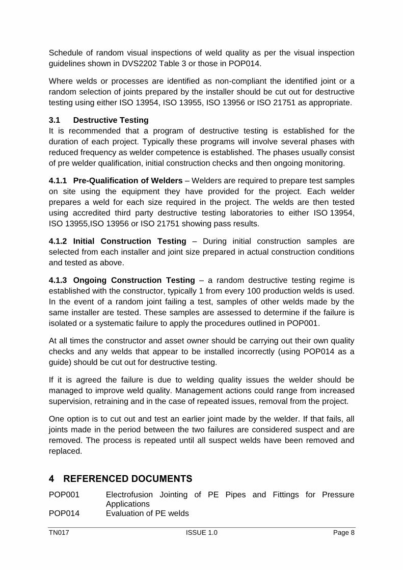
Schedule of random visual inspections of weld quality as per the visual inspection
guidelines shown in DVS2202 Table 3 or those in POP014.
Where welds or processes are identified as non-compliant the identified joint or a
random selection of joints prepared by the installer should be cut out for destructive
testing using either ISO 13954, ISO 13955, ISO 13956 or ISO 21751 as appropriate.
3.1 Destructive Testing
It is recommended that a program of destructive testing is established for the
duration of each project. Typically these programs will involve several phases with
reduced frequency as welder competence is established. The phases usually consist
of pre welder qualification, initial construction checks and then ongoing monitoring.
4.1.1 Pre-Qualification of Welders – Welders are required to prepare test samples
on site using the equipment they have provided for the project. Each welder
prepares a weld for each size required in the project. The welds are then tested
using accredited third party destructive testing laboratories to either ISO 13954,
ISO 13955,ISO 13956 or ISO 21751 showing pass results.
4.1.2 Initial Construction Testing – During initial construction samples are
selected from each installer and joint size prepared in actual construction conditions
and tested as above.
4.1.3 Ongoing Construction Testing – a random destructive testing regime is
established with the constructor, typically 1 from every 100 production welds is used.
In the event of a random joint failing a test, samples of other welds made by the
same installer are tested. These samples are assessed to determine if the failure is
isolated or a systematic failure to apply the procedures outlined in POP001.
At all times the constructor and asset owner should be carrying out their own quality
checks and any welds that appear to be installed incorrectly (using POP014 as a
guide) should be cut out for destructive testing.
If it is agreed the failure is due to welding quality issues the welder should be
managed to improve weld quality. Management actions could range from increased
supervision, retraining and in the case of repeated issues, removal from the project.
One option is to cut out and test an earlier joint made by the welder. If that fails, all
joints made in the period between the two failures are considered suspect and are
removed. The process is repeated until all suspect welds have been removed and
replaced.
4 REFERENCED DOCUMENTS
POP001 Electrofusion Jointing of PE Pipes and Fittings for Pressure Applications
POP014 Evaluation of PE welds
TN017 ISSUE 1.0 Page 9
DVS Technical Codes on Plastics Joining Technologies English Edition Volume 3
DVS 2202-1(2006-07) Imperfection in Thermoplastic Welded Joints, Features, description and evaluation
AS/NZS 4129 Fittings for polyethylene (PE) pipes for pressure applications AS/NZS 4130 Polyethylene (PE) pipes for pressure applications AS/NZS 2033 Installation of Polyethylene Pipe Systems ISO 13954 Plastics pipes and fittings — Peel decohesion test for polyethylene
(PE) electrofusion assemblies of nominal outside diameter greater than or equal to 90 mm
ISO 13955 Plastics pipes and fittings — Crushing decohesion test for polyethylene (PE) electrofusion assemblies
ISO 13956 Plastics pipes and fittings — Decohesion test of polyethylene (PE) saddle fusion joints -- Evaluation of ductility of fusion joint interface by tear test
ISO 21751 Plastics pipes and fittings — Decohesion test of electrofusion assemblies -- Strip-bend test
ISO 12176-2 Plastics pipes and fittings — Equipment for fusion jointing polyethylene systems — Part 2: Electrofusion
TN017 ISSUE 1.0 Page 10
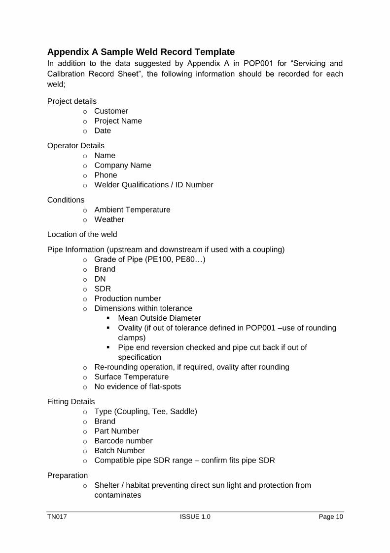
Appendix A Sample Weld Record Template
In addition to the data suggested by Appendix A in POP001 for “Servicing and
Calibration Record Sheet”, the following information should be recorded for each
weld;
Project details
o Customer
o Project Name
o Date
Operator Details
o Name
o Company Name
o Phone
o Welder Qualifications / ID Number
Conditions
o Ambient Temperature
o Weather
Location of the weld
Pipe Information (upstream and downstream if used with a coupling)
o Grade of Pipe (PE100, PE80…)
o Brand
o DN
o SDR
o Production number
o Dimensions within tolerance
Mean Outside Diameter
Ovality (if out of tolerance defined in POP001 –use of rounding
clamps)
Pipe end reversion checked and pipe cut back if out of
specification
o Re-rounding operation, if required, ovality after rounding
o Surface Temperature
o No evidence of flat-spots
Fitting Details
o Type (Coupling, Tee, Saddle)
o Brand
o Part Number
o Barcode number
o Batch Number
o Compatible pipe SDR range – confirm fits pipe SDR
Preparation
o Shelter / habitat preventing direct sun light and protection from
contaminates
TN017 ISSUE 1.0 Page 11
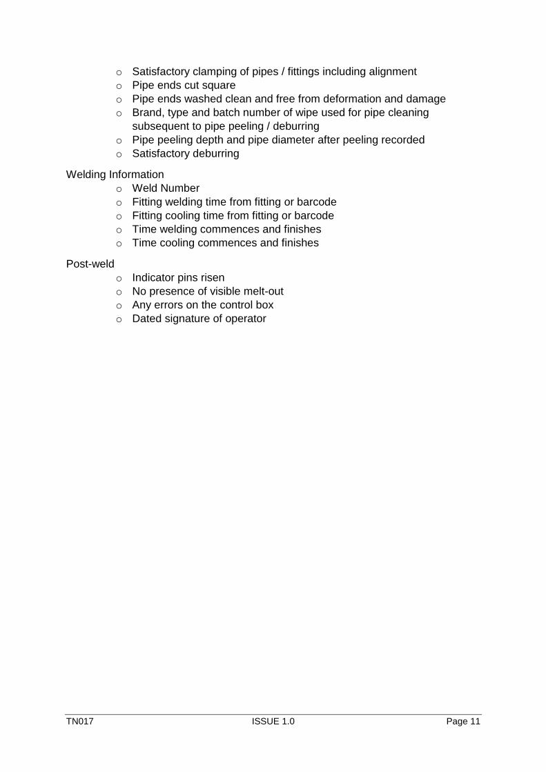
o Satisfactory clamping of pipes / fittings including alignment
o Pipe ends cut square
o Pipe ends washed clean and free from deformation and damage
o Brand, type and batch number of wipe used for pipe cleaning
subsequent to pipe peeling / deburring
o Pipe peeling depth and pipe diameter after peeling recorded
o Satisfactory deburring
Welding Information
o Weld Number
o Fitting welding time from fitting or barcode
o Fitting cooling time from fitting or barcode
o Time welding commences and finishes
o Time cooling commences and finishes
Post-weld
o Indicator pins risen
o No presence of visible melt-out
o Any errors on the control box
o Dated signature of operator


