NASA CONTRACTOR REPORT 1774.29 - Recommendations for Ground Effects Research for V/STOL and STOL Aircraft and Associated Equipment for Large Scale Testing R. E. Kuhn (BASA-CR- 177429) BEGUBBBICAZ3GIS POR CBCUlD 888-175LS EEEECPS RESE&BCB' ZOB V/SlrCL ALhD SPGL AffiCBAPT AND ASSOCIATED EQUIE&EB!Z FOP LUGE SCALE 'iESSfbiC (Kahn (Bicfrard E-)) 110 p Uaclas CSCL OlA G3/02 0125856 March 1986 CONTRACT NASP- 1 19 12 National Aeronautics and Space Administratiori https://ntrs.nasa.gov/search.jsp?R=19880008201 2018-06-14T01:05:15+00:00Z
Transcript
NASA CONTRACTOR REPORT 1774.29
-
Recommendations for Ground Effects Research for V/STOL and STOL Aircraft and Associated Equipment for Large Scale Testing
R. E. Kuhn
(BASA-CR- 177429) BEGUBBBICAZ3GIS POR CBCUlD 888-175LS EEEECPS RESE&BCB' ZOB V/SlrCL ALhD SPGL AffiCBAPT A N D ASSOCIATED EQUIE&EB!Z FOP L U G E SCALE 'iESSfbiC (Kahn (Bicfrard E-)) 110 p Uaclas
Planform angular mean diameter, ft Jet diameter, ft
Height above ground board, ft
Distance between blowing slots, ft
Distance downstream of blowing slot, ft Lift, lb
Mass flow from blowing BLC slots, slugs/sec Jet total pressure, lb/ft
Ambient pressure, lb/ft
Free stream dynamic pressure, lb/ft
Jet stream dynamic pressure, lb/ft
BLC blowing slot thickness, ft
Time, sec
Thrust, lb Inlet temperature rise, deg, F
Free stream velocity, ft/sec
Belt speed, ft/sec
Effective velocity ratio, Ve = Jqo/qj
Jet velocity, ft/sec
BLC blowing slot velocity, ft/sec
Weight flow from BLC blowing slots, lb/sec Longitudinal distance or distance ahead of jet impingement point, ft
Vertical distance, ft Angle of attack, deg
Downwash angle, deg
Boundary layer displacement thickness, ft
iii
SYMBOLS (Concluded)
Boundary layer momentum thickness, f t
Density of ambient a i r , l b s e c 2 / f t 4
Density of jet flow, l b s ec2 / f t4
iv
INTRODUCTION
The c o n t r a c t under which t h i s r epor t was prepared is p a r t of t he NASA Ames Research Center r e sea rch e f f o r t on the ground e f f e c t s a s s o c i a t e d wi th V/STOL and STOL opera t ion . Primary emphasis is on f u t u r e experimental programs i n t h e 40- by 80-, 80- by 120-foot wind tunnel test s e c t i o n s , and t h e Outdoor Aerodynamic Research F a c i l i t y (OARF) c o l l e c t i v e l y r e f e r r e d t o as t h e Nat iona l F u l l s c a l e Aerodynamics Complex (NFAC).
Task I of t h e p re sen t con t r ac t covered a review of t he then cu r ren t under- s t and ing of t h e e f f e c t s of ground proximity, an i d e n t i f i c a t i o n of t h e areas where a d d i t i o n a l r e sea rch was needed and an o u t l i n e of t h e experimental programs and test equipment needed. The Task I repor t is included as t h e leadoff paper i n t h e publ ished proceedings ( r e f . 1 ) of the I n t e r n a t i o n a l Workshop on V/STOL and STOL ground e f f e c t s he ld a t t h e NASA Ames Research Center a t t h e conclus ion of t he Task I e f f o r t .
The Task I1 e f f o r t covered conceptual des ign of the equipment needed f o r t h e 80- by 120-foot test s e c t i o n and the a s soc ia t ed outdoor s t a t i c test s t and f o r t he l a r g e scale s t u d i e s of ground proximity i d e n t i f i e d i n Task I and at t h e workshop. This f i n a l r epor t inc ludes a summary of t he r e s u l t s of t he workshop and the Task I e f f o r t and p resen t s the r e s u l t s of t he Task I1 e f f o r t and a s soc ia t ed recommendations.
2 BASIC FLOW FIELD
The development of equipment and t e s t i n g techniques f o r i n v e s t i g a t i n g t h e ground e f f e c t s of V/STOL a i r c r a f t must be based on t h e a v a i l a b l e unders tanding of t he flow phenomena involved. Our cu r ren t understanding of t he flow mecha- nisms involved i n hovering and i n t r a n s i t i o n i n and out of ground e f f e c t is d iscussed under s e v e r a l c a t e g o r i e s i n t h e main body of t h i s r epor t and i n more d e t a i l i n r e fe rence 1 . The paragraphs t h a t fo l low g ive a b r i e f overview i n an a t tempt t o put t h e flow mechanisms i n broad perspec t ive .
8
The bas i c flow f i e l d s a s soc ia t ed with hovering, t r a n s i t i o n and STOL opera- t i o n of j e t powered V/STOL a i r c r a f t are depic ted i n f i g u r e 2. induce fo rces and moments on t h e a i r c r a f t which must be known i n order t o make accu ra t e p r e d i c t i o n s of t h e performance and s t a b i l i t y and c o n t r o l c h a r a c t e r i s - t i c s of t he a i r c r a f t .
These flow f i e l d s #
When hovering out of ground e f f e c t (upper l e f t hand corner of f i g . 2 ) t h e j e t streams t h a t support t h e a i r c r a f t e n t r a i n a i r and induce s u c t i o n p res su res on the lower su r faces . These pressures produce a s m a l l download; u s u a l l y about 1 t o 2 percent o r less of t h e j e t t h r u s t . These downloads are small and t h e a v a i l a b l e empi r i ca l methods f o r e s t ima t ing them ( r e f . 2) are adequate.
As t h e hovering a i r c r a f t descends i n t o ground e f f e c t , t h e j e t stream impinges on t h e ground and forms a r a d i a l w a l l j e t flowing outward from t h e impingement poin t . This w a l l j e t a l s o e n t r a i n s a i r and s i g n i f i c a n t l y inc reases t h e induced s u c t i o n p res su res and t h e r e s u l t i n g down load as t h e c o n f i g u r a t i o n approaches the ground. There have been many i n v e s t i g a t i o n s of t h e j e t induced suckdown f o r s i n g l e j e t conf igu ra t ions , and while t h e b a s i c phenomena i s w e l l understood, t h e r e are s i g n i f i c a n t d i f f e r e n c e s i n t h e r e s u l t s ob ta ined by var ious i n v e s t i g a t o r s . These d i sc repanc ie s w i l l be d iscussed i n later s e c t i o n s .
With mul t ip l e j e t conf igu ra t ions the r a d i a l w a l l jets f lowing outward from t h e i r r e spec t ive impingement po in t s meet and form an up flow o r "fountain" . The impingement of t h e foun ta in on the a i r c r a f t produces an upload which u s u a l l y p a r t i a l l y o f f s e t s t he suckdown c rea t ed by the entrainment a c t i o n of t h e w a l l jets. Unfor tuna te ly , t h e foun ta in flow a l s o induces h igher s u c t i o n p res su res between t h e je ts and t h e founta ins . The mechanisms involved are poorly under- s tood and t h e p re sen t method f o r e s t ima t ing t h e j e t induced ground e f f e c t s on m u l t i p l e j e t conf igu ra t ions are inadequate.
I n t h e t r a n s i t i o n between hover and convent ional f l i g h t t h e r e are s e v e r a l f low mechanisms t h a t induce fo rces and moments on t h e a i r c r a f t . The flow i n t o t h e i n l e t produces an i n l e t momentum drag f o r c e and usua l ly a nose up p i t ch ing moment. The e x i t i n g j e t flow is d e f l e c t e d rearward by the f r e e stream and r o l l s up i n t o a p a i r of v o r t i c e s . These v o r t i c e s p lus the blockage and entrainment a c t i o n of t he je ts induce s u c t i o n p res su res behind and bes ide the j e t s and posi- t i v e pressures ahead of t he jets. The ne t e f f e c t f o r most j e t V/STOL configura- t i o n s is usua l ly a l o s s i n l i f t and a nose up p i t ch ing moment. However, i f t h e je ts are a t o r near t h e t r a i l i n g edge of t h e wing ( p a r t i c u l a r l y i f they have apprec iab le spanwise e x t e n t as i n a j e t f l a p c o n f i g u r a t i o n ) , they induce posi- t i v e l i f t and a nose down moment. The j e t wake s y s t e m a l s o induces s i g n i f i c a n t i nc reases i n the downwash a t t he t a i l .
3 In ground e f f e c t a t t r a n s i t i o n speeds (STOL o p e r a t i o n ) , a l l t h e above flow
phenomena are p r e s e n t , but modified by the presence of t h e ground. I n a d d i t i o n a ground vor tex is formed by the a c t i o n of t he f r e e stream i n opposing t h e w a l l j e t flowing forward from the impingement p o i n t ( s ) of t he f r o n t j e t ( s ) . This ground vor tex creates and de f ines the d u s t cloud produced when ope ra t ing over loose t e r r a i n , is one of t he mechanisms of hot gas i n g e s t i o n , and induces an a d d i t i o n a l l i f t loss and an a s soc ia t ed moment. Our knowledge of t h e f a c t o r s t h a t c o n t r o l t h e p o s i t i o n and s t r e n g t h , and, t h e r e f o r e , t h e e f f e c t s of t h e ground vor t ex are incomplete at t h i s t i m e .
Both t h e ground vor t ex and the foun ta in flow are involved i n hot gas re in- ges t ion . I n hover , t he foun ta in flow provides a d i r e c t pa th t o br ing hot gas ses i n t o the v i c i n i t y of t he i n l e t where they can be inhaled. The s e v e r i t y of t h i s p a r t of t he hot gas problem can be con t ro l l ed t o some e x t e n t by the placement of t h e i n l e t , by t h e arrangement of the je ts and by the use of s u i t a b l e flow d e f l e c t o r s . A t forward speed t h e ground vor t ex provides an a d d i t i o n a l pa th t o b r ing the hot gas i n the forward flowing w a l l j e t back t o t h e v i c i n i t y of t h e i n l e t . Our a b i l i t y t o des ign f o r minimum i n g e s t i o n is compromised by our l i m i t e d understanding of both t h e foun ta in flows and ground vor tex .
The fo l lowing s e c t i o n s w i l l h i g h l i g h t t he research needed i n each of t he above areas ( t h e Task I e f f o r t ) and b r i e f l y summarize t h e r e s u l t s of t h e Ground E f f e c t s Symposium. Later s e c t i o n s w i l l p resent t he conceptual des ign of t h e equipment recommended f o r ground e f f e c t s research i n the 80- by 120-foot t es t s e c t i o n and a s s o c i a t e d outdoor test s tand.
RESEARCH NEEDS
Single Jet Suckdown
The f i r s t d e f i n i t i v e work on j e t induced suckdown i n ground e f f e c t w a s done by Wyatt ( r e f . 3 ) . H e showed t h a t t he suckdown experienced on a wide range of s i z e s and shapes of p l a t e s by a s i n g l e j e t i s s u i n g through t h e p l a t e s could be estimated by the expression;
-2.3
A few years la ter H a l l used a 5-85 engine t o measure t h e j e t induced suck- down at l a r g e scale ( r e f . 4 ) . H i s r e s u l t s are i n good agreement wi th t h e es t i - mate based on Wyatt 's work and appeared t o i n d i c a t e t h a t any scale, o r real j e t , e f f e c t s were n e g l i g i b l e . However, t he small scale r e s u l t s of r e fe rence 5 i nd i - ca ted somewhat more suckdown than e i t h e r Wyatt 's o r H a l l ' s work.
Other small scale d a t a ( r e f s . 5-7) a l s o showed depa r tu re s from Wyatt 's and recent l a r g e scale tests by Chr i s t i ansen and Eshleman ( r e f . 8) show more suck- down than t h a t es t imated by Wyatt 's method ( f i g . 3 ) .
4 There are several factors that could contribute to these differences.
These include jet turbulence and temperature, exit velocity distribution, cross gusts in the room in which the tests were conducted or crosswinds in outdoor testing and the effects of ground board size. Few of the reports on jet suck- down give information on any of these factors. All of these and, perhaps others, need to be investigated.
It is doubtful that additional force tests could uncover the reasons for the differences in suckdown discussed above. What is needed are investigations to probe the fundamentals of the flow. Two investigations are recommended as follows :
1) The suckdown is caused by the lowered pressure under the planform due to the entrainment of ambient air into the wall jet flowing outward from the point where the jet impinges on the ground. Little is known about the effects of jet turbulence, pressure ratio, velocity distribution, etc. on the develop- ment of the wall jet and it's ability to entrain air. The investigation of these factors and their effects on the suckdown should have high priority.
1
2) There is limited evidence (ref. 9) that testing in a room of inade- quate size can cause excessive suckdown. Estimates presented in the first paper of reference 1 indicate that cross gusts (or cross winds in outdoor testing) of only 1 to 2 percent of the jet velocity can produce increases in suckdown equal to the differences observed between various suckdown measurements (fig. 3 , for example). An investigation of the effects of the size of test chamber on suck- down is needed.
Both of these investigations are justified and described in more detail in the first paper in reference 1.
Multiple Jet Suckdown and Fountain Effects
When the wall jets flowing outward from the impingement points of two adjacent jets meet, a fan shaped upwash or "fountain" is formed between the jets as shown in figure 4 . If there are more than two jets a fan shaped fountain is formed between each pair and a fountain "core" is formed at the center where the fountain fans meet. The impingement of these fountain flows on the configura- tion produces an upload which acts to partially offset the suckdown induced by the outward flowing wall jets.
The result is usually, but not always, a reduction in suckdown. As shown in figure 5 , Lummus (ref. l o ) , measured the suckdown for two configurations with equal planform to jet area ratio and found for the configuration shown in figure 5 that the suckdown for the twin jet configuration was greater than for the single jet configuration. Apparently there is an additional suckdown that more than equals the lift force produced by the fountain between the two jets.
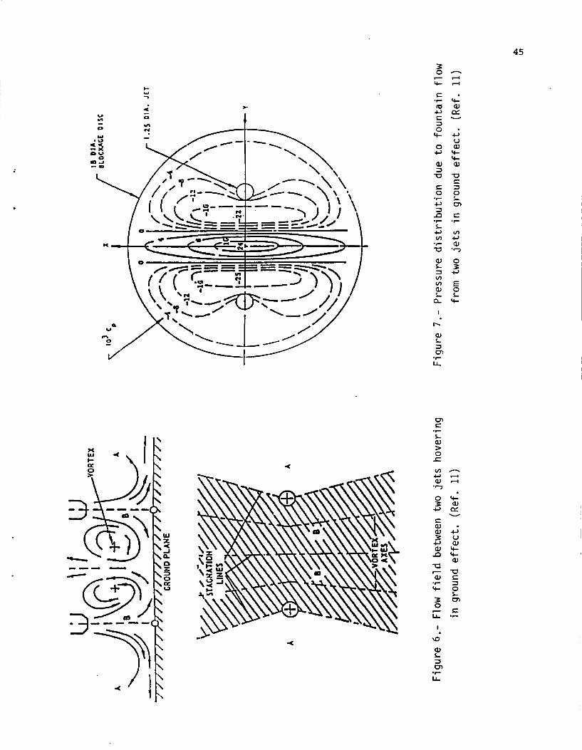
The probable cause of this additional suckdown is shown in figures 6 and 7 (from ref. 11). A vortex-like flow is formed between the fountain flow and each of the adjacent jets and these vortex-like flows induce additional suction pres- sures between the jets and the positive pressure region produced by the fountain flow (fig. 7 ) . and induced lift are presented in references 12 to 18.
Additional data and analysis of the multiple jet fountain flow
5 Attempts t o develop methods f o r p r e d i c t i n g t h e mul t ip l e j e t ground e f f e c t s
have been made i n r e fe rences 13 and 14 but t h e s e methods are l i m i t e d t o configu- r a t i o n s similar t o those on which these empir ica l methods are based. A b e t t e r understanding of t h e vor tex- l ike flows developed between t h e upward f lowing foun ta in and the downward flowing jets along wi th the a s s o c i a t e d p res su re d i s t r i b u t i o n d a t a is needed t o provide t h e b a s i s f o r a more widely a p p l i c a b l e method f o r e s t ima t ing mul t ip l e j e t ground e f f e c t s .
For "real" a i r c r a f t con f igu ra t ions the e f f e c t s of body and lower s u r f a c e contour and of s t r a k e s o r " l i f t improvement devices" (LID'S) i n s t a l l e d t o "capture" more of t he foun ta in flow must a l s o be considered. Also t he f o r e and a f t d i s t r i b u t i o n of s u r f a c e area on which the s u c t i o n and l i f t i n g p res su res act is not u sua l ly symmetrical about the a i r c r a f t c e n t e r of g r a v i t y and usua l ly produces a ground e f f e c t induced p i t ch ing moment.
A l l of t hese e f f e c t s must be recognized and considered but i t is recom- mended t h a t t he f i r s t p r i o r i t y with r e spec t t o m u l t i p l e j e t ground e f f e c t s should be given t o ob ta in ing a b e t t e r understanding of t h e flow f i e l d between t h e je ts and t h e i r a s soc ia t ed foun ta in flows and the p re s su res these flows induce.
Ground Vortex in SMlL Operation
I n STOL ope ra t ion t h e w a l l j e t flowing forward from t h e impingement p o i n t of t he f r o n t j e t is opposed by the f r e e stream and r o l l e d up i n t o a horseshoe shaped ground vor t ex as depic ted i n f i g u r e 8. When ope ra t ing over loose t e r r a i n t h i s ground vor t ex creates and de f ines t h e dus t cloud t h a t can reduce v i s i b i l i t y and damage engines . It is a l s o one of t h e primary mechanisms of hot gas inges- t i o n and can induce a l i f t l o s s and moments on t h e a i r c r a f t .
A ground vor t ex type of flow is a l s o a s soc ia t ed wi th j e t f l a p configura- t i ons . W i l l i a m s e t a l . , i n r e f . 19, found a t rapped vo r t ex under a high a s p e c t r a t i o f u l l span blown f l a p conf igu ra t ion i n ground e f f e c t ( f i g . 9).
The ground vor tex is a l s o a problem when t h r u s t r e v e r s e r s are opera ted i n ground e f f e c t . The forward d e f l e c t i o n of t he j e t t o produce a drag component of t h e t h r u s t p r o j e c t s t h e ground vor t ex f u r t h e r forward and i n c r e a s e s i t s s t r eng th . This aggrava tes t h e hot gas i n g e s t i o n problem and can a l s o l ead t o s i g n i f i c a n t l i f t loss and moments as shown by J o s h i i n r e fe rence 20 ( f i g . 10).
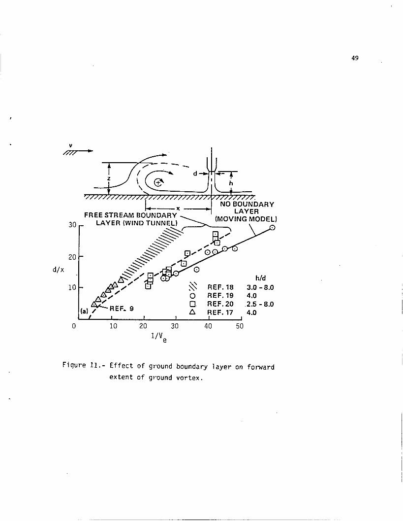
The ground vor t ex a s soc ia t ed with jet impingement has been s t u d i e d i n s e v e r a l i n v e s t i g a t i o n s ( r e f s . 9 and 21-24). These f i v e s t u d i e s show a wide v a r i a t i o n i n t h e forward p r o j e c t i o n of t he ground vor tex flow f i e l d ( f i g . 11). Some of t h i s v a r i a t i o n may be due t o the manner i n which the forward edge of t h e flow f i e l d w a s def ined o r i t may be due t o t h e e f f e c t s of j e t p re s su re r a t i o o r flow q u a l i t y . However, i t is bel ieved t h a t t he boundary l a y e r between the f r e e stream and the ground board ahead of t he ground vor tex may be t h e p r i n c i p a l f a c t o r .
With a boundary l a y e r , t he high v e l o c i t i e s i n t h e w a l l j e t (which are very c l o s e t o t h e ground) can pene t r a t e f u r t h e r a g a i n s t t he r e l a t i v e l y lower ve loc i - ties i n the f r e e stream boundary l a y e r than they would be a b l e t o p e n e t r a t e a g a i n s t t he f u l l f r e e stream ve loc i ty . The i n v e s t i g a t i o n of r e fe rence 21 set out t o s imula t e the boundary l a y e r of atmospheric winds and, t h u s , had a t h i c k
6 boundary l aye r . It is seen t o have t h e most forward p e n e t r a t i o n ( f i g . 11). Reference 22, on t h e o t h e r hand, used t h e moving model technique and, t h u s , t h e r e was no boundary l aye r . It shows t h e smallest pene t r a t ion . L i t t l e is known about t he boundary l a y e r i n t h e o t h e r i n v e s t i g a t i o n s o t h e r than t h a t t h e i n v e s t i g a t i o n of r e fe rence 24 was made a t r e l a t i v e l y low Reynolds number and, t h u s , probably had a r e l a t i v e l y t h i c k boundary l a y e r .
Another f a c t o r may be t h e e f f e c t of t h e v e l o c i t y of t he model over t h e ground. With the moving-model technique ( a s i n t h e a c t u a l s i t u a t i o n of t h e a i r c r a f t moving over t h e ground) t h e scrubbing d rag of t he w a l l j e t on t h e ground th i ckens t h e boundary l a y e r between t h e w a l l j e t and t h e ground, reduces t h e momentum of t h e w a l l j e t and reduces i ts a b i l i t y t o p e n e t r a t e upstream. With the f i x e d model over a f i x e d ground t h i s more r ap id r educ t ion i n wall-jet energy is not experienced.
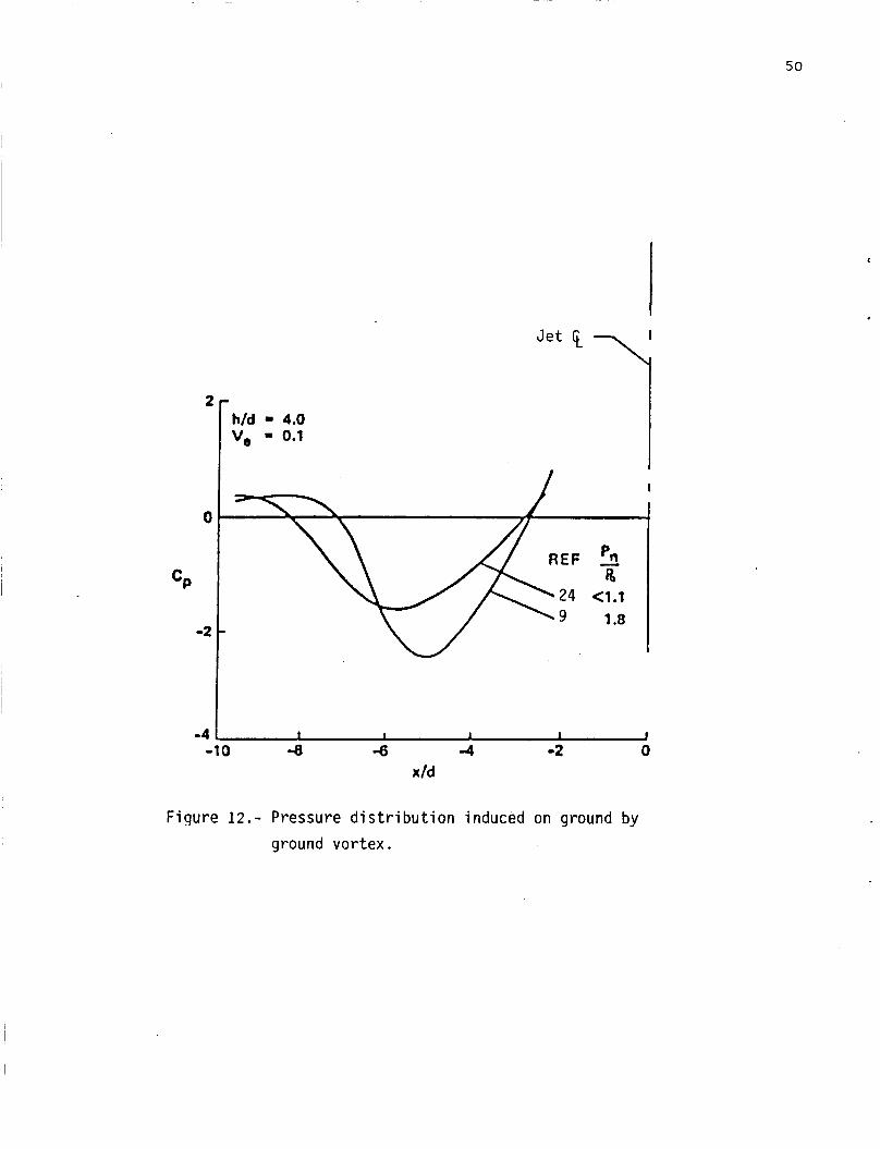
The s t r e n g t h of t he ground vor t ex a l s o appears t o be d i f f e r e n t i n d i f f e r e n t i n v e s t i g a t i o n s . Figure 1 2 shows t h e p re s su re d i s t r i b u t i o n s measured on t h e ground board under t h e ground v o r t i c e s of two s t u d i e s . The d a t a of r e fe rence 9 show a g r e a t e r nega t ive p re s su re than the d a t a of r e fe rence 24 i n d i c a t i n g a g r e a t e r v o r t e x s t r e n g t h . The reason f o r t h e d i f f e r e n c e is unc lea r but may be a s s o c i a t e d with t h e r a t h e r l a r g e d i f f e r e n c e i n j e t p re s su re r a t i o i n t h e two i n v e s t i g a t i o n s .
Because of t h e importance of t he ground vor t ex t o STOL ope ra t ions and t o hot-gas i n g e s t i o n (d i scussed i n a la te r s e c t i o n ) , a b e t t e r understanding of t h e f a c t o r s t h a t determine t h e l o c a t i o n and s t r e n g t h of t he ground v o r t e x is needed. The primary need a t t h i s t i m e is t o determine t h e e f f e c t s of j e t - p r e s s u r e r a t i o , t h e ground board boundary l a y e r , and the movement r e l a t i v e t o t h e ground.
Jet Flap Ground Effects
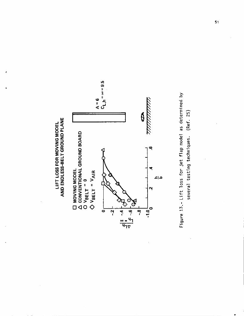
It has been recognized f o r a long t i m e t h a t t h e c o r r e c t ground e f f e c t s on j e t f l a p models cannot be determined i n tests over f i x e d ground board. Turner ( r e f . 25) showed t h a t t h e l i f t l o s s e s measured over a f i x e d ground board were much l a r g e r than those measured with a moving model and t h a t t h e use of a moving-belt ground gave t h e same r e s u l t s as t h e moving model tests ( f i g . 13) . Flow v i s u a l i z a t i o n s t u d i e s by Werle ( r e f . 26) show t h e l a r g e d i f f e r e n c e i n t h e flow f i e l d under t h e model w i th f i x e d and moving ground ( f i g . 14) .
The use of a moving-belt ground board i n t h e 40- by 80- and 80- by 120-foot F i r s t t h e development, i n s t a l - t e s t s e c t i o n s appears i m p r a c t i c a l on two counts.
l a t i o n , and maintenance of a l a r g e enough b e l t system would be e x c e s s i v e l y complex, t i m e consuming, and c o s t l y . Second, t h e exhaust temperatures of t h e j e t engines used i n wind tunne l models would be d i f f i c u l t t o accommodate. The use of blowing boundary l a y e r c o n t r o l on the ground board t o r e p l a c e t h e b e l t has been suggested. I n cons ide r ing t h e design of such a ground board system t h e f u n c t i o n t h a t t h e moving b e l t s e rves must be f u l l y considered.
It has u s u a l l y been assumed t h a t t h e belt did i t ' s j o b j u s t by e l i m i n a t i n g the boundary l a y e r between the f r e e stream and the ground board ahead of t h e model pos i t i on . Hackett ( r e f . 27) has pointed out t h a t t he belt has an addi- t i o n a l d i r e c t e f f e c t on t h e vo r t ex flow system under the model ( f i g . 15). Because t h e f l u i d i n con tac t with the belt has t o move with t h e b e l t a "nega- t i v e " boundary l a y e r is c r e a t e d i n t h e region of t h e v o r t e x system t h a t acts
7 directly on, and retards the vortex flow. Any attempt to develop a blowing BLC ground board to replace the belt must recognize and duplicate this effect of the belt.
Because most of the early work on the ground effects of jet flap configura- tions was done on configurations that developed very high lift coefficients out of ground effect and suffered a loss in lift In ground effect, it is sometimes assumed that all jet flap configurations will experience a lift loss in ground proximity. Stevens, in paper number 14 of reference 1, has presented flight test data on the QSRA that show a lift increase in ground proximity (fig. 16) and it is sometimes assumed that this indicates a disagreement between flight and wind tunnel data. However, Campbell (ref. 28) shows that the effect of ground proximity on jet flap configurations is highly configuration dependent. At moderate lift coefficients a lift gain similar to that experienced on the QSRA can be experienced on unswept partial-span jet-flap configurations (fig. 17).
There is no fundamental reason why wind tunnel tests should not be able to duplicate ground effects experienced in flight, provided the ground is properly simulated. The carefully derived QSRA flight data on ground effects provide a unique data base with which to evaluate wind tunnel technique. constructed model of the QSRA configuration should be built for use in evaluat- ing and developing the ground simulation technique planned for the large tunnels.
A carefully
Downwash at the Tail
Lift is produced by deflecting the flow around the aircraft downward. The high lifts produced by powered lift aircraft are associated with high def lec- tions of the flow and, therefore, high downwash angles behind the aircraft in the region of the tail. The presence of the ground interrupts this downward flow of air and, therefore, the downwash at the tail would be expected to reduce as the ground is approached.
Unfortunately, there is little data available from which the effects of ground proximity on the downwash can be determined. Reference 9 attempted to correlate the effects of ground proximity for jet flap configurations (fig. 18) and jet lift configurations (fig. 19) and to develop expressions for estimating the observed effects.
Additional data on a wider variety of configurations is needed to determine the extent of applicability of the methods presented in reference 9 and it is recommended that additional data in this area be obtained by seizing every opportunity presented by tests of complete configuration to obtain additional downwash data in and out of ground effect.
Hot Gas Ingestion
The ingestion of hot gasses into the engine inlet depends on the flow field under and around the aircraft. Three basic mechanisms are involved. In far field ingestion (fig. 2 0 ) , the wall jet flowing outward from the impingement point slows as it moves outward and eventually separates from the ground under the influence of buoyancy. The entrainment action of the wall jet induces a downward and inward flow that carries warm air back to the vicinity of the
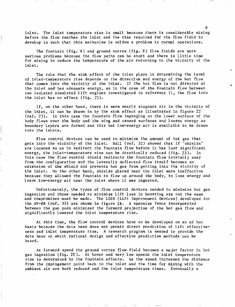
8 in le t . The i n l e t temperature r ise i s small because t h e r e i s cons iderable mixing before the flow reaches the i n l e t and the t i m e r equ i r ed f o r t he flow f i e l d t o develop i s such that t h i s mechanism i s seldom a problem i n normal ope ra t ions .
The foun ta in ( f i g . 4 ) and ground vor t ex ( f i g . 8 ) f low f i e l d s are more s e r i o u s problems because the flow paths can be s h o r t and t h e r e i s l i t t l e t i m e f o r mixing t o reduce t h e temperature of t h e a i r r e t u r n i n g t o the v i c i n i t y of t he in le t .
The r o l e t h a t t he s ink e f f e c t of the i n l e t p lays i n determining t h e l e v e l of in le t - tempera ture rise depends on t h e d i r e c t i o n and energy of the ho t f low t h a t comes i n t o the v i c i n i t y of the i n l e t . I f t he ho t f low i s not d i r e c t e d a t t h e inlet and has adequate energy, as i n t h e case of the foun ta in flow between two i s o l a t e d s imula ted l i f t engines i n v e s t i g a t e d i n r e fe rence 11, t he flow i n t o t h e i n l e t has no e f f e c t ( f i g . 21) .
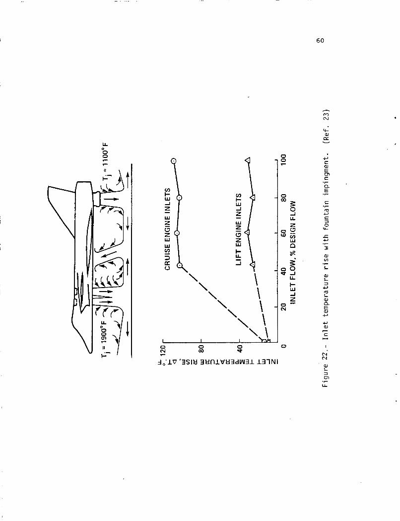
I f , on t h e o t h e r hand, t h e r e i s w a r m n e a r l y s t agnan t a i r i n the v i c i n i t y of t he i n l e t , i t can be drawn i n by the s i n k e f f e c t as i l l u s t r a t e d i n f i g u r e 22 ( r e f . 2 3 ) . I n t h i s case t h e foun ta in f low impinging on the lower s u r f a c e of t h e body f lows over the body and the wing and canard su r faces and l o o s e s energy as boundary l a y e r s are formed and t h i s hot low-energy a i r i s a v a i l a b l e t o be drawn i n t o t h e inlets.
Flow con t ro l devices can be used t o minimize the amount of ho t gas t h a t g e t s i n t o the v i c i n i t y of t he i n l e t . H a l l ( r e f . 32) showed t h a t i f " s h i e l d s " are l o c a t e d so as t o r e d i r e c t t he foun ta in flow before i t has l o s t s i g n i f i c a n t energy, t h e in le t - tempera ture rise can be d r a s t i c a l l y reduced ( f i g . 2 3 ) . In t h i s case the f low con t ro l s h i e l d r e d i r e c t s t he foun ta in f low l a t e r a l l y away from the conf igu ra t ion and the l a t e r a l l y d e f l e c t e d f low i t s e l f becomes an ex tens ion of t he s h i e l d and prevents ho t gas from g e t t i n g i n t o the v i c i n i t y of t h e in le t . On t h e o t h e r hand, s h i e l d s placed near t h e i n l e t were i n e f f e c t i v e because they al lowed the foun ta in t o flow up around the body, t o l o s e energy and l e a v e low-energy a i r near t h e i n l e t where i t was inges ted .
Unfor tuna te ly , t h e types of flow con t ro l devices needed t o minimize hot gas i n g e s t i o n and those needed t o minimize l i f t l o s s i n hovering are not t h e same and compromises must be made. The LIDS ( L i f t Improvement Devices) developed f o r t he AV-8B ( r e f . 33) are shown i n f i g u r e 2 4 . A spanwise fence inco rpora t ed between t h e gun pods minimized t h e forward p r o j e c t i o n of t he hot gas flow and s i g n i f i c a n t l y lowered the i n l e t temperature rise.
A t t h i s t i m e , t he flow con t ro l devices have t o be developed on an ad hoc b a s i s because t h e d a t a base does no t p e r m i t d i r e c t p r e d i c t i o n of l i f t e f f e c t i v e - ness and in le t temperature rise. A r e sea rch program i s needed t o provide the da ta base on which r a t i o n a l des ign and e f f e c t i v e p red ic t ion methods can be based.
A t forward speed the ground vor tex flow f i e l d becomes a major f a c t o r i n hot gas i n g e s t i o n ( f i g . 2 5 ) . A t hover and very low speeds the i n l e t temperature r ise i s determined by the foun ta in e f f e c t s . A s t he speed inc reases t h e d i s t a n c e from the impingement poin t back t o the i n l e t and t h e t i m e f o r mixing wi th the ambient a i r are both reduced and the i n l e t temperature rises. Eventual ly a
9 speed i s reached a t which t h e ground vor tex flow f i e l d i s blown behind o r under the i n l e t and the i n l e t temperature rise goes t o zero.
The maximum in l e t temperature rise f o r t h i s conf igu ra t ion ( r e f . 34) has been found t o be i n v e r s e l y propor t iona l t o the square of t he r a t i o of i n l e t he ight (measured from t h e lowes t po in t of t he i n l e t ) t o t h e diameter of t h e f r o n t j e t ( r i g h t s i d e of f i g , 2 5 ) . i n - l i ne je t conf igu ra t ions . With side-by-side conf igu ra t ions a foun ta in flow i s p ro jec t ed upward and forward between the jets and t h e i n l e t temperature rise i s much g r e a t e r . Addit ional da ta on hot gas i n g e s t i o n are presented i n r e fe rences 35 - 39.
This f i n d i n g a p p l i e s only t o s i n g l e j e t or
rn To avoid i n g e s t i o n t h e inlet must be ahead of or above t h e ho t gas cloud
c rea t ed by t h e ground-vortex system. Unfortunately, t h e r e are wide v a r i a t i o n s i n t h e data on t h e l o c a t i o n of t he ground vor tex as was d i scussed above ( f i g , 11). Those i n v e s t i g a t i o n s t h a t a t tempted t o determine the depth of t h e f low f i e l d i n d i c a t e d t h e depth t o be about ha l f of the forward p ro jec t ion . A s wi th t h e forward p r o j e c t i o n , Abbott ' s d a t a from the moving model tests showed t h e l ea s t depth and the Schwantes s tudy , which at tempted t o simulate t h e deep boundary l a y e r s of a tmospheric winds, showed t h e g r e a t e s t depth ( f i g . 2 6 ) . These anomalies i n t h e d a t a on t h e s i z e of the ground vor t ex flow f i e l d need t o be reso lved before a s a t i s f a c t o r y method f o r e s t ima t ing the speed t o avoid hot gas i n g e s t i o n can be developed.
It i s recommended t h a t t h e i n v e s t i g a t i o n of t he e f f e c t s of je t p re s su re r a t i o and ground board boundary l a y e r be designed t o provide f o r ex tens ion t o inc lude t h e e f f e c t s on hot gas i n g e s t i o n of i n l e t p o s i t i o n , s i n g l e and side-by- s i d e je ts , and bodies o r su r faces between the jets.
WORKSHOP RESULTS
A 2-day workshop was held a t the NASA Ames Research Center on August 20 and 21, 1985, t o review the f i n d i n g s and recommendations presented i n the Phase I r e p o r t (Paper no. 1 i n ref. l ) , summarized above, and t o ob ta in i n d u s t r y views on the r e sea rch needed on the e f f e c t s of ground proximity. a t t h a t workshop are publ ished i n r e fe rence 1 .
The p a p e r s presented
The papers presented g e n e r a l l y augmented t h e review presented i n t h e Phase I r e p o r t but also poin ted out s eve ra l areas which were not adequate ly covered. jet p re s su re r a t i o and shape on the development of the w a l l j e t as reviewed i n r e fe rence 40 are of cons iderable s i g n i f i c a n c e i n ana lyz ing t h e suckdown and foun ta in e f f e c t s i n ground e f f e c t .
I n p a r t i c u l a r t h e work of Kotansky and a s s o c i a t e s on t h e e f f e c t s of
The work by Kro thapa l l i and S a r i p a l l i (paper 2 i n r e f . 1) on the foun ta in flow between j e t s poin ted out t he h igh turbulence l e v e l s of the f low i n the foun ta in which results i n r a p i d mixing wi th the surrounding a i r and very r ap id spreading.
The papers presented by Rizk and Childs ( p a p e r s 3 and 4 i n ref. 1) on numerical s imula t ion of w a l l je ts and je t induced i n t e r a c t i o n s i n d i c a t e t h a t
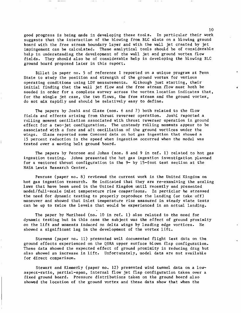
10 good progress i s being made i n developing these too l s . I n particular t h e i r work sugges ts that t h e i n t e r a c t i o n of t h e blowing from BLC s l o t s on a blowing ground board wi th t h e f r e e stream boundary l a y e r and wi th t h e wall j e t c r e a t e d by je t impingement can be ca l cu la t ed . These a n a l y t i c a l tools should be of cons ide rab le he lp i n understanding t h e development of t he w a l l je t and ground vor t ex f low f i e l d s . ground board proposed la te r i n t h i s r epor t .
They should also be of cons iderable he lp i n developing the blowing BLC
B i l l e t i n paper no. 5 of r e fe rence 1 r epor t ed on a unique program a t Penn S t a t e t o s tudy t h e p o s i t i o n and s t r e n g t h of t he ground vor t ex f o r va r ious ope ra t ing cond i t ions us ing LDV measurements. Although j u s t s t a r t i n g , t h e i r i n i t i a l f i nd ing t h a t t he wall jet flow and the f r e e stream flow must both be seeded i n o rde r f o r a complete survey ac ross the vo r t ex l o c a t i o n i n d i c a t e s t h a t , f o r t h e s i n g l e j e t case , t he two f lows, the f r e e stream and the ground vor t ex , do not mix r a p i d l y and should be r e l a t i v e l y easy t o def ine.
The papers by J o s h i and Glaze (nos. 6 and 7 ) both r e l a t e d t o the f low f i e l d s and e f f e c t s a r i s i n g from t h r u s t r e v e r s e r opera t ion . J o s h i r epor t ed a r o l l i n g moment o s c i l l a t i o n a s s o c i a t e d wi th t h r u s t r e v e r s e r ope ra t ion i n ground e f f e c t f o r a two-jet conf igura t ion . The unsteady r o l l i n g moments a p p e a r t o be a s s o c i a t e d wi th a f o r e and a f t o s c i l l a t i o n of t he ground v o r t i c e s under t h e wings. Glaze repor ted some Concord data on hot gas i n g e s t i o n t h a t showed a 15 percent r educ t ion i n t h e speed when i n g e s t i o n occurred when the model w a s t e s t e d over a moving b e l t ground board.
The papers by Penrose and Johns (nos. 8 and 9 i n r e f . 1 ) r e l a t e d t o ho t gas i n g e s t i o n t e s t i n g . Johns presented t h e hot gas i n g e s t i o n i n v e s t i g a t i o n planned f o r a vec tored t h r u s t conf igu ra t ion i n the 9- by 15-foot test s e c t i o n a t t h e NASA L e w i s Research Center.
Penrose (paper no. 8 ) reviewed t h e c u r r e n t work i n t h e United Kingdom on h o t gas i n g e s t i o n research . H e i nd ica t ed that they are re-examining t h e s c a l i n g l a w s t h a t have been used i n the United Kingdom u n t i l r e c e n t l y and presented model/fuLl-scale i n l e t temperature rise comparisons. I n par t ic la r he s t r e s s e d t h e need f o r dynamic t e s t i n g t o proper ly reproduce t h e l a n d i n g ( o r t a k e - o f f ) maneuver and showed t h a t i n l e t temperature rise measured i n s t eady s ta te tests can be up t o twice t h e l e v e l s t h a t would be experienced i n an a c t u a l landing .
The paper by Murihead (no. 10 i n r e f . 1 ) a l s o r e l a t e d t o the need f o r dynamic t e s t i n g but i n t h i s case the s u b j e c t was the e f f e c t of ground proximity on t h e l i f t and moments induced on d e l t a wings by l e a d i n g edge v o r t i c e s . H e showed a s i g n i f i c a n t l a g i n the development 'of t he vo r t ex l i f t .
Stevens (paper no. 11) presented w e l l documented f l i g h t tes t da ta on t h e ground e f f e c t s experienced on t h e QSRA upper s u r f a c e blown f l a p conf igu ra t ion . These d a t a showed the expected e f f e c t of ground proximity i n reducing drag but a l s o showed an i n c r e a s e i n l i f t . Unfor tuna te ly , model da t a are no t a v a i l a b l e f o r d i r e c t comparison.
Stewart and Kimmerly (paper no. 12) presented wind tunnel da ta on a low- a s p e c t - r a t i o , pa r t i a l - span , i n t e r n a l f low j e t f l a p conf igu ra t ion taken over a f ixed ground board. Pressure d i s t r i b u t i o n s taken on the ground board a l s o showed the l o c a t i o n of t he ground vor t ex and these data show that when t h e
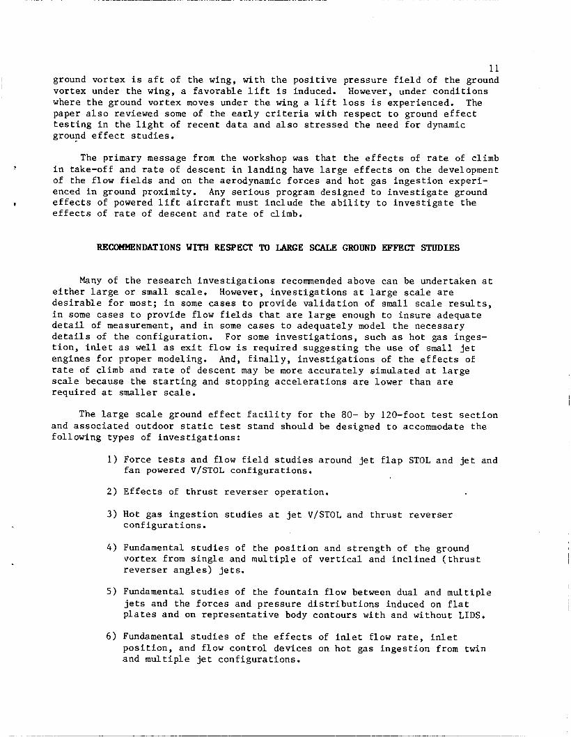
11 I ground vor tex i s a f t of t he wing, wi th t h e p o s i t i v e p re s su re f i e l d of t h e ground I vor tex under the wing, a favorable l i f t i s induced. However, under cond i t ions
where t h e ground vor t ex moves under t h e wing a l i f t loss i s experienced. The paper a l s o reviewed some of t he e a r l y c r i t e r i a wi th respect t o ground e f f e c t t e s t i n g i n t h e l i g h t of r ecen t d a t a and a l s o s t r e s s e d t h e need f o r dynamic ground e f f e c t s t u d i e s .
The primary message from the workshop was that the e f f e c t s of rate of climb i n take-off and ra te of descent i n l and ing have l a r g e e f f e c t s on t h e development of t he f low f i e l d s and on the aerodynamic f o r c e s and ho t gas i n g e s t i o n exper i - enced i n ground proximity. Any s e r i o u s program designed t o i n v e s t i g a t e ground
e f f e c t s of rate of descent and rate of climb. I e f f e c t s of powered l i f t a i r c r a f t must inc lude the a b i l i t y t o i n v e s t i g a t e t h e
RECOMMENDATIONS WITH RESPECT TO LARGE SCALE GROUND EFFECT STUDIES
Many of t h e r e sea rch i n v e s t i g a t i o n s recommended above can be undertaken a t e i t h e r l a r g e o r small scale. However, i n v e s t i g a t i o n s a t l a r g e scale are d e s i r a b l e f o r most; i n some cases t o provide v a l i d a t i o n of small scale results, i n some cases t o provide flow f i e l d s that are l a r g e enough t o i n s u r e adequate d e t a i l of measurement, and i n some cases t o adequate ly model t h e necessary d e t a i l s of t he conf igu ra t ion . For some i n v e s t i g a t i o n s , such as hot gas inges- t i o n , i n l e t as w e l l as ex i t flow i s r equ i r ed sugges t ing t h e use of s m a l l j e t engines f o r proper modeling. And, f i n a l l y , i n v e s t i g a t i o n s of t he e f f e c t s of ra te of climb and ra te of descent may be more accurately s imulated a t l a r g e scale because t h e s t a r t i n g and s topping a c c e l e r a t i o n s are lower than are r equ i r ed a t smaller scale.
The l a r g e scale ground e f f e c t f a c i l i t y f o r t he 80- by 120-foot tes t s e c t i o n and a s s o c i a t e d outdoor s t a t i c tes t s tand should be designed t o accommodate t h e fo l lowing types of i n v e s t i g a t i o n s :
1) Force tests and flow f i e l d s t u d i e s around j e t f l a p STOL and j e t and f a n powered V/STOL conf igura t ions .
2 ) E f f e c t s of t h r u s t r e v e r s e r opera t ion .
3 ) Hot gas i n g e s t i o n s t u d i e s a t j e t V/STOL and t h r u s t r e v e r s e r conf igu ra t ions .
4 ) Fundamental s t u d i e s of t he p o s i t i o n and s t r e n g t h of t h e ground vor tex from s i n g l e and m u l t i p l e of v e r t i c a l and i n c l i n e d ( t h r u s t r e v e r s e r a n g l e s ) jets.
5) Fundamental s t u d i e s of the foun ta in flow between dual and m u l t i p l e je ts and the f o r c e s and p res su re d i s t r i b u t i o n s induced on f l a t p la tes and on r e p r e s e n t a t i v e body contours wi th and without LIDS.
6 ) Fundamental s t u d i e s of the e f f e c t s of i n l e t f low ra te , i n l e t p o s i t i o n , and flow con t ro l devices on ho t gas i n g e s t i o n from twin and m u l t i p l e jet conf igura t ions .
12
Providing the ability to conduct these types of investigations will require .
developing special equipment in the following three areas:
1) Equipment to simulate the propulsion systems.
2) A model support system with the capability to simulate the climb and descent rates of typical operations.
3) A ground board that insures proper simulation of the flow under and around the model.
Discussion of the requirements for the equipment in each of these three areas and recommendations for their development are presented in the following sections.
PROPULSION SPSTW SIMULATION
!hall Jet Engines
For some investigations, tests of the full scale configuration with the proposed engines may be feasible, but more often suitable engines are not avail- able. Either the proposed engines are not available in the early stages of the aircraft development or, for other reasons, tests of a subscale model of the proposed configuration are desired. In these cases alternative engines may be substituted but it is usually not possible to maintain the external aerodynamic lines (available engines are relatively larger than the proposed engines would be) or it is not possible to match the exit area, temperature, and pressure ratio.
Remotely Powered Models
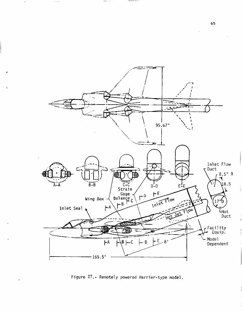
In an attempt to circumvent the problems of matching the nozzle exit condi- tions and, at the same time maintaining the external aerodynamic lines of the configuration, the possibility of using externally mounted jet engines and duct- ing the hot exhaust flow into the model from one engine and ducting the inlet flow out of the model to another engine was examined. The problems of using this approach are illustrated in figure 27 .
In this study it was assumed that the model of a Harrier-type configuration would be powered by two J-97 engines, one supplying the hot exhaust flow to the four nozzles and the other powering the inlet. On the Harrier the front and rear nozzles operate at different temperatures and pressure ratios. With one engine providing the flow to all four nozzles, it is not possible to match the pressure ratio and temperature of both the front and rear nozzles. Instead the total nozzle area was matched to that required by the J-97 engine. This resulted in an approximately one-third scale model.
I
The primary problem encountered with the remotely powered model approach is that most of the fuselage volume is taken up with the ducting required to get the exit flow to the nozzles. There is no space left for the inlet flow duct and this duct must be taken out the top of the model. The result is that the
13 top of the model and the tail assembly is violated. The resulting model could be used for some ground effect and hot gas ingestion studies but only at zero sideslip. Investigations of lateral directional characteristics or downwash at the tail are impossible. A separate model powered by other means would be required for these tests. This approach, therefore, appears impractical for tests of specific models.
While the remotely powered model approach does not appear practical for specific models, it is attractive for some fundamental studies which will be discussed in a later section.
Hot Ejectors
Ejectors have been used to simulate jet engines in the past, particularly for small scale studies, but full representation of the jet engine has not been attained. In particular the jet temprature has not been reproduced and the inlet mass flow is not fully duplicated.
The possibility of adding a burner to provide the hot exhaust has been suggested and discussed with the .two firms that have had extensive experience providing ejectors for jet engine simulation in wind tunnel tests. Both agree it is possible. Two approaches can be made: one using a remotely mounted burner with heated high pressure air piped to the primary nozzles, and the other using a burner with each ejector unit downstream of the mixing region (fig. 28) .
The first approach minimizes the size of the simulator that must be installed in the model but presents the problem of ducting very hot high pres- sure air into the model. The second approach reduces the ducting problem to one that is routinely handled in powered model testing but increases the size of the unit that must be contained within the model lines. It is not obvious which approach is best and it is recommended that a two phase study of the development of hot ejectors suitable for use in powered model testing be undertaken.
For this approach it is assumed that the high pressure air ( ~ 4 0 lb/sec at 3000 psi) available at the 40- by 80-foot test section will be available at the 80- by 120-foot test section also. The study should assume that four simulator units are to be used in a model of a PCB equipped Harrier-type configuration (similar to that shown in figures 27 and 28) with provision for separate control (thrust, pressure ratio, and temperature) of the front and rear jets. The study should be aimed at achieving the following characteristics in each of the four units:
Thrust .................... up to .................... 1200 lb. Jet exit diameter ......... nominal ..................... 6 in. Jet exit pressure ratio ... up to ......................... 3.5 Jet exit temperature ...... up to ...................... 1200°F Drive air ................. less than ... 10 lb/sec at 3000 psi Inlet flow ................ maximize
It is recognized that the attainment of full inlet mass flow with an ejector based simulator is not possible. However, the limited hot gas ingestion data available indicates that full inlet mass flow is not required to determine the inlet temperature rise (fig. 2 2 ) . The primary objective of the development
14 program should be t o o b t a i n as much i n l e t flow as p o s s i b l e while a t t a i n i n g f u l l s imu la t ion of t h e j e t e x i t flow.
DYNAMIC RIG FOB THE 80- BY 120-woT TEST SECTION AND OUTWOB STATIC TEST STAND
The Need
The Phase I r e p o r t placed primary emphasis on ground e f f e c t s i n s t e a d y s t a t e operat ion. One of t h e main recommendations t h a t c a m e out of t h e workshop w a s t h a t p rov i s ion should be made f o r i n v e s t i g a t i n g t h e e f f e c t s of rate of descent and rate of climb during landing and t akeof f . There are a number of s t u d i e s t h a t show t h a t t h e r e are t i m e dependent a s p e c t s t o the development of t h e flow f i e l d s i n ground proximity t h a t s i g n i f i c a n t l y a f f e c t t he e f f e c t s on t h e a i r c r a f t .
Turner, i n r e f . 25, showed t h a t t h e r e is a l a g i n the development of t h e l i f t l o s s experienced by a f u l l span j e t f l a p c o n f i g u r a t i o n i n ground e f f e c t ( f i g . 29) . The model was mounted from the c a r r i a g e of a hydrodynamic towing tank (with t h e water removed) and moved t h e model over a f i x e d ground board. board could be drooped t o simulate a 10-degree landing approach. The data show t h a t t h e r e is a l a g i n t h e development of t h e flow f i e l d t h a t r e s u l t s i n about a 3-chord l e n g t h l a g i n t h e development of t he l i f t loss.
The tests were made us ing t h e moving model technique.
The l ead ing edge of t h e ground
S i m i l a r l y , Stevens and Wingrove ( r e f . 41) p re sen t d a t a from a landing approach and waveoff t h a t shows a h y s t e r e s i s i n t h e l i f t i n c r e a s e due t o ground e f f e c t on t h e augmenter wing a i r c r a f t ( f i g . 30). The l i f t i n c r e a s e s as t h e ground is approached, but t h i s i n c r e a s e is eroded during t h e waveoff.
A d i f f e r e n t type of t i m e dependency is presented i n f i g u r e 31. McLemore, i n r e f . 42, p r e s e n t s a series of photographs showing t h e development of a hot gas cloud. The model was powered by a 5-85 engine wi th t h e i n l e t on t h e top of t h e model. The e x i t is a t a he igh t of two j e t diameters above t h e 50-foot diameter (about 50 j e t d i ame te r s ) conc re t e pad. A d e f l e c t o r w a s a t t a c h e d t o t h e e x i t so t h a t t h e engine could be s t a r t e d and brought up t o speed wi th t h e exhaust d e f l e c t e d a f t t o avoid inges t ion . A t t i m e zero t h e d e f l e c t o r was removed t o b r ing t h e e x h a u s t , t o t h e v e r t i c a l . Simultaneously, at t i m e zero, a pu l se of smoke w a s i n j e c t e d i n t o t h e upwind s i d e of t h e j e t and photographs were taken a t 0.2-second i n t e r v a l s t o record t h e development of t he cloud.
About 1 second w a s r equ i r ed f o r t he cloud t o develop t o t h e po in t where t h e smoke is brought back t o t h e v i c i n i t y of t h e i n l e t . This ag rees wi th t h e temperature d a t a which i n d i c a t e d t h a t t he temperature began t o rise about 1 second a f t e r t h e d e f l e c t o r w a s removed.
Although t h e s e tests were run a t f i x e d h e i g h t , i t is expected t h a t a s i m i - l a r de lay may be experienced i n a landing descent . 6 f e e t per second, t h e onse t of hot gas i n g e s t i o n would be delayed and i n i t i a l i n g e s t i o n may occur a t a he igh t 3 t o 6 f e e t lower than would be i n d i c a t e d by s t eady s ta te i n g e s t i o n tests. The con jec tu re presented he re needs t o be v e r i - f i e d by a c t u a l tes ts , but i t does suggest t h e need f o r t h e a b i l i t y t o s imula t e
A t a s i n k speed of 3 t o
I
15 t h e takeoff and l and ing climb and descent rates t o o b t a i n a r e l i a b l e i n d i c a t i o n of t h e s u s c e p t a b i l i t y of a conf igu ra t ion t o hot gas i n g e s t i o n .
Penrose, i n paper no. 11 of r e fe rence 1, presented a comparison of t h e i n l e t temperature rise as a f u n c t i o n of headwind v e l o c i t y from cons tan t height-- 15-second hover tests and those measured i n l and ing descen t s ( f i g . 3 2 ) . The moving model tests show only about half t he l e v e l of i n l e t temperature rise measured i n the l and ing descents .
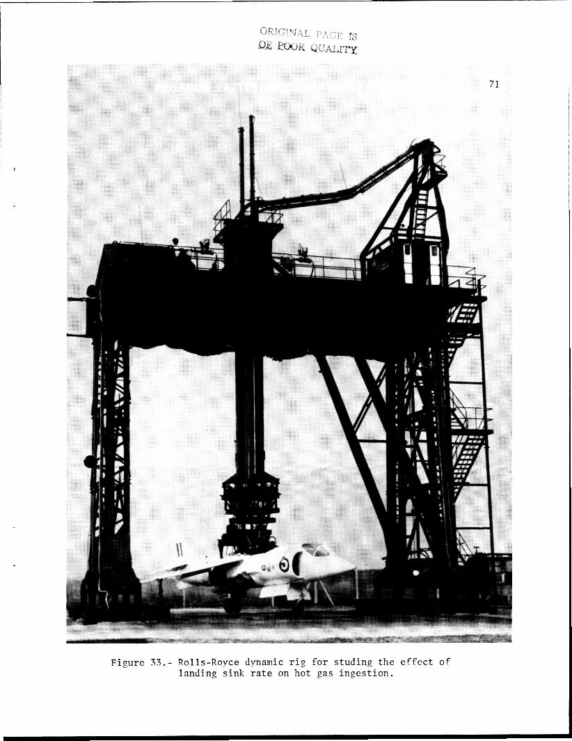
As a r e s u l t of t he f avorab le r e s u l t s obtained wi th moving model r i g s i n t h e United Kingdom, and i n view of t he high e x i t temperatures thought p o s s i b l e wi th t h e planned PCB ve r s ions of t he engine used i n t h e Harriers, Ro l l s Royce has developed a f u l l scale dynamic r i g ( f i g . 33) f o r hot gas i n g e s t i o n i n v e s t i g a t i o n s .
Also the probable problems a s s o c i a t e d with t h r u s t r e v e r s e r o p e r a t i o n on f i g h t e r c o n f i g u r a t i o n s i n landing t h a t have been pointed out by the work of J o s h i (paper no. 9 i n r e f . 1) and Glaze (paper no. 10 i n r e f . 1) have l e d t o a s p e c i a l test program as repor t ed by both J o s h i and Kimmerly (papers 9 and 15 i n r e f . 1) . Center ( f i g . 34) t o move t h e model over a ground board with a s l o p i n g ramp t o s imula t e the landing approach as Turner d id i n r e f . 25.
The program w i l l use t h e Vortex F a c i l i t y a t t h e Langley Research
The Concept
A l l of t h e above obse rva t ions c l e a r l y i n d i c a t e t h e need f o r a model support system f o r ground e f f e c t t e s t i n g i n the 80- by 120-foot t unne l and t h e a s s o c i a t e d outdoor s t a t i c test f a c i l i t y t h a t can s imula t e takeoff and l and ing rates of climb and descent as w e l l as support t h e model a t cons t an t he igh t s .
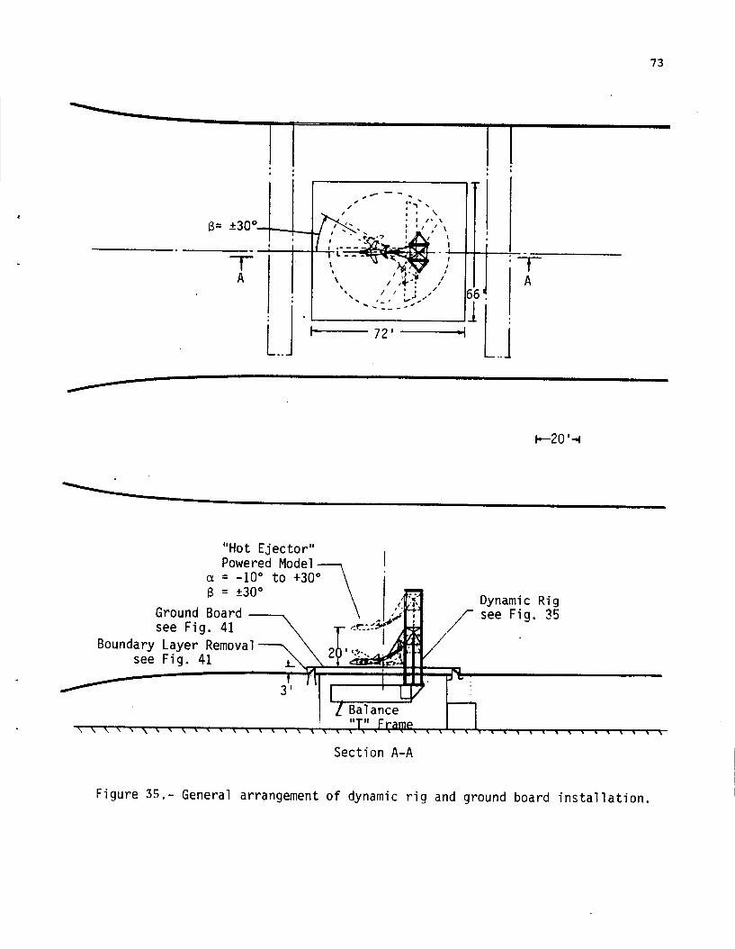
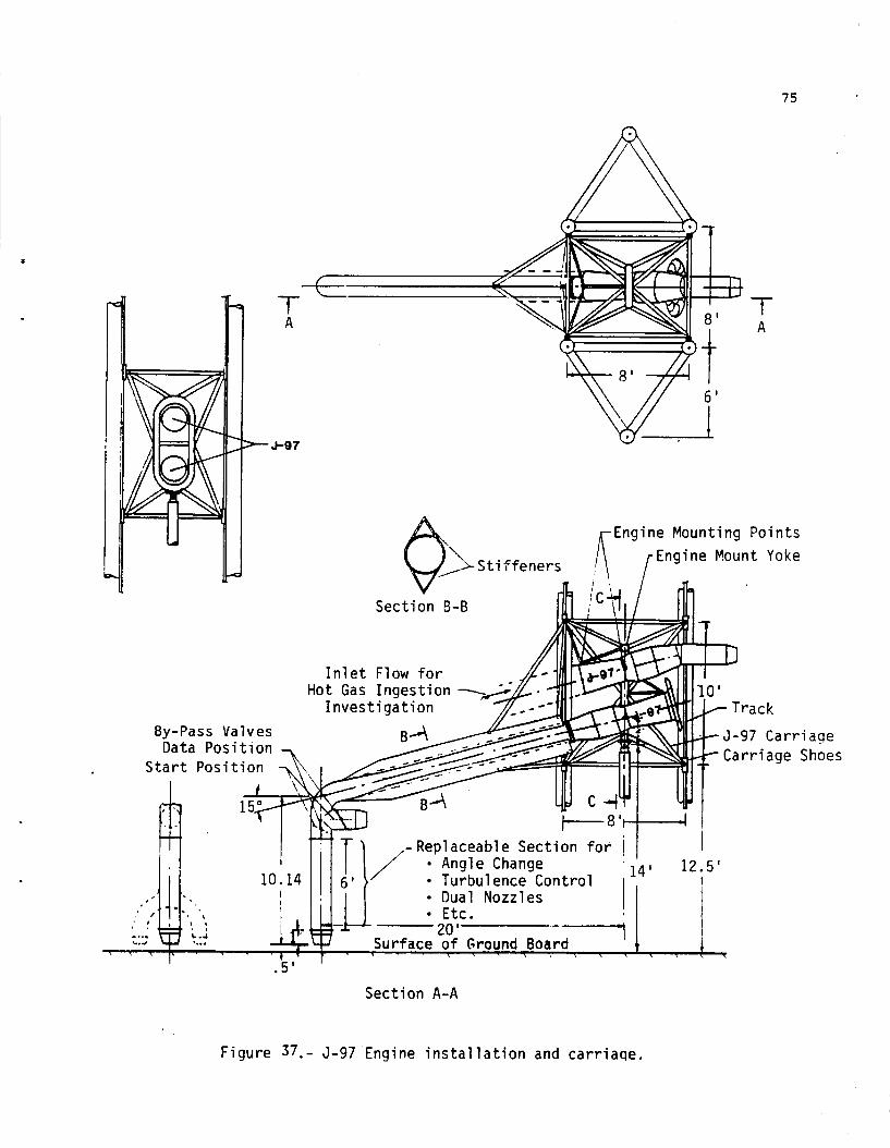
The type of model support system recommended is i l l u s t r a t e d i n f i g u r e s 35 and 36. Figure 35 shows the gene ra l arrangement of t h e i n s t a l l a t i o n i n the 80- by 120-foot test s e c t i o n . Two d i f f e r e n t c a r r i a g e s w i l l be required. Figure 36 shows t h e c a r r i a g e f o r tests of complete models suppor t ing a j e t f l a p configura- t i on . Figure 37 shows t h e c a r r i a g e and J-97 engine i n s t a l l a t i o n f o r fundamental s t u d i e s of w a l l jet and ground vor t ex development s t u d i e s as w e l l as hot gas i n g e s t i o n i n v e s t i g a t i o n s . The c a r r i a g e s are supported and d r iven v e r t i c a l l y by a h y d r a u l i c c y l i n d e r which can be c o n t r o l l e d and programmed t o provide v a r i o u s climb and descent p r o f i l e s as i l l u s t r a t e d i n f i g u r e s 38 t o 49 .
The complete dynamic r i g i s mounted on t h e "T" frame of t he balance system i n the 80- by 120-foot test s e c t i o n (which' is r o t a t e d 180 degrees from i t s normal p o s i t i o n ) t o provide support and 530-degree yaw c a p a b i l i t y f o r t h e dynamic r i g ( f i g . 3 6 ) . i n s t a l l a t i o n , t he e n t i r e f l o o r t u r n t a b l e is removed. The 56-foot diameter ho le opened when t h e f l o o r t u r n t a b l e is removed is , of cour se , covered by the ground board which is used i n conjunct ion with t h e dynamic r i g .
Rather than modify t h e f l o o r t u r n t a b l e t o p e r m i t t h i s
Although t h e e n t i r e dynamic r i g is mounted on t h e balance system ( f i g . 3 6 ) , t h i s balance system cannot be used t o measure t h e model f o r c e s and moments because it does not have t h e response rates requ i r ed and because a l l t h e a i r loads on t h e c a r r i a g e and t ack support s t r u c t u r e w i l l a l s o be f e l t by t h i s balance system. Ins t ead t h e models w i l l be mounted on i n t e r n a l s t r a i n gage balances .
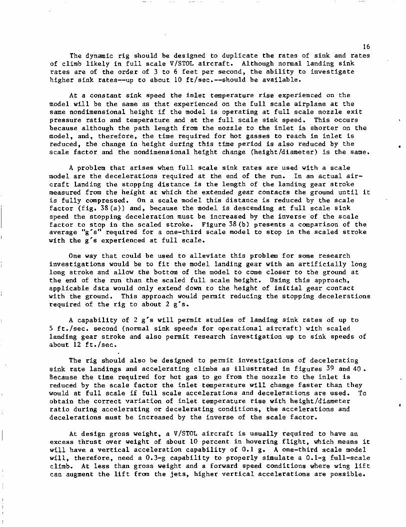
16 The dynamic r i g should be designed t o d u p l i c a t e t h e rates of s i n k and rates
of climb l i k e l y i n f u l l scale V/STOL a i r c r a f t . Although normal landing s i n k rates are of t h e o r d e r of 3 t o 6 f e e t p e r second, t h e a b i l i t y t o i n v e s t i g a t e h ighe r s i n k rates--up t o about 10 ft/sec.--should be a v a i l a b l e .
1
A t a cons t an t s i n k speed the i n l e t temperature rise experienced on t h e model w i l l be t h e same as t h a t experienced on t h e f u l l s c a l e a i r p l a n e a t t h e same nondimensional he igh t i f t h e model is ope ra t ing a t f u l l scale nozz le e x i t p r e s s u r e r a t i o and temperature and a t t h e f u l l scale s i n k speed. This occurs because al though t h e pa th l eng th from t h e nozz le t o t h e i n l e t is s h o r t e r on t h e model, and, t h e r e f o r e , t h e t i m e r equ i r ed f o r hot gas ses t o reach i n i n l e t is reduced, t h e change in he igh t du r ing t h i s time period is a l s o reduced by t h e I
scale f a c t o r and t h e nondimensional he igh t change (he igh t /d i ame te r ) is t h e same.
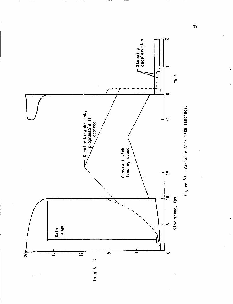
A problem t h a t arises when f u l l scale s i n k rates are used wi th a scale model are t h e d e c e l e r a t i o n s r equ i r ed a t the end of t h e run. I n an a c t u a l air- c r a f t landing t h e s topping d i s t a n c e is t h e l e n g t h of t h e l and ing gear s t r o k e measured from t h e he igh t a t which t h e extended gea r c o n t a c t s t h e ground u n t i l i t i s f u l l y compressed. On a scale model t h i s d i s t a n c e is reduced by t h e scale f a c t o r ( f i g . 3 8 ( a ) ) and, because t h e model is descending a t f u l l scale s i n k speed t h e s topping d e c e l e r a t i o n must b e inc reased by t h e i n v e r s e of t h e scale f a c t o r t o s t o p i n t h e sca l ed s t roke . F igu re 38 (b) p r e s e n t s a comparison of t h e average "g's'' r equ i r ed f o r a one-third scale model t o s t o p i n t h e s c a l e d s t r o k e wi th t h e g's experienced a t f u l l scale.
One way t h a t could be used t o a l l e v i a t e t h i s problem f o r some resea rch i n v e s t i g a t i o n s would be t o f i t t h e model landing gea r with an a r t i f i c i a l l y long long s t r o k e and al low the bottom of t h e model t o come c l o s e r t o t h e ground a t t h e end of t h e run t han t h e sca l ed f u l l scale height . Using t h i s approach, a p p l i c a b l e d a t a would only extend down t o t h e h e i g h t of i n i t i a l gea r c o n t a c t w i th the ground. T h i s approach would permit reducing t h e s topp ing d e c e l e r a t i o n s r equ i r ed of t h e r i g t o about 2 g's.
A c a p a b i l i t y of 2 g's w i l l permit s t u d i e s of landing s i n k rates of up t o 5 f t . / s e c . second (normal s i n k speeds f o r o p e r a t i o n a l a i r c r a f t ) w i t h s c a l e d landing g e a r s t r o k e and a l s o permit r e sea rch i n v e s t i g a t i o n up t o s i n k speeds of about 1 2 f t . / s e c .
The r i g should a l s o be designed t o p e r m i t i n v e s t i g a t i o n s of d e c e l e r a t i n g s i n k rate l and ings and a c c e l e r a t i n g climbs as i l l u s t r a t e d i n f i g u r e s 39 and 4 0 . Because t h e t i m e required f o r hot gas t o go from t h e nozz le t o t h e i n l e t is reduced by t h e scale f a c t o r t h e i n l e t temperature w i l l change faster than they would a t f u l l scale i f f u l l scale a c c e l e r a t i o n s and d e c e l e r a t i o n s are used. To o b t a i n t h e c o r r e c t v a r i a t i o n of i n l e t temperature rise with he igh t /d i ame te r r a t i o during a c c e l e r a t i n g o r d e c e l e r a t i n g cond i t ions , t h e a c c e l e r a t i o n s and d e c e l e r a t i o n s must be inc reased by t h e i n v e r s e of t h e scale f a c t o r .
A t de s ign g r o s s weight, a V/STOL a i r c r a f t is u s u a l l y required t o have an excess t h r u s t over weight of about 10 pe rcen t i n hovering f l i g h t , which means i t w i l l have a v e r t i c a l a c c e l e r a t i o n c a p a b i l i t y of 0.1 g. A one-third scale model w i l l , t h e r e f o r e , need a 0.3-g c a p a b i l i t y t o p rope r ly s imula t e a 0. l-g f u l l - s c a l e climb. A t less than g r o s s weight and a forward speed cond i t ions where wing l i f t can augment t h e l i f t from t h e jets, h ighe r v e r t i c a l a c c e l e r a t i o n s are poss ib l e .
17 It is suggested t h a t t he r i g should be capable of producing up t o 1.0 g upward a c c e l e r a t i o n .
Requirements
The gene ra l conf igu ra t ion and p r i n c i p a l dimensions of t h e dynamic r i g and i t s two c a r r i a g e s are shown i n f i g u r e s 35-37. The dynamic r i g should be designed t o have a v e r t i c a l t r a v e l of about 20 f e e t and t o p o s i t i o n and hold t h e model a t any d e s i r e d he ight . Vertical t r a v e l rates of 0-15 f t / s e c should be provided. A yaw c a p a b i l i t y of k30 degrees should be provided by mounting t h e r i g on t h e p re sen t balance system. And an ang le of a t t a c k d r i v e system capable of -10 t o +30 degrees angle of a t t a c k should be designed i n t o t h e complete model ca r r i age . I n o rde r t o minimize the loads on and d e f l e c t i o n of t he c a r r i a g e , t r a c k s , and suppor t s t r u c t u r e , special e f f o r t w i l l be r equ i r ed t o minimize t h e weight of t he model and ca r r i ages .
The c a r r i a g e s , t r a c k s , and support s t r u c t u r e should be designed so t h a t t he d e f l e c t i o n of t h e model c e n t e r of g r a v i t y should not exceed 0.1 in . p e r 1000 l b s of loads i n any d i r e c t i o n . For t h e maximum t h r u s t of t he J-97 engine , t h i s t r a n s l a t e s i n t o a p o s s i b l e e r r o r i n p o s i t i o n of t h e nozzle c e n t e r of only about 5 percent of t h e je t nozzle diameter.
Outdoor Static T e s t Stand
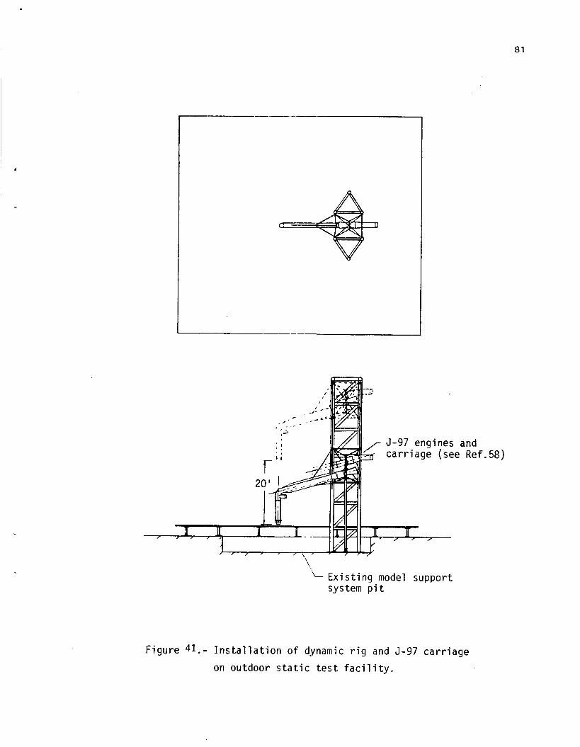
The dynamic r i g should a l s o be designed f o r use on the outdoor s t a t i c tes t s t and as depic ted i n f i g u r e 41. This w i l l r e q u i r e t h a t t h e hydrau l i c system t h a t d r i v e s and c o n t r o l s t he v e r t i c a l motion w i l l have t o be p o r t a b l e o r dup l i - ca ted a t t h e outdoor f a c i l i t y .
Alternate Concept
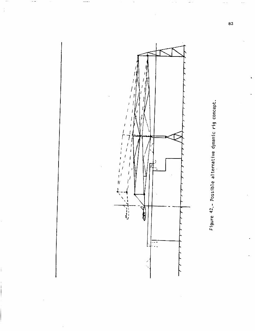
The a l t e r n a t e concept employing a "4-bar l inkage" arrangement ( f i g . 4 2 ) was considered i n t h e i n i t i a l p a r t of t h e p re sen t s tudy. It had t h e advantage of avoid ing the aerodynamic i n t e r f e r e n c e t h a t may arise i f t h e suppor t s t r u c t u r e behind t h e model i n t h e recommended conf igu ra t ion becomes too l a rge . However, it is more difficult to provide for y a w tests, some fore and aft movement of the model i s a s s o c i a t e d with v e r t i c a l motion causing a s l i g h t e r r o r i n e f f e c t i v e forward v e l o c i t y and the suppor t ing s t r u c t u r e becomes excess ive ly l a r g e , heavy, and d i f f i c u l t t o i n s t a l l and remove from t h e tunnel when i t is not being used.
Developpent
The problems t o be solved i n developing t h e proposed r i g w i l l i nc lude o b t a i n i n g smooth and r epea tab le motion and p o s i t i o n i n g , minimizing the weight of t h e model and c a r r i a g e t o minimize loads on and d e f l e c t i o n s of t he model, as w e l l as minimizing d r i v e power requirements r e s u l t i n g from t h e s t a r t i n g and s topping g ' s a t t he beginning and end of each run.
A two-step development process is recommended. The a c t u a l d e t a i l des ign and cons t ruc t ion ( s t e p 2) should be preceded by a pre l iminary des ign and eva lua t ion s tudy t o more c l e a r l y de f ine the conf igura t ion . This p re l imina ry des ign e f f o r t should include:
18 1) Preliminary design of representative models for test of the
proposed rig. The design process should be carried far enough to determine the likely minimum weight (including the propulsion system and the internal balance) that can be attained without excessive cost while maintaining structural integrity. Three models are recommended:
a) A model of the QSRA configuration. To provide wind tunnel data for comparison with the available flight data.
b) A model of the YAV-8B configuration. To provide wind tunnel data for comparison with flight data.
c) A J-97 powered nozzle/inlet rig for fundamental studies of flow fields and hot gas ingestion.
2) Preliminary design of two carriages. One for support of the speci- fic models and one supporting the J-97 engines (fig. 3 7 ) for funa- mental studies. The designs should be carried far enough to deter- mine the likely minimum weight while minimizing model deflection and extraneous motion.
3) Preliminary design of the vertical tracks and structure that support the carriage and model to insure sufficient stiffness and minimize unwanted motion of the model.
4 ) Choice of the hydraulic cylinder to drive the carriage and choice and design of the related power supply and control equipment.
5) Preliminary design of the umbilical chord that contains the instru- mentation and control lines to the model and the fuel and control lines to the J-97 engines.
The output of this preliminary design effort should be a revised design concept and requirements and specifications for the final design and construc- tion contract.
The Need
It has been recognized for a long time that the correct ground effects on jet flap models cannot be determined in tests over fixed ground board. Turner (ref. 25) showed that the lift losses measured over a fixed ground board were much larger than those measured with a moving model and that the use of a moving-belt ground gave the same results as the moving model tests (fig. 13).
The use of a moving-belt ground board in the 40- by 80- and 80- by 120-foot test sections appears impractical on two counts. First the development, installation, and maintenance of a large enough belt system would be excessively complex, time consuming, and costly; and second, the exhaust temperatures of the jet engines used in wind tunnel models would be difficult to accommodate. The
1 9 use of blowing boundary l a y e r c o n t r o l on t h e ground board t o replace t h e b e l t is suggested.
The Concept
The gene ra l arrangement of t h e proposed ground board is shown i n f i g u r e 4 3 . An i n l e t i s provided a t t h e l ead ing edge of t he board t o remove t h e boundary l a y e r on t h e tunne l f l o o r and m u l t i p l e blowing s l o t s are provided t o r e p l a c e t h e energy l o s t i n t h e boundary l a y e r t h a t b u i l d s up between s l o t s on t h e board. A i r is l e t i n a t t h e t r a i l i n g edge of t h e board t o f i l l t h e wake t h a t would develop behind t h e r a i s e d ground board.
The boundary l a y e r removal system a t the l ead ing edge of t h e board must r ep lace the energy l o s s i n t h e boundary l a y e r on t h e tunne l f l o o r and raise t h e s t a t i c p res su re from the test s e c t i o n p res su re t o atmospheric p re s su re . Prel iminary a n a l y s i s i n d i c a t e s t h a t 12-200 hp, 140,000 cfm blowers w i l l be required. Figure 44 p r e s e n t s t h e performance map of a commercially a v a i l a b l e blower t h a t c l o s e l y matches t h e s e requirements.
The volume of air flow requ i r ed by the mul t i - s lo t BLC system on the s u r f a c e of t h e ground board is considerably less than t h a t involved a t t h e l ead ing edge but t h e p r e s s u r e r a t i o r equ i r ed w i l l be higher because t h e v e l o c i t y from each s l o t w i l l have t o be two t o fou r t i m e s t he f r e e stream v e l o c i t y . Prel iminary a n a l y s i s i n d i c a t e s t h a t 2-600 hp blowers w i l l probably be required. A more complete d i s c u s s i o n of t h e mul t i - s lo t BLC concept, r a t i o n a l e , and t h e develop- ment program requ i r ed is presented i n t h e fol lowing s e c t i o n .
No power w i l l be needed t o provide the flow requ i r ed a t t h e t r a i l i n g edge of t he ground board. The 80- by 120-foot test s e c t i o n o p e r a t e s a t n e a r l y atmospheric t o t a l p re s su re ; t h e r e f o r e , t h e s ta t ic p r e s s u r e i n t h e t es t s e c t i o n is below atmospheric and w i l l draw a i r i n t o f i l l i n t h e volume behind t h e ground board i f a reasonably low l o s s flow path is provided.
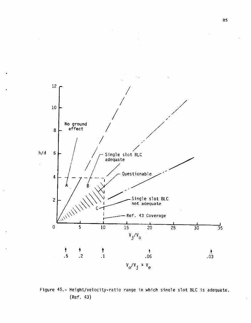
The p o s s i b i l i t y of u s ing blowing BLC on t h e ground board t o s u b s t i t u t e f o r t h e moving ground was i n v e s t i g a t e d i n r e fe rence 4 3 . It w a s found t h a t f o r je t flap configurations, a single blowing slot could be used to replace the moving ground i f it were p rope r ly placed with r e spec t t o t h e p re s su re d i s t r i b u t i o n induced on t h e ground by t h e model.
However, t he r e s u l t s obtained with a l i f t i n g j e t model were less encourag- ing. As shown i n f i g u r e 45 t h e r e were no ground e f f e c t s i n r eg ion A (low j e t v e l o c i t i e s and high o p e r a t i n g h e i g h t s ) and the s i n g l e s l o t blowing system w a s adequate i n region B. However, i n region C (low h e i g h t s and high j e t v e l o c i t i e s ) , t h e s i n g l e blowing s l o t was not adequate. This is t h e r eg ion where s t r o n g ground v o r t e x flows are encountered and where much of t h e hot gas inges- t i o n r e s e a r c h w i l l be concentrated ( f i g . 2 6 ) . I f a blowing BLC ground board can be made t o work i t w i l l have t o have m u l t i p l e and probably very c l o s e l y spaced blowing s l o t s .
Analysis of Requirements
I n o r d e r t o produce t h e c o r r e c t aerodynamic e f f e c t s on t h e ground v o r t e x system and f o r hot gas i n g e s t i o n r e sea rch , i t w i l l be necessary t o c o r r e c t l y reproduce t h e ground vor t ex flow f i e l d t h a t i s found i n a c t u a l f l i g h t (and ove r
20 a b e l t i n wind tunnel tests, f i g . 46 >. The moving ground ( b e l t ) has two e f f e c t s :
1) It e l i m i n a t e s t h e boundary l a y e r between the f r e e stream and t h e ground board t h a t would al low the w a l l j e t from the model t o p e n e t r a t e f u r t h e r ahead than i t would i f i t were opposed by t h e f u l l f r e e stream ve loc i ty .
t 2 ) The a i r a t the b e l t su r f ace must move wi th it . This causes a scrubbing a c t i o n t h a t reduces the momentum of t h e w a l l j e t i n t h e same way the w a l l j e t from a moving a i r c r a f t is eroded by the ground su r face . 8
Both of t hese e f f e c t s act t o reduce the forward pene t r a t ion of t h e w a l l j e t and move the ground vor tex c l o s e r t o the impingement poin t ( f i g . 4 6 ) . A mul t ip l e s l o t BLC ground boad must reproduce both e f f e c t s .
&mentum ReplacePent
I n order ' t o achieve an e f f e c t i v e "zero boundary l a y e r " s i t u a t i o n ahead of t h e model the blowing s l o t s must provide the momentum t o replace t h e f r e e stream momentum ( f r i c t i o n drag loss ) . A uniform v e l o c i t y d i s t r i b u t i o n is n o t achieved as i l l u s t r a t e d for a s i n g l e s l o t case i n f i g . 47 ( r e f . 4 4 ) but i f m u l t i p l e s l o t s a r e used t h e d e f i c i e n c i e s and overages i n v e l o c i t y can be kept very c l o s e t o t h e su r f ace.
A rough estimate of the s l o t th ickness ( s ) and mass flow (m) requi red can be made by the s i m p l i f i e d a n a l y s i s given below:
The blowing momentum must replace the f r e e stream momentum l o s t ( f r i c t i o n drag , Cf) over the d i s t a n c e 1 .
21 c, = Cf
where Cf is t h e s k i n f r i c t i o n c o e f f i c i e n t (from r e f . 45 f o r example). C, i s t h e blowing momentum c o e f f i c i e n t given by:
2 psbV
’ PV b2 2 0
P 2 c =
and b is the span of t h e blowing s l o t .
Therefore , t h e th i ckness of t he blowing s l o t requi red i s ,
A
v 2 2- v
s = Fc
0
and t h e mass flow requi red per f o o t of blowing span i s ,
These estimates are f o r a ne t momentum l o s s of zero a t t h e blowing s l o t . There are a d d i t i o n a l l o s s e s downstream of the s l o t and i f t he average loss over t h e board is t o be zero the blowing requi red w i l l be somewhat g r e a t e r . 48 presen t s a comparison of estimates by t h e above express ions wi th the d a t a from re fe rence 4 4 . I n o rde r t o r ep lace t h e momentum l o s s i n t h e boundary l a y e r at a distance of 200 slot thicknesses downstream of the slot the slot thickness and mass flow used were about twice those es t imated by t h e above s i m p l i f i e d a n a l y s i s .
F igure
Single Slot Blowing for Ground Simulation
The s l o t t h i ckness and mass flow requi red f o r t h e s i n g l e s l o t blowing system f o r ground s imula t ion proposed i n r e fe rence 46 are compared i n f i g u r e 49 with estimates by t h e above method f o r e s t ima t ing t h e blowing requi red f o r momentum replacement. The order-of-magnitude d i f f e r e n c e i n t h e r e s u l t s , and t h e dependence of t h e blowing requi red f o r ground s imula t ion on j e t p res su re r a t i o , suggest t h a t , f o r a s i n g l e s l o t system, t h e blowing requi red t o s imula t e t h e e f f e c t of t h e b e l t on t h e w a l l j e t flowing forward from the model may be consid- e r a b l y d i f f e r e n t than t h a t requi red f o r momentum replacement i n t h e f r e e stream boundary l a y e r .
The cond i t ions i n t h e w a l l j e t , a t zero f r e e stream v e l o c i t y , wi th the b e l t running are i l l u s t r a t e d a t t h e top of f i g u r e 50. b e l t moves wi th t h e b e l t .
The a i r a t t h e s u r f a c e of t h e This al ters the boundary l a y e r under t h e w a l l j e t
22 (between the w a l l j e t and t h e ground) and reduces t h e peak v e l o c i t y i n t h e w a l l j e t . These same e f f e c t s w i l l be f e l t by the w a l l j e t between t h e impingement p o i n t and t h e ground vor t ex (where t h e f r e e stream cannot have a d i r e c t e f f e c t ) .
The ques t ion i s , what blowing conf igu ra t ion and rate w i l l have t h e same e f f e c t on t h e w a l l j e t as t h e moving ground? I n o rde r f o r t h e blowing BLC t o have t h e same e f f e c t as t h e moving ground i t must r e t a r d t h e flow i n t h e bound- a r y l a y e r under the w a l l j e t . This i n d i c a t e s t h a t t h e s h e e t of a i r from t h e blowing s l o t s (which s imula t e s t h e l a y e r of a i r moving with the moving ground) must be t h i n with r e s p e c t t o the boundary l a y e r under the w a l l j e t ( f i g . 51). This sugges t s t h a t i n o rde r t o keep t h i s blowing s h e e t t h i n many c l o s e l y spaced and t h i n blowing BLC s l o t s w i l l be needed.
The th i ckness of t h e w a l l j e t i n the v i c i n i t y of t h e impingement p o i n t i s only about a q u a r t e r of t h e je t i n the diameter and t h e th i ckness of t h e bound- a r y l a y e r under t h e w a l l j e t i s about 4 percent of t h e j e t diameter. The j e t s h e e t developed by the blowing BLC s l o t s should probably be an o rde r of magni- tude t h i n n e r than t h e boundary l a y e r , o r only about .4 percent of t h e j e t diame- t e r (about .05 inches f o r a 1 f o o t diameter je t ) . Because t h e j e t s h e e t grows i n th i ckness wi th d i s t a n c e downstream from t h e s l o t , t h e s l o t s themselves may have t o be even th inne r .
The development of multislot blowing BLC ground board will r e q u i r e s e v e r a l s t e p s , i nc lud ing experimental v e r i f i c a t i o n , as o u t l i n e d below.
Development Program
The development of a m u l t i s l o t blowing BLC ground board w i l l r e q u i r e s e v e r a l s t e p s including:
1) A n a l y t i c a l s t u d i e s of t h e BLC s l o t design f o r :
a ) Control of t he f r e e stream boundary l a y e r .
b) Control of t h e w a l l j e t development.
2) Experimental v e r i f i c a t i o n and development i n t h e 7 by 10 f o o t t unne l i nc lud ing LDV surveys of t h e flow f i e l d around two models:
a ) A s i n g l e c i r c u l a r j e t model.
b) A j e t f l a p model.
3) Design s t u d i e s t o work out mechanacal and s t r u c t u r a l des ign d e t a i l s and determine cos t .
4 ) Rig tests of a mockup of p a r t of t he f u l l scale board t o i n s u r e adequate flow d i s t r i b u t i o n .
Each of t h e s e devel.opment s t e p s are d i scussed i n more d e t a i l i n t h e follow- i n g paragraphs.
23 Analytical Studies. Analytical codes hav been developed that can predict the boundary layer development and interactions between boundary layers. And the work presented by Rizk and Childs (paper nos. 6 and 7 in ref. 1) at the workshop indicate that the interaction of the wall jet (at least a two dimensional wall jet representing the centerline of the wall jet flowing forward from the jet impingement point) and the counter flowing jet sheets from the multiple blowing slots can also be calculated.
The first step in the development of a multislot blowing BLC ground board should be to use these codes to analyse the slot spacing, slot thickness, pressure ratio and blowing rates required for both control of the free stream boundary layer and for control of the wall jet development. It is likely that the design suitable for control of the wall jet will be different than that needed for free stream boundary layer control. These same codes should also be used to investigate the sensitivity of the flows to the blowing rates and slot designs in an attempt to arrive at an acceptable compromise.
Design Studies. Steps 2 and 3 above can be undertaken (probably simultaneously) using the results of the above analytical studies. The structure of the blowing ground board assembly must span the 56 foot diameter opening for the floor turn- table which will be removed when the dynamic rig and ground board are installed. The weight of the structure will be the primary design loads (because the balance chamber below the ground board is vented to test section static pres- sure) and the structure will have to be designed to minimize or compensate for the delection under these loads.
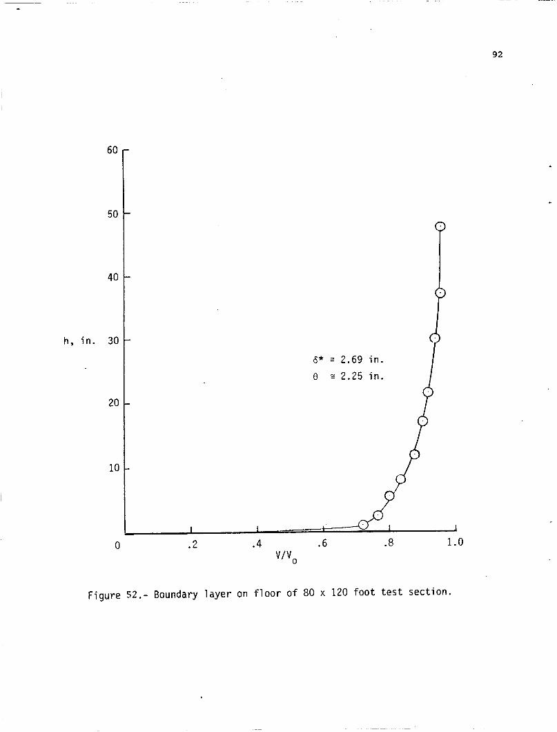
The 3 foot thickness of the ground board assembly suggested is based on removing most of the floor boundary layer that develops ahead of the ground board. The boundary layer on which the 3 foot thickness is based (fig. 52) was taken at the center of the floor turntable and indicates that most of the bound- ary velocity deficiency occurs below a height of about 36 inches (however the curve appears to asymptote a velocity ratio of about 0.95 rather than 1.0). A similar profile taken at the proposed leading edge of the ground board would show a slightly thinner boundary layer and permit reducing the depth of the structure. This would reduce the power required in the boundary layer removal blowers but would aggravate the structural problems.
The design of the blowers that supply the air to the BLC slots must await the completion of the above analytical studies which will determine the pressure ratio and mass flow required. The 2-600 HP blowers noted on figure 43 are based on very preliminary estimates and intended to give only a general idea of the requirements.
Other items such as the design of the slots themselves, their spacing, the slot adjusting system, honeycomb installation to insure uniform flow direction into the slots and the general air distribution system may need to be modified in light of the results of the analytical studies.
Experimental Verification. The multislot blowing BLC ground board design arrived at from the analytical studies will have to be verified experimentally. These tests can be made in the Ames 7- by 10-foot tunnel. the 7- by 10-foot tunnel will be used to survey and establish the flow field around, under and ahead of the models; first with a moving belt ground
The LDV system available in
24 installation and then with the blowing BLC board. The type of experimental setup envisioned is illustrated in figures 53 and 54.
A moving belt ground board will be built for the 7- by 10-foot tunnel and installed as close to the floor as the LDV system survey field will allow (fig. 53). The installation will include a system to remove the boundary layer ahead of the belt as is customary in such installations.
Tests over the belt ground board will be followed by similar tests over a multislot BLC board as shown in figure 54. This installation will use the same suction boundary layer removal system as used with the belt to insure that the BLC board starts with minimum boundary layer.
The verification and development tests should include both jet and jet flap configurations. The two models recommended are shown in figures 5 5 and 5 6 . The jet flap model (fig. 5 5 ) recommended is the model used in the previous blowing slot ground board investigation (ref. 4 3 ) and will provide for direct compari- sons with that investigation. The 2-inch diameter jet model shown in figure 56 will be constructed specifically for these investigations and will also be used to obtain some of the much needed fundamental data on the effects of pressure ratio and ground board boundary layer on the ground vortex as was indicated in the section on Research Needs above.
Both models will be supported from behind the ground board on a strut system that will provide for changing the height of the model in 2-inch incre- ments as indicated in figures 53 and 5 4 .
The multi-slot blowing BLC ground board will be arranged so that the effects of the spanwise extent of boundary layer control can be investigated in figure 54. pressure taps on 1/2-inch intervals to be used to correlate the ground vortex position determined by the LDV surveys with the position determined from pressure distributions in earlier investigations (refs. 9 and 24).
In addition the centerline of the ground board will be fitted with
The Test Program. The verification test program is presented in Table I. The test program for the 2-inch jet model has a two-fold purpose. First to verify ~-
and develop the blowing BLC ground board concept, and second to provide funda- mental data on the effects of jet pressure ratio, ground boundary layer and ground simulation technique on the location and strength of the ground vortex and related flow field.
The test matrix that can be convered by the 2-inch jet model is shown in figure 5 7 . The actual free stream velocities required to achieve a desired effective velocity ratio because of differences in the temperature and, therefore, the density of the jet and free stream air at the time the tests are run.
Ve may be slightly different than those of figure 57
Experience has shown that belt speeds of more than about 100 feet per second are difficult to achieve. Therefore, the fundamental investigation of the effects of pressure ratio and ground board boundary layer on the ground vortex flow field that can be run over the belt will probably be limited to those combinations of pressure ratio and effective velocity ratio shown by the small circles on figure 57. This fundamental investigation will be extended to
25 o t h e r combinations ( t h o s e shown by the x's) a f t e r t h e blowing BLC system has been chosen.
The test program (Table I) can be discussed i n s e v e r a l phases. The f i r s t group of tests (A, B , and C i n Table I) w i l l be s t a t i c tests made i n a l a r g e room (no t i n t h e test s e c t i o n so as t o avoid flow r e c i r c u l a t i o n problems). A f t e r t he b a s i c c a l i b r a t i o n s of t he nozzle (Group A ) , surveys of t he w a l l j e t generated by t h e 2-inch nozzle (Group B) w i l l be made over t he b e l t t o determine t h e e f f e c t of b e l t speed on t h e wall j e t development wi th d i s t a n c e forward of t h e impingement po in t . These tests w i l l cover a range of j e t p r e s s u r e r a t i o s and he igh t s .
The next group of tests w i l l be made over t h e blowing BLC ground board and w i l l cover t h e same range of p re s su re r a t i o s and he igh t s . BLC blowing rates b racke t ing t h e rate p red ic t ed by the a n a l y t i c a l p r e d i c t i o n s of t h a t r equ i r ed t o match t h e b e l t e f f e c t w i l l be i n v e s t i g a t e d . The r e s u l t s of t h e Group B and C tests w i l l be compared with t h e a n a l y t i c a l p r e d i c t i o n s of t he blowing rates needed t o c o n t r o l t h e f r e e stream boundary l a y e r t o determine the range of blowing rates t h a t w i l l be i n v e s t i g a t e d i n wind on tests i n t h e 7- by 10-foot tunnel .
The f i r s t series of tests i n the 7- by 10-foot t unne l w i l l be over t h e b e l t and a t belt speeds equal t o t h e f r e e stream v e l o c i t y (Group D i n Table I). This series of tests w i l l provide t h e fundamental d a t a needed on t h e e f f e c t s of j e t p re s su re r a t i o on t h e p o s i t i o n and s t r e n g t h of t h e ground v o r t e x f o r t h e case of zero boundary l a y e r . The test series w i l l cover t he complete range of j e t pres- s u r e r a t i o s and e f f e c t i v e v e l o c i t y r a t i o s p o s s i b l e with t h e b e l t ( f i g . 5 7 ) f o r j e t d e f l e c t i o n s of 60, 90, and 120 degrees through a range of he igh t s .
The second series over t h e b e l t (Group E) w i l l i n v e s t i g a t e t h e s e n s i t i v i t y of t he ground vor t ex flow f i e l d t o ground boundary l a y e r f o r a more l i m i t e d range of o p e r a t i n g cond i t ions . The combination of t he r e s u l t s of t h e series D and E tests should answer most of t he open ques t ions with regard t o the ground vor t ex i n STOL o p e r a t i o n s d i scussed i n t h e Research Needs Sect ion.
The flow f i e l d s defined by the LDV surveys i n the Group D tests w i l l a l s o provide t h e b a s e l i n e d a t a f o r e v a l u a t i n g t h e e f f e c t i v e n e s s of t h e blowing BLC ground board which w i l l be i n v e s t i g a t e d i n the Group G and H test series. . P r i o r t o t h e s e tests a few runs w i l l be r equ i r ed wi th t h e model out t o measure t h e build-up of t h e f r e e stream boundary l a y e r on the ground board and t o determine t h e blowing r equ i r ed t o e l i m i n a t e it. These r e s u l t s , along wi th the blowing r equ i r ed t o s i m u l a t e t h e b e l t under s t a t i c cond i t ions (Group C tests) , w i l l h e l p t o determine t h e range of blowing t o be used i n t h e Group G and H tests t o e v a l u a t e t h e e f f e c t i v e n e s s of t h e blowing BLC ground board. The abbrev ia t ed range of o p e r a t i n g cond i t ions is i d e n t i f i e d i n f i g u r e 57 f o r b e l t e v a l u a t i o n purposes. diameter, and a t one ope ra t ing cond i t ion , but w i l l cover a range of blowing rates and w i l l i nc lude spans of blowing on the ground board of 2, 4 , and 6 f e e t . A recommended blowing rate and span w i l l be chosen on the b a s i s of t h e s e tests. The adequacy of t he chosen blowing BLC system w i l l be eva lua ted f o r a wider range of o p e r a t i n g cond i t ions i n t h e Group H tes t series and a d d i t i o n a l tests as needed w i l l be run i n the Group I series.
The i n i t i a l series of tests w i l l be made a t a he igh t of one jet
26 The final part of the program will be to install a mockup of the dynamic
model support system planned for the 80- by 120-foot test section to evaluate the flow field around it and determine any interference at the model station.
A similar test program will be conducted with the jet flap model (fig. 55). The test range will be similar to that used in reference 43 and, as in reference 4 3 , the principal data will be wing pressure distributions and flow field surveys (Table I).
Flow Distribution Rig Tests. The ground board concept proposed (fig. 43) assumes that the air flow for the blowing BLC slots will be provided by two specially developed blowers installed at either side of the ground board near the leading edge. The flow from these blowers will be ducted down each side of the board so that it can find its way into the passages feeding each individual blowing slot. Care will have to be taken to insure uniform and equal flow from all the slots.
Preliminary analysis indicates that the mass flow required will be small and the velocities in the passages will be very low (probably less than about 50 feet per second) which should ease the problem. Nevertheless, a mockup of one front corner of the ground board will probably be required to investigate the flow distribution problem and develop any turning vanes and/or flow metering devices to insure equal and uniform flow from all the slots.
Development Schedule. The development, construction, and installation of the blowing BLC ground board will require considerable time. An approximate sched- ule, as now envisioned, is presented in figure 58
bving Belt Ground Boards
It is recommended that the initial steps toward development of a blowing BLC ground board for the 80- by 120-foot tunnel be undertaken. However, it is recognized that there are difficult and conflicting requirements to be met. If at some point in the development of the blowing BLC ground board it appears such a ground board is impractical, a second look at the use of a moving belt ground board may be necessary.
The problems of building and operating a moving belt ground board increase with size. A t present there is only one large operational belt .in the United States. This belt is used in the Boeing Vertol wind tunnel near Philadelphia.
The Vertol belt is 18 feet wide, 26.5 feet long (between roller centers) and has an operational speed range of 8 to 170 feet per second. The personnel that operate it indicated that belts need to be replaced frequently. Typical comments were, "It takes a lot of tender care and feeding..." to keep it running and "it ate two and one half belts on the last job."
The Lockheed Georgia tunnel used a dual belt installation, one on each side of a centerline model support strut. However, they have been scrapped. Lockheed uses blowing for the automobile tests they frequently run.
The belt for the Langley 4- by 7-meter tunnel is inactive, but could be made operational. It is 14 feet wide and 20 feet long and was supposed to operate at speeds up to 330 feet per second; however, the material of the first
27 belt failed at a speed of only 150 feet per second and the speed has subse- quently been limited to 120 feet per second.
As far as is known no one has operated a hot jet over a belt. Such opera- tion may be possible if the hot jet is only allowed to impinge on the belt while it is running and then only for a very brief period of time.
If consideration must be given to the use of the large belt in the 80- by 120-foot test section, the type of installation shown in figure 58 (three copies of the Vertol belt side-by-side) should be considered. The boundary layer removal system proposed for the blowing BLC ground board will still be needed as will the return flow at the downstream end of the board assembly. In addition an auxiliary boundary layer removal system will probably be needed just ahead of the belt unless the belt is made long enough to reach forward to the main bound- ary layer removal system.
If a moving belt ground board is to be considered, it is recommended that a workshop of personnel who have experience with the design and operation of moving belt ground boards be convened to discuss and present their experience and recommendations.
INITIBL RESEARCH INVESTIGATIONS
Five research investigations that should be undertaken early in the use of the ground effect equipment discussed above can be identified. These include tests of models of the QSRA and YAV-8B aircraft which provide unique opportuni- ties for small-/full-scale comparisons and full scale surveys and measurements of the wall jet development (and associated suckdown), and surveys of the ground vortex flow field and hot gas ingestion using the J-97 powered rig.
Complete W e 1 Programs
The well documented flight test data on the ground effects experienced by the QSRA Upper Surface Blowing configuration presented at the workshop by Stevens provide a unique opportunity for wind tunnel flight test correlation. Many model/flight data correlation problems can be traced to differences between the model configuration and configuration of the airplane that was eventually flown. Construction and test of a model of the QSRA configuration that accu- rately duplicates the geometry of the aircraft should eliminate these problems for this configuration and provide the data for a high quality wind tunnel/ flight correlation study. The flight test data should be reviewed to develop a test program and run schedule that will obtain the necessary wind tunnel data.
Similarly, the YAV-8B aircraft is in flight test status at Ames and provides a similar opportunity for wind tunnel/flight comparison on a jet V/S"OL configuration. The flight test personnel and the wind tunnel personnel should get together and develop coordinated flight test and wind tunnel test programs to provide the data needed. Test programs for both the 80- by 120-foot test section and the outdoor static test stand should be developed.
28 Fundamental Investigations
In a d d i t i o n t o tests of s p e c i f i c models, t h e i n v e s t i g a t i o n of some of t h e fundamental flow f i e l d s a s s o c i a t e d with ope ra t ion i n ground proximity should be undertaken using t h e J-97 r i g . The f i r s t of t h e s e (Table 11) should be an i n v e s t i g a t i o n on t h e outdoor s t a t i c test s t and of t h e e f f e c t s of j e t tu rbu lence on t h e w a l l j e t generated by a s i n g l e j e t nozz le , a t f i x e d h e i g h t , and on t h e a s s o c i a t e d suckdown on a c i r c u l a r blocking p l a t e ( f i g . 6 0 ) .
These i n v e s t i g a t i o n s should be followed by an i n v e s t i g a t i o n i n t h e 80- by 120-foot tes t s e c t i o n of t he development of t h e ground vor t ex generated by a s i n g l e jet (Table 111). These tests should inc lude measurements t o d e f i n e t h e d i s t r i b u t i o n of both v e l o c i t y and temperature i n t h e flow f i e l d , t h e i r rate of change, and t h e rate of change of t he e n t i r e flow f i e l d with rate of climb and descent . This i n v e s t i g a t i o n should be followed by and c o r r e l a t e d wi th a t h i r d i n v e s t i g a t i o n (Table IV)--an i n v e s t i g a t i o n of t h e hot gas i n g e s t i o n f o r va r ious i n l e t l o c a t i o n s .
The b a s i c appa ra tus f o r t h e s e i n v e s t i g a t i o n s is presented i n f i g u r e 3 7 . Two J-97 engines w i l l be mounted i n t h e second c a r r i a g e of t h e dynamic support system. Only t h e lower engine w i l l be needed f o r t h e f i r s t and second i n v e s t i - g a t i o n s t o provide t h e hot gas t o t h e nozzle. The top engine w i l l be added f o r the last i n v e s t i g a t i o n t o p o w e r the i n l e t . An a u x i l i a r y nozzle and t w o bu t te r - f l y valves w i l l be needed i n t h e supply l i n e t o t h e r e sea rch nozzle so t h a t t h e engine can be s t a r t e d and brought up t o t h e d e s i r e d o p e r a t i n g c o n d i t i o n be fo re t h e flow is d i r e c t e d a t the ground board. A t t i m e zero t h e b u t t e r f l y va lves w i l l be a c t u a t e d t o r e d i r e c t t h e flow from the a u x i l i a r y nozzle t o the r e s e a r c h nozzle and t h e take-off o r landing maneuver t h a t is t o be s t u d i e d w i l l be s t a r t e d .
The development of t h e flow f i e l d w i l l be documented by f o u r sets of meas- urements. High speed photographs ( f i g . 61) of the developing hot gas cloud (de f ined by smoke o r steam i n j e c t e d i n t o the nozzle) w i l l be taken from s e v e r a l angles . Simultaneously, p re s su res on t h e ground board along t h e c e n t e r l i n e of t h e tunne l w i l l be recorded by high speed p r e s s u r e t r ansduce r s .
The v e l o c i t y d i s t r i b u t i o n w i t h i n t h e flow f i e l d can be measured us ing t h e l a r g e scale Laser Velocimeter System developed f o r t h e 40- by 80- and 80- by 120-foot test s e c t i o n s ( r e f . 47). A s e p a r a t e rake of high response thermo- couples w i l l be r equ i r ed t o measure t h e temperature d i s t r i b u t i o n . These rakes w i l l probably have t o be b i d i r e c t i o n a l as dep ic t ed i n f i g u r e 62 because a s i g n i - f i c a n t p a r t of t he flow i n t h e w a l l j e t is flowing forward, i n t h e oppos i t e d i r e c t i o n t o t h e f r e e stream flow.
In o rde r t o survey t h e e n t i r e flow f i e l d , s e v e r a l d u p l i c a t e runs w i l l be r equ i r ed f o r each s imulated ope ra t ion ( f o r each descent rate, f o r example). In o rde r t o minimize t h e number of runs, t h e cons t an t he igh t runs shot Id be completed f i r s t and analyzed t o t r y t o p r e d i c t t he most important s t a t i o n s a t which t h e measurements should be made du r ing the climb and l and ing descent s imulat ions.
Tests should be made f o r both v e r t i c a l j e t s (V/STOL a i r c r a f t o p e r a t i o n s ) and with the j e t d i r e c t e d 30 degreeg o r more forward of t h e v e r t i c a l t o s i m u l a t e t h r u s t r e v e r s e r operat ion.
8
29 The hot gas ingestion investigation should be made for the four inlet loca-
tions shown in figure 63. The operations simulated and the operating conditions used in the jet flow field investigation discussed above should be duplicated so that the actual ingestion experienced can be correlated with the temperature distribution obtained from the flow field investigation. In addition some runs should be made at reduced inlet flow to determine the sensitivity of the inges- tion to the inlet flow rate. This information will be useful in evaluating the need for full inlet flow simulation in propulsion system simulation.
SUMMARY OF RECOHHENDBTIONS
This study and the workshop that accompanied it has led to the following recommendations:
Equipment for the 80- by 120-Foot Test Section and the associated Outdoor Static Test Stand
1) A program to develop a multiple-slot blowing BLC ground board (as an alternative to a moving belt ground board) for the 80- by 120-foot test section should be undertaken.
2) The model support system should include the capability to produce rapid vertical motion so that the effects of rate of climb and descent can be studied.
3) Models of specific configurations should be powered with ejector based engine simulators with burners added to provide hot exhaust flows. For fundamental research investigations such as flow field studies, remotely mounted engines such as the J-97 should be used.
Blowing BLC Ground Board Development
4 ) The development of the multi-slot blowing BLC ground board should start with analytical studies of the interaction of the BLC flow with the wall jet flow from the model to determine the blowing requirements.
5) An experimental program will be required to develop and verify the . design of the ground board. This program will include survey of the flow fields generated by a 2-inch nozzle and a small jet flap model tested over a small moving belt ground board to provide a base for comparison with surveys over a multiple slot ground board for verifica- tion of the design.
Research Investigations
6 ) Five research investigations should be planned as the initial ground effect studies in the 80- by 120-foot tunnel and the outdoor static test stand. They are:
a) Tests of a model of the QSRA U S B jet flap airplane for correlation with flight test results.
30 b) Tests of a model of the YAV-8B V/STOL airplane for correlation
with flight test results.
c) Measurements of the effects of jet turbulence on the wall jet and associated suckdown using the J- 97 powered rig.
d) Surveys of the development of the ground vortex flow field from a J-97 engine during simulated take-off and landing.
e) Related surveys of the hot gas ingestiuon for selected inlet locations.
7) Increased emphasis should be placed on the development of analytical codes to predict the effect of the ground on the flow fields around the configuration and the resulting effects on the aerodynamic characteristics.
8) Other areas of ground effect research that should be studied include:
a) Single jet suckdown in hover.- The effects of jet turbulence on the development of the wall jet and, in turn, on the suckdown will be studied in the program recommended above. These tests need to be extended to investigate other jet characteristics such as exit distribution and temperature. Also the effects of the size of the room in which tests are made should be investigated.
b) Multiple jet fountain effects and additional suckdown.- The flow field between the jets and the fountain and its effect on the induced pressure distribution and net suckdown need to be studied. Also the effects of body contour and flow control devices need more systematic study.
c) Ground vortex flow field and effects.- The effects of jet pressure ratio and of the boundary layer on the ground board will be investigated in the development program for the multi-slot blowing BLC ground board and in the large scale (J-97 powered) tests in the 80- by 120-foot test section. These tests should be extended to include studies of the effects of jet characteristics such as turbulence, exit flow distribution, etc.
d) Downwash at the tail.- The ground effect studies of the QSRA and YAV-8B configurations.should include investigations of the effects of ground proximity on the downwash.
e) Hot gas ingestion.- Future programs in the 80- by 120-foot test section using the J-97 powered rig should include dual nozzles and the effects of body and other surfaces and shapes betweer the nozzles and inlets on the hot gas ingestion.
8
31 REFEReNCES
1. "Proceedings of Workshop on V/STOL and STOL Ground Effects" Proposed NASA CP , August 1 985.
2. Henderson, C., Clark, J., and Walters, M., "V/STOL Aerodynamics and Stability and Control Manual", NADC-80017-60, January 1980.
3. Wyatt, L. A., "Static Tests of Ground Effect on Planforms Fitted With a Centrally-Located Round Lifting Jet", Ministry of Aviation, CP74 9, June 1 962.
4. Hall, G. R., "Scaling of VTOL Aerodynamic Suck-down Forces", AIAA Journal of Aircraft, July-August 1967, pp. 393-394.
5. Spreeman, K. P. and Sherman, I. R., "Effects of Ground Proximity on the Thrust of a Simple Downward-Directed Jet Beneath a Flat Surf ace", NACA TN 4407, September 1958.
6. Gentry, G. L. and Margason, R. J., "Jet-Inducted Lift Losses on VTOL Configurations Hovering In and Out-of-Ground Effect", NASA TN D-3166, February 1 %6.
7. Vogler, R. D., "Interference Effects of Single and Multiple Round and Slotted Jets on a VTOL Model in Transition", NASA TN D-2380, August 1964.
8. Christiansen, R. S., "A Large Scale Investigation of VSTOL Ground Effects", AIAA-84-0366, January 1984.
9. Stewart, V. T. and Kuhn, R. E., "A Method for Estimating the Propulsion Inducted Aerodynamic Characteristics of STOL Aircraft in Ground Effect", NADC-80226-60, August 1983.
10. Lummus, J. R., "Flow-Field Characteristics and the Effect of Jet-Exhaust Simulation for V/STOL Vehicles Near the Ground", Proceedings of the NADC V/STOL Vehicles Near the Ground", Proceedings of the NADC V/STOL Aircraft Aerodynamics Symposium, Naval Postgraduate School, Monterey, Calif., May 1979.
11. Hall, G. R. and Rogers, K. H., "Recirculation Effects Produced by a Pair of Heated Jets Impinging on a Ground Plane", NASA CR-1307, May 1969.
12. Yen, K. T., "On the Vertical Momentum of the Fountain Produced by Multi-Jet Vertical Impingement on a Flat Ground Plane", NADC-79273-60, November 197 9.
13. Kuhn, R. E., "An Engineering Method for Estimating the Induced Lift on V/STOL Aircraft Hovering in and out of Ground Effect" , NADC-80246-60, January 1 981.
14. Foley, W. H. and Sansone, J. A., "V/STOL Propulsion-Induced Aerodynamic Hover Calculation Method", NADC-78242-60, February 1980.
32 15. Foley, W. H. and Finley, D. B., "Fountain Jet Turbulence", AIAA-81-1293,
June 1 981.
16. Spong, E. D. et al., "V/STOL Jet-Induced Interactions", Proceedings of NADC Workshop on V/STOL Aerodynamics, Naval Post Graduate School, Monterey, Calif., May 1979.
17. Wohllebe, F. A. and Migdal, D., "Some Basic Test Results of V/STOL Jet- Induced Lift Effects in Hover", AIAA-7 +033 9, January 1 97 9.
18. Johnson, D. B. et al., "Powered Wind Tunnel Testing of the AV-8B: A Straightforward Approach Pays Off " , AIAA-7 9-0333, January 1 97 9.
19. Williams, J., Butler, S. F. J., and Wood, M. N., "The Aerodynamics of Jet Flaps", RAE R&M No. 3304, January 1961.
20. Joshi, P. B., "Generic Thrust Reverser Technology for Near Term Applica- tion", AFWL-TR-84-3094 Vol. I-IV, February 1985.
21. Schwantes, E., "The Recirculation Flow Field of a VTOL Lifting Engine", NASA TT F-14912, June 1973.
22. Abbott, W. A . , "Studies of Flow Fields Created by Vertical and Inclined Jet When Stationary or Moving Over a Horizontal Surface", RAE CP No. 911, 1967.
23. Weber, H. A. and Gay, A., "VTOL Reingestion Model Testing of Fountain Control and Wind Effects", Prediction Methods for V/STOL Propulsion Aerodynamics, Vol. 1, Naval Air Systems Command, pp. 358-380, 1975.
24. Colin, P. E. and Olivari, D., "The Impingement of a Circular Jet Normal to a Flat Surface with and without Cross Flow", AD688953 European Research Office, United States Army, January 1969.
25. Turner, R. T., "Ground Influence on a Model Airfoil with a Jet-Augmented Flap as Determined by Two Techniques", NASA TN D-658, February 1961.
26. Werle', Henri, "Simulation de L'Effet de Sol au Tunnel Hydronamique (Ground Effect Simulation at the Water-Tunnel)", La Rech. Aerospatiale, No. 95, July-August 1963, pp. 7-15.
27. Hackett, J. E. et al., "Ground Simulation and Tunnel Blockage for a Jet- Flapped Basic STOL Model Tested at Very High Lift Coefficients", NASA CR-137857, March 1976.
28. Campbell, J. P., Hassell, J. L., Jr., and Thomas, J. L., "Recent Research on Powered-Lif t FTOL Ground Effects" , AIAA-77-574, June 1977.
2 9. McCormick, B. W. , "Aerodynamics of V/STOL Flight ," Academic Press, 1967.
30. Vogler, R. D., "Wind Tunnel Investigation of a Four Engine Externally Blow- ing Jet-Flap STOL Airplane Model", NASA TN D-7034, December 1970.
33
of the Kestrel (xv-6A) Vectored-Thrust V/STOL Airplane", NASA TN D-6826, 31. Margason, R. J. et al., "Wind-Tunnel Investigation at Low Speed of a Model
July 1972
32. Hall, G. R., "Model Tests of Concepts to Reduce Hot Gas Ingestion in VTOL Lift Engines", NASA CR-1863, July 1971.
33. Clark, R. S. and Vasta, S. K., "Development of the AV-8B Propulsion Sys- tem", AIAA-84-2426, October 1 984.
34. McLemore, H. C. and Smith, C. C., Jr., "Hot-Gas Ingestion Investigation of Large-Scale Jet VTOL Fighter Models", NASA TN D-460 9, 1 % 9.
35. Bore, C. L., "Ground Based Testing Without Wind Tunnels", AGARD Report No. 710, Special Course on V/STOL Aerodynamics, June 1984.
36. Abbott, W. A., "Estimation of Intake Temperature During V/STOL Operation from Model Tests." NGTE Note NT.600, March 1966.
37. Milford, C. M., "Scaling Factors for Hot Gas Recirculation", BAe-KAD-N-GEN- 2787, August 1981.
38. Milford, C. M., "Further Consideration of Recirculation Temperature Seal- ing Laws", BAe-KAD-N-GEN-2844, June 1 982.
39. Amin, N. F. and Richards, C. J., "Thrust Reverser Exhaust Plume Reinges- tion Model Tests", Journal of Aircraft, Vol. 21, June 1984, pp. 401-407.
40. Kotansky, D. R., "Jet Flow Fields", Special Course on V/STOL Aerodynamics, AGARD Rpt. No. 710, June 1984, pp. 7-1 to 7-48.
41. Stevens, V. C. and Wingrove, R. C., "STOL Ground Effect Determined from Flight Data", AIAA-77-576, June 1977.
42. McLemore, H. C., "Considerations of Hot-Gas Ingestion for Jet V/STOL Air- craft", NASA SP-116, April 1966, pp. 191-204.
43. Hackett, J. E., Boles, R. A . , and Praytor, E. B., "Ground Effect for V/STOL Aircraft Configurations ,and its Simulation in the Wind Tunnel: Part I1 Experimental Studies", NASA CR-114,496, no date.
44. McGee, R. J., Beasley, W. D., and Foster, J. M., "Recent Modifications and Calibration of the Langley Low-Turbulence Pressure Tunnel", NASA TP 2328, July 1984.
45. Hoerner, S. F., "Fluid-Dynamic Drag", Published by the author, 1958.
46. Hackett, J. E., Praytor, E. B., and Caldwell, E. O., "Ground Effect for V/STOL Aircraft Configurations and its Simulation in the Wind Tunnel, Part 111, The Tangential Blowing Ground Board as an Alternative to a Moving Ground: Tunnel", NASA CR-114,497, no date.
Application to the NASA/Ames 40- by 80-foot Wind
34 47. Reinath, M. S., Orloff, K. L., and Snyder, P. K., "A Laser Velocimeter
System f o r Large-Scale Aerodynamic Testing", NASA TM 84393 , January 1984.
35 TABLE 1.- DEVELOPMENT OF BLOWING BLC GROUND BOARD
7- by 10-Foot Tunnel Test Program (2-Inch Jet Model)
Compare B and C t o determine BLC system requi red t o match b e l t f o r s ta t ic cond i t ions ; compare with a n a l y t i c a l estimates and wi th BLC r equ i r ed t o e l i m i n a t e f r e e stream boundary laser.
Tests i n 7- x 10-foot Tunnel - Over Belt:
D - LDV Surveys of Wall Jet and Ground Vortex Flow F i e l d s (Base l ine and Fundamental S tud ie s )
vb/v, = 1.0 V e = 0.03 t o 0.2 Pn/Po = 1.05, 1.2, 1.4, 2 h/d = 1, 2, 4 , 8, 12, 20 6 = 60, 90, 120
E - S e n s i t i v i t y of Flow F ie ld t o Boundary Layer
Boundary Layer P r o f i l e - Jet Off Survey Flow F ie ld - Jet On
- 6 - 9 0 - Ve = 0.03 - PnPo = 1-05, 1.2, 2
t o 0.2
- h/d = 1, 4 , 12
11 surveys x 6 x 3
= 198 surveys
5 surveys
x 3
x 3 = 45 surveys
36 Table I. - Continued .
(2-Inch Jet Model, Concluded)
Tests Over the BLC Ground Board:
F - Determine BLC Required t o Replace Momentum Loss i n Boundary Layer (Clean Tunnel), Compare wi th Ana ly t i ca l Estimates and wi th B and C Comparison Above.
G - Determine BLC Configurat ion Required t o Match B e l t
I n i t i a l Tests @ h/d - 1.0, V e = 0.1, 6 = 90,
Cu range S l o t Span = 2, 4 , 6 f t .
and Pn/Po = 1.2
H - Check Tests with Chosen BLC Configurat ion and Criteria For S e t t i n g Blowing Rate
Ve 0.03 t o 0.2
h/d = 1, 4 , 12 6 = 60, 90, 120
p,/P, = 1-05, 1.2, 2
I - Addi t iona l Tests as Required
J - I n s t a l l Mock-up of Dynamic Rig and Check f o r I n t e r f e r e n c e
V e 0.03 t o 0.2 Pn/Po = 1.05, 1.2, 3 h/d = 1, 4 , 12
5 surveys n
x 3 = 15 surveys
5 surveys
x 3 x 3
= 45 surveys
5 surveys
x 3 = 15 su rveys
37 Table I.- Concluded.
(Jet-Flap Model)
Tests i n 7- x 10-foot Tunnel - Over B e l t :
K - LDV Surveys of Ground Vortex and Flow Under Model and Pressure D i s t r i b u t i o n s on Wing
L - Determine Floor BLC Required t o Match B e l t
Cu = 1.0, 3.0 wing * h = 3 , 5
S l o t Span = 2 , 4 , 6 f t Cu = Range f l o o r
M - Check Tests with Chosen BLC Configurat ion and Criteria f o r S e t t i n g Blowing Rate
Cu = 0.3, 0.7, 1.0, 2.0, 3.0 wing h = 3 , 4 , 5 , 10, 20
5 surveys x 5 x 2
= 50 surveys
2 surveys x 2 x 3 x 5
= 60 surveys
5 surveys x 5
= 25 surveys
38 TABU 11.- EFFECTS OF TURBULENCE ON WALL JETS AND !XJcRDowN
Tests on the Outdoor Static Test Stand
Configuration
Single vertical nozzle Three circular planforms, D/d = 3 , 6 , 9 Nozzle inserts to produce three levels of turbulence
Types of Measurements
Suckdown force on planforms Pressure distributions
- Four radial rows of orifices on planform - Four radial rows of orifices on ground board - High response static pressures at impingement point and selected radial stations on ground board
Wall jet surveys, at five radial stations
- Vertical rake of t o t a l and s t a t i c probes - Turbulence surveys through wall jet
Temperature distributions, at same stations as wall jet surveys
Operating Conditions, at constant height
Pn/p = 1.2, 2, and maximum for J-97 h/d = 1, 2, 3 , 5, 9 Turbulence: minimum, intermediate, maximum
3 9 Table 111,- DEFINITION OF GROUND VORTEX FLOW FIELD AND J3OT G4S CLOUD
Test Program In 80- x 120-foot Tunnel
Configuration
Single nozzle, no inlet
Types of Measurements
Flow visualization, high speed photos as cloud (smoke or steam) develops Pressure distribution on ground board center line, fast response pressure
Flow velocity and angle, two rakes (one forward facing for free stream and gages
one aft facing for wall jet) of fast response pitot and angle heads supported from overhead; five survey stations Temperature distributions, fast response thermocouples on above rakes.
Fixed heights, determine rate of build-up of flow field. Close auxiliary nozzle at time zero and measure time history of flow field development until steady state is reached. Compare steady state with small scale steady state data Climb, climb accelerations = 0.02, 0.05, 0.1, 0.2 g's. Close trap door and start climb acceleration at rime zero and measure time history of flow field development. Descent, sink speed = 3 , 6 , 12, 20 fps. Measure time history of flow field development
40 TABLE Do- BM: GAS INGESTION !XUDXES
Test Program in 80- x 120-foot Tunnel
Configuration
Four inlet locations, single nozzle
Instrumentation
Fast response thermocouples across inlet face
Operation Conditions
Same as for flow field definition studies, additional runs at partial inlet flow to determine sensitivity at 0, 10, 20, 4 0 , 60, and 100% flow.
Operations Simulated
Same as for flow field definition studies
L W
J a
g --- I
a ;i' K L z W
I- O w U U W
3 0
3 0 z 2
42
.
I- t-
> a 3
I i
43
.
RADIAL WALL JET
F i g u r e 4 . - Founta in f l o w generated between a p a i r o f j e t s .
rc
44
0 V
c, aJ '3
L 0 cc
45
c W
-D
5 0
<
*I-
LL
46
Figure 8.- Formation o f ground vortex.
47
SECTION OF
Figure 9.- Flow f i e ld under j e t flap model with j e t impingement on ground. (Ref. 19) a = 15", Cp = 2.1, H/? = 1.5, 6 'L 50"
Figure 2 6 . - Size of ground vortex recirculating f l o w
region generated by a single j e t .
65
.
Figure 27. - Remotely powered Harrier-type model.
66
.
Two e j e c t o r s each s i d e ( t o p and Bottom)
Space f o r burner
F i g u r e 2 8 . - "Hot E j e c t o r " powered H a r r i e r - t y p e model.
67
r Q + V m
II
c
0 cv d u3
I I I
u
F
rc 0
9) c > 0 I: I
N
W L 3 9)
L L
.C
0:
*I-
68
In 0 0
-n ln c -i 10 w c,
I
-I.
A
0 m 3 rD I rt
n W ID -h
P N U
- 11
0
v) m 0
0
-. I1
0
v) m 0
iu
69
70
0 4
0 m
0 N
0 -
3
O K
- K .I-
7
al -0 0 E -
? O n 4
- 0 d aJ L . 3 0 m z rc1 a J L E a J n arc1 m a L .I- u
c .I-
ln 0 3 _ . .C L)
I
N M
71
Figure 33.- Rolls-Royce dynamic rig for studing the effect of landing sink rate on hot gas ingestion,
72
L tu 0
- 0 * E: 3 0 L a
m
Y V tu L I-
\ 4
m t .I- - .F
W
i
c, V aJ L ri- aJ -0 t 3 0 L 0-l
v W re + W
L % .. L a, > W L
V tu re
u 0 E m t
> 0 r: I
.F
I
73
t-20
I "Hot Ejector"
B = -+30° Ground Board see Fig . 41
Boundary Layer Remova 1 see Fig. 41
f Balance
Dynamic R i s
Section A-A
h
Figure 35.- General arrangement of dynamic rig and ground board i n s t a l l a t i o n .
74
. . - - __ _.
L I
- - - -
Precision Tracks
Angle o f Attack
Hydraulic Actuator cx = -10" t o +30" Ground Board
'New Support Knees Balance Frame
F1 oor Turntabl e
Figure 3 6 . - I n s t a l l a t i o n o f dynamic r ig on model support system.
75
a
T A
- J-87
Engine Mounting Po in ts Engine Fount Yoke
,
Sect ion B-B
I n l e t Flow f o r Hot Gas Inges t i on
By-Pass Valves Data P o s i t i o n
,-Replaceable Sect ion f o r 1 ’ Angle Change
Turbulence Contro l Dual Nozzles
I I
Sect ion A-A
F igure 37.- 5-97 Engine i n s t a l l a t i o n and car r iaqe.
76
/ stopp ing d i s t a n c e --- ; I I 1
16 ‘:I 1 \ \ 1
\ \
\ I I I I
Height , f t
6
I I Data Range 14 c I ~ 1 6 f t
I
I I I
I I
I
I I I
I I
Scaled l a n d i n g gear ,- Extended
S i n g l e speed, f p s
a ) Typ i c a l h e i gh t/ s i n k- speed p r o f i 1 es . F i g u r e 38 . - T y p i c a l s imu la ted land ings .
1 4
2
a
77
10
a
6
g ' s
4
2
0 4 8 12
S i n k speed, f p s
Landing gear stroke
1 - foot ' I res ea rc h 'I
stopping distance
b) Stopping decelerations.
Figure 3 8 . - Concluded.
78
79
.
Height,
20 .-
16 -
12 -
ft
I L Stopping distance
7
L
Data range
I I I I I 0
301 A 20
C 1 imb speed,
fps 10
Climbing accelerat ions, g ' s
.1
l g stopping dece lera t ion
0 1 2 3 4 Time, sec.
Fiqurc! 40 . - Simulated take-offs.
80
Steady s t a t e
5 f t / s e c 1 Model s c a l e 15 f t / s e c s i n k r a t e
( 5 f t / s e c f u l l s c a l e )
0 A Temp.
F i q u r e 40.- E f f e c t o f r a t e of descent on t h e onset of h o t gas
i n g e s t i o n .
.
81
\
‘L E x i s t i n g model suppor t system p i t
F i g u r e 41. - I n s t a l l a t i o n o f dynamic r i g and 5-97 c a r r i a g e
on outdoor s t a t i c t e s t f a c i l i t y .
a2
_I---
c, P aJ V t 0 V
c3,
L .r
ln 0 n I
(u d
aJ
83
/ 4- -4
c, Q aJ V S 0 V
0 L (21 0 n -0 S 3 0 L CJ,
V
m 0, E: .r 3 0 - m
I
aJ L 3
84
. . . . .- - . . - . . . , . .
0 0 cu
0 2
0 a rl
0 d 4
0 cu rl
0 0 4
0 m
0 co
0 d
0 (v
0
0 0 0 rl
X
E cc U
aJ n
5 ? 0 z
L aJ 6 ? n ? la
U L aJ E E 0 W
la V
n c, rcI
L 0 ce Q rc) E aJ V S fo
0 ce L aJ
.r
7
.r
E
a I
d d
aJ L
85
12
10
a
h/d 6
4
2
0
No ground . e f f e c t
/ /
/ ,/ / ,, /
/ /
/ ,/
1 I I 1 1 1 I 5 10 15 20 25 30 35
v ./v J O
t t t t t
v / v . 7 ve .5 .2 .1 .05 .03
O J
F i g u r e 45.- H e i g h t / v e l o c i t y - r a t i o range i n which s i n q l e s l o t BLC i s adequate.
(Ref. 43)
86
\,
/ \
c -' \
0 o > I I I I 0 >
>"-" I b I I I
I
c c c c c o 0
c 0 0 J a
aJ L 3 13,
a, Y (0 L
87
.
a c, 0 v) \
*E
- n
0 r\ " h " c o l I 4 1 ' I * * I I
W 1 0 1
V aJ v) \ m e a v) 000 m 0 0 0 3 . . . 7 0 v)
0400
* p: *I- v)
!= 0
c 0
m c E O
'5 '$ o v l - w
I - @ m v ) .I- aJ W C , c w l - m a e l - m a u
n v )
>, c c a J o r -
m c , C v m a J - I cc l e c c w o
88
VI P Y-
Io d (v
II
> 0
1 d
/ 0 /
/ /
/
m 0 > \
>a
(v
m 0
3
> \
>
cu
J 4
Io d (v 0 0 0 0
v)
U aJ L .C
L
*I- c, v) aJ cc 0
E 0 v)
L CrJ
0 0
89
0 n 0 d
A
/ /
I I
/ /
/
d
/ / /
/ /
/ /
/
I I I I I 0 co W d (v
4 rn
m
d
CI)
N
4
m
d
CI)
N
P a x L 0
u c 5 * r *I-
aJ E - o w E * U
u r n
V- O L
0 T I C 0 m u .
90
I I
1
1
I
I
f
I
I
I I
I I I
1
0 II
> 0
c, aJ -7
? c ro 3 S 0
V J
U S la
c,
aJ
ce 0
c, W Q) + cc
W
I
c m aJ L 3 0,
LL
m
7
n
*I-
.
91
I
6-
4 -
2 - z /d
0 -
1.2-
.%-
z, i n .
.4-
I I
I I I
71--r4
I 24
I 8
il Pn/Pa = 2.0
h i d = 5.0
-I / 4 /--
/-- /
/ -
I 7
D is tance f rom j e t , x , i n .
Wal l j e t
\lo = 0
I 6
F i g u r e 51.- Est imated boundary l a y e r and w a l l j e t p r o f i l e s assuming
2 - i n c h s l o t spacing.
92
60
50
40
h , i n . 30
20
10
0
6* 2.69 i n .
e I 2.25 in .
.2 .4 .6 V / V o
.8 1 .o
F igu re 5 2 . - Boundary l a y e r on f l o o r o f 80 x 120 f o o t t e s t sec t i on .
93
1 . 1
Q, a
L C L
I -
I- ; E - 1
E c, v) h m
7
m > 0
L L aJ h 5
E
- 2 a m c 3 0
;
W u m 7 n -0 aJ u 5 L 0 re L W n
94
7
aJ E S 3 c,
c, 0 0 + 0, X
h
aJ r CI
S
m L m 0
m c 3 0 L m 0 d
el-
n
m I
u. v,
aJ L 3 cn LL *r
95
m d
c aJ -0 0 E
. .
0RIGINP-L PAGE Is OE POOR QUALITY
96
.125 i,H . 3" Typ
Turbulence Generating Plates
20 I I I
~ 5 0 0 .05" P i a . Holes on . l " Centers
- "0" Ring Seals ( 3 rqd.) Turbulence Reduction Screen
Figure 56.- Details o f 2-inch j e t model.
97
c
aJ aJ L LL-
0
rD
0
d
0 N
d rl
N
l-l
m 0 4
0
N
0 u3 0 0 l-l
- rc) 00
m a ml 0 7 m
rD
a3 N
L aJ > 0 tn c, v) aJU c , L
CO a 0 E rcIU LE:
tnn
m m - NI * ml
m m 0 0 0 O O 4 N r n . . . . .
0 0
e w
U L rb 0
0 E 3 0 L 0
V A
E ‘P c,
E UaJ aJE tnn 3 0
a J a J n > aJ o u c
n
m
F
Y 4 ira
0 Ln N
0 0 N
0 m 4
0 2
0 m
0
V c, aJ v) v) Q) \ I- c, rc I
*C
LL
aJ >
98
Ground board
CFD studies Experimental ve r i f i ca t ion (7 x 10)
Design and construction equipment Tests over b e l t Evaluation o f BLC
Design and cos t studies Air flow d i s t r ibu t ion tests Design and construct ion . I n s t a l l a t i o n i n 80 x 120
Dynamic model support system
Preliminary design studies Design and construct ion Ins t a l 1 a t ion
S t a t i c stand 80 x 120
Hot ejectors
Feasi b i l i t y s tud ies Development Production
Research program
Model preliminary design s tud ie s Design and construct ion models Test program
Outdoor s t a t i c t e s t stand Wall j e t and suckdown (597) Hot gas ingest ion (597)
80 x 120 foo t test sec t ion QSRA Ground vortex flow f i e ld (597) Hot gas ingestion (597)
YAV-8B
YAV-8B
0
1
do- l
I I I I I I
I I
I
I
1
I
I 1
3 I I I I I ‘ I
I I
b 0 0
I I
1 2 ’
0 I I I I I I I
I
U I I ! I I I I
1 I I I I
I
I I I I I . I I
b 0 0 R
I I 3 4
Years from Go-ahead
Figure 58. - Suggested development and t e s t schedule.
99
.
3 r Angle o f Attack Actuator --.,
c1 = 10" to 30"
Precision tracks
Hydraulic actuator 20' travel
I1
New support knees
Figure 59.- Alternative "belt" ground board installation
100
v) c aJ aJ L V v)
0 L r t 0 V
F
-0 E: tu c 0
r L aJ t aJ Is,
.r
tu
aJ u E aJ J L J I-
F
n
I, I
I
u : ’ I aJ
Y tu L I
I 2 > I L 3 v)
c, a, ’r)
c
aJ V S W c
3 n L J c,
rc 0
c, V aJ re rc aJ re 0
F tu U
L 0 ct
.
101
0 c, v) a J 0 > o I
c,
r\l
c , +
m 0
a
a
I I
I c, a
-1- c, E: aJ
0 E - aJ > aJ -0
U aJ
Y-
7
*r
3 0 c ' + 4- 0
+ 0 1
a 0
102
v) Y u m L
I-
F?+ 5 W L UaJ UIY
m W L W L LL
X W c, L 0 >
v) W Y a L
0,
Q 1 0 V 0
W -c c
c
E
L Q)
4
ET 0
a c, v) ET w
I
cv \D
C, ln 3 m
L
.- r X
3 0 ? W rc
C, c, 0 W I
U
I
I
I 1 I I I I
I I 1
1: \ . -
I I
I I I I I I
I
I t
I
1 'I
I I
I I
I I
I I I I
i 'I II
I
I 1 I
I I I I I I
I I 'I
I 1
I I I ! ' I '
I
-'T
- - 1
In W
-0 3 C, ln
K 0 C, ln W (5, K
.I-
.I-
.I-
ln ([I (5,
C, 0 r L 0 9- ln r: 0 c, ([I V 0
c, W
E
I
M \o
W L =5 m
L L
.I-
7
7
I-+
.I-
r 1. Report No. NASA CR 177429
NAS2- 11912 I Richard E. Kuhn
3. Raccipiant's Caulcq No. 2. Government W o n No.
4. Title and Subtitle
Recommendations f o r Ground E f f e c t s Research f o r V/STOL and STOL Aircraft and Associated Equipment f o r Larqe Sca le T e s t i n g 7. Author(sl .
5 R . p a r Date March 1986 6. Worming ~ i z a t i o n codr
8. kfwming Chgnization Report No.
k
12 Sponsoring Agencv k m a and Address
National Aeronautics and Space Adminis t ra t ion Washington, DC 20546 /
.
13. T y p of R w md Puiod Cowred
Contractor Report
505-4341 14. Soonr~ring A w c v codr
'For u l e bv the National Technical Information Service, Springfield, Virginia 22161
17 Key WorQ (Sugprrtad by AuthorW)
v/ STOL STOL Ground E f f e c t s STO-VL Hot as I n g e s t i o n
18 Distribution Stafamcnt
Unclas s i f i ed - Unlimited
Sub jec t Category 02 10 S r v i t v W f . (of thn mport)
T T n p l acc 3 67 cd . . 10. SrUitv C l a d (of thia p o l 21. No. of Pages 22. Rice'