2
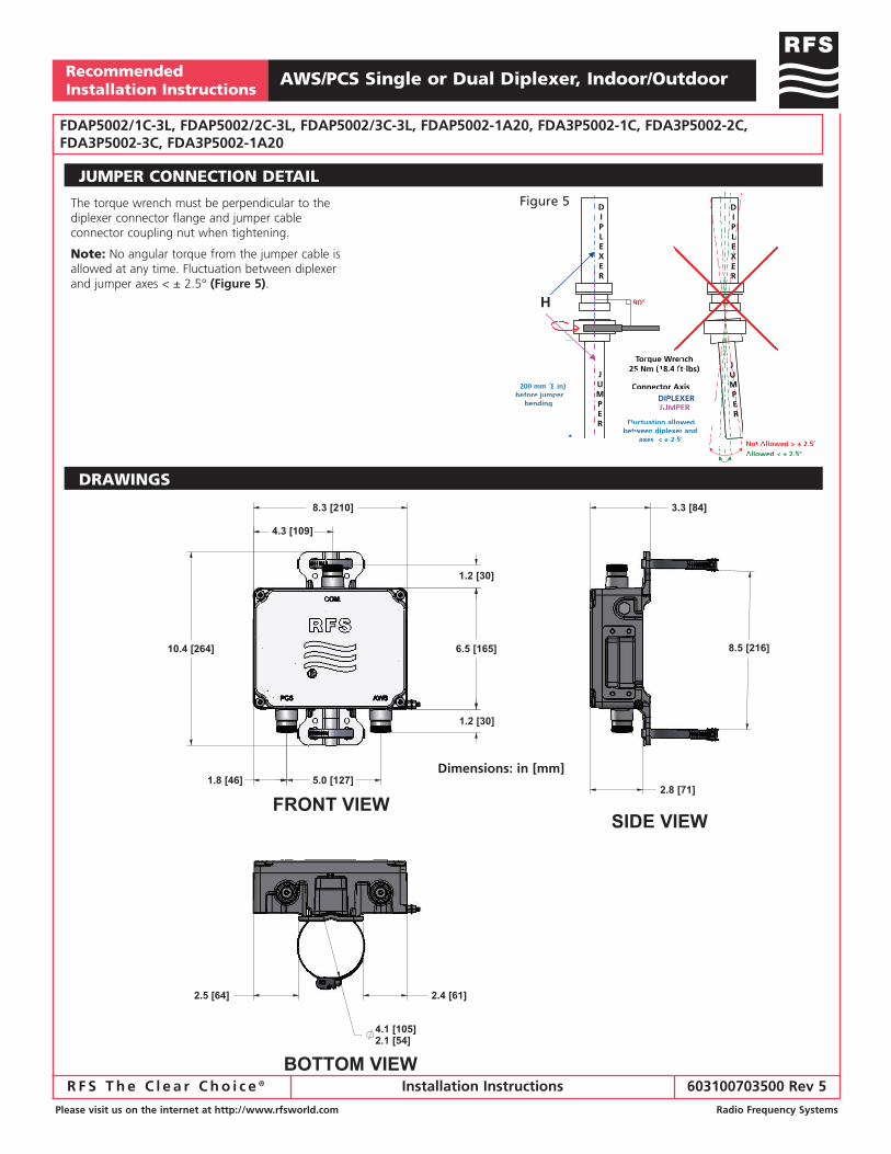
RFS The Clear Choice ® Recommended Installation Instructions Please visit us on the internet at http://www.rfsworld.com Radio Frequency Systems Installation Instructions 603100703500 Rev 5 SINGLE DIPLEXER POLE MOUNT 1. Disconnect RF signals and DC power. 2. Attach the bracket on the wall by means of four screws (not provided) (E-Figure 3). 3. Follow steps 4 to 9 as described above. SINGLE DIPLEXER WALL MOUNT 1. Assemble the (2) diplexers together using the (2) distance plates (F) and the (8) bolt kits (G) in the SEM2-3 Kit (not included). Tighten the bolts with 4 Nm (3 ft-lbs) of torque. 2. Continue installation by following the Pole or Wall Mounting instructions as described above. DUAL DIPLEXER INSTRUCTIONS Recommended Tools: • Allen Wrench 3/16” • Standard Pliers • Torque Wrench Recommended Mounting Positions: • Upright • Upside down • Horizontal with the RFS label facing up Figure 1 C 1. Disconnect RF signals and DC power. 2. Slide the (2) stainless clamps through the rectangular slots of the bracket (A). 3. Fix the clamps/bracket on the pole with 10 Nm (7.5 ft-lbs) torque using an Allen wrench. Be sure the slotted hole is on top. 4. Connect the diplexer to the system using jumper cables. When attaching its 7/16 connector coupling nut to the diplexer connector, it is mandatory that the jumper cable meets the connector straight in line (H-Figure 5). Press the inner part of the jumper cable connector into the diplexer connector and maintain this pressure when turning the coupling nut. Hereby the coupling nut will fit the thread of the female connector correctly and it will run smoothly. Tighten the swivel using your hand. 5. Use a torque wrench to tighten the connector assembly with 25 Nm (18.4 ft-lbs) torque. See Figure 5 on the following page. 6. Grounding is already provided through mounting hardware. If deemed necessary, additional grounding might be obtained by attaching a grounding cable to the external grounding stud (C) on the side of the unit. To do that, tighten the M6 nut and (2) washers with 4 Nm (3 ft-lbs) torque. RFS grounding cables (Model Numbers CA020-2, 2 meter, or CA030-2, 3 meter), or equivalent, may be used. 7. Adjust the length of the ground cable and attach it onto the pole’s ground connection with 4 Nm (3 ft-lbs) torque. 8. Weatherproof the diplexer connections using RFS weatherproofing kits (Model Numbers CTAPE- 1 or WPFG-1) or an equivalent. Follow the instructions supplied with the kit to weatherproof the connectors. 9. Reconnect RF signals and DC power. NOTE 1: Do NOT remove or paint over the breathable vent. (B) NOTE 2: The connector o-ring (D) is integral to sealing and should NOT be cut or scored. Figure 2 Figure 3 Figure 4 A B E E F G D D D E E AWS/PCS Single or Dual Diplexer, Indoor/Outdoor FDAP5002/1C-3L, FDAP5002/2C-3L, FDAP5002/3C-3L, FDAP5002-1A20, FDA3P5002-1C, FDA3P5002-2C, FDA3P5002-3C, FDA3P5002-1A20