Recommended for Grades Four and Five First Edition: 21 March 2005 Developed by: Robert Choma (Fountain Hill Elementary School) Jeanne Deets (Spring Garden Elementary School) Gary DeLeo (Lehigh University, Team Leader) Nina Fink (Lehigh University, Undergraduate Fellow) Sandra Kopp (Lehigh University, Undergraduate Fellow) Steven Sweeney (Lehigh University, Graduate Fellow)
Sandra Kopp (Lehigh University, Undergraduate Fellow)
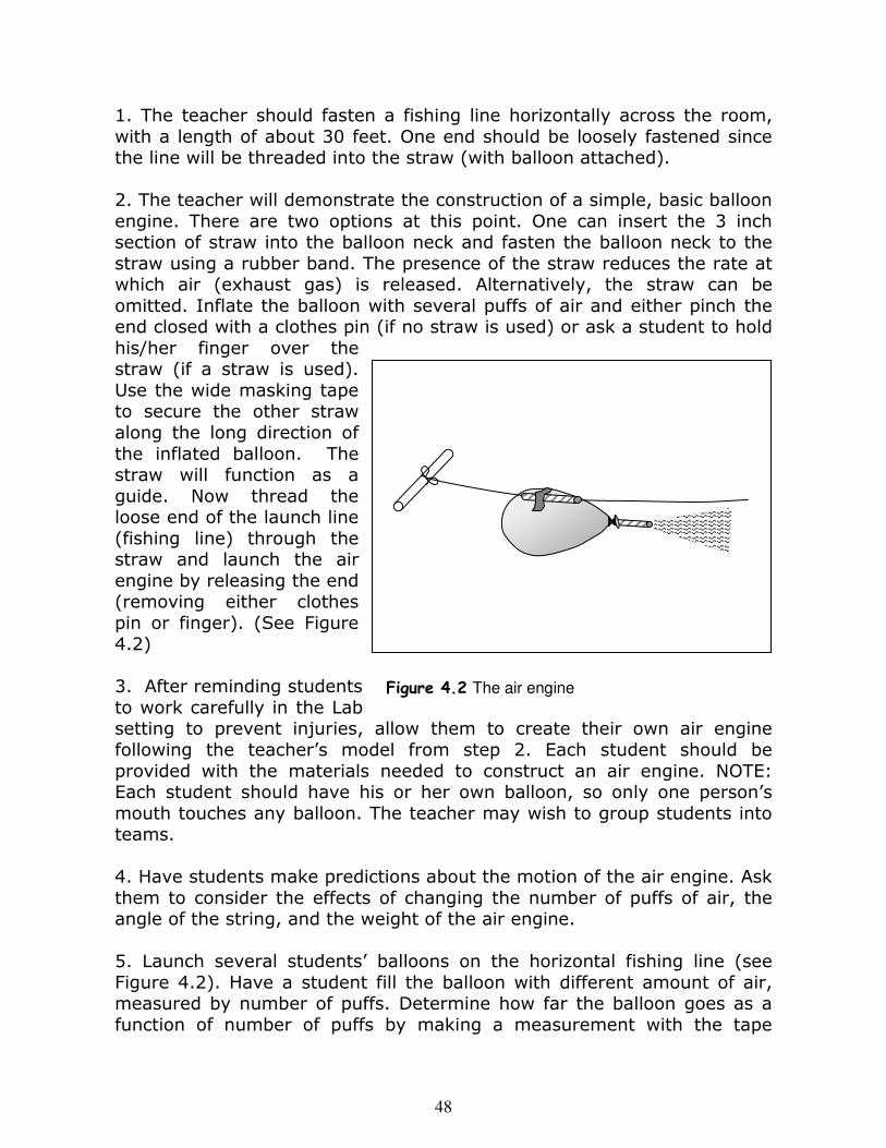
Steven Sweeney (Lehigh University, Graduate Fellow)
2
Support for Program Development: This project is supported by grants to Lehigh University from: The National Science Foundation (grant #0231768)
and
Beall and Linny Fowler, of Bethlehem, Pennsylvania The authors also acknowledge support and encouragement from Lehigh University and the Bethlehem Area School District, Bethlehem, Pennsylvania.
As a Work-in-Progress… The authors would appreciate comments or corrections at any time. A Supplement containing large-sized versions of figures and tables, suitable for copying, is available. Additional materials, especially teacher resources such as worksheets and assessment tools, are under development. The authors would be very grateful to readers willing to share with us any materials developed for use with this guide and provide us with permission to consider them for inclusion in future versions of the Guide or Supplement. The authors may be contacted through G. DeLeo: Gary G. DeLeo, Professor [email protected] (lima-golf-delta-zero) Department of Physics 610-758-3413 (office phone) Lehigh University 610-758-5730 (office FAX) 16 Memorial Dr. E. Bethlehem, PA, 18015
Table of Contents Teacher’s Guide: An Introduction to the Unit ............... 5 General Objectives ................................................................ 5
Overview of the Unit ............................................................... 6 Lesson 1. Introduction to Aviation and the History of Flight .................................................. 11
Key Concepts and Subjects:
Aircraft Basics; History of Aviation; Scaling of Sizes; Ratios and Fractions
a. Aircraft Types and Scale Models ........................................... 11 Activity 1: Scaling Factors and Creation of a
Scale Model ................................................. 14
b. History of Flight and Technology ........................................... 16 Activity 2: Construction of an Aviation Timeline .................. 18 Lesson 2. States of Matter, Heat, and the
Properties of Air ................................................. 20
Key Concepts and Subjects: Atoms and Molecules; Heat and Temperature;
States of Matter; Properties of Gases; Forces and Pressure; Volume
a. States of Matter, Forces, and Heat and Temperature ............... 20
b. Measurements of Area, Volume and Pressure ......................... 24 Activity 3: Measurements of Volume ................................ 26
c. Properties of Gases and the Air ............................................ 28 Activity 4: Air Occupies Space and Exerts Pressure ............. 29
Key Concepts and Subjects: Weight and Density; Buoyancy; Lighter-Than-
Air Vehicles; Atmosphere; Graphs; Respiratory And Circulatory Systems
2
a. Weight and Density ............................................................ 31 Activity 5: Air Has Weight ............................................... 32
b. Buoyancy and Lighter-Than-Air Vehicles ................................ 34 Activity 6: Construction of a Hot Air Balloon ...................... 35
c. Earth’s Atmosphere, Changes with Altitude, and Human Respiratory and Circulatory Systems .................................... 36 Lesson 4. Forces and Motion, Friction, and the Principle of Action and Reaction ......................... 42 Key Concepts and Subjects:
Characterizing Motion; Forces and Motion; Friction and Drag Forces; Law of Action and Reaction; Thrust
and Propulsion; g-Forces; Physiology of Motion and Weightlessness
a. Position, Speed, and Acceleration; Forces and Motion; Friction and Drag Forces .................................................... 42 Activity 7: Construction of a Parachute and
Measurement of Speed .................................. 44
b. Law of Action and Reaction; Thrust and the Air Engine ............ 46 Activity 8: Construction of an Air Engine ........................... 47
c. People in Motion; Forces on the Human Body ......................... 50 Lesson 5. Parts of an Aircraft, and the
Principles of Flight .............................................. 52
Key Concepts and Subjects:
Parts of an Airplane; Forces on an Aircraft; Generation of Lift; Aircraft Control; Design and
Construction; Propellers, Rotors, and Helicopters
a. Forces on an Aircraft .......................................................... 52
b. Wings and Lift .................................................................... 53 Activity 9: Lift From a Wing ............................................ 55
c. Aircraft Parts and Control ..................................................... 57
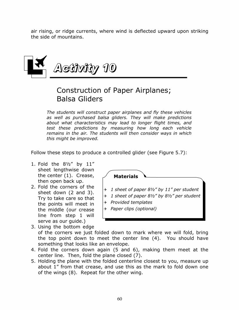
d. Gliders ............................................................................ 59 Activity 10: Construction of Paper Airplanes; Balsa Gliders ... 60
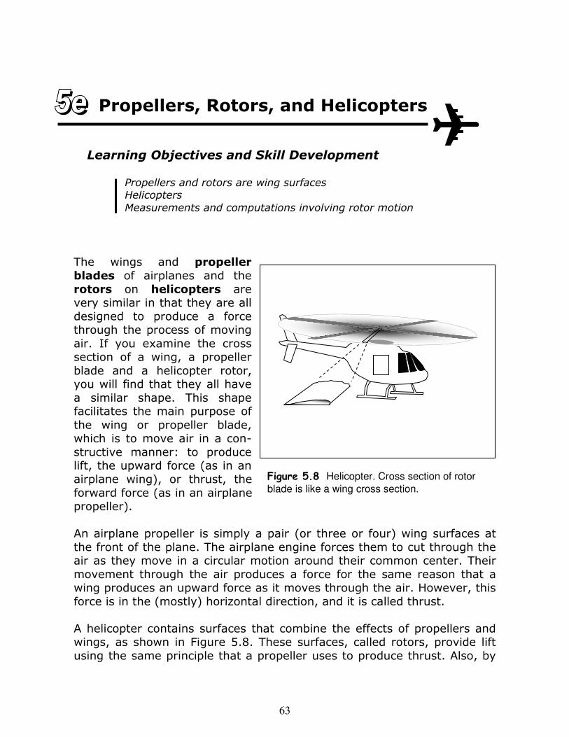
e. Propellers, Rotors, and Helicopters ....................................... 63 Activity11: Rotor Construction; Motion and Analysis ........... 64
3
Lesson 6. Chemical Reactions and Aircraft Engines ............. 67 Key Concepts and Subjects:
Chemical Reactions; Conversion of Heat Energy to Mechanical Energy; Engines; Sound and Hearing
a. Chemical Versus Physical Changes; Chemical Reactions ........... 67 Activity 12: Chemical Reactions ....................................... 68
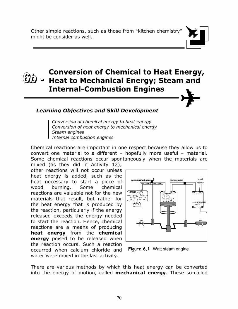
b. Conversion of Chemical to Heat Energy, Heat to Mechanical Energy; Steam and Internal-Combustion Engines ............................................................................. 70 Activity 13: Steam Engine ............................................... 71
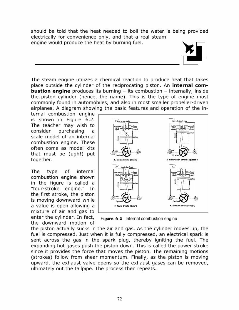
c. Jet Engines and Rocket Engines ........................................... 73
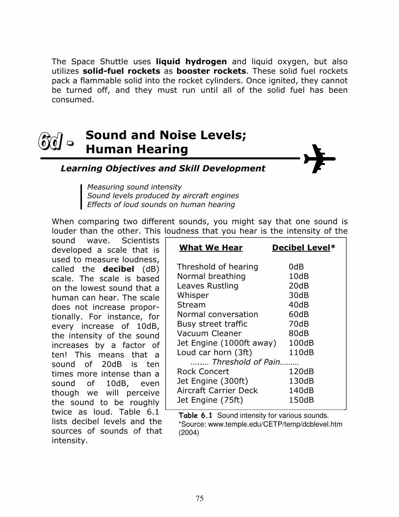
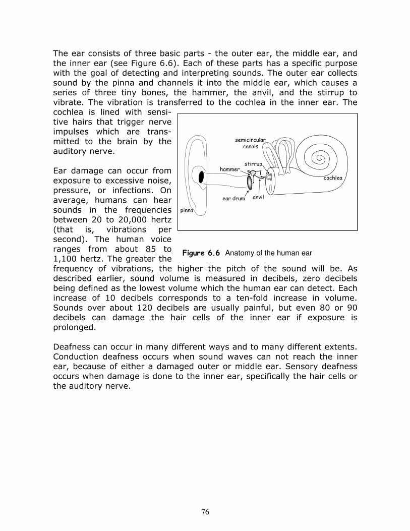
d. Sound and Noise Levels; Human Hearing ............................... 75 Lesson 7. Electricity and Magnetism, Electronic
Devices, and Aircraft Instrumentation ................ 77 Key Concepts and Subjects:
Electric Charge, Electric and Magnetic Forces; Electric Circuits; Electricity Generation; Simple
Instruments; Aircraft Instruments
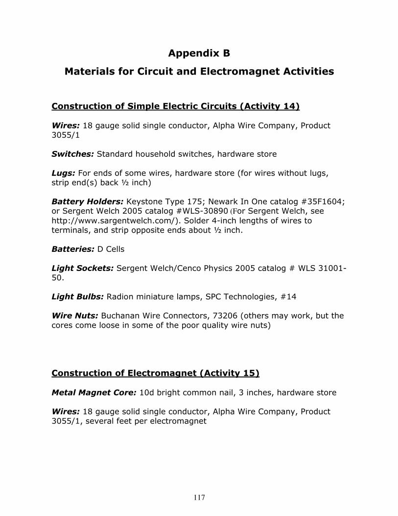
a. Electric Charge; Electric and Magnetic Forces; Electric Circuits ................................................................. 78 Activity 14: Construction of Simple Electric Circuits ............ 80
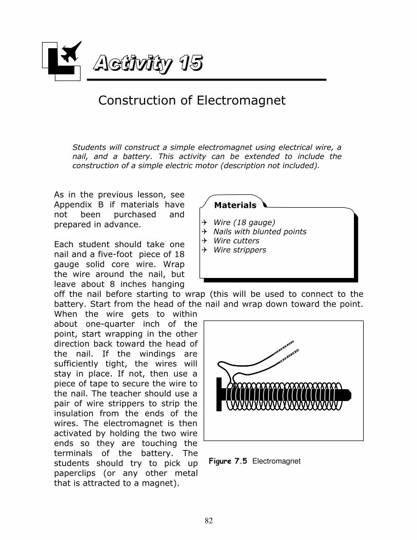
Activity 15: Construction of Electromagnet ........................ 82
b. Conversion of Mechanical to Electrical Energy ......................... 83
c. Simple Electrical Instruments and Aircraft Instruments ............ 84 Lesson 8. Navigation, Maps and Terrain, and Communication .................................................. 87
Key Concepts and Subjects: Magnetic Compass and Heading; Latitude and
Longitude; Navigation; Reading Different Types of Maps; Topographical and False Color Maps;
Radio Communication
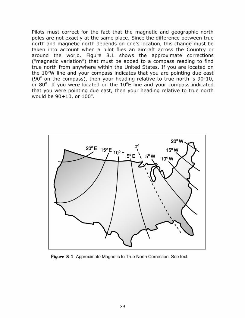
a. Magnetic North, and Directions Using a Magnetic Compass ...... 88
4
b. Latitude and Longitude; Position on the Earth; Navigation ....... 90 Activity 16: Navigating with a Compass, and Using Latitude and Longitude ................................ 90
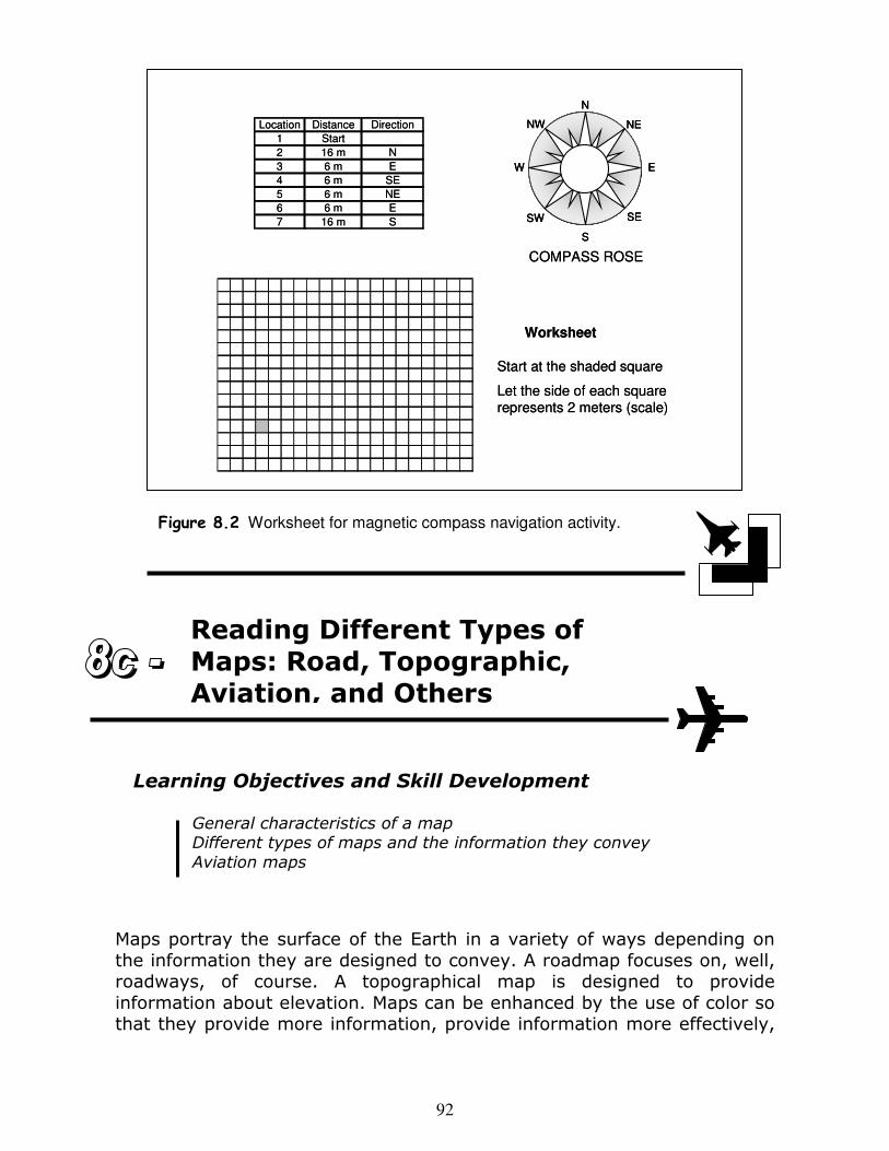
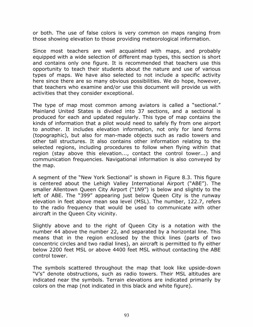
c. Reading Different Types of Maps: Road, Topographic, Aviation, and Others .......................................................... 92
d. Radio Communication ......................................................... 94 Vocabulary and Terminology .............................................. 96
Appendices
A. Aviation Timeline ................................................................ 112
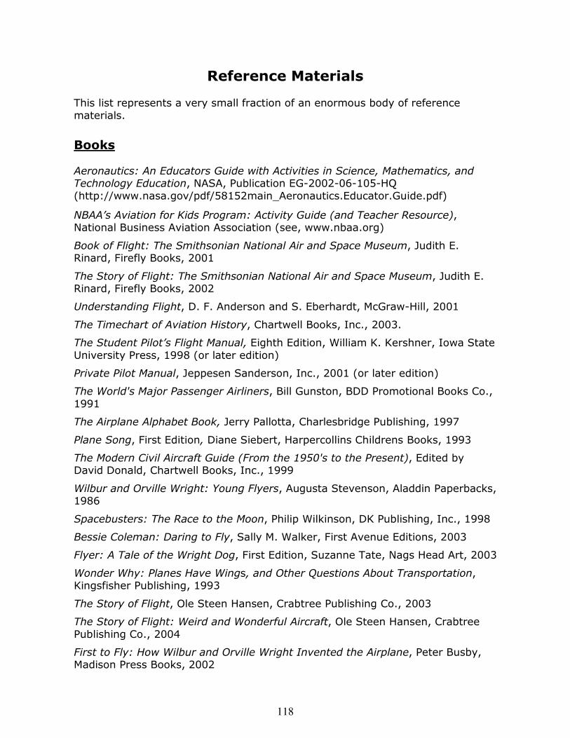
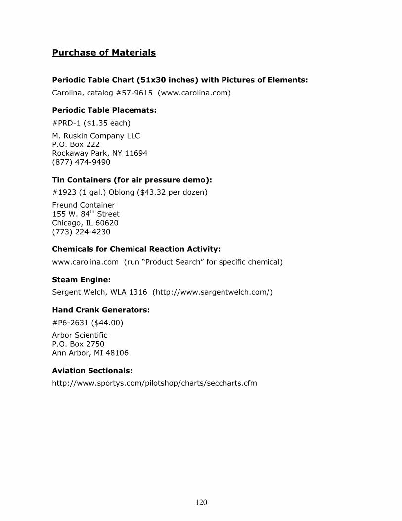
B. Materials for Circuits and Electromagnet Activities ................... 117 Reference Materials ............................................................ 118 State of Pennsylvania Academic Standards for Science and Technology ..................................................... 121
5
Teacher’s Guide
An Introduction to the Unit General Objectives The average child’s natural fascination with science and, at least, tolerance of mathematics deteriorates significantly by the time they start high school. Science becomes “un-cool,” and mathematics intolerable. The fourth-and fifth-grade school years are critical to establishing an interest in science, technology and mathematics that can endure the challenges of middle- and high-school curricula in the face of mounting peer pressures. Before the end of fourth grade, students should have been exposed to a wide range of topics in the natural sciences. They are also developing some basic skills in mathematical and graphical representations that have value in understanding the natural and technological worlds. The approach offered by this document provides an integration of many topics in the natural sciences, as well as technology and mathematics, through the use of a supporting theme that is exciting to children (and teachers) and easily integrated with most curricular content in these disciplines. The theme is aviation. In terms of natural science coverage, this theme lends itself mostly to treatment of the physical sciences. This focus is deliberate since the teaching of physical sciences has been, on average, more difficult for teachers at the elementary-school level than the presentation of life-science subjects. However, selected aspects of life science are presented here, though they deal primarily with human anatomy and physiology. This unit is part of a larger, developing program appropriate to elementary school education. The general program goals are stated below:
• enhance student (and teacher) interest in science, mathematics, and technology
• provide examples and real-world applications to facilitate learning • encourage women and minority students to appreciate and pursue science and technical disciplines
• reveal and emphasize the interconnectedness of seemingly unrelated subjects
6
• identify and enhance awareness of applications of science, mathematics, and basic technologies
• unify two years of school through the narration of an exciting story that encompasses the fourth- and fifth-grade learning experiences
• unite other subjects, ranging from history to geography to medical sciences
This unit is a work in progress. Consequently, some parts are incomplete, and others will require improvement. For example, lesson assessment tools, student worksheets, more extensive web site listings, aviation career and avocation descriptions, and recommendations for connecting with computer technology are planned for future versions. Comments and recommendations by readers and users are strongly encouraged, and that feedback will play an important role in the further development of this work. In what follows, we refer to this presentation as a science unit, subdivided into lessons which include activities. Although this was the original intention of the authors, the project has grown beyond what most educators would consider a unit, though we continue to refer to it as such. It can easily serve as a conventional educational unit if selected parts are used in the classroom. Alternatively, in a somewhat extended form, it could represent the framework for an entire curriculum for fourth-grade (or fifth-grade) science. Regardless of how it is used, this document is written for teachers. So, even if only parts of it see the light of day in the classroom, we hope that the teacher will read it in its entirety. Thus, we anticipate that students will benefit indirectly from this entire work, even if they see only parts of it, through the learning experience and inspiration we have hopefully conveyed to the teacher. Overview of the Unit This unit consists of a sequence of lessons, with most of them designed to occupy one-to-several hours of class time. Each contains one or more activities involving demonstrations and/or active student participation. Each lesson encompasses a collection of related subjects in the natural sciences, with connections as appropriate to mathematics, technology, history, literature, writing, art, geography, and others as they relate to the general theme of aviation.
7
For various reasons, education is rendered more manageable by compartmentalizing academic subjects, even related subjects within the sciences. This organization has a value in terms of scholarly pursuit and the organization of advanced materials. However, it also clouds the oneness of the parts of the natural universe and the human experience. This unit endeavors to break down some of these traditional barriers, and demonstrate the need to cut across traditional disciplinary boundaries when approaching a technical problem, comprehending the natural universe, and understanding social and humanistic implications. It also endeavors to relate concepts and phenomena within the sciences. For example, the atomic theory of matter is directly related to the pressure and temperature of a gas. There is only one nature, and our subdivisions, though useful, are in fact artificial. This unit addresses aspects, some in more depth than others, of the following academic subjects and process skills:
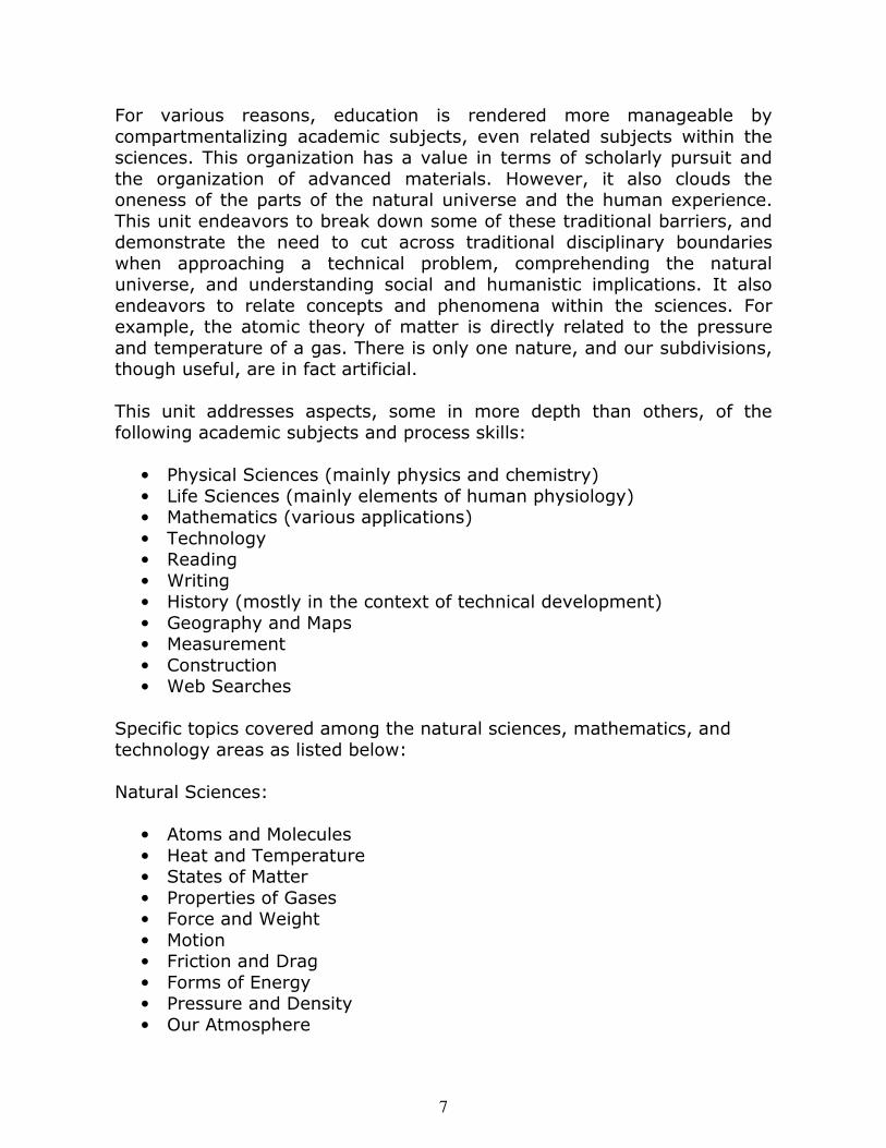
• Physical Sciences (mainly physics and chemistry) • Life Sciences (mainly elements of human physiology) • Mathematics (various applications) • Technology • Reading • Writing • History (mostly in the context of technical development) • Geography and Maps • Measurement • Construction • Web Searches
Specific topics covered among the natural sciences, mathematics, and technology areas as listed below: Natural Sciences:
• Atoms and Molecules • Heat and Temperature • States of Matter • Properties of Gases • Force and Weight • Motion • Friction and Drag • Forms of Energy • Pressure and Density • Our Atmosphere
8
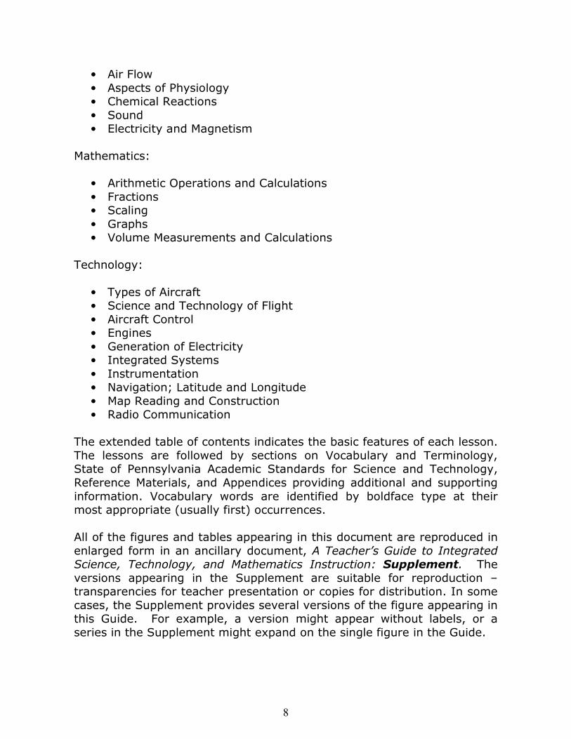
• Air Flow • Aspects of Physiology • Chemical Reactions • Sound • Electricity and Magnetism
Mathematics:
• Arithmetic Operations and Calculations • Fractions • Scaling • Graphs • Volume Measurements and Calculations
Technology:
• Types of Aircraft • Science and Technology of Flight • Aircraft Control • Engines • Generation of Electricity • Integrated Systems • Instrumentation • Navigation; Latitude and Longitude • Map Reading and Construction • Radio Communication
The extended table of contents indicates the basic features of each lesson. The lessons are followed by sections on Vocabulary and Terminology, State of Pennsylvania Academic Standards for Science and Technology, Reference Materials, and Appendices providing additional and supporting information. Vocabulary words are identified by boldface type at their most appropriate (usually first) occurrences. All of the figures and tables appearing in this document are reproduced in enlarged form in an ancillary document, A Teacher’s Guide to Integrated Science, Technology, and Mathematics Instruction: Supplement. The versions appearing in the Supplement are suitable for reproduction – transparencies for teacher presentation or copies for distribution. In some cases, the Supplement provides several versions of the figure appearing in this Guide. For example, a version might appear without labels, or a series in the Supplement might expand on the single figure in the Guide.
9
Although some activities and educational content may be readily omitted in the presentation of this unit, the order of the topics is somewhat important. The unit endeavors to tell a story that weaves together various aspects of our world in a hierarchical manner, with many lessons building on one or more earlier lessons. The story goes as follows: Since aviation is the unifying theme, Lesson 1 introduces the different types of flying vehicles and the history of their development. The concept of scaling is appropriately introduced (e.g., the size of a toy versus the actual aircraft), and provides an opportunity to apply mathematics. A timeline construction permits the consideration of aviation developments in the context of other historically significant events. Since flight relies on the atmosphere and/or the flow of gases (as in a spaceship), Lesson 2 develops the corresponding underlying scientific concepts. Matter is composed of atoms, attractive forces hold them together, and they are always in motion. It is the balance between the tendency of the attractive forces to hold atoms (or molecules) together and the tendency of collisions due to their motions to knock them apart that determines whether a material is a solid, liquid, or gas. Since temperature is a measure of atomic or molecular motion, matter might appear as solid, liquid, or gas depending on temperature. The concepts of pressure, volume, and temperature are developed since these are used to characterize a gas. Lesson 3 applies the basic principles of Lesson 2 to our atmosphere, and develops two applications of these concepts: buoyancy and human respiration. In a hot-air balloon, the force due to gravity – weight – is compensated by the upward force due to buoyancy. Comprehension of the basic physical properties of gases and the particular characteristics of our atmosphere permits an understanding of the laws that govern the suspension of lighter-than-air vehicles. It also provides an opportunity to examine the physiological considerations of human journeys to high altitudes and, in the same spirit, great ocean depths. Lesson 4 introduces a new set of forces, and makes the connection between force and motion. The lesson begins with a characterization of motion and a treatment of the relationship between force and motion. Frictional and drag forces are introduced as examples, and parachutes are understood in this context. The key to propelling a flying vehicle – the law of action and reaction – is developed and applied to the construction of a reaction (jet-like) engine. The force produced by this mechanism is called thrust. Again, this lesson provides an opportunity to investigate
10
physiological dimensions: forces on the human body and weightlessness. It also permits the use of measurement and mathematics in the calculation of physical quantities such as speed. The principles of flight and the parts of an aircraft are introduced in Lesson 5. Previous lessons introduced the forces of weight, drag, and thrust. This lesson completes the set of four forces acting on an aircraft by introducing the lift force. The lesson focuses on lift and wings, but also develops the concept of the propeller and rotor, with an application to helicopters. Again, opportunities for measurements of motion and arithmetic calculations are provided. The students will examine the parts of the aircraft and understand their function in the context of the physical laws developed so far. Lesson 6 is a logical extension of Lesson 5 in that it provides an understanding of the energy and driving forces that actually propel an aircraft (or a spacecraft). Chemical reactions and the concept of energy conversion (chemical to heat to mechanical) are introduced as the basis for understanding engines. Steam, internal combustion, turbojet, turbofan, and rocket engines are presented. The measures of sound intensity – an important aviation issue - are developed and discussed in the context of human hearing. Lesson 7 adds another component to the operation of aircraft and, simultaneously, to the integration of scientific concepts by introducing the physical principles of electricity and magnetism. The lesson begins with a basic understanding of electric charge and electric and magnetic forces. This is followed by an application to electric circuits, and development of the concept of electromagnetic induction used by generators. The lesson ends with a treatment of aircraft instrumentation. Safe and effective aviation requires the ability to navigate and communicate. Therefore, Lesson 8 builds upon navigational needs, and includes magnetic heading, latitude and longitude, and map reading and construction. Students will begin with simple state and road maps, and move to topographic and aviation maps (“sectionals”). Landform considerations are naturally suggested by topographical and aviation maps. The use of radio for communication is treated, along with the special methods of communication used in aviation.
11
This section combines the identification of different types of flying vehicles with the concept of a scale factor. It is common for pictures and models
Key Concepts and Subjects
Aircraft Basics
History of Aviation
Scaling of Sizes
Ratios and Fractions
Sections
1a Aircraft Types and Scale
Models
1b History of Flight and
Technology
Activities
1 Scaling Factors, and
Creation of a Scale Model
2 Construction of an Aviation Timeline
Learning Objectives and Skill Development
Identification and naming of different types of flying vehicles
Concepts of scaling, scale factors, and ratios
Application of fractions and division
Measurements
Construction, drawing, and labeling
Lesson 1 provides an introduction to aircraft and the development of aviation and related technologies, thereby setting the stage for subsequent lessons. The first section pre-sents different types of aircraft, ranging from hot-air balloons to jets and rockets. Aircraft diagrams are used to develop the concepts of size scaling and scale factors. This is followed by a section on the history of flight and re-lated technologies. Students are asked to ex-plore different time periods in the develop-ment of aviation through the use of text and web-based readings, and produce written reports. A timeline of aviation and related technologies is constructed as a class activity. The writing assignment and timeline, started during Lesson 1, can continue through later lessons as appropriate to completion.
Overview
Aircraft Types and Scale Models
12
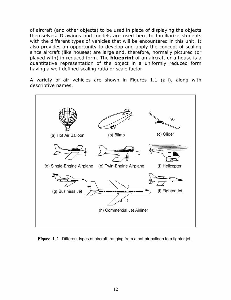
of aircraft (and other objects) to be used in place of displaying the objects themselves. Drawings and models are used here to familiarize students with the different types of vehicles that will be encountered in this unit. It also provides an opportunity to develop and apply the concept of scaling since aircraft (like houses) are large and, therefore, normally pictured (or played with) in reduced form. The blueprint of an aircraft or a house is a quantitative representation of the object in a uniformly reduced form having a well-defined scaling ratio or scale factor. A variety of air vehicles are shown in Figures 1.1 (a-i), along with descriptive names.
Figure 1.1 Different types of aircraft, ranging from a hot-air balloon to a fighter jet.
13
As mentioned earlier, larger reproductions of these figures are provided in the Supplement for the purpose of constructing transparencies and engaging the class in discussion. Students should be asked to comment on each of the figures: Have they ever seen this before? What is interesting about it? How is each different from the previous vehicles? Have they ever flown in one of these? Which are lighter-than-air vehicles and heavier-than-air vehicles? … etc. Students should be asked to watch for these and report their observations during later classes. The teacher should next show students a scale model of a jet or airplane (a toy), and ask how this is different from the real vehicle. Figure 1.2 of the Supplement contains scale drawings of three types aircraft, labeled with actual dimensions and the corresponding scale used in constructing the drawings. These figures are suitable for making a transparency. (The corresponding figure in this document is provided for convenience only; the scale factor is not correct since it is reduced.) The teacher should describe the relationship between the actual dimensions and the scale-model dimensions. In this example, one inch corresponds to forty feet, or 480 inches. Hence the “scale” is 1:480. Describe the meaning of this scale factor in the context of ratios and fractions. Describe the process by which one would take the blueprint lengths in inches and multiply them by 480 in order to determine the actual dimensions in inches. One could then divide by 12 to convert the actual dimensions to feet, or by 36 to convert to yards. One can also go in the other direction by beginning with the actual dimensions and applying a suitable scale factor to create a scale model. For example, if the wingspan on the actual aircraft is 20 feet, and one wishes this to be 4 feet on the scale model, one needs to scale the dimensions down by a factor of 20/4 = 5. Hence the scaling factor is 5:1. This sets the stage for Activity 1.
Scale: 1 inch = 40 feet
40 feet
230 feet
Scale Factor 1:480200 feet
Boeing 747
100 feet
24 feet
Boeing 737
Piper Warrior II
Scale: 1 inch = 40 feet
40 feet
230 feet
Scale Factor 1:480200 feet
Boeing 747
100 feet
24 feet
Boeing 737
Piper Warrior II
Figure 1.2 Scale-diagrams of Boeing 747,
Boeing 737, and Piper Warrior II. Note: Scale factor is correct only for the enlarged Supplement version. Used with permission from Eduardo Escalona (see references).
14
� Tape measures and/or rulers
� Calculators
� Masking tape, or large posters or paper with crayons
� Copies of Supplement Figures 1.2 and 1.3
Materials
Scaling Factors and Creation of a
Scale Model
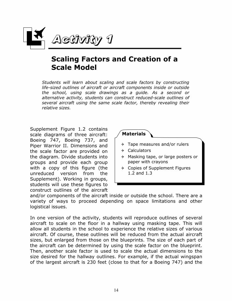
Supplement Figure 1.2 contains scale diagrams of three aircraft: Boeing 747, Boeing 737, and Piper Warrior II. Dimensions and the scale factor are provided on the diagram. Divide students into groups and provide each group with a copy of this figure (the unreduced version from the Supplement). Working in groups, students will use these figures to construct outlines of the aircraft and/or components of the aircraft inside or outside the school. There are a variety of ways to proceed depending on space limitations and other logistical issues. In one version of the activity, students will reproduce outlines of several aircraft to scale on the floor in a hallway using masking tape. This will allow all students in the school to experience the relative sizes of various aircraft. Of course, these outlines will be reduced from the actual aircraft sizes, but enlarged from those on the blueprints. The size of each part of the aircraft can be determined by using the scale factor on the blueprint. Then, another scale factor is used to scale the actual dimensions to the size desired for the hallway outlines. For example, if the actual wingspan of the largest aircraft is 230 feet (close to that for a Boeing 747) and the
Students will learn about scaling and scale factors by constructing
life-sized outlines of aircraft or aircraft components inside or outside the school, using scale drawings as a guide. As a second or
alternative activity, students can construct reduced-scale outlines of several aircraft using the same scale factor, thereby revealing their relative sizes.
15
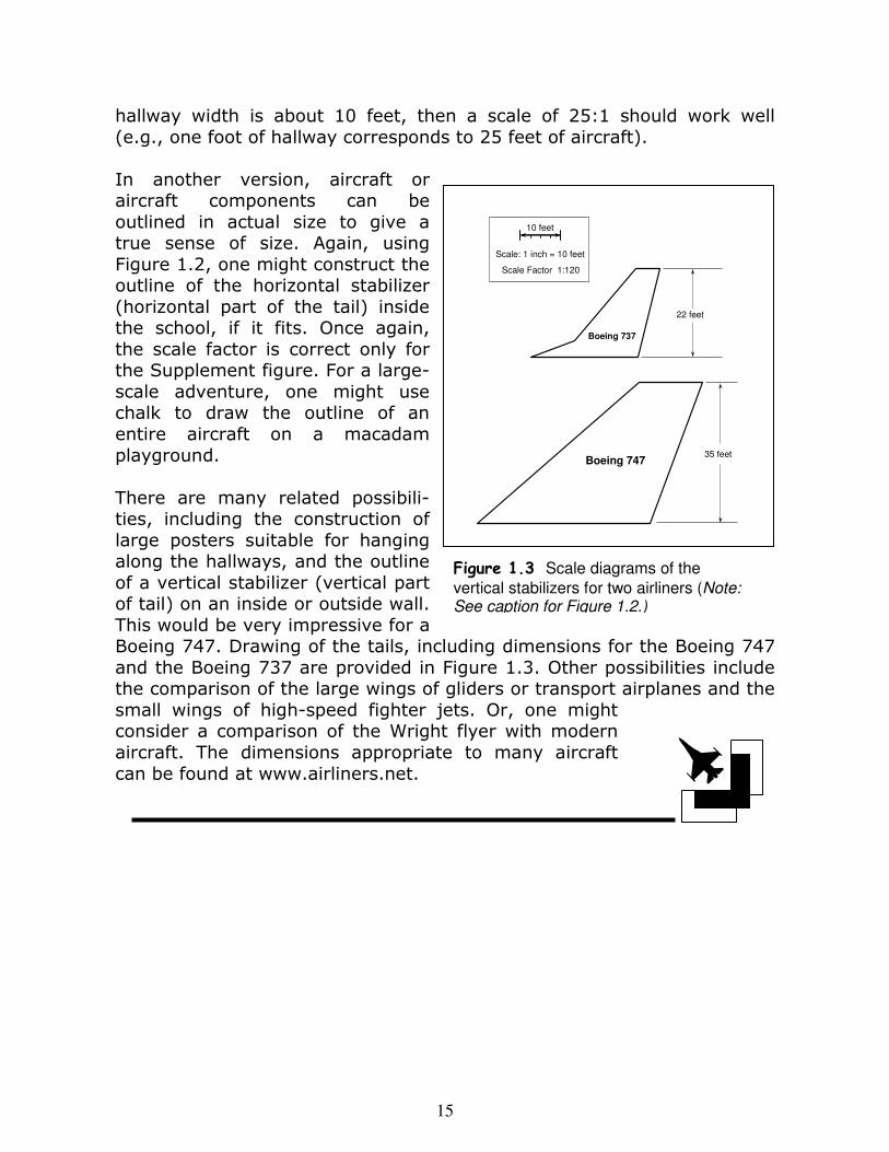
hallway width is about 10 feet, then a scale of 25:1 should work well (e.g., one foot of hallway corresponds to 25 feet of aircraft). In another version, aircraft or aircraft components can be outlined in actual size to give a true sense of size. Again, using Figure 1.2, one might construct the outline of the horizontal stabilizer (horizontal part of the tail) inside the school, if it fits. Once again, the scale factor is correct only for the Supplement figure. For a large-scale adventure, one might use chalk to draw the outline of an entire aircraft on a macadam playground. There are many related possibili-ties, including the construction of large posters suitable for hanging along the hallways, and the outline of a vertical stabilizer (vertical part of tail) on an inside or outside wall. This would be very impressive for a Boeing 747. Drawing of the tails, including dimensions for the Boeing 747 and the Boeing 737 are provided in Figure 1.3. Other possibilities include the comparison of the large wings of gliders or transport airplanes and the small wings of high-speed fighter jets. Or, one might consider a comparison of the Wright flyer with modern aircraft. The dimensions appropriate to many aircraft can be found at www.airliners.net.
35 feetBoeing 747
22 feet
Boeing 737
Scale: 1 inch = 10 feet
10 feet
Scale Factor 1:120
Figure 1.3 Scale diagrams of the
vertical stabilizers for two airliners (Note: See caption for Figure 1.2.)
16
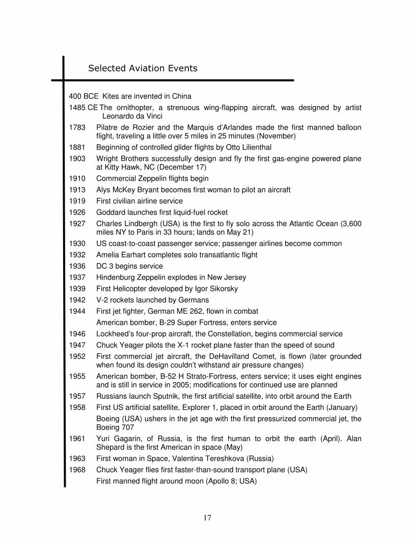
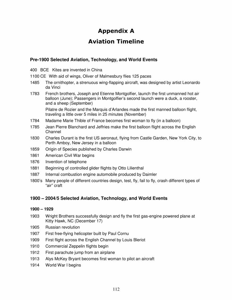
In this section, students are asked to place the different types of flying vehicles in an historical context. Space travel may be included at the discretion of the teacher. The teacher provides an overview as described below, and this is followed by instructions for the reading, web-search, and writing assignments that accompany Activity 2. Activity 2 is started during this lesson, but continues through completion with class time provided over several weeks. A timeline is a number line that shows important events in a period of history. It is an effective way to organize information so that it can be understood at a glance. Timelines may be constructed in many different ways. A Straight Timeline shows events that have taken place, the order in which they occurred, and the relative amount of time between events. A Tiered Timeline includes basic facts that connect with the date. A Ribbon Timeline uses a curved line that runs back and forth, enabling the presentation of long periods of time with minimum use of page space. A ribbon timeline would be suggested for cases where longer periods of time are represented. A summary of some of the important events in the history of flight and aviation-related technology is provided below. A more comprehensive list that includes other historical events as well is provided in Appendix A. Using these, the teacher can provide an overview of the history of aviation. Either of these tables, the long or short versions, can be used as a starting point for class discussion or web searches for the timeline construction of Activity 2.
History of Flight and Technology
Learning Objectives and Skill Development
Historical developments in aviation and related technologies
Historical context of aviation events
Timeline presentation of historical events
Reading, web searches, writing
Fractions and division
17
Selected Aviation Events
400 BCE Kites are invented in China
1485 CE The ornithopter, a strenuous wing-flapping aircraft, was designed by artist Leonardo da Vinci
1783 Pilatre de Rozier and the Marquis d’Arlandes made the first manned balloon flight, traveling a little over 5 miles in 25 minutes (November)
1881 Beginning of controlled glider flights by Otto Lilienthal
1903 Wright Brothers successfully design and fly the first gas-engine powered plane at Kitty Hawk, NC (December 17)
1910 Commercial Zeppelin flights begin
1913 Alys McKey Bryant becomes first woman to pilot an aircraft
1919 First civilian airline service
1926 Goddard launches first liquid-fuel rocket
1927 Charles Lindbergh (USA) is the first to fly solo across the Atlantic Ocean (3,600 miles NY to Paris in 33 hours; lands on May 21)
1930 US coast-to-coast passenger service; passenger airlines become common
1932 Amelia Earhart completes solo transatlantic flight
1936 DC 3 begins service
1937 Hindenburg Zeppelin explodes in New Jersey
1939 First Helicopter developed by Igor Sikorsky
1942 V-2 rockets launched by Germans
1944 First jet fighter, German ME 262, flown in combat
American bomber, B-29 Super Fortress, enters service
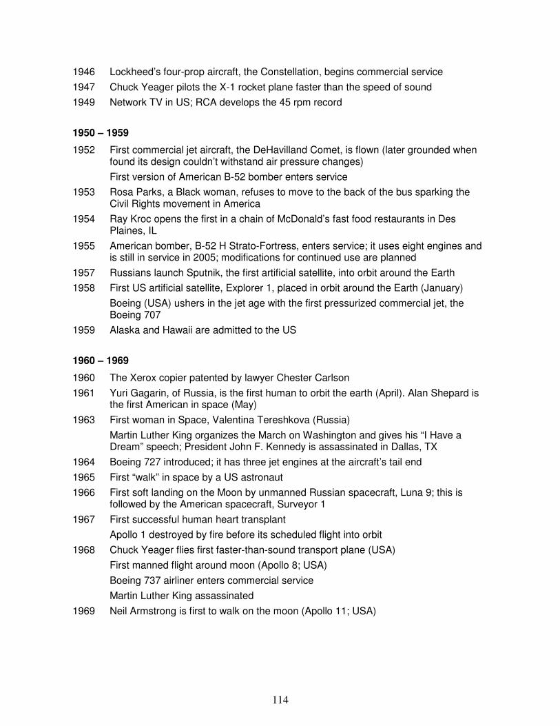
1946 Lockheed’s four-prop aircraft, the Constellation, begins commercial service
1947 Chuck Yeager pilots the X-1 rocket plane faster than the speed of sound
1952 First commercial jet aircraft, the DeHavilland Comet, is flown (later grounded when found its design couldn’t withstand air pressure changes)
1955 American bomber, B-52 H Strato-Fortress, enters service; it uses eight engines and is still in service in 2005; modifications for continued use are planned
1957 Russians launch Sputnik, the first artificial satellite, into orbit around the Earth
1958 First US artificial satellite, Explorer 1, placed in orbit around the Earth (January)
Boeing (USA) ushers in the jet age with the first pressurized commercial jet, the Boeing 707
1961 Yuri Gagarin, of Russia, is the first human to orbit the earth (April). Alan Shepard is the first American in space (May)
1963 First woman in Space, Valentina Tereshkova (Russia)
1968 Chuck Yeager flies first faster-than-sound transport plane (USA)
First manned flight around moon (Apollo 8; USA)
18
1969 Neil Armstrong is first to walk on the moon (Apollo 11; USA)
1970 Boeing 747 Jumbo Jet enters service
1976 French made SST Concorde crosses 3600 miles, New York to Paris, in 3 hours traveling subsonic over land and increasing to mach 2, a speed of 1400 mph, over the ocean
1977 Gossamer Condor becomes the first human-powered aircraft
1981 First space shuttle launched at the Kennedy Space Center, Cape Canaveral, FL
1983 Sally Ride becomes the first American woman in space
1986 Voyager is piloted by Jeanna Yeager and Dick Rutan, making the first trip around the world without refueling
1993 Victoria Van Meter becomes the youngest girl to fly across the US at age 11
1995 Boeing 777 jetliner enters service
Galileo becomes first spacecraft to orbit Jupiter
1999 First nonstop balloon flight around world is completed in 20 days
2000 First crew of American and Russian astronauts occupies the International Space Station
2003 Space Shuttle Columbia is destroyed during re-entry
2004 Cassini becomes the first spacecraft to orbit Saturn; the Huygens lander is released in December and lands on the moon, Titan, in January 2005
2005 Steven Fosset completes the first nonstop solo flight around the world without refueling
At this stage, students should be assigned different periods, about which they will read (books and web), write, and use in contributing to the class timeline of Activity 2.
In a class project, the students will construct a large timeline
containing major aviation events. The timeline can include other technical developments and historical events as well.
Construction of an Aviation Timeline
19
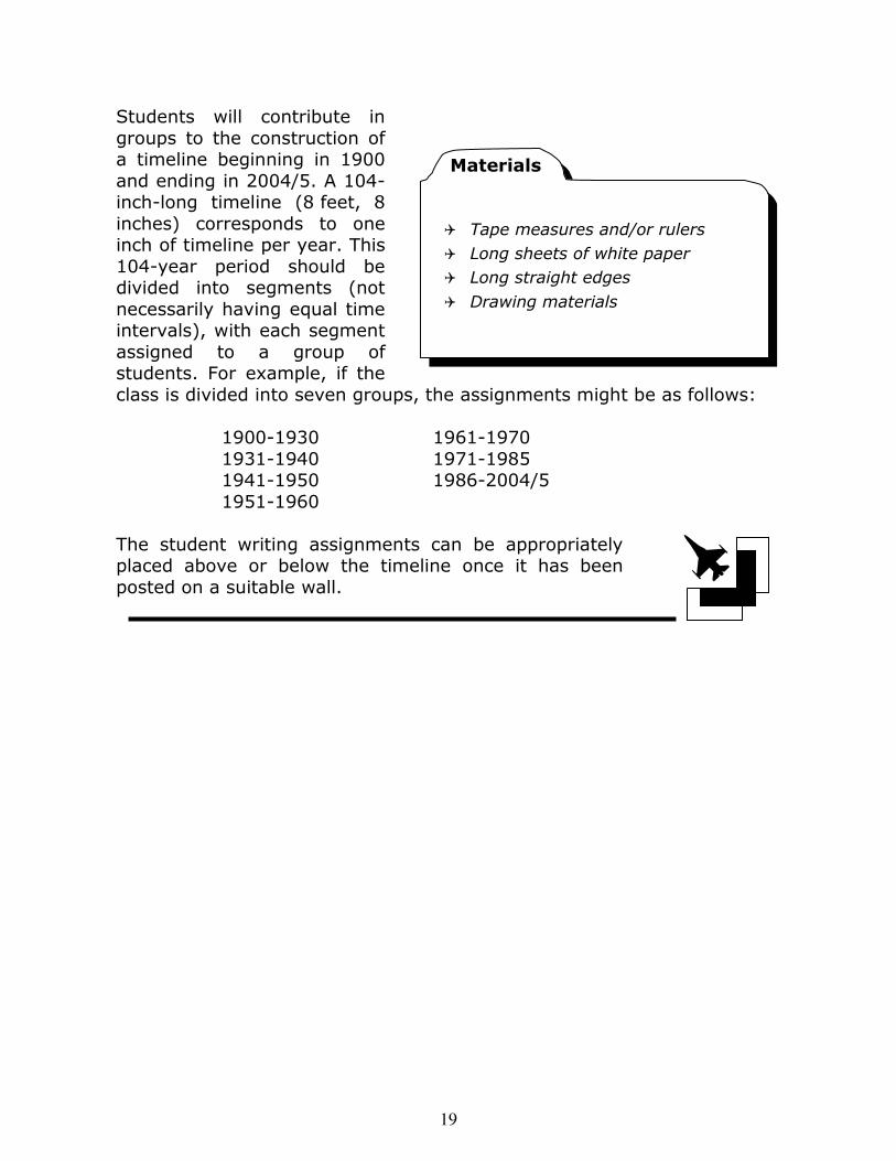
� Tape measures and/or rulers
� Long sheets of white paper
� Long straight edges
� Drawing materials
Materials
Students will contribute in groups to the construction of a timeline beginning in 1900 and ending in 2004/5. A 104-inch-long timeline (8 feet, 8 inches) corresponds to one inch of timeline per year. This 104-year period should be divided into segments (not necessarily having equal time intervals), with each segment assigned to a group of students. For example, if the class is divided into seven groups, the assignments might be as follows: 1900-1930 1961-1970 1931-1940 1971-1985 1941-1950 1986-2004/5 1951-1960 The student writing assignments can be appropriately placed above or below the timeline once it has been posted on a suitable wall.
20
Key Concepts and Subjects
Atoms and Molecules
Heat and Temperature
States of Matter
Properties of Gases
Forces and Pressure
Volume
Sections
2a States of Matter, Forces,
Heat and Temperature
2b Measurements of Area,
Volume and Pressure
2c Properties of Gases and the
Air
Activities
3 Measurements of Volume
4 Air Occupies Space and Exerts Pressure
Learning Objectives and Skill Development
Atoms, elements, compounds and molecules
Periodic Table of the Elements
Concept of force; Electrostatic forces hold atoms/molecules together
Atoms are always in motion; Temperature is a measure of this motion
States of matter are determined by a balance between attractive
forces and collisions due to motion
Air travel relies on the presence of our atmosphere, and even rocket propulsion depends on the expulsion of hot gases. Lesson 2 develops states of matter, and focuses on gases. Meaning is provided to the terms heat and temperature, and the states of matter are understood in terms of the motion of atoms and molecules. Since gases are characterized by pressure, volume, and temperature, students are introduced to these concepts and measurements of force and area (since pressure is force per unit surface area), as well as volume and temperature.
In the first section, temperature is related to the motions of the atoms. This motion along with the forces that hold atoms together determine the physical state of matter at a given temperature. The concept of force is introduced here. Meas-urements of area, volume, and pressure are de-scribed in the second section. The measurement of volume is described for solids, liquids, and gases. Pressure is then defined in terms of forces and areas. These concepts are applied to air in the final section of this lesson.
Overview
States of Matter, Forces, and
Heat and Temperature
21
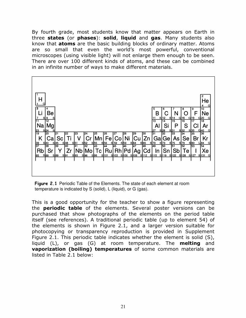
By fourth grade, most students know that matter appears on Earth in three states (or phases): solid, liquid and gas. Many students also know that atoms are the basic building blocks of ordinary matter. Atoms are so small that even the world’s most powerful, conventional microscopes (using visible light) will not enlarge them enough to be seen. There are over 100 different kinds of atoms, and these can be combined in an infinite number of ways to make different materials.
This is a good opportunity for the teacher to show a figure representing the periodic table of the elements. Several poster versions can be purchased that show photographs of the elements on the period table itself (see references). A traditional periodic table (up to element 54) of the elements is shown in Figure 2.1, and a larger version suitable for photocopying or transparency reproduction is provided in Supplement Figure 2.1. This periodic table indicates whether the element is solid (S), liquid (L), or gas (G) at room temperature. The melting and vaporization (boiling) temperatures of some common materials are listed in Table 2.1 below:
Li
Na
K
Rb
Ne
Ar
Kr
Xe
Be
Mg
Ca
Sr
F
Cl
Br
I
Sc
Y
Ti
Zr
V
Nb
Cr
Mo
Mn
Tc
Fe
Ru
Co
Rh
Ni
Pd
Cu
Ag
Zn
Cd
Ga
In
Ge
Sn
As
Sb
Se
Te
B
Al
C
Si
N
P
O
S
H He
6
11
87 9 10
G
S
S
5
13 14 15 16 17 18
36
5453
3534
5251
333231
49 5048
3029
47
2
12 14 16 19 20
4
27 28 31 32 35 40
70 73 75 79 80 84
115 119 122 128 127 131
G G GS
SS S S G G
G
L G
G
S SS
SS S S S
656459595655
112108106103101
28272625
46454443
98 SSSSSS
S S S S S S
242322212019
37 38 39 40 41 42
969391898885
525148454039
12
43
11
24
97
23
3
1
1
SS
S S
SS
SS SSS
S
S
SSS
G
Figure 2.1 Periodic Table of the Elements. The state of each element at room
temperature is indicated by S (solid), L (liquid), or G (gas).
22
Substance Melting (oF) Boiling (oF)
Nitrogen -344 -321 Alcohol -179 174 Mercury -38 675 Water 32 212 Sugar 365 none (decomposes) Lead 621 3,171 Salt 1,474 2,575 Iron 2,795 4,982 Sapphire 3,713 5,396 Diamond 6,422 8,721
Table 2.1 Melting and boiling points of materials
Engage the students in a discussion by asking them to describe some of the more familiar elemental materials (e.g., iron, silver, helium, …) ap-pearing on the period table. Ask them to explain why so many common materials seem to be missing from the table (e.g., water, salt, …). The materials missing from the table are not elements, but rather compound mate-rials (compounds) com-posed of combinations of the basic elements. For example, a water unit (molecule) consists of two hydrogen atoms and one oxygen atom stuck to-gether, as shown in Figure 2.2, along with some other molecules. When atoms are rearranged to create different molecules, this is called a chemical reaction, or a chemical change. This is treated in a later lesson. Here, we focus on physi-cal changes: the changes of a material – elemental or compound – between the solid, liquid, and gas states.
Hydrogen AtomOxygen AtomCarbon Atom
O2 - Oxygen as We Breath It
CO2 - Carbon Dioxide; What We Exhale
H2O - Water; What We Drink
CH4 - Methane; From Natural Gas,
Used as Fuel
Figure 2.2 Various molecules.
23
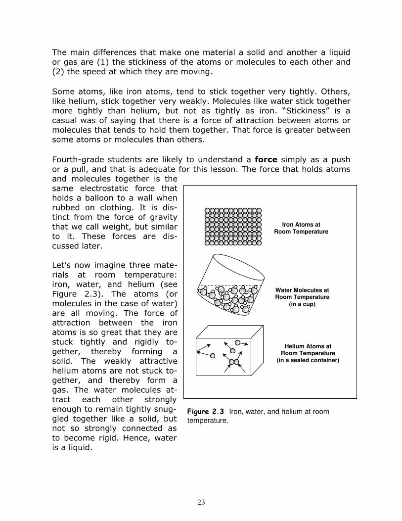
The main differences that make one material a solid and another a liquid or gas are (1) the stickiness of the atoms or molecules to each other and (2) the speed at which they are moving. Some atoms, like iron atoms, tend to stick together very tightly. Others, like helium, stick together very weakly. Molecules like water stick together more tightly than helium, but not as tightly as iron. “Stickiness” is a casual was of saying that there is a force of attraction between atoms or molecules that tends to hold them together. That force is greater between some atoms or molecules than others. Fourth-grade students are likely to understand a force simply as a push or a pull, and that is adequate for this lesson. The force that holds atoms and molecules together is the same electrostatic force that holds a balloon to a wall when rubbed on clothing. It is dis-tinct from the force of gravity that we call weight, but similar to it. These forces are dis-cussed later. Let’s now imagine three mate-rials at room temperature: iron, water, and helium (see Figure 2.3). The atoms (or molecules in the case of water) are all moving. The force of attraction between the iron atoms is so great that they are stuck tightly and rigidly to-gether, thereby forming a solid. The weakly attractive helium atoms are not stuck to-gether, and thereby form a gas. The water molecules at-tract each other strongly enough to remain tightly snug-gled together like a solid, but not so strongly connected as to become rigid. Hence, water is a liquid.
Iron Atoms at Room Temperature
Water Molecules at Room Temperature
(in a cup)
Helium Atoms at Room Temperature
(in a sealed container)
Figure 2.3 Iron, water, and helium at room
temperature.
24
The motion of the atoms – the speed of the atoms – depends on the temperature of the material. If we take a piece of iron, for example, and make it very hot, it will melt and change to a liquid. This is because the iron atoms move much faster at higher temperatures. In fact, what we perceive as temperature is mostly a measure of how fast the atoms are moving. If we make the temperature much higher, the iron atoms become completely unstuck and the material vaporizes, becoming a gas. (Note: temperature depends on the mass of the atoms or molecules that constitute the gas as well as their speed; but that is not critical here.) Hence, the state of matter is determined by a competition between the strength of the attractive forces that attempt to hold the atoms or molecules together (depends on the material) and the violent collisions due to the high-speed motions that tend to break them apart (depends on temperature). This is like trying to get Velcro balls to stick to a cloth target. They do not stick if they are thrown too fast (like a high temperature), and the situation is worse if the Velcro is worn (like a weak bond). Heat is distinct from but related to temperature. Temperature is a measure of the condition of a material, related to the average speed of the constituent atoms or molecules. Heat is a form of energy that can be conveyed to a material, leading to a rise in the material’s temperature. However, there are other forms of energy that may be delivered to the material, and, therefore, other ways that it might be heated.
Measurements of Area, Volume
and Pressure
Learning Objectives and Skill Development
Measurements and calculations of area and volume
Pressure as a force per unit area due to collisions
Air pressure
Arithmetic calculation
25
As developed in the last section, the atoms or molecules comprising a gas (in fact, any material) are in constant motion and continually bouncing off one another. If the gas is confined to a container, atoms and molecules not only run into other atoms and molecules, but they also bounce off the inside surfaces of the container. The force exerted over a unit of surface area (say, a square inch) by these collisions is called pressure. Pressure can apply to solids, liquids, and gases. Pressure is simply the force exerted on a surface, measured in pounds, divided by the area of that surface, measured, say, in square inches. For example, if a student weighs 60 pounds, and her weight is distributed over the surface of a chair roughly 10 inches by 10 inches across – or 100 square inches – the student is exerting a pressure of 60/100 = 0.6 pounds per square inch on the chair. This is illustrated by Figure 2.4. The teacher should consider a variety of examples: If you were stuck on thin ice, you should lie flat to distribute your weight over a greater area so the force on each square inch of ice is less. Your car should have airbags to distribute the force of impact over a greater area. Etc… The teacher should demonstrate the measurement and calculation of some area within the classroom. Activity 3 involves measurements of volumes. Prior to Activity 3, the teacher might wish to have the class – as a whole or in groups – calculate the areas of some rectangular objects in the room, or the area of the classroom itself. It is instructive to show how the areas of two objects having different shapes, like a square and a rectangle, can have the same value, One might also show how the areas of non-rectangular objects can be estimated by dividing them into square or rectangular parts.
Child’s Rear
Each Square Inch of Child’s Rear
End
pounds 0.6 0.6 0.6 0.6
All Adds Up to 60 Pounds
Figure 2.4 Illustration of pressure exerted by
a 60 pound child if distributed over a 100 square inch area.
26
� Rulers (in centimeters and millimeters)
� Tape measure
� Calculators
� Solid objects of rectangular form
� Irregularly shaped objects that sink in water (like rocks)
� Water-tight containers with rectangular bases (like a paperclip holder)
� Empty one-quart milk containers
(rectangular)
� Pie tins
Materials
Working in groups, have students measure the lengths of the three sides of their rectangular solids in units of centimeters, measuring the dimensions to a tenth of a centimeter (e.g., 4.7 cm). They should multiply the three numbers together to determine the volume of the solid in cubic centimeters. If the objects are roughly the same size, but with different dimensions, the teacher may wish to ask students to guess which of them has the larger volume before sharing the results. Finally, as a class activity, use the tape measure to measure the length, width, and height of the classroom (if roughly rectangular), and determine its volume. The volume of a liquid can be determined by placing it in a rectangular container and measuring the dimensions as before. Demonstrate this for the class by placing water in a rectangular milk carton with the top removed. The teacher may wish to relate this to household liquid volume measures and kitchen measuring cups. Furthermore, this provides an opportunity to discuss different types of measure and the conversion between units. For example, 1 liter represents 1000 cubic centimeters. This would be the volume of a cubic object, with sides equal to 10 cm. Have the students measure the three dimensions of a milk container in
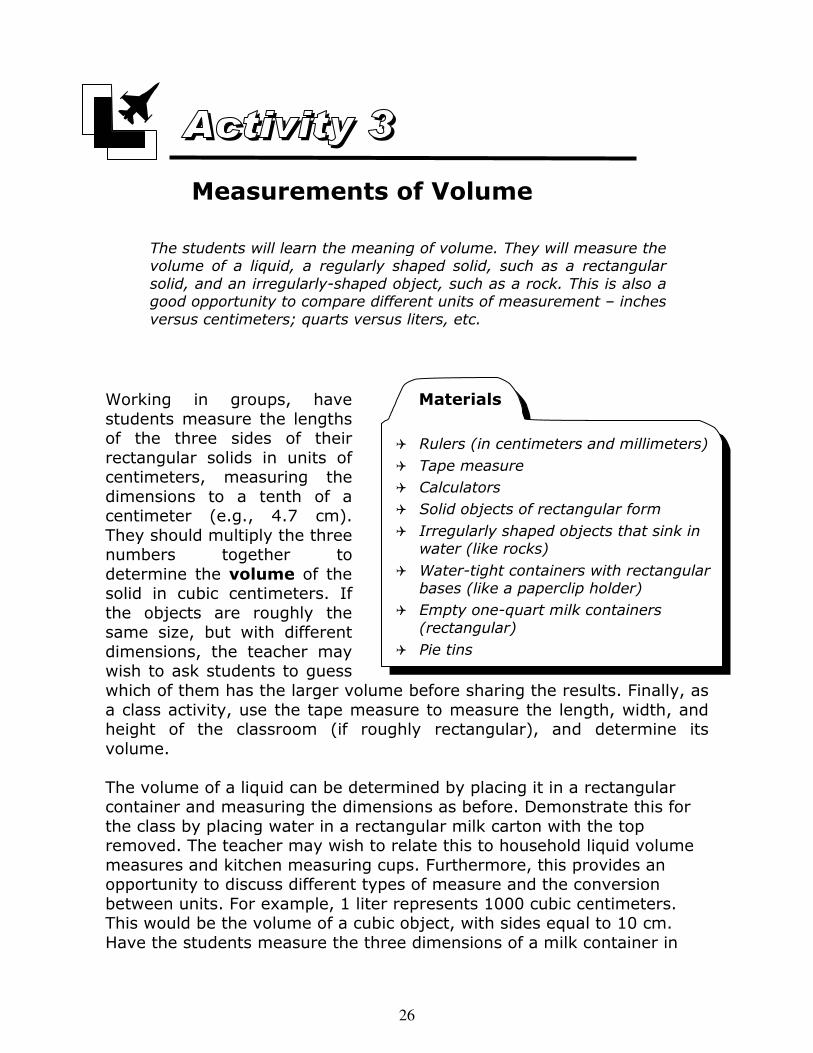
The students will learn the meaning of volume. They will measure the volume of a liquid, a regularly shaped solid, such as a rectangular
solid, and an irregularly-shaped object, such as a rock. This is also a good opportunity to compare different units of measurement – inches
versus centimeters; quarts versus liters, etc.
Measurements of Volume
27
centimeters, and compute the volume in liters, thereby demonstrating that one quart is approximately 0.96 liters (close to a liter).
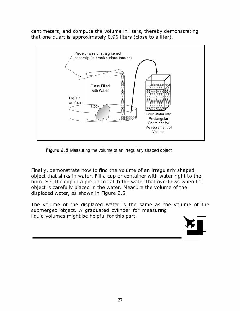
Finally, demonstrate how to find the volume of an irregularly shaped object that sinks in water. Fill a cup or container with water right to the brim. Set the cup in a pie tin to catch the water that overflows when the object is carefully placed in the water. Measure the volume of the displaced water, as shown in Figure 2.5. The volume of the displaced water is the same as the volume of the submerged object. A graduated cylinder for measuring liquid volumes might be helpful for this part.
Piece of wire or straightened
paperclip (to break surface tension)
Pie Tin
or Plate
Glass Filled
with Water
Rock
Pour Water into
Rectangular
Container for
Measurement of
Volume
Figure 2.5 Measuring the volume of an irregularly shaped object.
28
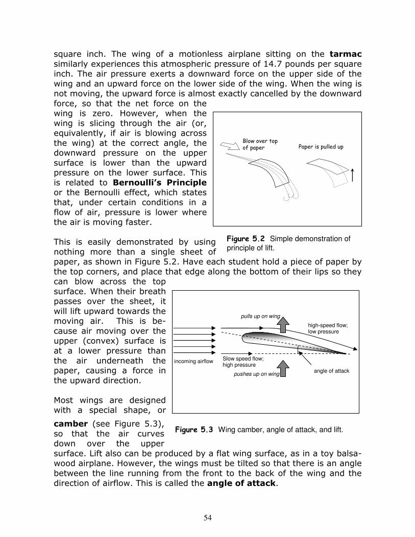
A gas is generally characterized by three quantities: pressure, volume, and temperature. These quantities are related to each other. If you decrease the volume of a quantity of gas by a factor of two without changing its temperature, the pressure will double. If you increase the temperature without changing the volume, the pressure will increase. Does this explain why a Mylar balloon left in a hot car has popped by the time you return? (Mylar does not stretch; hence, the volume cannot increase. Therefore, an increase in the temperature leads to an increase in the pressure until the force is so great that it rips the balloon.) Since air is matter, and matter has weight, air tends to fall toward the ground just as rocks and people do. This confines the air to a region near the surface of the Earth and keeps it from escaping into space. The combination of the weight of the air (which confines it) and the atomic and molecular collisions (related to the temperature) leads to a force per unit of area, and this is just pressure. The air around us exerts a pressure (an atmospheric pressure) of 14.7 pounds on every square inch of our bodies (14.7 pounds per square inch). Fortunately, the pressure on the outside of our body directed inward is balanced by the pressure from inside our body directed outward. Describe what happens when a diver goes under water. Why do your ears “pop” when changing elevation? The next activity demonstrates that air occupies space and exerts pressure. This latter property is not something that is normally obvious. In order to demonstrate air pressure, we have to maintain it on the outside of an object, but remove the balancing pressure exerted from the inside.
Learning Objectives and Skill Development
Characterization of gases: pressure, volume, temperature
Air occupies space (volume)
Air exerts pressure
Properties of Gases and the Air
29
� Tank of water or filled sink
� Clear plastic cup(s)
� Paper towels or tissue paper
� Tin container or two-liter soda bottle (both must have caps that can be
secured tightly)
� Hot plate
� Pot for boiling the water
� Thermal gloves or potholders
Materials
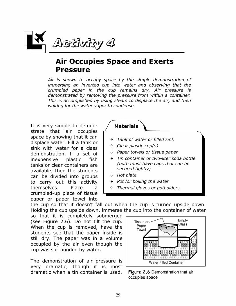
It is very simple to demon-strate that air occupies space by showing that it can displace water. Fill a tank or sink with water for a class demonstration. If a set of inexpensive plastic fish tanks or clear containers are available, then the students can be divided into groups to carry out this activity themselves. Place a crumpled-up piece of tissue paper or paper towel into the cup so that it doesn’t fall out when the cup is turned upside down. Holding the cup upside down, immerse the cup into the container of water so that it is completely submerged (see Figure 2.6). Do not tilt the cup. When the cup is removed, have the students see that the paper inside is still dry. The paper was in a volume occupied by the air even though the cup was surrounded by water. The demonstration of air pressure is very dramatic, though it is most dramatic when a tin container is used.
Tissue or Paper Towel
Empty Glass
Water Filled Container
Figure 2.6 Demonstration that air
occupies space
Air is shown to occupy space by the simple demonstration of
immersing an inverted cup into water and observing that the crumpled paper in the cup remains dry. Air pressure is demonstrated by removing the pressure from within a container.
This is accomplished by using steam to displace the air, and then
waiting for the water vapor to condense.
Air Occupies Space and Exerts Pressure
30
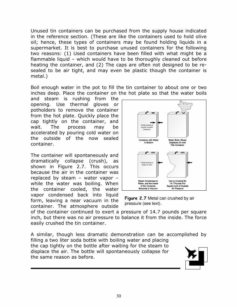
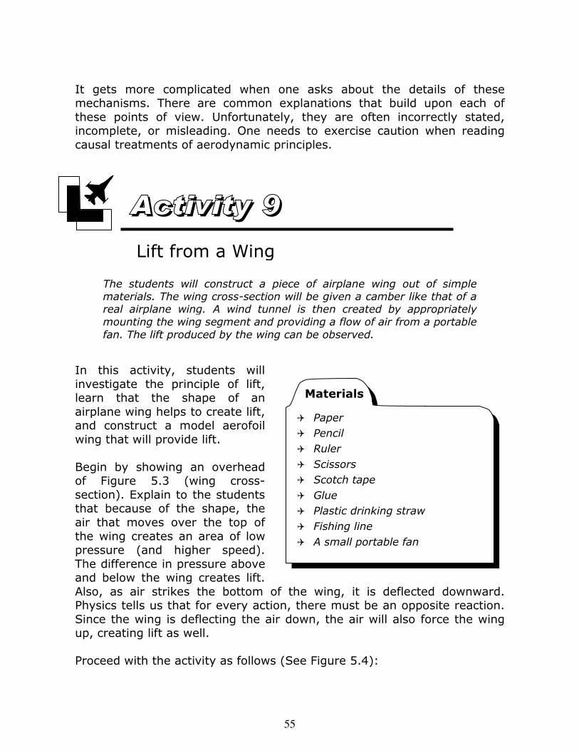
Unused tin containers can be purchased from the supply house indicated in the reference section. (These are like the containers used to hold olive oil; hence, these types of containers may be found holding liquids in a supermarket. It is best to purchase unused containers for the following two reasons: (1) Used containers have been filled with what might be a flammable liquid – which would have to be thoroughly cleaned out before heating the container, and (2) The caps are often not designed to be re-sealed to be air tight, and may even be plastic though the container is metal.) Boil enough water in the pot to fill the tin container to about one or two inches deep. Place the container on the hot plate so that the water boils and steam is rushing from the opening. Use thermal gloves or potholders to remove the container from the hot plate. Quickly place the cap tightly on the container, and wait. The process may be accelerated by pouring cold water on the outside of the now sealed container. The container will spontaneously and dramatically collapse (crush), as shown in Figure 2.7. This occurs because the air in the container was replaced by steam – water vapor – while the water was boiling. When the container cooled, the water vapor condensed back into liquid form, leaving a near vacuum in the container. The atmosphere outside of the container continued to exert a pressure of 14.7 pounds per square inch, but there was no air pressure to balance it from the inside. The force easily crushed the tin container. A similar, though less dramatic demonstration can be accomplished by filling a two liter soda bottle with boiling water and placing the cap tightly on the bottle after waiting for the steam to displace the air. The bottle will spontaneously collapse for the same reason as before.
Figure 2.7 Metal can crushed by air
pressure (see text).
Can is Crushed By 14.7 Pounds Per
Square Inch of Outside Air Pressure
Container with Water in Bottom
Water Boils; Steam Displaces Air and
Fills Container
inside pressure
equals outside
pressure
Steam Condenses to Water, and the Inside
of the Container Becomes a Vacuum
inside pressure
close to zero
Can is Crushed By 14.7 Pounds Per
Square Inch of Outside Air Pressure
Container with Water in Bottom
Water Boils; Steam Displaces Air and
Fills Container
inside pressure
equals outside
pressure
Steam Condenses to Water, and the Inside
of the Container Becomes a Vacuum
inside pressure
close to zero
31
Weight is a concept that everyone takes for granted – adults and children. Weight is actually a force: it is the force exerted on a material object due to the gravitational influence of the Earth. In other words, weight is the
Key Concepts and Subjects
Weight and Density
Buoyancy
Lighter-Than-Air Vehicles
Atmosphere
Graphs
Respiratory and Circulatory
Systems
Sections
3a Weight and Density
3b Buoyancy and Lighter-Than-
Air Vehicles
3c Earth’s Atmosphere, Changes
with Altitude, and Human
Respiratory and Circulatory
Systems
Activities
5 Air Has Weight
6 Construction of a Hot-Air Balloon
In this lesson, students examine the concept of buoyancy, and the characteristics of an object that allow it to remain suspended in the air or in the ocean without falling. The teacher will begin by developing the concepts of weight and density. (We will take density to measure weight per unit volume.) These concepts are applied to lighter-than-air and submersible vehicles in the second section, and followed in the third section with an examination of the atmosphere of the Earth and the changes in the atmosphere with increasing altitude. Life science aspects are considered with a treatment of respiration and blood flow, and the effects of high altitudes and ocean depths on human physiology and psychology.
Overview
Weight and Density
Learning Objectives and Skill Development
Weight as the force exerted on an object by gravity
Density as weight per unit volume
Air has weight
32
� Yard stick, or any thin, light stick or rod two-to-three feet long
� Light string or thread
� Two identical balloons
� Tape
� Scissor or sharp object
Materials
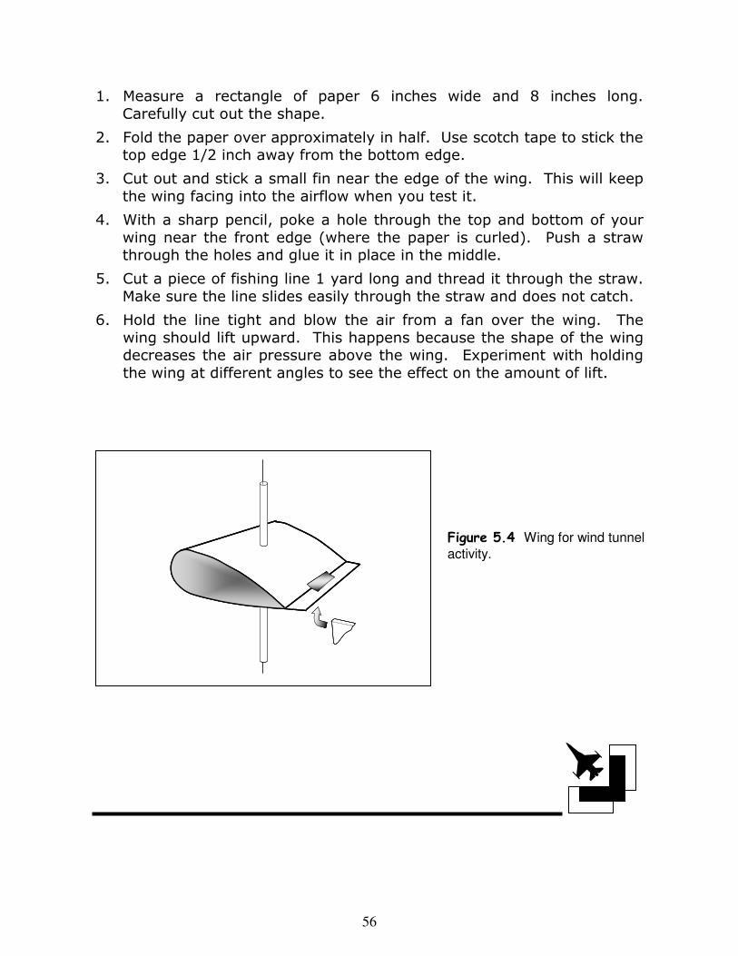
force on an object due to gravity, produced by the Earth. Since air itself is composed of matter – mostly nitrogen and oxygen atoms – it too has weight. It is the weight of the atmosphere that is responsible for the air not leaking into space. In the following activity, the weight of air is demonstrated.
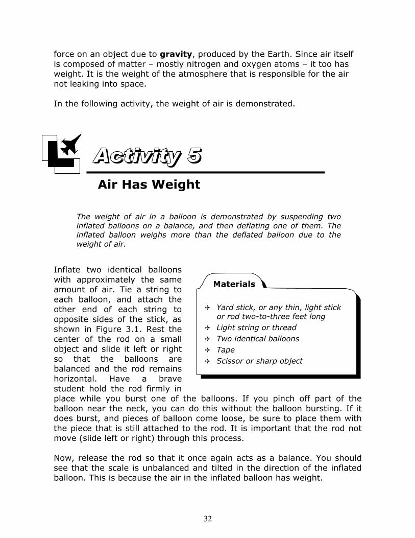
Inflate two identical balloons with approximately the same amount of air. Tie a string to each balloon, and attach the other end of each string to opposite sides of the stick, as shown in Figure 3.1. Rest the center of the rod on a small object and slide it left or right so that the balloons are balanced and the rod remains horizontal. Have a brave student hold the rod firmly in place while you burst one of the balloons. If you pinch off part of the balloon near the neck, you can do this without the balloon bursting. If it does burst, and pieces of balloon come loose, be sure to place them with the piece that is still attached to the rod. It is important that the rod not move (slide left or right) through this process. Now, release the rod so that it once again acts as a balance. You should see that the scale is unbalanced and tilted in the direction of the inflated balloon. This is because the air in the inflated balloon has weight.
Air Has Weight
The weight of air in a balloon is demonstrated by suspending two
inflated balloons on a balance, and then deflating one of them. The inflated balloon weighs more than the deflated balloon due to the
weight of air.
33
An alternative procedure in-volves balancing two un-inflated balloons. One of them is re-moved, inflated, and re-attached at the same spot.
Sometimes an object is heavy because it is big. But even small objects can be heavy. Some objects simply pack more matter into a given volume than other objects. These objects have a high density. Density is a measure of the amount of matter per unit of volume. For our purposes, we can take it to represent weight per unit volume, calculated simply by taking the weight of the object and dividing it by the volume of the object. Some examples of material densities are given below in Table 3.1: Substance Density (grams/cubic cm) Density (pounds/cubic foot) Wood (elm) 0.6 37 Olive oil 0.9 56 Water 1.0 62 Aluminum 2.7 169 Feldspars (sand) 2.7 169 Earth (average) 5.5 343 Steel 7.9 493 Iron 8.0 499 Copper 9.0 562 Lead 11.3 705 Gold 19.3 1205 Table 3.1 Densities of selected materials Density determines whether an object falls, rises, or remains suspended in either air or water. If an object is less dense than water, it rises and
Figure 3.1 Demonstrating that air has weight.
34
floats. If it is denser, it sinks. If it has the same density, it remains suspended at some depth, like a fish or a submarine. The same is true of objects that float in the air. For a balloon to remain suspended in the air, the combination of the balloon material and the gas it contains must have the same average density as the air it displaces.
Consider an imaginary balloon that has no weight at all when it’s not in-flated (a very, very light material). If it is inflated it with air – the same stuff that surrounds it – it would neither move up nor down. It would simply float in place. But, what keeps it from falling under the influ-ence of gravity due to the weight of the air in the balloon? Answer: The same force that keeps any volume of air in place even when not confined by our imagi-nary balloon. It is the principle of buoyancy. Buoyancy is the net upward force that the air exerts on any object it surrounds. Figure 3.2 shows an object floating in the air. The air pressure above the object is pushing down. The air pressure below the object is pushing up with almost
G
Force due to air
pushing up on bottom
Force due to air
pushing down on top
Force of gravity
pulling down (weight of air)
Air (surrounded
by air)
+
=
Force due to air
pushing up on bottom
Force due to air
pushing down on top
Buoyancy Force
=Force due to air
pushing up on bottom
Force due to air
pushing down on top
G Weight of air
+
G
Force due to air
pushing up on bottom
Force due to air
pushing down on top
Force of gravity
pulling down (weight of air)
Air (surrounded
by air)
G
Force due to air
pushing up on bottom
Force due to air
pushing down on top
Force of gravity
pulling down (weight of air)
Air (surrounded
by air)
+
=
Force due to air
pushing up on bottom
Force due to air
pushing down on top
Buoyancy Force
=Force due to air
pushing up on bottom
Force due to air
pushing down on top
G Weight of air
+
Figure 3.2 The upward force due to buoyancy versus the
downward weight force (due to gravity).
Buoyancy and Lighter-Than-Air
Vehicles
Learning Objectives and Skill Development
Principle of balancing forces
Fluid displacement and the buoyancy force
Principles of helium and hot-air balloons
Construction of a hot air balloon
Air
G
Force of air pushing up
from bottom
Force of air pushing down from top
Weight of balloon itself
GWeight of air in balloon
Net Force (Down)
Heliu
m
G
Force of air pushing up
from bottom
Force of air pushing down from top
Weight of balloon itself
G Weight of heliumin balloonNet Force (Up)
Air
G
Force of air pushing up
from bottom
Force of air pushing down from top
Weight of balloon itself
GWeight of air in balloon
Net Force (Down)
Heliu
m
G
Force of air pushing up
from bottom
Force of air pushing down from top
Weight of balloon itself
G Weight of heliumin balloonNet Force (Up)
35
� Plastic bags from a dry cleaner
� Small paper clips
� Cellophane tape
� Blow dryer
Materials
– but not quite exactly – the same strength. Air pressure diminishes as one goes higher and higher. Hence, the upward pressure on the lower surface is always slightly greater than the downward pressure on the upper surface. The difference in the two forces is just (exactly) enough to support the volume of air. But, now imagine that we replace the air in our imaginary balloon with a gas that is lighter than the air it displaces. Now, the net upward force will exceed the weight of the gas in our balloon, and the balloon will rise. This is what happens when a balloon is filled with either a lighter gas, such as helium, or heated air, which is also less dense than cooler air. Of course, the material of a real balloon has weight. Hence, the gas has to be sufficiently light so that both the balloon material and the contained gas can be supported. This is also the principle by which boats float or submarines can remain suspended under water.
Proceed according to the following steps: 1. Seal up any openings or holes in the top of the plastic bag using the cellophane tape. Try to use as little of the tape as possible, as we want to avoid adding too much extra weight to the bag. 2. At the bottom of the bag, attach several of the paper clips. (The weight will keep the open side of the bag pointed down.) Try to space them out evenly so that the weight is distributed. The actual number of paper clips that should be added needs
Construction of a Hot-Air Balloon
A simple hot-air balloon is constructed and flown. This demon-strates both the principle of buoyancy and the fact that heated air
has a reduced density.
36
to be determined by trial and error. It is going to depend on the bag you are using. 3. Turn on the blow dryer and aim it up. Spread the opening at the bottom of the bag so that it can capture the hot air rising from the blow dryer. Make sure to support the top end of the bag while you are heating the air. It helps to have a second person to assist at this point. They need to keep the bottom of the bag open and out of contact with the hair dryer to keep the plastic from melting. 4. Once the bag has been filled with hot air, check it’s buoyancy by letting go of it. If it starts to fall, continue heating the air. If it rises, stand back and watch it float. 5. If the bag tends to fall over sideways letting the air spill out, add a few more paper clips to the bottom to weigh it down a bit more. This is where some experimentation will be needed.
The Earth’s atmosphere is composed primarily of the gases nitrogen and oxygen. The air is about 78% nitrogen, 21% oxygen, and 1% other gases, largely argon, water vapor, and carbon dioxide. Of course, oxygen is required for us to breathe, and to support burning.
Earth’s Atmosphere, Changes with
Altitude, and Human Respiratory
and Circulatory Systems
Learning Objectives and Skill Development
Composition of the atmosphere
Pressure and temperature changes with altitude
Atmospheres of other planets
Human respiratory and circulatory systems, and the effects of high altitudes and underwater depths
Graphs
37
Near the surface of the Earth, the air is dense and exerts a pressure of 14.7 pounds per square inch. As one goes higher and higher, the density and pressure of the air diminish. This is why aircraft (including balloons and blimps) can only go so high, and why special breathing devices are necessary at high altitudes. Most people would require oxygen masks when climbing Mount Everest, which is about 29,000 feet high (over five miles). At an altitude of 29,000 feet, the air pressure drops to 4.6 pounds per square inch. The temperature of the air also decreases significantly. The pilot of an airliner is well acquainted with atmospheric characteristics at high altitudes since this information is critical to maintaining the comfort and safety of the flight. Captain Joseph D’Angelo, a Boeing 737 pilot for Continental Airlines, describes some of these issues in the quote below (text in curly brackets added by the authors):
“The pilot of any aircraft must be constantly aware of conditions outside the aircraft. Pilots typically refer to temperature in degree Celsius, altitude in feet above ground level or above sea level, and speed in knots. One knot is one nautical mile per hour, and this is about 1.15 (statute, or ordinary) miles per hour. In a typical flight aboard a Boeing 737, we fly at an altitude of about 35,000 feet. I have seen outside temperature readings as low as 59 degrees Celsius below zero! {This is 74 degrees below zero Fahrenheit!} The air outside the aircraft can be moving at speeds of 160 knots when we are flying in the jet stream. {This is over 180 miles per hour! Hurricane-force winds at ground level are defined by wind speeds of at least 75 miles per hour.} The 737 cruises at an airspeed of about 460 knots {about 530 miles per hour}. So, if we are flying in 160 knot winds, our ground speed – the speed relative to the ground – can be as low as 460 minus 160, or 300 knots {345 miles per hour} when flying into the wind, or as high as 460 plus 160, or 620 knots {about 715 miles per hour} when flying with the wind. The air pressure outside the aircraft is about 3 pounds per square inch at an altitude of 35,000 feet.”
Captain D’Angelo continued by describing issues relating to the structure and integrity of the aircraft as they relate to conditions outside of the vehicle:
38
“All types of aircraft experience stresses due to the air flowing over its surfaces. Different types of aircraft have differing levels of tolerance to these stresses. Airplanes designed for acrobatics and fighter jets are designed to tolerate high stresses. Most other aircraft are not designed to withstand the high stresses that might be produced by abrupt changes in direction, especially pitch {up and down motion}. Another source of undesirable forces on an aircraft is called wake turbulence. The wake turbulence produced by the aircraft that landed just in front of you can remain for some time. Therefore, measures are taken by pilots to avoid running into wake turbulence when landing. By flying slightly above the glide path of the preceding aircraft, the pilot can avoid running into wake turbulence. Another atmospheric concern is icing on the wings. The wings are designed with a special cross-sectional shape to provide lift. {This is described later in this document} If ice forms on the wings, the effective shape of the wing surface is changed, and lift can be significantly diminished. Conditions favorable to icing must be monitored very closely by pilots of both large and small aircraft.”
Captain D’Angelo commented on the environment that must be maintained in the cabin of the aircraft.
“As the aircraft gains altitude, the outside air pressure decreases. Airliners, like the 737, must maintain a pressure in the aircraft higher than that outside while flying at high altitudes. As an airliner ascends to cruising altitude, the cabin air pressure is permitted to diminish, but never drops below the air pressure at 8,000 feet above sea level, corresponding to about 11 pounds per square inch. If the cabin lost air pressure at, say, 35,000 feet, the passengers and crew would have only about 30-60 seconds to don oxygen masks before losing consciousness. Even flying at 12,000-18,000 feet can lead to conditions of impaired judgment since the brain is not getting enough oxygen, and may lead to unconsciousness within 20-30 minutes.”
Captain D’Angelo points out that even though aircraft operate in a hostile environment, they are designed to work under those conditions. This message should be conveyed to the students.
39
These conditions also affect mountain climbers. Quoting from “Into Thin Air,” by Jon Krakauer (Anchor Books, 1997, pp 3-4)
“Straddling the top of the world, one foot in China and the other in Nepal, I cleared the ice from my oxygen mask, hunched a shoulder against the wind, and stared absently down at the vastness of Tibet. I understood on some dim, detached level that the sweep of earth beneath my feet was a spectacular sight. I’d been fantasizing about this moment, and the release of emotion that would accompany it, for many months. But, now that I was finally here, actually standing on the summit of Mount Everest, I just couldn’t summon the energy to care.”
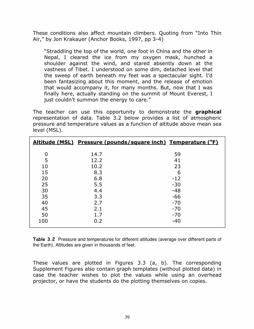
The teacher can use this opportunity to demonstrate the graphical representation of data. Table 3.2 below provides a list of atmospheric pressure and temperature values as a function of altitude above mean sea level (MSL). Altitude (MSL) Pressure (pounds/square inch) Temperature (oF) 0 14.7 59 5 12.2 41 10 10.2 23 15 8.3 6 20 6.8 -12 25 5.5 -30 30 4.4 -48 35 3.3 -66 40 2.7 -70 45 2.1 -70 50 1.7 -70 100 0.2 -40
Table 3.2 Pressure and temperatures for different altitudes (average over different parts of
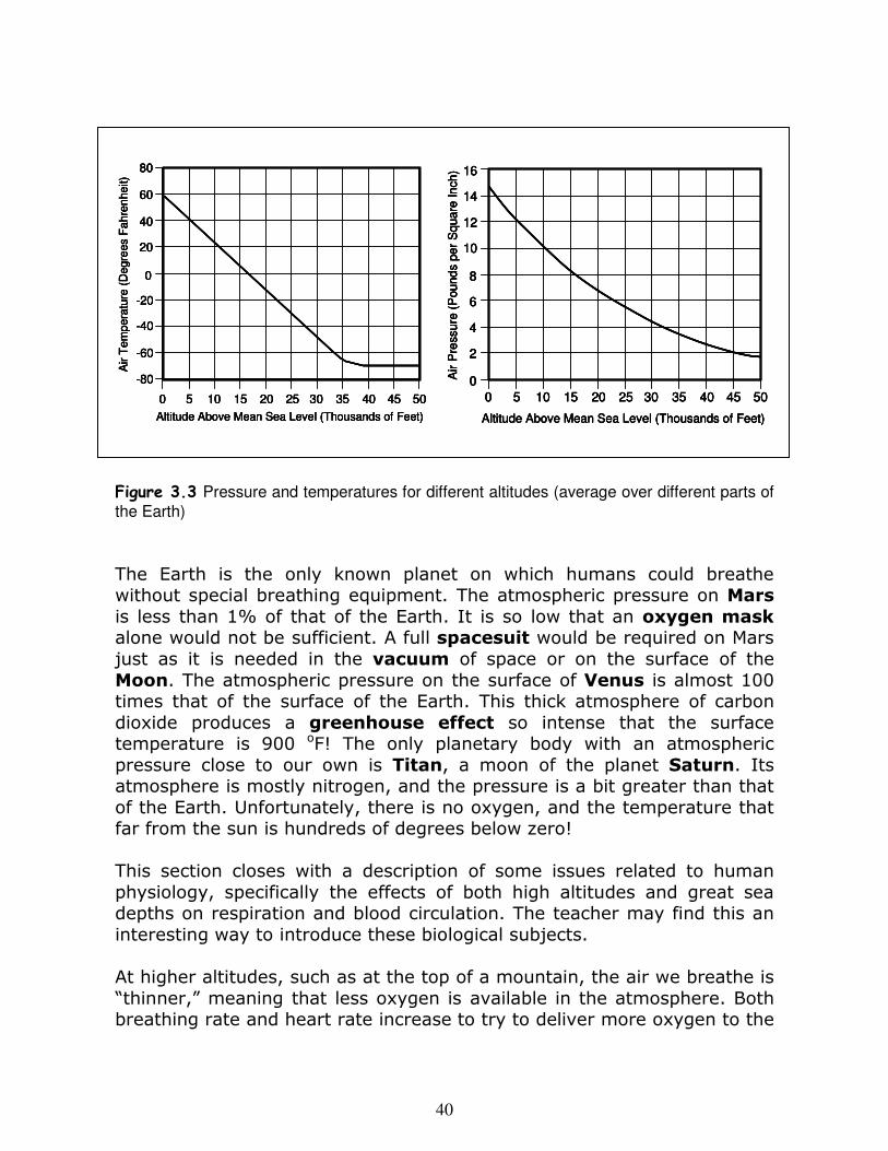
the Earth). Altitudes are given in thousands of feet. These values are plotted in Figures 3.3 (a, b). The corresponding Supplement Figures also contain graph templates (without plotted data) in case the teacher wishes to plot the values while using an overhead projector, or have the students do the plotting themselves on copies.
40
Figure 3.3 Pressure and temperatures for different altitudes (average over different parts of
the Earth)
The Earth is the only known planet on which humans could breathe without special breathing equipment. The atmospheric pressure on Mars is less than 1% of that of the Earth. It is so low that an oxygen mask alone would not be sufficient. A full spacesuit would be required on Mars just as it is needed in the vacuum of space or on the surface of the Moon. The atmospheric pressure on the surface of Venus is almost 100 times that of the surface of the Earth. This thick atmosphere of carbon dioxide produces a greenhouse effect so intense that the surface temperature is 900 oF! The only planetary body with an atmospheric pressure close to our own is Titan, a moon of the planet Saturn. Its atmosphere is mostly nitrogen, and the pressure is a bit greater than that of the Earth. Unfortunately, there is no oxygen, and the temperature that far from the sun is hundreds of degrees below zero! This section closes with a description of some issues related to human physiology, specifically the effects of both high altitudes and great sea depths on respiration and blood circulation. The teacher may find this an interesting way to introduce these biological subjects. At higher altitudes, such as at the top of a mountain, the air we breathe is “thinner,” meaning that less oxygen is available in the atmosphere. Both breathing rate and heart rate increase to try to deliver more oxygen to the
0
0 5 10 15 20 25 30 35 40 45 50
Air
Te
mp
era
ture
(D
egre
es F
ah
ren
he
it)
Altitude Above Mean Sea Level (Thousands of Feet)
-20
20
-40
-60
-80
40
60
80
0
0 5 10 15 20 25 30 35 40 45 50
Air
Te
mp
era
ture
(D
egre
es F
ah
ren
he
it)
Altitude Above Mean Sea Level (Thousands of Feet)
-20
20
-40
-60
-80
40
60
80
0
2
4
6
8
10
12
14
16
0 5 10 15 20 25 30 35 40 45 50
Air P
ressure
(P
ou
nd
s p
er
Sq
ua
re In
ch
)
Altitude Above Mean Sea Level (Thousands of Feet)
0
2
4
6
8
10
12
14
16
0 5 10 15 20 25 30 35 40 45 50
Air P
ressure
(P
ou
nd
s p
er
Sq
ua
re In
ch
)
Altitude Above Mean Sea Level (Thousands of Feet)
0
0 5 10 15 20 25 30 35 40 45 50
Air
Te
mp
era
ture
(D
egre
es F
ah
ren
he
it)
Altitude Above Mean Sea Level (Thousands of Feet)
-20
20
-40
-60
-80
40
60
80
0
0 5 10 15 20 25 30 35 40 45 50
Air
Te
mp
era
ture
(D
egre
es F
ah
ren
he
it)
Altitude Above Mean Sea Level (Thousands of Feet)
-20
20
-40
-60
-80
40
60
80
0
2
4
6
8
10
12
14
16
0 5 10 15 20 25 30 35 40 45 50
Air P
ressure
(P
ou
nd
s p
er
Sq
ua
re In
ch
)
Altitude Above Mean Sea Level (Thousands of Feet)
0
2
4
6
8
10
12
14
16
0 5 10 15 20 25 30 35 40 45 50
Air P
ressure
(P
ou
nd
s p
er
Sq
ua
re In
ch
)
Altitude Above Mean Sea Level (Thousands of Feet)
41
different tissues in the body. If the air becomes too “thin” an insufficient amount of oxygen will be delivered through the body, a condition known as hypoxia. Some symptoms of oxygen insufficiency are headache, fatigue, dizziness, nausea, vomiting, insomnia, and swelling of the face, hands, and feet. At very high altitudes, the lower barometric pressure causes capillaries in the brain, lungs and extremities to constrict. Body fluid can then leak into the brain, known as cerebral edema, or into the lungs, known as pulmonary edema. Both of these conditions can be life-threatening. At lower altitudes, such as the bottom of the ocean, the water pressure exerted on your body is much larger than the air pressure at sea level. The deeper you go, the greater the force per unit area. This increased pressure allows more oxygen and nitrogen, the two most abundant gases in the atmosphere, to dissolve into the blood. At about 100 feet below sea level, the pressure will cause enough nitrogen to dissolve in the blood to become harmful. Nitrogen narcosis can results from too much nitrogen being forced into the blood stream. Divers can become dizzy, impairing their ability to make even simple mental decisions. Nitrogen, unlike oxygen is a biologically inert gas, meaning that it is not metabolized by the body. Since divers can not exhale the nitrogen as they could at surface levels, nitrogen is deposited in the tissues until the diver begins the return to the surface. As he or she comes up, the water pressure decreases and the nitrogen diffuses out of the tissues into the blood stream. If the diver surfaces too quickly, nitrogen bubbles can form, obstructing arteries, veins, nerves, and lymphatic vessels. Pain is often the only symptom, often referred to as “the bends.” More severe symptoms can range from severe itching and skin rashes to paralysis, brain damage, heart attacks, or even death.
42
Key Concepts and Subjects
Characterizing Motion
Forces and Motion
Friction and Drag Forces
Law of Action and Reaction
Thrust and Propulsion
g-Forces
Physiology of Motion and
Weightlessness
Sections
4a Position, Speed, and
Acceleration; Forces and
Motion; Friction and Drag
Forces
4b Law of Action and
Reaction; Thrust and the
Air Engine
4c People in Motion; Forces
on the Human Body
Activities
7 Construction of a
Parachute and
Measurement of Speed 8 Construction of an Air
Engine
This lesson deals with the forces that propel an aircraft, and, more fundamentally, with the characterization of motion and the relationship between force and motion. The quantities that characterize motion are position, speed, and acceleration. Students learned in the previous lesson that an object can float in the air if we balance the weight and buoyant forces. In the first section, students will learn that an unbalanced force will always produce an acceleration (leading to a change in speed). If there is no change in speed, then there is no unbalanced force. When present, frictional or drag forces always oppose the motion of an object. A parachute uses this principle to bring a skydiver to the ground slowly. Students will construct a parachute and measure its average speed. Aircraft engineers can use the principle of action and reaction to provide the force needed to accelerate an object, and then to maintain its speed in the presence of drag forces. This mode of propulsion is described and demonstrated by the construction an air engine in the second section. Finally, the effects of acceleration and weightlessness on the human body are considered in the last section.
Overview
Position, Speed, and Acceleration;
Forces and Motion; Friction and
Drag Forces
43
The position of an object along a line can be characterized by its distance from some reference point. This could be the number of inches between the starting point of a moving object and its location at a later time. Speed (or velocity) is a measure of how quickly a given distance is covered by a moving object. (Speed = distance/time) If an object travels 200 inches in 4 seconds, then its average speed is 200 divided by 4, or 50 inches per second. If a car travels 90 miles in two hours, then it is traveling at a speed of 45 miles per hour. The rate at which an object gains speed is called acceleration. An applied force – a push or a pull – is required to start an object moving. In other words, a force produces a change in speed. The quantification of this statement is Newton’s Second Law of Motion. It relates the force applied to an object and the rate at which it accelerates (gains speed). In the absence of forces (or, at least in the absence of a net, unbalanced force), an object will continue to move with the same speed. This is Newton’s First Law of Motion: An object at rest will remain at rest or an object in motion will remain in uniform motion unless acted upon by a net (that is, unbalanced) force. This property is called inertia. In the absence of friction or other opposing forces and the absence of an applied force, a moving object will continue to move with the same speed. If our moving object encounters an opposing force, such as friction, then the applied force must be maintained or the object will slow down and stop moving. This is the case with all flying vehicles that operate within the Earth’s atmosphere since all encounter air friction (also called drag).
Learning Objectives and Skill Development
Definition of position, speed, and acceleration
Laws of motion that relate force and motion
Frictional and drag forces
Construction of a parachute
Measurement and calculation of average speed
44
� Plastic Shopping Bag
� Scissors
� Pencil/Marker
� Wedge Template, Supplement Fig. 4.1
� Ruler
� Weight or small toy for payload
(something light, about the size and weight of a toy plastic soldier)
� Cellophane tape
Materials
Follow the instructions below: 1. Start by cutting the plastic shopping bag in half, so you can make two parachutes out of each plastic bag. Have the students find the ap-proximate center of the plastic, place the corner of the wedge template at the center, and trace the curved portion with the marker (see Figure 4.1 and use Supplement Figure 4.1 as the template). Turn the template a quarter turn, and continue to trace. Repeat this until the circle is complete, taking care to keep the corner of the template at the center. (Note: This is just a simple way for the students to draw a circle of diameter 13 ½ inches.) Now the students can cut out the parachute. 2. Next, cut three pieces of string about 18-20 inches long. We are going to want to attach each string to two points on the outside of our circle, directly opposite each other. To do this, fold the parachute in half, and tape the ends of one of the strings to the two corners. This gives us our first attachment point. Reopen the parachute. Fold it in half again, this time so that the corners are a little more than six inches from where the first string is attached. Attach the string in the same fashion as before.
Construction of a Parachute and Measurement of Speed
The students will construct parachutes out of simple materials, and demonstrate the concept of drag by releasing them. This
activity can be expanded by having students measure distance and time of fall. They can then use this information to calculate
the speed at which the parachute descends.
45
� Stop watch
� Yardstick
Materials
Repeat this for the final string. Our goal is to have the strings at-tached to six evenly spaced points around the circle. 3. Bring the centers of the strings together so that the edges of the parachutes are even. Wrap the strings around the weight or toy, and then tape the string down to prevent the weight from falling out of the parachute. 4. Close the parachute, and wrap the strings around it loosely. The parachute is now packed and ready for flight. Toss it into the air and watch it float back down to the ground. This activity can be expanded by asking the students to measure the average speed of the falling parachute:
1. Measure a point several feet off the floor for use as the starting point from where the parachutes will be dropped. This spot should be high enough to allow the parachute to open fully. A stairwell or stage may be useful for this. 2. Place one student in charge of the parachute and another a stopwatch. The second student will measure the amount of time it takes for the parachute to travel from the release point to the floor. We can calculate the average speed of the parachute by this equation: Speed = (Distance fallen) / (time of fall) If desired, the students can try making parachutes of different sizes or out of different materials and see if there is a difference in the average speed of the parachute. Larger parachutes should travel slower than smaller parachutes with the same weight.
Figure 4.1 Picture of wedge template. Use
the full-sized version in Supplement Figure 4.1
46
Many people have heard the statement that for every action there is an equal and opposite reaction. This is Newton’s Third Law of Motion, and is sometimes referred to the Law of Action and Reaction. Stated another way, if object number one exerts a force on object number two, then object number two exerts the same force back on object number one, but in the opposite direction. This is why if you throw something heavy in a forward direction, you experience a force in a backward direction. The teachers should have two students sit on two chairs with wheels. Facing each other and with the soles of their shoes together, have one student try to push the other student away. Notice that they both move apart. Heavier-than-air vehicles, like airplanes, jets and rockets, all use this principle to propel themselves. They simply take a gas and propel it rapidly in some direction, with the net result that they are propelled in the opposite direction. The force produced by the rapid ejection of a gas is called thrust. An airplane uses a propeller – a fan – driven by an internal combustion engine (like that in a car) to move the air. Modern jet engines, called turbofan jet engines, use both heated exhaust gases and air blown back by fans contained within the engine housings. Rockets burn a fuel by mixing it with an oxidizer (often, super-cooled liquefied oxygen). These burned gases are ejected from the rocket engine at extremely high velocities. (These engines are described in more detail in a subsequent lesson.) Note that the principle of thrust relies purely on the Law of Action and Reaction. It does not require that the exhaust gases push against anything, contrary to early concerns expressed by non-scientists that rockets couldn’t work in space because there was no air for the exhaust gases to push against!
Law of Action and Reaction;
Thrust and the Air Engine
Learning Objectives and Skill Development
Principle of action and reaction
Concept of thrust
Construction of a reaction (air) engine
Measurements and calculations of average speed
Graphing of data
47
� Balloon (cylindrical, but not too thin)
� Plastic straw – cut into two pieces; 5” and 3”
� Clothes pin
� Rubber bands (small)
� Graph paper and straight edge
� Scissors
� Construction paper
� Colored pencils or crayons
� Calculators, optional
Materials for Each Student
� Fishing line
� Masking tape (wide)
� Tape measure or trundle wheel
� Protractor
� Scotch tape
� Stop watches, or watch with
second hand
Materials
for Class
Demonstrate the effect by blowing up a balloon and releasing it. Explain that the balloon air engine used in this activity makes use of the fact that the air pressure inside the balloon is greater than that outside the balloon. This pressure difference is produced by the tendency of the balloon to return to its original (un-blown-up) size, thereby squeezing the air inside. The air is ejected when the balloon is open until the inside and outside pressures equalize. In the next activity, students construct a reaction engine. This activity is described in a form that is more substantial, and therefore more time consuming, than earlier activities. This activity can be reduced to a demonstration if time constraints prevent the full treatment.
Construction of an Air Engine
Students will use balloons to demonstrate the principle of generating thrust, as in aircraft engines. They will measure the speeds of their balloon-craft, and consider the effect of degree of inflation and other factors on the distance
traveled.
48
1. The teacher should fasten a fishing line horizontally across the room, with a length of about 30 feet. One end should be loosely fastened since the line will be threaded into the straw (with balloon attached). 2. The teacher will demonstrate the construction of a simple, basic balloon engine. There are two options at this point. One can insert the 3 inch section of straw into the balloon neck and fasten the balloon neck to the straw using a rubber band. The presence of the straw reduces the rate at which air (exhaust gas) is released. Alternatively, the straw can be omitted. Inflate the balloon with several puffs of air and either pinch the end closed with a clothes pin (if no straw is used) or ask a student to hold his/her finger over the straw (if a straw is used). Use the wide masking tape to secure the other straw along the long direction of the inflated balloon. The straw will function as a guide. Now thread the loose end of the launch line (fishing line) through the straw and launch the air engine by releasing the end (removing either clothes pin or finger). (See Figure 4.2) 3. After reminding students to work carefully in the Lab setting to prevent injuries, allow them to create their own air engine following the teacher’s model from step 2. Each student should be provided with the materials needed to construct an air engine. NOTE: Each student should have his or her own balloon, so only one person’s mouth touches any balloon. The teacher may wish to group students into teams. 4. Have students make predictions about the motion of the air engine. Ask them to consider the effects of changing the number of puffs of air, the angle of the string, and the weight of the air engine. 5. Launch several students’ balloons on the horizontal fishing line (see Figure 4.2). Have a student fill the balloon with different amount of air, measured by number of puffs. Determine how far the balloon goes as a function of number of puffs by making a measurement with the tape
Figure 4.2 The air engine
49
measure. Make a table of these numbers on the blackboard. Then do the same for different angles relative to horizontal, measured with a protractor. One can also attach various weights to the straw or balloon to simulate a payload carried by a rocket. Extra clothespins can be used as weights. Involve all students in one activity or another (starting the balloon by removing the clothes pin or finger, making a meas-urement, etc.). 6. Students should individually graph the distance the balloon rockets traveled depending upon the numbers of puffs taken and the angle of flight. These graphs can then be used for follow-up discussion with the class. Graph paper can be copied from the template of the Supplement to Figure 4.3 (shown here in reduced form). 7. Using the formula Speed = Distance/Time, students will compute speeds and complete a graph to record this information. 8. Have the students return to their own desks (we are done with the teams). Each student should embellish their balloon rocket using construction paper and tape (nose cone, fins, etc.) and markers. Note: since this step requires an inflated balloon, it is best to omit the straw from the neck of the balloon so that a clothes pin can be used to hold the air. 9. Give each student a chance to test his or her rocket on the fishing line.
Figure 4.3 Reduced version of graph
template (Use Supplement version)
50
Weightlessness can have devastating effects on the physiology of the human body. For astronauts orbiting the Earth, the vestibular organ in the inner ear, which is responsible for balance and orientation, is not able to function, and disorientation and motion sickness occur. Motion sickness is usually accompanied by headache, impaired concentration, loss of appetite, and vomiting, usually lasting for no more than three days in space. Muscles also begin to atrophy and blood and other fluids move toward the head and away from the lower parts of the body, making it difficult to walk once returning to earth. Thirst and frequent urination occur from the excessive fluid buildup in the upper body area, also causing an appearance characterized by a puffy face and skinny legs. The heart also looses mass and works less hard since less effort is needed in a gravity-free environment. A potentially serious side effect of weightlessness is the loss of bone mass from the lack of stress on the bones to form osteoblasts, or new bone cells. Calcium is excreted from the bones since it is not being used in the formation of osteoblasts and osteoporosis can occur along with the development of kidney stones. Increase in height and back pain can result from the lengthening and straightening of the spine caused by the lack of stress on the bones. Acceleration also can cause similar stresses on the body. Blackouts, loss of consciousness with accompanying seizures, convulsions, amnesia and confusion, cardiac dysrhythmias (tachycardia - rapid heartbeat and bradycardia - slow heartbeat), heart blocks, and a stress cardiomyopathy (damage to heart muscles causing inadequate pumping) can all result from acceleration. This can be accompanied by an increase in cardiac rate, vasoconstriction and venoconstriction, and an increase in cardiac contractile forces. Musculoskeletal problems most frequently encountered are back, neck, and limb problems.
People in Motion; Forces on
the Human Body
Learning Objectives and Skill Development
Forces on the human body while accelerating
Rocket travel; car accidents
Effects of weightlessness on the human body
51
Pulmonary functioning is also affected by acceleration forces greater than the force of gravity on Earth. Some of these include: altered ventilation/perfusion ratios resulting in hypoxemia (insufficient oxygen in the blood), airway closure, pulmonary edema (fluid accumulation and swelling in lungs), and atelectasis (collapse of alveoli in the dependent lung caused by absorption of the alveolar gas). Atelectiasis is associated with symptoms of coughing, chest pain, and dyspnea (difficulty breathing).
52
In order for an aircraft to maintain straight and level flight, the downward force of gravity – the weight of the airplane – must be balanced by an
Key Concepts and Subjects
Parts of an Airplane
Forces on an Aircraft
Generation of Lift
Aircraft Control
Design and Construction
Propellers, Rotors, and
Helicopters
Sections
5a Forces on an Aircraft
5b Wings and Lift
5c Aircraft Parts and Control
5d Gliders
5e Propellers, Rotors, and
Helicopters
Activities
9 Lift from a Wing 10 Construction of Paper
Airplanes; Balsa Gliders
11 Rotor Construction; Motion and Analysis
Overview
This lesson examines the forces on an airplane and how the various components and systems are used together to achieve flight and maintain control. An aircraft experiences the forces of lift, weight (gravity), thrust, and drag (friction). The manner in which these act on the aircraft is described in the first section. All of these forces except lift have been treated in previous lessons. The fourth force on an aircraft – lift – is examined in the second section. In order to maintain control, aerodynamic surfaces that constitute components of the aircraft must be moved in certain ways. The parts of an airplane and how they control the aircraft are treated in the third section. The flight of un-powered aircraft – gliders – is introduced in the fourth section, and students are taught how to construct paper gliders. The specific use of propellers and rotors to produce thrust is addressed in the last section, and demonstrated with the construction of a working rotor.
Forces on an Aircraft
Learning Objectives and Skill Development
Forces of Lift, Weight, Thrust, and Drag
53
equal upward force, called lift. The lift force is produced by the wings of an airplane, and the wings must be designed to support the weight of the airplane. The air exerts an upward force on the wings and the wings exert an upward force on the rest of the airplane. Essentially, the air holds up the wings and the wings hold up the airplane. The four forces that act on an airplane in flight are shown in Figure 5.1.
The basic principle leading to the production of lift on the wings is really very simple since it follows directly from the Law of Action and Reaction. The wing of an airplane is designed and angled so that the air encounter-ing the wing is deflected downward by the wing. By the Law of Action and Reaction, this leads to a force in the upward direction on the wing. There is another way of looking at the effect which is totally equivalent to the Action/Reaction approach. The air that surrounds us exerts a considerable pressure – a force per unit area of 14.7 pounds for every
Lift
Weight
Thrust
Drag
Figure 5.1 Four forces on an airplane.
Wings and Lift
Learning Objectives and Skill Development Wings and aircraft lift: How they work Applications of the law of action and reaction
Bernoulli’s principle
54
square inch. The wing of a motionless airplane sitting on the tarmac similarly experiences this atmospheric pressure of 14.7 pounds per square inch. The air pressure exerts a downward force on the upper side of the wing and an upward force on the lower side of the wing. When the wing is not moving, the upward force is almost exactly cancelled by the downward force, so that the net force on the wing is zero. However, when the wing is slicing through the air (or, equivalently, if air is blowing across the wing) at the correct angle, the downward pressure on the upper surface is lower than the upward pressure on the lower surface. This is related to Bernoulli’s Principle or the Bernoulli effect, which states that, under certain conditions in a flow of air, pressure is lower where the air is moving faster. This is easily demonstrated by using nothing more than a single sheet of paper, as shown in Figure 5.2. Have each student hold a piece of paper by the top corners, and place that edge along the bottom of their lips so they can blow across the top surface. When their breath passes over the sheet, it will lift upward towards the moving air. This is be-cause air moving over the upper (convex) surface is at a lower pressure than the air underneath the paper, causing a force in the upward direction. Most wings are designed with a special shape, or
camber (see Figure 5.3), so that the air curves down over the upper surface. Lift also can be produced by a flat wing surface, as in a toy balsa-wood airplane. However, the wings must be tilted so that there is an angle between the line running from the front to the back of the wing and the direction of airflow. This is called the angle of attack.
Blow over top of paper Paper is pulled up
Figure 5.2 Simple demonstration of
principle of lift.
Figure 5.3 Wing camber, angle of attack, and lift.
angle of attack
incoming airflow
high-speed flow; low pressure
Slow speed flow; high pressure
pulls up on wing
pushes up on wing
55
� Paper
� Pencil
� Ruler
� Scissors
� Scotch tape
� Glue
� Plastic drinking straw
� Fishing line
� A small portable fan
Materials
It gets more complicated when one asks about the details of these mechanisms. There are common explanations that build upon each of these points of view. Unfortunately, they are often incorrectly stated, incomplete, or misleading. One needs to exercise caution when reading causal treatments of aerodynamic principles.
In this activity, students will investigate the principle of lift, learn that the shape of an airplane wing helps to create lift, and construct a model aerofoil wing that will provide lift. Begin by showing an overhead of Figure 5.3 (wing cross-section). Explain to the students that because of the shape, the air that moves over the top of the wing creates an area of low pressure (and higher speed). The difference in pressure above and below the wing creates lift. Also, as air strikes the bottom of the wing, it is deflected downward. Physics tells us that for every action, there must be an opposite reaction. Since the wing is deflecting the air down, the air will also force the wing up, creating lift as well. Proceed with the activity as follows (See Figure 5.4):
Lift from a Wing
The students will construct a piece of airplane wing out of simple materials. The wing cross-section will be given a camber like that of a real airplane wing. A wind tunnel is then created by appropriately
mounting the wing segment and providing a flow of air from a portable
fan. The lift produced by the wing can be observed.
56
1. Measure a rectangle of paper 6 inches wide and 8 inches long. Carefully cut out the shape.
2. Fold the paper over approximately in half. Use scotch tape to stick the top edge 1/2 inch away from the bottom edge.
3. Cut out and stick a small fin near the edge of the wing. This will keep the wing facing into the airflow when you test it.
4. With a sharp pencil, poke a hole through the top and bottom of your wing near the front edge (where the paper is curled). Push a straw through the holes and glue it in place in the middle.
5. Cut a piece of fishing line 1 yard long and thread it through the straw. Make sure the line slides easily through the straw and does not catch.
6. Hold the line tight and blow the air from a fan over the wing. The wing should lift upward. This happens because the shape of the wing decreases the air pressure above the wing. Experiment with holding the wing at different angles to see the effect on the amount of lift.
Figure 5.4 Wing for wind tunnel
activity.
57
A small airplane is shown in Figure 5.5 with the important parts labeled. The propeller in the front of the airplane is like a fan. When it spins, it produces the thrust that propels the airplane forward. The propeller is examined more closely in the last section of this lesson. The main parts of an airplane are defined in the Vocabulary section and the text in this lesson.
Horizontal Stabilizer
Vertical Stabilizer
Elevator
Rudder
Flap
Propeller
Nose Landing Gear
Main Landing Gear
Fuselage
Left Aileron
Right Aileron
Flap
Right Wing
Left Wing
Horizontal Stabilizer
Elevator
Aircraft Parts and Control
Learning Objectives and Skill Development
Parts of an aircraft
Airflow about the aerodynamic surfaces Effects of aerodynamic surfaces on the motion of an aircraft
Control of aerodynamic surfaces
Figure 5.5 Parts of an airplane.
58
The controls of an aircraft are designed to rotate it about three mutually perpendicular axes, shown in Figure 5.6. Motions about these axes are called pitch, roll, and yaw, and each of these motions is controlled by movable aerodynamic surfaces. These aerodynamic surfaces are, in turn, moved by controls in the cockpit. The pitch motion is important in producing the up and down motion of the airplane. Pitch is produced by surfaces at the rear of the hori-zontal stabilizer, called elevators. They are rotated up and down by either pulling back or pushing forward on the steering wheel in the airplane. Actually, although it looks something like the steering wheel in a car, it is called a yoke. The steering wheel in a car does not move forward or backward like the yoke of an airplane. If while flying straight and level a pilot wishes to go up, he or she will pull back on the yoke. In other words, “when you pull back, the houses get smaller, and when you push forward, the houses get bigger” (told to GD’s young son by an unidentified airline pilot in a visit to the cockpit). The yaw motion is very much like that produced by turning the steering wheel of a car, but there are important differences. First of all, the yaw motion of an airplane is produced by applying pressure to either a left pedal (for left yaw) or right pedal (for right yaw). These pedals are used to steer the airplane when it is on the ground since they control the direction of the nose wheel. However, when the plane is in the air, the yaw control serves mainly to keep the main axis of the plane (along the fuselage) pointing in the direction that the airplane is moving. It is not an effective way to get the airplane to make a left or right turn. Depression of the pedals produces a left or right motion of the rudder, which is a surface connected to the rear end of the vertical stabilizer. The principal means of turning an airplane is by banking it in the direction one wishes to turn. A bank is produced by rotating the airplane about the roll axis. By rolling the airplane to the left (for example) “lift” is produced to the left. This left-directed force drives the airplane to the left. Hence, a left turn is produced by banking to the left, and also yawing to the left at the same time so that the airplane points in the direction of the turn. The roll motion is controlled by rotating the yoke, much as one turns the
Figure 5.6 Pitch, roll, and yaw axes.
Pitch Axis
Roll Axis
Yaw Axis
Yaw Axis
Pitch Axis
Roll Axis
Pitch Axis
Roll Axis
Yaw Axis
Yaw Axis
Pitch Axis
Roll Axis
59
steering wheel of a car. This action moves the ailerons, one up and one down, which are located on the trailing edges of the airplane wings.
Different shapes of wings can affect the amount of lift created by a plane. Also, since lift is created by the motion of air over the airfoil, the thrust created by the aircraft’s power source can also affect the amount of lift. We can look at three types of aircraft fairly quickly to see the different wing designs. Fighter aircraft in the Navy, Marines and Air Force normally have small, thin wings. While not creating large amounts of lift at slow speeds, the jets make up for this by having very powerful engines, creating enough thrust to allow the small amount of wing surface area to create enough lift to allow the plane to fly. A Boeing 747, on the other hand, must produce enough lift to take 650,000 pounds into the air. This is done by using very large wings to catch more air and create enough lift to fly. However, these large wings also increase the amount of drag on the airplane. This slows the airplane down and must be overcome by the thrust. On the other end of the spectrum from a large plane like the 747 is a glider. A glider (also know as a sailplane) is an un-powered aircraft. In order to get a glider into the air, it is pulled by a tow plane, much like cars are pulled by a tow truck. Once at altitude, the glider releases the tow cable, and it is then free to fly. Since there is no engine aboard, gliders tend to fly fairly slowly. In order to create enough lift to sustain flight at these slow speeds, gliders have wings that are very long and very thin. This creates a lot of lift with very little drag at low speeds. Pilots of gliders also use upward moving currents of air to keep the planes aloft for longer periods of time. These currents can be either thermal currents, from warm
Gliders
Learning Objectives and Skill Development
Aircraft that operate without engines Measurements and calculations
60
� 1 sheet of paper 8½” by 11” per student
� 1 sheet of paper 8½” by 8½” per student
� Provided templates
� Paper clips (optional)
Materials
air rising, or ridge currents, where wind is deflected upward upon striking the side of mountains.
Follow these steps to produce a controlled glider (see Figure 5.7): 1. Fold the 8½” by 11” sheet lengthwise down the center (1). Crease, then open back up.
2. Fold the corners of the sheet down (2 and 3). Try to take care so that the points will meet in the middle (our crease line from step 1 will serve as our guide.)
3. Using the bottom edge of the corners we just folded down to mark where we will fold, bring the top point down to meet the center line (4). You should have something that looks like an envelope.
4. Fold the corners down again (5 and 6), making them meet at the center line. Then, fold the plane closed (7).
5. Holding the plane with the folded centerline closest to you, measure up about 1” from that crease, and use this as the mark to fold down one of the wings (8). Repeat for the other wing.
The students will construct paper airplanes and fly these vehicles as well as purchased balsa gliders. They will make predictions
about what characteristics may lead to longer flight times, and test these predictions by measuring how long each vehicle remains in the air. The students will then consider ways in which
this might be improved.
Construction of Paper Airplanes; Balsa Gliders
61
6. Next, fold up about ¼” from the outer tip of each wing (9). These winglets will help provide better stability in flight.
7. On the back edge of each wing, make 2 small tears, about ¼” into the wing, and about 1” apart. This will create the control surfaces for the plane.
8. Finally, fold the wings back up so that they are perpendicular to the plane’s body. Also, make sure the winglets are opened perpendicular to the wings.
Follow these steps to pro-duce a curved-wing glider: 1. First, fold the square sheet of paper in half, corner to corner (1).
2. Next, fold one corner down about 1” (2).
3. Continue folding in this manner (3) until you reach the center crease.
4. Grasping the corners (where the folded paper is thickest), run the wing back and forth over a chair or armrest to cause it to curl.
5. To fly, hold the corner of the paper that has not been folded (the repeatedly folded portion is the front of the plane) and give it a gentle push. It should glide gently.
Then, have the students proceed as follows: 1. Divide the students into groups of two for this project. The team will work together to create the model aircraft as shown in the templates, and then again later on to perform the data collection.
2. Describe the differences between the shapes of different airplane wings. Ask the students to predict which of the two paper airplanes will stay aloft for the longer period of time. Ask them to explain their answers.
1
2 3
4
5
7
6 Repeat for
each wing
8
9 Repeat for each
wing
Tear along
dotted line.
Fold along
dashed line.
Repeat for each
wing.
11
2 32 3
44
5
7
6 5
7
6 Repeat for
each wing
8
Repeat for
each wing
8
9 Repeat for each
wing
9 Repeat for each
wing
Tear along
dotted line.
Fold along
dashed line.
Repeat for each
wing.
Tear along
dotted line.
Fold along
dashed line.
Repeat for each
wing.
1
23
11
2233
Figure 5.7 Model airplane templates (top for
controlled glider; bottom for curved-wing glider).
62
3. Have students record the time of flight for each of their two planes five times. One student should act as the pilot, and another as the timekeeper. Point out to the students that in order to be most accurate, they must try to use the same amount of force each time they launch their airplanes. This is part of the scientific method where we attempt to keep all but one variable constant. In this experiment, we want the only difference in the planes to be the wing design.
4. Have the students calculate the average time aloft for each plane type. Once this has been done, ask the class to share their findings. Was the students’ prediction of which plane would stay aloft longest correct?
5. Have the students calculate a class average for time of flight for each plane. Again, did the results match the class’ prediction?
6. Have students fly their balsa model gliders.
Analysis: 1. Have students discuss which type of plane flew the longest. What characteristics of the plane were responsible for it to remain in the air longer? a. Larger wing surface b. Folds created a longer path across the top of the plane
2. Say we were attempting to have the plane with the shorter flight time stay in the air for longer. How might we make this happen? a. More thrust b. Construct it out of lighter material
3. What have we learned that can be applied to how engineers go about designing planes to server different purposes?
Extensions: • Adjust/create control surfaces on the plane (elevators, rudder) to see what effect they have on the plane’s flight path and time aloft.
• Challenge students to design a plane that will stay aloft the longest. Hold a flying competition to see whose plane will have the greatest time of flight.
63
The wings and propeller
blades of airplanes and the rotors on helicopters are very similar in that they are all designed to produce a force through the process of moving air. If you examine the cross section of a wing, a propeller blade and a helicopter rotor, you will find that they all have a similar shape. This shape facilitates the main purpose of the wing or propeller blade, which is to move air in a con-structive manner: to produce lift, the upward force (as in an airplane wing), or thrust, the forward force (as in an airplane propeller). An airplane propeller is simply a pair (or three or four) wing surfaces at the front of the plane. The airplane engine forces them to cut through the air as they move in a circular motion around their common center. Their movement through the air produces a force for the same reason that a wing produces an upward force as it moves through the air. However, this force is in the (mostly) horizontal direction, and it is called thrust. A helicopter contains surfaces that combine the effects of propellers and wings, as shown in Figure 5.8. These surfaces, called rotors, provide lift using the same principle that a propeller uses to produce thrust. Also, by
Figure 5.8 Helicopter. Cross section of rotor
blade is like a wing cross section.
Propellers, Rotors, and Helicopters
Learning Objectives and Skill Development
Propellers and rotors are wing surfaces Helicopters
Measurements and computations involving rotor motion
64
Per student
� Rotor motor template
� Scissors
� Three-meter length of lightweight paper
ribbon or audiotape
� Paperclips (small)
� Colored markers
� Graph paper and straight edge
� Calculators, optional
For Class Use:
� Measuring tape or yard sticks
� Scotch or masking tape
� Stopwatch, watch, or clock w/ second hand
Materials
tilting the rotor, the pilot can produce a combination of both lift and thrust so that the helicopter can lift vertically into the air and then move horizontally along its main axis. Students will each construct a primitive rotor in the next activity. Note that flat rotor blades will work just as a flat wing will work so long as there is an appropriate angle of attack.
1. Students may be grouped into teams if desired, but provided with enough materials so that each student can make and test his or her own rotor. 2. Using the template of Supplement Figure 5.9 (also shown in Fig-ure 5.9), each student should cut along the solid lines and fold along the dashed lines as shown in Figure 5.10. X and Y should be folded toward the cen-ter, and Z should be
Students will construct a helicopter rotor out of paper, and
monitor its behavior as it is released. A simple method is described that enables students to determine the number of rotations made by the rotor. They can then calculate the number
of rotations per second of the rotor as it descended.
Rotor Construction; Motion and Analysis
65
folded up to give the body rigidity. It is also helpful to place a paperclip at the bottom to further lower the center of gravity. 3. Have students notice that wings A and B are constructed by folding along a line angled with respect to the other lines. This produces the angle of attack described earlier. 4. Have each student stand up and drop their rotors while holding them high above their heads. 5. Compare the rate fall of the rotor with that of an unfolded piece of paper and with a crumpled piece of paper. Before having the students do the experiment, have them predict the outcomes. The crumpled paper falls the fastest (least air resistance; no lift). 6. In order to accurately count the number of rotations, attach a strip of audiotape to the paper clip at the bottom of the rotor (or tape it). Stand on the loose end of the tape and drop the rotor as before. Each twist of the audiotape represents one rotation of the rotor. The length of the tape between rotor and foot represents the distance traveled. 7. Have students determine how many rotations occurred and how far the rotor traveled. Make a chart of these measurements on the blackboard for several (or all) students. Discuss the results. 8. Have the students color and decorate their rotors. Extensions:
Figure 5.9 Pair of Rotor templates
(Use full size Supplement Figure) (from “Aeronautics: An Educator’s Guide,” NASA)
Figure 5.10 Rotor construction
instructions (from “Aeronautics: An Educator’s Guide,” NASA)
66
1. Using their measurements of number of rotations (twists) and distance fallen, have students use calculators to determine the number of rotations per inch or foot fallen. (number of rotations/distance). 2. As a class activity, use a stopwatch (or second hand on a watch or clock) to determine how long a rotor takes to reach the floor. For this activity, the teacher should hold the rotor as high as possible. From the elapsed time and the number of rotations (determined from the twisted audio tape), the class can determine the rate at which the rotor is turning. The number of rotations per second (or minute) is the number of rotations/elapsed time. Have students ask their parents if their car has a tachometer. This measures the number of engine rotations per minute (usually indicated as thousands of revolutions per minute, or thousands of rpm’s). 3. As a class activity, use a set of rotors prepared by the teacher with different angles of attack to determine the effect of angle on the number of rotations over a given distance fallen, or on the number of rotations per minute. 4. As a class activity, construct a graph with number of twists during a fall on the vertical axis and distance fallen on the horizontal axis. Many other plots are possible. Use the template from Supplement Figure 4.3. 5. Attach weights to determine the effect of weight on the motion. Discussion: Think about the results of your test flights.
a. What did you find out? b. Was your prediction correct? c. Is there a pattern in your results?
67
Key Concepts and Subjects
Chemical Reactions
Conversion of Heat Energy to
Mechanical Energy
Engines
Sound and Hearing
Sections
6a Chemical Versus Physical
Changes; Chemical
Reactions
6b Conversion of Chemical to
Heat Energy, Heat to
Mechanical Energy;Steam
and Internal-Combustion
Engines
6c Jet Engines and Rocket
Engines
6d Sound and Noise Levels;
Human Hearing
Activities
12 Chemical Reactions
13 Steam Engine
Overview
This lesson examines the process by which chemical energy is converted first to heat en-ergy and ultimately to the mechanical energy associated with the motion of the aircraft or spacecraft. Since powered aircraft normally rely on combustion for power, this lesson pro-vides an opportunity to develop the basic sci-entific concepts of chemical reactions, energy principles and conversion among forms of en-ergy, and the technology of steam, internal-combustion, jet, and rocket engines. The first section distinguishes between the physical changes treated in an earlier lesson and chemical changes. Examples of chemical re-actions are discussed and demonstrated. The second section addresses energy considera-tions and ultimately the conversion of the en-ergy released in a chemical reaction to me-chanical energy – the energy of motion. Ap-plications include the basic steam engine and the internal combustion engine common in automobiles. Turbojet and rocket engines described in the next section further establish the connection with aviation. In the final sec-tion, sound intensity (loudness) is developed in the context of human hearing and the noise produced by aircraft and other sources.
Chemical Versus Physical
Changes; Chemical Reactions
Learning Objectives and Skill Development
Difference between physical and chemical changes Nature of chemical reactions
Experimenting with chemistry and chemical reactions
68
Physical changes (going from solids to liquids to gases) were covered in an earlier lesson. The same electrical forces that hold water molecules tightly together when water is frozen are also responsible for holding together the hydrogen and oxygen atoms that make up each water molecule. These forces are so strong, however, that we cannot readily pull the atoms apart by raising the temperature. The kind of change that would be produced by taking water molecules apart into hydrogen and oxygen atoms is called a chemical change. In a chemical change, the fundamental properties of the material are completely changed. Hydrogen (a flammable gas) and oxygen (a gas needed for breathing) could not be any more different than water! In a chemical reaction, atoms are either pulled apart or somehow rearranged. One cannot simply change the temperature to convert a chemically-changed substance back to its original form. The conversion of water into its constituent atoms is an exciting demonstration with a high educational value. It is difficult to do this well in an elementary-school setting; however, it is not difficult to obtain some hydrogen gas – enough to make a popping sound when ignited with a match – through the use of a model-train transformer. Simply place an inverted test tube filled with salt water into a beaker (or glass) containing salt water. Place a pair of (non-touching) exposed (stripped) wires into the test tube and connect them to the transformer. The bubbles are mostly hydrogen gas. Lift the test tube out and ignite the hydrogen. Chemistry is very important in our lives, and many important materials are made though the use of chemical reactions. A truly wonderful set of chemical reactions is demonstrated in the next activity.
Students mix chemicals and observe a set of chemical reactions that exhibits both color and temperature changes as well as the generation
of a gas. This activity is done in Ziploc bags so that the students can
easily feel the temperature change and see the color change.
Chemical Reactions
69
� Ziploc bags (one per group)
� Baking soda (sodium bicarbonate)
� Road salt (calcium chloride)
� Universal indicator solution
� Measuring spoon
Materials Universal indicator solution is de-signed to change color according to degree of acidity (measures pH, like litmus paper). It can be purchased at chemical supply companies, such as Carolina, or provided through the courtesy of a local college. Since it is not needed full strength, you can di-lute one part indicator to about 6 parts water (preferably distilled). Calcium chloride can be purchased at a chemical company; however, it can be purchased as well at a hardware-type store where they sell salts used to melt snow and ice. Be sure that you are purchasing calcium chloride. If the calcium chloride comes in large chunks, they should be broken into smaller lumps about 1/8 inches or smaller in size. First place about ½ teaspoon of calcium chloride in each of the Ziploc bags (one bag per student or per group of 2-3 students). Then add about one tablespoon of the universal indicator solution to each Ziploc bag (the exact amounts are not critical), and have the students seal their bags. Through the Ziploc bag, the students should gently pinch the calcium chloride nodules between their fingers, swishing them back and forth within the water/indicator liquid. They should feel the chemicals in the bag getting warmer, and perhaps even hot. Also, they should notice a color change. A chemical reaction occurs between the water and calcium chloride. The universal indicator is not really participating in the reaction, but it is responsible for the color change since it detects the change in acidity that accompanies the reaction. The reaction is exothermic, which means that it gives off energy in the form of heat. Now open, or have each student open, the bag so that about 1 teaspoon of sodium bicarbonate can be added. The bag should be resealed quickly. Students should notice three changes: the color changes, a gas is released as evidenced by an inflation of the bag, and the contents get cold. The released gas is carbon dioxide, the same gas that we exhale. The reaction is endothermic, meaning it absorbs energy from its surroundings (thereby becoming cool). Endothermic reactions are used to make commercial cold packs.
70
Other simple reactions, such as those from “kitchen chemistry”” reactions might be consider as well.
Chemical reactions are important in one respect because they allow us to convert one material to a different – hopefully more useful – material. Some chemical reactions occur spontaneously when the materials are mixed (as they did in Activity 12); other reactions will not occur unless heat energy is added, such as the heat necessary to start a piece of wood burning. Some chemical reactions are valuable not for the new materials that result, but rather for the heat energy that is produced by the reaction, particularly if the energy released exceeds the energy needed to start the reaction. Hence, chemical reactions are a means of producing heat energy from the chemical energy poised to be released when the reaction occurs. Such a reaction occurred when calcium chloride and water were mixed in the last activity. There are various methods by which this heat energy can be converted into the energy of motion, called mechanical energy. These so-called
steam
valve pushed open valve closed cold
water
water
steam
valve pushed open valve closed
steam
valve pushed open valve closed
condenser
Figure 6.1 Watt steam engine
Conversion of Chemical to Heat Energy,
Heat to Mechanical Energy; Steam and
Internal-Combustion Engines
Learning Objectives and Skill Development
Conversion of chemical energy to heat energy
Conversion of heat energy to mechanical energy Steam engines
Internal combustion engines
71
Materials
� Purchased steam engine, with electric generator and light
� Small funnel
� Distilled water (if available)
� Long nose pliers (to open hot valve)
heat engines (or just engines) make use of the fact the heated gases expand and therefore can be used to push on a surface to make it move. The simplest type of engine is demonstrated by a pinwheel, which turns when air passes though it. This is described in the next section. In this section, we consider a class of engines called reciprocating engines. An early version of a steam engine, called the Newcomen engine, was developed before 1700. The concept was expanded by James Watt in about 1770, and was put to many uses through the nineteenth and twentieth centuries, powering locomotives, boats, excavating equipment (steam shovel), manufacturing industries, and so forth. A schematic of the Watt engine is shown in Figure 6.1. (See Fig. 6.1 in Supplement for more details.) A steam engine can be purchased for school demonstrations, as described in the activity below.
Instructions for the steam- engine activity are self ex-planatory, and follow from the directions provided with the steam engine. It is best to purchase the steam engine that comes with an electrical genera-tor connected to a light bulb. This way, students can not only witness the conversion of heat energy to mechanical energy, but also the conversion from mechanical energy to electrical energy. The purchase of a steam engine that heats water using electricity as opposed to burning fuel is recommended. This might be viewed as cheating since we actually begin with electricity. However, the students
The teacher will use a purchased steam engine to demonstrate how energy can be converted from one form to another. Here, energy be-gins in the form of heat energy and is then converted into mechanical
energy. It is finally converted to electrical energy by the generator.
Steam Engine
72
should be told that the heat needed to boil the water is being provided electrically for convenience only, and that a real steam engine would produce the heat by burning fuel.
The steam engine utilizes a chemical reaction to produce heat that takes place outside the cylinder of the reciprocating piston. An internal com-bustion engine produces its burning – its combustion – internally, inside the piston cylinder (hence, the name). This is the type of engine most commonly found in automobiles, and also in most smaller propeller-driven airplanes. A diagram showing the basic features and operation of the in-ternal combustion engine is shown in Figure 6.2. The teacher may wish to consider purchasing a scale model of an internal combustion engine. These often come as model kits that must be (ugh!) put together. The type of internal combustion engine shown in the figure is called a “four-stroke engine.” In the first stroke, the piston is moving downward while a value is open allowing a mixture of air and gas to enter the cylinder. In fact, the downward motion of the piston actually sucks in the air and gas. As the cylinder moves up, the fuel is compressed. Just when it is fully compressed, an electrical spark is sent across the gas in the spark plug, thereby igniting the fuel. The expanding hot gases push the piston down. This is called the power stroke since it provides the force that moves the piston. The remaining motions (strokes) follow from shear momentum. Finally, as the piston is moving upward, the exhaust valve opens so the exhaust gases can be removed, ultimately out the tailpipe. The process then repeats.
fuel/airvalveclosed
exhaustvalveclosed
cam
piston
fly wheel
spark plug fires
3. Power Stroke (‘Bang”)
Bang!
fuel/airvalveclosed
exhaustvalveclosed
cam
piston
fly wheel
spark plug fires
3. Power Stroke (‘Bang”)
Bang!
fuel/airvalveclosed
exhaustvalveopen
cam
piston
fly wheel
4. Exhaust Stroke (‘Cough”)
fuel/airvalveclosed
exhaustvalveopen
cam
piston
fly wheel
4. Exhaust Stroke (‘Cough”)
fuel/airvalveopen
exhaustvalveclosed
cam
piston
fly wheel
wire to spark plug
1. Intake Stroke (‘Suck”)
fuel/airvalveopen
exhaustvalveclosed
cam
piston
fly wheel
wire to spark plug
1. Intake Stroke (‘Suck”)
fuel/airvalveclosed
exhaustvalveclosed
cam
piston
fly wheel
wire to spark plug
2. Compression Stroke (‘Squeeze”)
fuel/airvalveclosed
exhaustvalveclosed
cam
piston
fly wheel
wire to spark plug
2. Compression Stroke (‘Squeeze”)
Figure 6.2 Internal combustion engine
73
As mentioned earlier, the turbine engine produces mechanical en-ergy from heat by using nothing more than an advanced form of a pinwheel, spun by moving (nor-mally hot) gases. The teacher may wish to purchase one (a pin wheel, not a turbine engine!) and demon-strate it using the hot air blown from one’s mouth. This simple principle is the basis of many aviation propulsion systems, with applications ranging from helicopters to jet airliners. A diagram of a basic turbine engine is shown in Figure 6.3. Burning fuel (a chemical reaction) produces expanding hot gases that move quickly through the turbine blades on the exhaust end of the engine. However, a tremendous amount of fuel must be burned every second to create the high-temperatures required. This in turn requires the consumption of a tremendous amount of oxygen from the air. The delivery of large amounts of air is accomplished by a compressor (another set of fan blades) located at the intake end of the engine, and these compressor blades are cleverly driven by the turning motion of the turbine blades through a connecting shaft, as shown in the figure. But how can the turning motion of the turbine engine be used to propel an aircraft? Answer: In a variety of different ways. Many helicopters use the turning motion to rotate the rotor. In a turboprop airplane, the turbine engine drives the turning motion of the propellers, thereby replacing the function of an internal combustion engine. Turbine engines burn fuel at a
air
fuel
fuel
compressed air and fuel mix and burn
high-velocity exhaust
air
fuel
fuel
compressed air and fuel mix and burn
high-velocity exhaust
Figure 6.3 Basic turbine engine
Jet Engines and Rocket Engines
Learning Objectives and Skill Development
Understanding principles of the turbojet and turbofan engines
Understanding principles of rocket engines
74
greater rate, but the fuel is less expensive than that required to operate an internal combustion engine. Most jet airliners of the 1970’s were powered by turbojet engines. These engines do not have propel-lers. The thrust is produced solely by expelling the high-speed exhaust gases from the chemical combustion. More modern jet engines, called turbofan engines, produce part of their thrust from the exhaust gases, but receive additional thrust by using the compressor blades to divert some of the compressed air around the combustion chamber of the engine. A modern turbofan engine is shown in Figure 6.4. None of the engines described so far could operate outside of the Earth’s oxygen-containing atmosphere since the fuels require oxygen in order to burn. A rocket engine does not need to “breathe” air like other engines because it carries its own oxygen. The liquid-fuel rocket was pioneered by the American scientist, Robert H. Goddard in 1926. As shown in Figure 6.5, the rocket carries a tank containing fuel and a tank containing oxygen. The oxygen is cooled to temperatures so low that it turns into a liquid (a physical change). This permits the delivery of oxygen at a very high rate since liquid oxygen takes up so much less room than oxygen in the gas phase. The fuel and liquid oxygen are combined and ignited in the combustion chamber. The hot gases are expelled through the rocket nozzle creating a very high thrust. The most powerful rocket engines ever developed are those on the first stage of the mighty Saturn V rocket that conveyed the first humans to the Moon. The thrust produced by the five engines constituting the first stage produced about seven million pounds of force (thrust). These engines burn propellants so rapidly that the equivalent of almost two built-in swimming pools worth of propellant are burned every second!
air
high-velocity
exhaust
high-velocity air
high-velocity air
Figure 6.4 Turbofan engine
Figure 6.5 Rocket engine
combustion
chamber
oxygen
(liquefied)
fuel
75
The Space Shuttle uses liquid hydrogen and liquid oxygen, but also utilizes solid-fuel rockets as booster rockets. These solid fuel rockets pack a flammable solid into the rocket cylinders. Once ignited, they cannot be turned off, and they must run until all of the solid fuel has been consumed.
When comparing two different sounds, you might say that one sound is louder than the other. This loudness that you hear is the intensity of the sound wave. Scientists developed a scale that is used to measure loudness, called the decibel (dB) scale. The scale is based on the lowest sound that a human can hear. The scale does not increase propor-tionally. For instance, for every increase of 10dB, the intensity of the sound increases by a factor of ten! This means that a sound of 20dB is ten times more intense than a sound of 10dB, even though we will perceive the sound to be roughly twice as loud. Table 6.1 lists decibel levels and the sources of sounds of that intensity.
Sound and Noise Levels; Human Hearing
Learning Objectives and Skill Development
Measuring sound intensity Sound levels produced by aircraft engines
Threshold of hearing 0dB Normal breathing 10dB Leaves Rustling 20dB Whisper 30dB Stream 40dB Normal conversation 60dB Busy street traffic 70dB Vacuum Cleaner 80dB Jet Engine (1000ft away) 100dB Loud car horn (3ft) 110dB …..… Threshold of Pain……… Rock Concert 120dB Jet Engine (300ft) 130dB Aircraft Carrier Deck 140dB Jet Engine (75ft) 150dB
76
The ear consists of three basic parts - the outer ear, the middle ear, and the inner ear (see Figure 6.6). Each of these parts has a specific purpose with the goal of detecting and interpreting sounds. The outer ear collects sound by the pinna and channels it into the middle ear, which causes a series of three tiny bones, the hammer, the anvil, and the stirrup to vibrate. The vibration is transferred to the cochlea in the inner ear. The cochlea is lined with sensi-tive hairs that trigger nerve impulses which are trans-mitted to the brain by the auditory nerve. Ear damage can occur from exposure to excessive noise, pressure, or infections. On average, humans can hear sounds in the frequencies between 20 to 20,000 hertz (that is, vibrations per second). The human voice ranges from about 85 to 1,100 hertz. The greater the frequency of vibrations, the higher the pitch of the sound will be. As described earlier, sound volume is measured in decibels, zero decibels being defined as the lowest volume which the human ear can detect. Each increase of 10 decibels corresponds to a ten-fold increase in volume. Sounds over about 120 decibels are usually painful, but even 80 or 90 decibels can damage the hair cells of the inner ear if exposure is prolonged. Deafness can occur in many different ways and to many different extents. Conduction deafness occurs when sound waves can not reach the inner ear, because of either a damaged outer or middle ear. Sensory deafness occurs when damage is done to the inner ear, specifically the hair cells or the auditory nerve.
pinna
ear drum
hammer stirrup
anvil
semicircular canals
cochlea
Figure 6.6 Anatomy of the human ear
77
Key Concepts and Subjects
Electric Charge
Electric and Magnetic Forces
Electric Circuits
Electricity Generation
Simple Instruments
Aircraft Instruments
Sections
7a Electric Charge; Electric
and Magnetic Forces;
Electric Circuits
7b Conversion of Mechanical
to Electrical Energy
7c Simple Electrical
Instruments and Aircraft
Instruments
Activities
14 Construction of Simple
Electric Circuits
15 Construction of
Elecromagnet
Overview
This lesson examines electricity and magnet-ism, including electric and magnetic forces; applications to electrical circuits, devices and instrumentation; and the generation of elec-tricity. In the preceding lesson, the conversion from chemical to heat to mechanical energy were demonstrated. In this lesson, students learn how mechanical energy can be converted to electrical energy – electricity. Electricity is used as a vehicle for conveniently transporting energy from one place to another. When appropriately manipulated, electricity in electri-cal circuits can be made to perform useful functions (e.g., the operation of a television set). It is also the principal means of register-ing, conveying, and displaying important infor-mation that a pilot would need to know in order to fly an aircraft safely. The first section develops the basics of electric charges, the electric and magnetic forces pro-duced by these charges, and the flow of charges in metal wires, with applications to electrical circuits. Students will construct sev-eral electric circuits and a simple electromag-net. The second section demonstrates a practical application of the relationship of elec-tricity and magnetism. This so called electro-magnetic induction is the basis for the conversion of mechanical to electrical energy. The final section describes simple electronic instruments, and also the basic instruments appearing in any aircraft – both electrical and other.
78
Ordinary matter is composed of atoms, as discussed in an earlier lesson. Atoms are composed of three types of particles: protons, neutrons, and electrons. The protons and neutrons are stuck very (very!!) tightly together by the nuclear force in what is called the nucleus of the atom. (Nuclear energy derives from these nuclear forces.) The electrons circle – orbit – around the nucleus. (See Figure 7.1 for a helium atom) Each of these particles is characterized by a quantity called charge. By conven-tion, we call the charge on the proton a positive charge, and the charge on the electron a negative charge. Neutrons have no charge (they are neutral); hence, they play no further role in this lesson. It is a property of charges that like charges repel and unlike charges attract – this is the electric force, or electrostatic force. This is how the electrons are maintained in orbit about the nucleus. (Note: The protons in the nucleus repel each other with great force, by this is countered by the powerful nuclear force that attracts them together.) When atoms are brought together to form a type of solid called a metal, some electrons have trouble staying attached to their own atoms, and begin to move freely through the solid metal, as shown in Figure 7.2. A source of electric force (such as that produced by a battery) will then
Electron (Electron (--))
Proton (+)
Neutron
Nucleus
Electron (Electron (--))
Proton (+)
Neutron
Nucleus
Figure 7.1 Structure of Helium atom
Electric Charge; Electric and Magnetic Forces; Electric Circuits
Learning Objectives and Skill Development
Nature of electrical charge; electric force
Electric current as the flow of electrical charge Magnetism and magnetic force Electromagnets and natural magnets
Simple electrical circuits
79
cause the electrons to move through the metal. This movement of charge is called electric current, or simply electricity. In order to maintain an electric current, the charges must move around closed, complete paths. This is called an electric circuit. Electric circuits can be as simple as the path that takes electricity from a battery in a flashlight to the light bulb by way of an on-off switch, or it can be as complicated as the inner workings of a computer.
When electricity flows through a coil of wire wrapped around a piece of iron, it produces another (related) force called the magnetic force (or magnetism). This is an electromagnet. A natural magnet is a piece of material that produces a magnetic force without having to connect it to a source of electricity. The normal motion of electrons as they circle the nuclei of the atoms comprising the material produces the magnetism in a natural magnet. (Actually, there is more to it, but that is not important right now.) Magnets, whether natural or electrical, contain two poles, referred to as north and south. Like poles repel and unlike poles attract. This is easily demonstrated using bar magnets. In the next activities, students construct an electromagnet and some simple electric circuits.
Electrons forming an electric current
Figure 7.2 Electric current in a metal wire (flowing from left to right)
80
� Household switches
� Wires (18 gauge)
� Wire nuts
� Light bulbs in sockets
� Battery packs with batteries
� Screwdrivers
�
Materials
Students
� Wire strippers and cutters
� Wire lugs
Teacher (for preparation)
If the materials required for this lesson have not been purchased and pre-pared in advance, then please see Appendix B for further instructions. Students should be ar-ranged so that they can work in groups of two or three. Figures 7.3 and 7.4 should be provided to each student or to each group. Using an overhead slide of Figure 7.3, the teacher should describe the basic elements of the circuits to be constructed: wires, batteries, switches, and light bulbs. Fig-ure 7.3 shows the basic circuit in three forms: a drawing showing pretty much how it really looks, a drawing intermediate between how it really looks and a wiring diagram, and a true wiring diagram. Note also the fig-ure showing how electricity gets into and out of the light bulb through the socket. Describe how the electric current (electricity) flows from the battery into the switch, from the switch to the light bulb, and finally back to the
Construction of Simple Electric Circuits
Students will construct simple circuits using wires, batteries, switches, and light bulbs. After demonstrating the basic principles of electric
circuits, more complicated arrangements, series and parallel circuits, will be constructed. These series and parallel circuits can be used as a
basis for understanding the digital logic of computers.
81
battery, thereby completing the circuit. Ask the students to consider the role played by the switch in the circuit. Have the students construct the simple circuit of Figure 7.3. Figure 7.4 shows how more complicated circuits, called series and parallel circuits, can be constructed. Have students wire the series circuit and experiment with it by observing the result of having both switches closed (“on”), both switches open (“off”), and one on and the other off. They should discover that the light is illuminated only when both switches are on. That is why, in computer-logic terminology, this is called and “AND” gate.
Have the students repeat this for the parallel circuit. Here, they should discover that the bulb is illuminated when one or both switched are on. Hence, this is called an “OR” gate.
Symbols:
Battery: =
Wire: =
Switch: =
Light Bulb: =
Simple Circuit
(in socket)
wire w
ith te
rmin
al
(spade
lug) a
t one e
nd
wire with no terminals
enlarged view of light bulb in
socket, showing connections
electrical circuit diagram
wire w
ith te
rmin
al
(spade
lug) a
t one
end
spade lug wire terminal
wire n
ut
Circuit With Switches Wired in “Series”
Circuit With Switches Wired in “Parallel”
wire with 2 terminals
This is sometimes called an “and gate” since the bulb is lit only if both switch 1 and switch 2 are turned on
This is sometimes called an “or gate” since the bulb is lit if either switch 1 or switch 2 is turned on
Figure 7.3 Figure 7.4
Figures 7.3 and 7.4 Various circuits
82
� Wire (18 gauge)
� Nails with blunted points � Wire cutters
� Wire strippers
Materials
As in the previous lesson, see Appendix B if materials have not been purchased and prepared in advance. Each student should take one nail and a five-foot piece of 18 gauge solid core wire. Wrap the wire around the nail, but leave about 8 inches hanging off the nail before starting to wrap (this will be used to connect to the battery. Start from the head of the nail and wrap down toward the point. When the wire gets to within about one-quarter inch of the point, start wrapping in the other direction back toward the head of the nail. If the windings are sufficiently tight, the wires will stay in place. If not, then use a piece of tape to secure the wire to the nail. The teacher should use a pair of wire strippers to strip the insulation from the ends of the wires. The electromagnet is then activated by holding the two wire ends so they are touching the terminals of the battery. The students should try to pick up paperclips (or any other metal that is attracted to a magnet).
Construction of Electromagnet
Students will construct a simple electromagnet using electrical wire, a nail, and a battery. This activity can be extended to include the
construction of a simple electric motor (description not included).
Figure 7.5 Electromagnet
83
Caution: The wires should be connected to the battery for brief periods only since the wire will get hot as it essentially becomes an electrical heater. In no case should the wires be connected to the battery with tape of rubber bands. Note that an electric motor operates on the principle of the electromagnet, though it normally involves the presence of a permanent magnet as well.
Electrical power-generating stations, located throughout the world, produce electricity by starting with mechanical energy (motion). The mechanical energy usually begins as chemical energy and is converted to heat energy through a chemical reaction (burning). The chemical reaction usually involves the burning of coal, natural gas, or oil. Nuclear energy also can be used to produce the heat. Mechanical energy is acquired directly without the use of heat in hydroelectric plants by using the motion of water.
Conversion of Mechanical to Electrical Energy
Learning Objectives and Skill Development Electromagnetic induction
Electrical generating systems
84
The process by which mechanical energy is converted to electrical energy is called electromag-netic induction. The device that produces the conversion is called a generator (or sometimes, and alternator, such as that in your car). In a generator, electricity is produced by moving a coil of wire in the presence of natural magnets, as shown in Figure 7.6. As a consequence of their relative motion, an electric force is produced on the electrons in the wire thereby making them move. Hand cranked generators can be purchased and nicely demonstrate the principle. (See reference section)
We end this lesson with a description of how electronics is used to provide us with information, such as the speed at which your car is moving or how much gasoline remains in your gas tank. Although the detailed descriptions of many types of instruments are not complicated, such a treatment would still take us beyond the scope of this learning experience. Instead, we begin by describing some of the basic principles of instrumentation, and then, in the spirit of the aviation theme, examine some of the most basic instruments found on airplanes. We saw in an earlier section how an electrical current flowing through a wire can produce a magnetic force (electromagnetism). This magnetic force could be used to control the deflection of a pointer, such as the
N
S
electric current
electric current
N
S
N
S
electric current
electric current
Simple Electrical Instruments and Aircraft Instruments
Learning Objectives and Skill Development
Basics of electrical instrumentation
Key instruments on an aircraft
Figure 7.6 Electric generator
85
needle on a conventional automobile speedometer. Hence, we have a device for measuring electric current; the greater the current, the greater the magnetic force, and the greater the deflection. We also saw how we could generate an electrical current by spinning a coil of wire in the presence of a permanent magnet (electromagnetic induction). If we bring these two principles together, we have a mechanism by which one can convert the rate at which the wheels of a car is turning into a deflection of a needle. (Of course, it can be accomplished in other ways as well.) We could also use our current-sensitive deflection device to measure temperature. This is accomplished by recognizing that electric currents flow through materials to greater or lesser degrees depending on various factors, including the temperature of the material. So, if an electric current is forced to pass through a material that puts up a resistance (a resistor) to the flow of electricity that depends on temperature, we now have a temperature gauge. The instruments found on aircraft vary in type and sophistication. However, just about all types of aircraft have, in one form or another, the following instruments: airspeed indicator, attitude indicator, altimeter,
turn coordinator, heading indicator, vertical speed indicator, and magnetic compass. These are shown in Figure 7.7 as they might appear on the instrument panel of a small airplane (excluding the magnetic compass). The function of each is described briefly below. Airspeed Indicator: This indicates how fast the aircraft is moving relative to the air (not relative to the ground, unless the air happens to be motionless). Speeds are displayed either in miles per hour or in knots (nautical miles per hour). One knot is equivalent to about 1.15 miles per hour. Attitude Indicator: This displays the orientation (pitch and roll) of the aircraft relative to the ground. It is sometimes called an “artificial horizon.” (The horizon is tilted left if the aircraft is banking right.) Altimeter: This indicates the elevation of the aircraft above sea level (not above the local ground level). Turn Coordinator: This instrument has a number of functions, one of which is to display the rate at which an aircraft executes a turn. When the miniature aircraft in the display is tilted so that the wing tip align with a lower tick mark, the plane will complete a 360 degree turn in 2 minutes.
86
Heading Indicator (or Directional Gyroscope): This instrument displays the direction in which the plane is pointing, relative to magnetic north. It needs to be recalibrated regularly by using the magnetic compass. Vertical Speed Indicator: This indicates the rate, in feet per minute, at which the aircraft is climbing or descending. Magnetic Compass: (not shown) This is a conventional magnetic compass that indicates the direction the aircraft is pointing relative to magnetic north. Although this provides the truest indication of direction, it is not very stable while the aircraft is maneuvering; hence, it is used to calibrate the more-stable directional gyro. The instrument display of Figure 7.7 represents a small airplane moving at an air speed of 110 miles per hour in a direction 30 degrees east of north. The aircraft is has an altitude of 1500 feet above sea level, and it is climbing at a rate of 600 feet per minute. It is also banked to the right at a 30 degree angle and making a right turn that would bring it around in a complete circle in 2 minutes.
N
S
E
W
20
40
60
80
100120
140
160
180
0
2 MIN
miles per hour
01
2
3
4
5
6
7
8
9
Altitudethousands
of feet
3
21
6
12
15
24
30
33
0
5
10 15
5
10 15
Vertical Speedhundreds of feet
per minute
Air Speed
N
S
E
W
20
40
60
80
100120
140
160
180
0
2 MIN
miles per hour
01
2
3
4
5
6
7
8
9
Altitudethousands
of feet
3
21
6
12
15
24
30
33
0
5
10 15
5
10 15
Vertical Speedhundreds of feet
per minute
Air Speed
Figure 7.7 Instruments on a small airplane. Clockwise from upper left:
An airplane pilot must “aviate, navigate, and communicate.” In other words, he or she must control the airplane, identify the location and heading of the airplane, and talk by radio to other pilots and those in charge of ground control. The aircraft must navigate not only to reach the correct destination, but also to avoid running into obstacles, such as mountains and other aircraft. And, it must do so while moving in three dimensions. Navigation and commu-nication are addressed in this lesson. The concept of the Earth’s magnetic field, and the use of a magnetic compass for navigation are developed in the first sec-tion. This is expanded in the second section by introducing the coordinate system of latitude and longitude. The third section introduces students to various types of maps, ranging from conventional road maps, to topographic and false-color maps, to the aviation maps called “sectionals.” This provides the teacher with the opportu-nity to introduce different types of terrain and landforms. The lesson concludes with a treatment of radio communication and a convention used in the field of aviation.
88
A magnetic compass consists of a needle made of a magnetic material and balanced so that it is free to rotate in a horizontal plane. Just like an ordinary bar magnet, the compass needle consists of two poles, referred to as north and south. Like poles repel and unlike poles attract. The teacher can demonstrate that a compass needle will respond to the presence of a nearby magnet. (Warning: Do not place the bar magnet too close to the magnetic compass since it may change its magnetic direction, reversing north and south poles.) Alternatively, one of the electromagnets constructed in the last lesson can also deflect the compass needle. In the absence of nearby magnetic materials or electromagnets, the needle points almost directly toward the Earth’s north pole. (Note: Many electrical devices contain magnets, so the compass points most accurately when not too close to electronics and other magnetic materials, such as iron.) This is because the entire Earth itself acts like a gigantic magnet. This is due to the molten interior of the Earth, which allows charges to flow. The compass needle actually points towards what is called the north magnetic pole of the Earth. This is located near but not exactly at the north geographical pole – one of the two points that define the rotational axis of the Earth. In fact, the north magnetic pole is slowly moving. Magnetic heading on a compass, that is, the direction you are pointing or heading, is normally described by designations such as E (east), NE (north-east), etc. Alternatively, a system is commonly used where North is 0
o, east is 90
o, south is 180
o, west is 270
o, and so forth. Hence, your
direction ranges from 0 to 360 degrees. The teacher should demonstrate a magnetic compass to the class. In the next activity, the students are given an opportunity to navigate using a magnetic compass.
Magnetic North, and Directions Using a Magnetic Compass
Learning Objectives and Skill Development
The magnetic compass Earth’s magnetic field and magnetic north
Finding directions with a magnetic compass
89
Pilots must correct for the fact that the magnetic and geographic north poles are not exactly at the same place. Since the difference between true north and magnetic north depends on one’s location, this change must be taken into account when a pilot flies an aircraft across the Country or around the world. Figure 8.1 shows the approximate corrections (“magnetic variation”) that must be added to a compass reading to find true north from anywhere within the United States. If you are located on the 10oW line and your compass indicates that you are pointing due east (90o on the compass), then your heading relative to true north is 90-10, or 80o. If you were located on the 10oE line and your compass indicated that you were pointing due east, then your heading relative to true north would be 90+10, or 100o.
20o W
15o E10o E
5o E 5o W10o W
15o W20o E 0o20o W
15o E10o E
5o E 5o W10o W
15o W20o E 0o
Figure 8.1 Approximate Magnetic to True North Correction. See text.
90
Anyone who is not flying is, for the most part, constrained to move on a two-dimensional surface (the floor, or the ground). The position of a person, or any object, on a two-dimensional surface can be expressed in terms of two numbers. The teacher can demonstrate this idea by placing an object or a person somewhere in the classroom, and identifying the location by the two numbers representing the distances from two adjacent walls. Alternatively, floor or ceiling tiles (if available) can be counted along each of the two directions. Describe how these numbers are like latitude and longitude. Students should examine United States and world maps, like those located in most classrooms. In the following activity, students gain experience with finding directions and locating positions.
This activity consists of two parts: Navigation and position finding using a compass (orienteering), and locating positions using latitude and longitude.
Latitude and Longitude; Position
on the Earth; Navigation
Learning Objectives and Skill Development
Latitude and Longitude Positions of the Earth
Navigation
Navigating with a Compass, and Using Latitude and Longitude
Students learn to use a magnetic compass and how to follow a set of
paths in a fun game called orienteering. In a second part of the activity, students learn how positions on the Earth are identified by latitude and longitude by assigning make-believe latitudes and
longitudes to the classroom.
91
� Student Worksheet
� Trundle wheel or measuring tape for outside
� Pencil
� Ruler
� Compass
� Large open area, such as the gym or
outside
Materials
Orienteering is the name given to a form of enter-tainment that requires the players to navigate a com-plicated course using only a compass and a map. In this activity, students need to think about direction, dis-tance, and the need for ac-curacy when working with a map and compass. A lesson on cardinal and intercardinal directions may be neces-sary. Students will follow instructions given as bearings (cardinal and intercardinal bearings) and distances, and plot these accurately on a map (drawing).
1. Distribute student worksheets (Figure 8.2) and materials. 2. Explain the distance and direction of measurements that are given in the table shown on the Student Worksheet. 3. Move groups to activity area and establish a starting point for each group (selected so they do not run into each other). 4. Working in small groups or whole class, students use their compass and walk the measured distance and direction as noted on the worksheet. 5. At each numbered point, students record their location on the worksheet chart.
Success in this activity will be a completed drawing, which resembles the manuscript capital letter “M.” In the second part of this activity, the teacher should establish a set of “latitude” and “longitude” lines in the classroom or in the gym. Each student is assigned a latitude and longitude, and instructed to go to those positions. To make the connection with aviation, the teacher may wish to have the students create make-believe airports, each with a three-letter designation (e.g., ABE) and a latitude and longitude.
92
Maps portray the surface of the Earth in a variety of ways depending on the information they are designed to convey. A roadmap focuses on, well, roadways, of course. A topographical map is designed to provide information about elevation. Maps can be enhanced by the use of color so that they provide more information, provide information more effectively,
Reading Different Types of
Maps: Road, Topographic,
Aviation, and Others
Learning Objectives and Skill Development
General characteristics of a map Different types of maps and the information they convey
Aviation maps
N
S
EW
NE
SW
NW
SE
COMPASS ROSE
Worksheet
Start at the shaded square
Let the side of each square represents 2 meters (scale)
Location Distance Direction
1 Start
2 16 m N
3 6 m E
4 6 m SE
5 6 m NE
6 6 m E
7 16 m S
N
S
EW
NE
SW
NW
SE
N
S
EW
NE
SW
NW
SE
COMPASS ROSE
Worksheet
Start at the shaded square
Let the side of each square represents 2 meters (scale)
Location Distance Direction
1 Start
2 16 m N
3 6 m E
4 6 m SE
5 6 m NE
6 6 m E
7 16 m S
Figure 8.2 Worksheet for magnetic compass navigation activity.
93
or both. The use of false colors is very common on maps ranging from those showing elevation to those providing meteorological information. Since most teachers are well acquainted with maps, and probably equipped with a wide selection of different map types, this section is short and contains only one figure. It is recommended that teachers use this opportunity to teach their students about the nature and use of various types of maps. We have also selected to not include a specific activity here since there are so many obvious possibilities. We do hope, however, that teachers who examine and/or use this document will provide us with activities that they consider exceptional. The type of map most common among aviators is called a “sectional.” Mainland United States is divided into 37 sections, and a sectional is produced for each and updated regularly. This type of map contains the kinds of information that a pilot would need to safely fly from one airport to another. It includes elevation information, not only for land forms (topographic), but also for man-made objects such as radio towers and other tall structures. It also contains other information relating to the selected regions, including procedures to follow when flying within that region (stay above this elevation..., contact the control tower...) and communication frequencies. Navigational information is also conveyed by the map. A segment of the “New York Sectional” is shown in Figure 8.3. This figure is centered about the Lehigh Valley International Airport (“ABE”). The smaller Allentown Queen City Airport (“1N9”) is below and slightly to the left of ABE. The “399” appearing just below Queen City is the runway elevation in feet above mean sea level (MSL). The number, 122.7, refers to the radio frequency that would be used to communicate with other aircraft in the Queen City vicinity. Slightly above and to the right of Queen City is a notation with the number 44 above the number 22, and separated by a horizontal line. This means that in the region enclosed by the thick lines (parts of two concentric circles and two radial lines), an aircraft is permitted to fly either below 2200 feet MSL or above 4400 feet MSL without contacting the ABE control tower. The symbols scattered throughout the map that look like upside-down “V’s” denote obstructions, such as radio towers. Their MSL altitudes are indicated near the symbols. Terrain elevations are indicated primarily by colors on the map (not indicated in this black and white figure).
94
Radio waves are used for both navigation and communication in aviation. Waves are disturbances that travel from one place to another. Sound is a wave that involves a disturbance of the air. Radio waves are part of the “electromagnetic spectrum.” These kinds of waves do not require a
Radio Communication
Learning Objectives and Skill Development
Radio waves Radio communications Aviation communications
Figure 8.3 Part of the New York Aviation Sectional.
95
material to carry them; they are self-propagating. The electromagnetic spectrum includes, from long to short wave lengths (peak to peak separations):
Radio waves Microwaves Infrared light Visible light (from red to violet) Ultraviolet light X-rays Gamma rays
Although a detailed treatment of light and sound is not included in this document (at least not in this version), this could be an opportunity for the treatment of light and wave phenomena. When a pilot is communicating with a ground controller or another pilot, their conversation might go something like this: “Queen City Traffic. Cherokee Juliet Seven Bravo Tango. Departing runway 25, Queen City.” The first part (Queen City Traffic) identifies the intended recipient(s) of your message, in this case, other pilots flying in the vicinity of Queen City. The second part identifies you as the pilot flying a Cherokee with aircraft identification J7BT (though sometimes only the last three symbols are used). The third part conveys your message – status, intention, etc. In order to ensure the clear communication of alphabetical characters, an international convention was established. Accordingly, the letter B is called “Bravo.” The full aviation alphabet is listed below. A Alpha J Juliet S Sierra B Bravo K Kilo T Tango C Charlie L Lima U Uniform D Delta M Mike V Victor E Echo N November W Whiskey F Foxtrot O Oscar X X-Ray G Golf P Papa Y Yankee H Hotel Q Quebec Z Zulu I India R Romeo Many activities can be created whereby students construct call signs, or convert names, e-mail addresses, etc. into aviation-speak.
96
Vocabulary and Terminology Acceleration: The rate at which an object gains speed. Aerodynamic Surfaces: Surfaces that provide for dynamic movement of an airplane. Examples include elevators, rudders, and ailerons. Ailerons: Located on the trailing edges of airplane wings, these surfaces are moved up and down by the yoke to control the banking, roll motion. Air Engine: An engine that propels a vehicle by ejecting gases at high velocity, thereby producing a thrust force through the principle of action and reaction. Airfoil: A structure designed to move or deflect air with the goal of providing a force on an aircraft. Examples include airplane wings and propellers.
Air friction: The resisting force that acts on an object traveling through air. Airspeed Indicator: Indicates how fast the aircraft is moving relative to the air (not relative to the ground, unless the air happens to be motionless). Alternator: A type of generator, an alternator converts mechanical energy to electrical energy. However, an alternator produces an alternating current (an electrical current, where electrical charge oscillates back and forth, rather than flowing continuously in one direction) as magnetic field lines cut across the conductor. Alternators are in general simpler, more reliable, and more efficient than direct current (DC) generators. Altimeter: Indicates the elevation of the aircraft above sea level (not above the local ground level). Angle of Attack: The angle between the line running from the front to the back of the wing and the direction of airflow encountering the wing. Area: A bounded part of the space on a surface. Measured in square units. (e.g., square inches) Atmosphere: The gaseous mass surrounding a celestial body that is held in place by the celestial body’s gravitational field. The Earth’s atmosphere is composed primarily of nitrogen and oxygen gases. Atmospheric Pressure: Pressure exerted by the air within the Earth’s atmosphere. It has a mean value of 14.7 pounds per square inch, or one atmosphere, at sea level. With increasing elevation, atmospheric pressure decreases.
97
Atom: Composed of a nucleus of protons and neutrons with orbiting electrons, an atom is the smallest particle that matter can be divided into while still retaining its elemental properties. Atrophy: The wasting away or diminishing of an organ or body part. Attitude Indicator: Displays the orientation (pitch and roll) of the aircraft relative to the ground. It is sometimes called an “artificial horizon.”
Bank: This motion is used to turn an airplane. It is produced by rotating the airplane about the roll, or longitudinal, axis. When an airplane is banked, the lift force points partly to the side, hence, exerting a turning force on the airplane. Battery: A device comprised of two or more connected cells that stores energy and makes it available as a direct current by converting chemical energy to electrical energy. Bends: Obstruction of blood flow due to nitrogen bubbles, arising from a rapid reduction of pressure, such as surfacing too quickly from deep underwater. Bernoulli Effect (or Principle): Under certain circumstances in a flowing fluid, there is a reciprocal relationship between the speed of the moving air and the (static) air pressure at that point in the moving air stream. So, the air pressure is lower at points about an airfoil where the air is moving more rapidly. Blueprint: A quantitative representation of the object in a uniformly reduced form having a well-defined scaling ratio or scale factor. Boeing 737: A popular commercial passenger jet aircraft with one engine on each wing; manufactured by Boeing Corporation since 1967.
Boeing 747: Also known as a jumbo jet, it is the largest passenger airliner operating to date. It is equipped with four engines and flies at high-subsonic speeds (565 miles per hour). With its interior designed to hold two decks of seating, it has a carrying capacity of up to 550 people.
Booster Rockets: These are used to help propel the Space Shuttle into space; within just a few minutes after launch, the booster rockets are already exhausted, and are therefore jettisoned from the Space Shuttle; parachutes are used to guide the rockets safely down to the ocean where they can be picked up by a ship. Other spacecraft use booster rockets as well. Buoyancy: The upward force on an object of lower density when displacing (immersed in or floating on) a fluid having a higher density. The fluid can be a gas or a liquid. Examples include hot air and helium balloons (“lighter-than-air” vehicles), and boats on the water.
98
Camber: The curved shape of an airfoil section; allows air moving over the upper surface (upper camber) to move more quickly than that passing under the wing; aids in lift.
Carbon Dioxide: A compound composed of one carbon atom and two oxygen atoms. It is a gas at room temperature; and it is the gas which human’s exhale during respiration. Charge: An intrinsic property of matter, particularly important in relation to electric phenomena; occurs in two forms, negative and positive; like charges repel each other while opposite charges attract; zero charge is equivalent to neutral. Chemical Change: A change that occurs whenever compounds are formed or decomposed; more specifically, atoms are either pulled apart or somehow rearranged during a chemical change. As a result the product is a different substance from the original reactants with an entirely new set of properties. Chemical Energy: Energy that is released when a chemical reaction occurs; used to generate heat energy.
Coanda Effect: The tendency of a fluid to follow the contour of a curved surface under certain circumstances. Examples include air flow around wings and water from a kitchen faucet flowing around the curved underside of a spoon. Cockpit: The compartment in an airplane where the pilots control flight. Columbia: NASA’s first Space Shuttle orbiter, its maiden voyage lasted from April 12 to April 14, 1981. Columbia was destroyed on February 1, 2003 during its 28th mission as it was attempting to re-enter the Earth’s atmosphere. The explosion was due to damage on the leading edge of the left wing caused by the shedding of foam insulation from the external fuel tank during the launch. The breach in the wing allowed hot gases to penetrate on re-entry and caused structural failure of the spacecraft. Combustion Chamber: The part of an engine in which fuel is combined with oxygen and ignited; the gases released from this combustion have a much larger volume than the original liquid fuel and therefore a great amount of pressure builds up; this pressure is then used to do work- to drive a piston in an internal combustion engine, or in rockets it is expelled out of a nozzle to provide thrust for propulsion. Compass Needle: Like an ordinary bar magnet scaled down in size; magnetic needle consisting of two poles, a north and south pole placed on top of a navigational compass with the four cardinal points (north, south, east, and west); since it is magnetized, one end of the needle always points to the north (opposite poles attract).
99
Compound Materials: Materials composed of combinations of the basic elements; composed of more than one type of atom. For example, water is a compound material, made up of two hydrogen atoms and one oxygen atom. Table salt is another example. Compressor: A pump that increases the pressure of a gas; used in airplane engines to increase the amount of air (and, of course, oxygen) delivered to aid in the burning of fuel.
Compressor Blades: Blades on the compressor in a turbine engine that are driven by their interlocking with the spinning turbine blades; they serve the purpose of compressing air to gain more oxygen to aid in the massive amounts of fuel burning.
Density: A measure of the amount of matter per unit of volume, often expressed as weight per unit volume (e.g., pounds per cubic foot). Decibel: A measure sound intensity; loudness. Drag: One of the four basic forces that act on an aircraft. This is the force that tends to oppose the motion of an aircraft due to friction with the air. Electrical Energy: A type of energy possessed by charged materials.
Electrical Power-generating Stations: Produce electricity, often beginning with some sort of thermal energy, which is converted first to mechanical energy. Electric Circuit: A closed complete path consisting of a wired interconnection of electrical elements that allows current to travel through; examples of electrical elements one might find in a circuit include light bulbs, resistors, inductors, capacitors, and switches. Electric Current: Flow of charge through an electrical conductor (often through wire); in metals, electric current is the flow of negatively charged electrons; measured in amperes.
Electric Force: (see “Electrostatic Force”) Electricity: (see “Electric Current”) Electromagnet: A magnet where the magnetic field is a direct result of electrical current flowing through a coil of wire. Generally the coil is wound around iron metal. As soon as current ceases to flow through the wire, the magnetism displayed by the electromagnet disappears. Electromagnetic Induction: The process of producing an electrical current from a changing magnetic field, as in a generator.
100
Electrons: Negatively charged particles located in shells around the nucleus of an atom; have a mass of 9.1066 X 10⁻²⁸ grams, and an electric charge of 1.602 X 10⁻¹⁹ Coulombs.
Electrostatic Force: Like charges (positive and positive, or negative and negative) repel each other and opposite charges (positive and negative) attract each other. It is this force which keeps the electron orbiting the nucleus of an atom; its negative charge is attracted to the positive charge from the nucleus.
Elemental Materials: Materials composed of a single atom type (element). For example, copper is an elemental material, but table salt is not.
Elevators: Horizontal, movable control surface on the tail of an airplane; moved up or down by the yoke to change pitch motion; normally connected to the horizontal stabilizer. Endothermic Reaction: A chemical reaction that requires energy. Exothermic Reaction: A chemical reaction that gives off energy. Fighter Aircraft: These are aircraft used specifically by the Navy, Air Force, and Marines designed primarily for attacking other aircraft. They normally have small, thin wings, but very powerful engines, which create enormous amounts of thrust. They are generally small, fast, and highly maneuverable. Force: In physics, a quantity having strength and direction that tends to produce an acceleration of a body in the direction of its application. It is most simply characterized as a push or a pull.
Fraction: An expression that represents the quotient of two quantities. For example, 1÷4 is equivalent to the fraction, ¼. Used in scaling, this could mean 1 inch on a drawing represents 4 inches in reality. Friction: A resistive force that acts between two bodies in contact. Fuselage: The body of an airplane; holds all passengers and flight crew. Gas: Matter that assumes the shape and full volume of its container. It is compressible and flows easily. Particles in a gas are well separated and move freely at high speeds.
Generator: A device that converts mechanical energy to electrical energy by rotating coils of wire through a magnetic field; “generates” a voltage (which allows current to flow) as the conductors in the coils cut across the lines of magnetic flux. (Also, see “Alternator”)
Glider: In simplest terms, a glider is an un-powered heavier-than-air aircraft. Gliders do not have engines and thus are only capable of flight while descending
101
through the air. Gliders may be launched in a variety of ways- most commonly being towed behind an airplane, but also pulled into the air by an automobile, or even shot into the air with a catapult.
Goddard, Robert (1882-1945): Known as “one of the pioneers of rocketry,” Goddard launched the first liquid-fuel rocket on March 16, 1926 at Auburn, Massachusetts. The rocket was only about 2 feet long and rose just 41 feet during its two and a half second flight.
Graph (or Graphical Representation): A pictorial tool used to illustrate quantitative relationships; often times a relationship between two sets of numbers as a set of points located at specific coordinates. Examples of graphs include plotted points and lines, pie charts, and bar graphs.
Gravity: An attractive force that acts between two bodies, even when separated by great distances, as a consequence of their masses (see “Weight”).
Greenhouse Effect: The phenomenon that occurs when atmospheric gases such as carbon dioxide, water vapor, and methane allow sunlight to pass through but absorb the heat radiated back from the Earth’s surface. This leads to an increased temperature on the surface of a planet. An extreme case would be a runaway greenhouse effect (see “Venus”). Heading Indicator (or Directional Gyroscope): Displays the direction in which the plane is pointing, relative to magnetic north. It needs to be recalibrated regularly by using the magnetic compass. Heat engine: A basic type of engine that converts heat energy into mechanical energy; in airplanes there are two kinds of heat engines- reciprocating and turbine engines.
Heat energy: A form of energy that is transferred by a difference in temperature; used in heat engines, it is converted into energy of motion.
Heavier-than-air Vehicles: Aircraft that use the Principle of Action and Reaction (see “Law of Action and Reaction”) to propel themselves. These vehicles push a gas rapidly in some direction, and as a result they propel themselves in the opposite direction. With the exception of a rocket, the suspending force is produced by the flow of air over special (wing) surfaces. Some examples of heavier-than-air vehicles include airplanes, helicopters, and rockets. Helicopter: A heavier-than-air aircraft that is lifted and propelled by one or two large horizontal rotors (propellers). Since the rotor is engine-driven, forward motion through the air is not necessary to produce lift as it is in airplanes.
102
Horizontal Stabilizer: The fixed horizontal surface on the tail of an airplane; the elevators adjusted by the pilot to control pitch are normally connected to the horizontal stabilizer.
Hydroelectric Plants: Plants that utilize hydropower, which uses the energy released by falling water to produce electricity; the mechanical energy of the flowing water is converted to electrical energy by a water turbine and generator. Hydroelectric plants are usually located at dams and other places where water descends from some height. Hydrogen: A particular element which is a gas at room temperature. Its atomic number is 1, meaning it has 1 proton in its nucleus. Combined with oxygen (also a gas at room temperature), it makes the compound-material water. Hydrogen is found in nature as H2, where two hydrogen atoms are connected together. Hydrogen can serve as a very effective fuel since it releases a great deal of energy when burned. Hypoxia: Condition where an insufficient amount of oxygen is delivered through the body. Inertia: The tendency of a body to maintain a uniform motion unless acted on by an external force (see “Newton’s First Law of Motion”). Internal Combustion Engine: A form of heat engine in which the fuel and air mixture is burned inside the engine to heat and expand the gas so it can perform work; most commonly found in automobiles and most smaller propeller-driven airplanes. Law of Action and Reaction: (see “Newton’s Third Law of Motion”) Lift: One of the four basic forces that act on an aircraft. This is the upward force produced by an airfoil (wings for airplanes, rotors for helicopters) that counters the weight force.
Lighter-than-air Vehicles: Aircraft that can be sustained in air because they are filled with gases less dense than air. The gas must be sufficiently light in order to support the aircraft material. Helium and heated air are both examples of gases used in lighter-than-air vehicles. Blimps and hot air balloons are examples of lighter-than-air vehicles. Liquid: Matter that assumes the shape of the lower part of the container which it occupies. It flows easily, but is not easily compressed. Particles in a liquid are close together, but not rigidly connected. They can easily slide past one another.
Liquid-fuel Rocket: A rocket which carries with it liquid-fuel (liquid propellant) and oxidizer for the purpose of propulsion; the rocket carries a tank containing fuel and a tank normally containing oxygen cooled to temperatures so low that it is in liquid state; together these liquids are combined in a combustion chamber
103
to produce hot gases, which leave the nozzle at high speeds to provide thrust in order to propel the rocket. Liquid Hydrogen: Used as a fuel in rockets engines; hydrogen becomes a liquid at -423˚ F (boiling point); highly flammable, the liquid hydrogen combined with oxygen burns to produce water vapor and a great deal of energy, which is utilized to give the exhaust gases the high speed that propels the rocket.
Liquid Oxygen: Oxygen cooled to –297° F becomes a liquid (sometimes referred to as “LOX”); used predominantly as a liquid oxidizer propellant along with liquid hydrogen (or some other fuel) for rockets; when liquid oxygen is combined with fuel a combustion reaction takes place and the released gases are expelled at high speeds to provide the thrust necessary for propulsion.
Magnetic Compass: A navigational instrument used for finding directions; works off of the principle that a balanced magnetic needle free to rotate in a horizontal plane will always point to the Earth’s magnetic north pole (close to the geographic pole). Although this provides the truest indication of direction, it is not very stable while the aircraft is maneuvering; hence, it is used to calibrate the more-stable directional gyro. Magnetic Force: A fundamental force that arises due to the movement of electrically charged particles.
Magnetism: A property exhibited by particular materials that causes them to attract or repel other materials exhibiting the same property; arises whenever electrically charged particles are in motion. Examples of materials that show magnetism include iron and some steels. Mars: Fourth planet from the Sun with an orbital radius of 142 million miles (1.52 times the Earth-Sun distance); reddish in color with a very dry and sandy environment; surface temperatures ranging from -207° F to 70° F; has a very low atmospheric pressure, less than 1% of that of the Earth. Mass: Amount of matter; property of matter that leads to a resistance in change in motion (inertia).
Mechanical Energy: The energy possessed by an object due to its motion or its position relative to a source of force such as gravity; mechanical energy can be divided into two classes- kinetic energy and potential energy; an airplane has kinetic energy due to its motion in the sky and potential energy due to its vertical position above the ground. Melting Temperature (or Point): The temperature at which a substance changes from solid state to liquid state. Metabolism: Physical and chemical processes occurring within a living organism.
104
Metal: An element that usually has a shiny surface, is generally a good conductor of heat and electricity, and as a solid can be melted or fused, hammered into thin sheets, or drawn into wires.
Molecule: A unit consisting of two or more atoms bonded together It is the smallest portion of a material that retains a set of unique chemical and physical properties. Moon: Natural satellite of Planet Earth, orbiting at a distance of 240,000 miles; makes one complete orbit every 28 days; exhibits phases as the angle between the Earth, Sun, and itself change; locked in phase with its orbit so that the same side is always facing toward the Earth; gravitational forces between Earth and Moon cause ocean tides on the Earth.
Mount Everest: The tallest mountain in the world, it stands 8,850 meters (29,035 feet or 5 miles) high. It is located on the Himalaya Mountains on the border of Tibet and Nepal in Southeast Asia. Natural Magnet: A piece of material that produces a magnetic force entirely on its own, and therefore has the ability to attract pieces of iron, or steel, or material like itself; also can generate an electrical voltage in a wire if moving near it. Negative Charge: Charge carried by electrons; materials can be negatively charged if they carry an excess of negative charge over positive charge.
Neutral: Having no net electric charge; neither positive nor negative. Neutrons carry no charge and are therefore neutral. Other materials also can be neutral as long as they have equal amounts of positive and negative charges. Neutrons: Electrically neutral (meaning they carry no positive or negative charge) particles located in the nucleus of an atom; having a mass of 1,839 times that of the electron.
Newcomen Engine: Early version of the steam engine built by Thomas Newcomen in 1706 for pumping water out of mines; steam generated in a boiler pushes on a piston allowing for cold water to be injected into the cylinder to condense the steam, and thus reduce the pressure on the piston.
Newton’s First Law of Motion: An object at rest will remain at rest and an object in motion will remain in uniform motion unless acted on by a net force. Newton’s Second Law of Motion: The acceleration of an object of constant mass is proportional to the force acting upon it; Force equals mass times acceleration.
105
Newton’s Third Law of Motion: In simplest terms, “for every reaction, there is an equal and opposite reaction.” If object “A” exerts a force on object “B”, then object “B” exerts an equal force on object “A,” but in the opposite direction.
Nitrogen: A particular element which is a gas at room temperature. Its atomic number is 7, meaning it has 7 protons in its nucleus. Nitrogen is found in nature as N2, where two nitrogen atoms are connected together. It comprises 78% of the Earth’s atmosphere.
North Geographical Pole: Also known as true north, it defines 90 degrees north latitude. It is one of the two points (north and south) that define the Earth’s rotational axis. North Magnetic Pole: Imagine a bar magnet running through the center of the Earth. The north magnetic pole is the northern point where the south magnetic pole of the bar magnet would exist. It is truly the south magnetic pole because the north poles of bar magnets are attracted to it (but we still call it the North Magnetic Pole). Lines of magnetic flux flow from the north pole (on the southern portion of the Earth) out and around to this point. Located at 78°18’ North, 104° West, the north magnetic pole is not at the same place as the geographic north pole, and its position varies with time. Nozzle: The tapered end of a channel through which fluid moves; there are two types of nozzles; convergent nozzles decrease in diameter in the direction the fluid flows; divergent nozzles increase in diameter in the direction the fluid flows; convergent nozzles allow fluid flow to speed up, while divergent nozzles cause fluid flow to slow down; a combination of the two types of nozzles (CD nozzle) can be found on rocket engines.
Nuclear Energy: The energy that is released by a nuclear reaction such as fission, where a nucleus breaks up into fragments, and fusion, where nuclei combine to form more massive nuclei. Nuclear Force: Simply, the tremendously strong attractive force between protons and neutrons (proton-proton, proton-neutron, and neutron-neutron) in an atom’s nucleus; 100 times stronger than the electromagnetic force; allows nuclei to be “glued” together. Nucleus: The positively charged central region of an atom, comprised of protons and neutrons, and around which electrons orbit; most of the mass of an atom is found in the nucleus. Orbit: The path of one object as it revolves around another object; examples include the planets orbiting about the Sun, satellites orbiting around the Earth, and electrons orbiting around their nucleus. Osteoporosis: A disease that produces a softened and porous bone.
106
Oxygen: A particular element which is a gas which at room temperature. Its atomic number is 8, meaning it has 8 protons in its nucleus. Oxygen is found in nature as O2, where two oxygen atoms are connected together. It comprises 21% of the Earth’s atmosphere, and is necessary for respiration and burning. Combined with hydrogen (also a gas at room temperature), it makes the compound material water.
Oxygen Mask: Mask covering the nose and mouth; used to provide oxygen from an attached storage tank for humans to breathe. For example, oxygen masks are used at high altitudes where air is thinner. Pedal (Rudder): Resembling the acceleration and brake pedals of a car, the pedals of an airplane actually serve a completely different purpose. Applying pressure to the left and right pedals controls the yaw motion of an airplane (left pedal- left yaw, right pedal- right yaw). It also turns the nose wheel for steering when on the ground.
Periodic Table: Table in which elements are arranged according to their atomic numbers. Elements with similar properties are located in the same column. Perpendicular Axes: These are three axes that intersect at 90 degree angles to one another, the x-, y-, and z-axes; on an airplane these axes respectively correspond to the longitudinal axis (front to rear), the lateral axis (wing tip to wing tip), and the vertical axis (top to bottom); all intersect at the center of gravity of the airplane.
Phases of Matter: (see “States of Matter”) Physical Change: The changing of an elemental or compound material between the solid, liquid, and gaseous states. The chemical identity of a material is retained in a physical change. Pilot: Person in control of a vehicle, such as a boat or an aircraft.
Pitch: The rotation about the lateral axis of an aircraft that extends from wing tip to wing tip; produces the up and down motion of the airplane; produced by elevators at the rear of the airplane which are controlled by moving the yoke forward and backward.
Poles: Locations on a magnet through which lines of magnetic flux enter and leave; all magnets have two poles- a north pole and south pole; lines of magnetic flux flow from the north pole out and around to its south pole. Like poles repel and opposite poles attract.
Position: A place or location.
Positive Charge: Charge carried by protons; materials can be positively charged if they carry an excess of positive charge over negative charge.
107
Pressure: A force exerted uniformly over a part of some surface. Measured as force per unit of area (e.g., pounds per square inch).
Propeller: A rotating airfoil designed to force air to move rapidly; simply, a fan blade. A typical propeller is located in the front of an airplane and rotates in a vertical circle. The spinning airfoil impacts the air molecules in such a way as to send them moving toward the rear of the aircraft. Then, by Newton’s Third Law of Action and Reaction, this produces a forward force on the aircraft called thrust. Propeller Blades: Airfoils which rotate as a propeller in order to produce thrust to pull or push an airplane through the air. Propulsion: The process of propelling, or moving things forward. Protons: Positively charged particles located in the nucleus of atoms; have a mass of 1,836 times that of an electron. The charge on a proton has the same magnitude (but opposite sign) as that of the electron.
Ratio: The relation between two quantities when compared mathematically with one another, usually expressed as one divided by the other. For example, the ratio of 24 to 2 is 24/2 or 24:2 (or equivalently, 12:1). Used in scaling, this could mean every 12 inches (one foot) is represented by 1 inch in a drawing.
Reaction Engine: An engine that works off of the principle of Action and Reaction. (see “Air Engine”) Rocket Engine: A form of a reaction engine where both the fuel and oxidizer (substance which supports the combustion of fuel) are carried by the craft. In other words, it does not need oxygen from the air to burn its fuel, which is why it is ideal for use in outer space where there is no oxygen; in short, the released heat expands the gases which are then ejected at a high velocity to provide thrust for the rocket.
Roll: Rotation of an airplane about its longitudinal (front to back) axis. While flying, it is one of the motions that move the airplane to the left and right. It is produced by the ailerons on the wings which are controlled by turning the yoke clockwise and counterclockwise (like a steering wheel).
Rotational Axis: Axis upon which an object spins, or rotates. On the Earth, the rotational axis runs from the south geographic pole to the north geographic pole and is at a tilt of about 23½° with respect to the plane of orbit about the Sun. Rotor: This is the same as a propeller, except that it rotates in a horizontal rather than a vertical circle. In pushing air downward, it provides an upward force on the helicopter, thereby producing lift.
108
Rudder: This surface is mounted on the trailing edge of the vertical stabilizer on an airplane. Moved left or right by the pedals, the rudder controls the yaw motion of an airplane in the air. This control is used primarily in pointing the main axis of the airplane in the desired direction. The ailerons are mostly responsible for turning the aircraft left or right while in flight. Sailplane: These high-performance gliders are very lightweight and strong. They can ride upward on rising air currents, stay airborne for hours, and travel long distances. Saturn: It is the sixth planet from the Sun with an orbital radius of 890 million miles (9.54 times the Earth-Sun distance). As one of the Jovian planets, Saturn is comprised mainly of hydrogen and helium gases. It is characterized by prominent ring structures. Saturn V: NASA’s liquid-fuel rocket which exhibits multiple stages, each stage consisting of one or more engines, fuel, and oxidizer tanks; as each stage is used and relinquished, its dead weight is abandoned by the Saturn V rocket; the reasoning behind ejecting the used stages is that less total fuel is then needed to reach a given velocity; the first stage of Saturn V contained five of the most powerful rocket engines ever developed, producing a combined thrust of approximately seven million pounds. Scaling Factor: Multiplicative or divisional factor often used to change scales between real objects and representations. This allows one to create a smaller scaled drawing of a large object or build a large object from a smaller scaled drawing. Solid: Matter that is rigid and does not flow easily, and is not easily compressed. It retains a fixed volume and shape. Particles in a solid are tightly packed, locked into a regular pattern, and do not move relative to other particles in the solid. Solid-fuel Rockets: Special rockets which utilize a mixture of solid materials that, when ignited, combine so rapidly that an incredible amount of heat is produced; the shape into which the solid fuel is molded controls the rate at which it burns; solid fuel also contains all the oxygen needed for the combustion reaction, thus it is ideal for use in outer space.
Spacesuit: A suit worn by astronauts in outer space; a necessity because there is no atmospheric pressure or oxygen to sustain life. Spacesuits are required at an altitude 63,000 feet and above. They supply oxygen for breathing and maintain a pressure around the body to keep the body fluids in the liquid state. Above 63,000 feet air pressure is not sufficient enough to prevent body fluids from boiling.
Speed: The rate at which the location of an object changes with time; e.g., miles per hour.
109
States of Matter: Characterization of matter according to physical properties, such as solid, liquid, and gas.
Steam Engine: A kind of heat engine that makes use of the energy that exists as pressure in steam, converting it to mechanical work; requires a boiler to boil water to produce steam under pressure; most commonly the heat source is wood or coal fire; steam is allowed to expand by pushing against a piston or turbine, whose motion is used to do work. Tarmac: The paved area on an airport where aircraft are tied down and serviced. Temperature: A measure of heat. More specifically, a measure of how fast the atoms in a material are moving. The faster the atoms move, the hotter the material, and the higher the temperature.
Thrust: In general, thrust refers to any force produced by ejecting matter in the opposite direction; hence, following from Newton’s Third Law of Action and Reaction. One of the four basic forces that act on an aircraft. This is the forward force on an airplane produced by a spinning propeller or a jet engine. Timeline: A number line that shows important events in a period of history. A Straight Timeline shows events that have taken place, the order in which they occurred, and the relative amount of time between events. A Tiered Timeline includes basic facts that connect with the date. A Ribbon Timeline uses a curved line that runs back and forth, enabling the presentation of long periods of time with minimum use of page space. Titan: One of the moons of the planet Saturn, it exhibits an atmosphere more similar to that of the Earth than any other planet or moon. Its atmosphere consists mostly of nitrogen, but oxygen is not present. The atmospheric pressure is slightly (one and one-half times) greater than that of the Earth. The Huygens robotic spacecraft successfully landed there in January 2005. Turbine Blades: Radial blades on a turbine which, when acted upon by some fluid in motion, turn the turbine and therefore produce mechanical energy. Turbine Engine: An engine that extracts energy from fluid flow; in its simplest form, a turbine consists of one moving turbine-blade assembly; moving fluids act on the blades to spin them and thus pass on energy to the rotating shaft; windmills and water wheels are both examples of simple turbines; in a turbine engine, burning fuel produces expanding hot gases (fluid) that move quickly through the turbine blades on the exhaust end of the engine; the kinetic energy in the gases flowing past the blades is converted into mechanical energy by the force the fluid exerts on the blades. (see “Turbofan Engine” and “Turbojet Engine”)
110
Turbofan Engine: Used in more modern jets, these engines are much like turbojet engines, but also receive additional thrust by using lengthened compressor blades to divert some of the compressed air around the combustion chamber of the engine and through the fan, thereby producing 30% to 75% of the total thrust produced by the engine. (see “Turbojet Engine”) Turbojet Engine: Lacking propellers, the thrust from a turbojet engine is produced solely by expelling high-speed exhaust gases; within the engine a compressor compresses the inlet air, fuel is sprayed into this air and burned, and the resulting heat from the burning fuel expands the gas and forces it out the back of the engine as the high-speed exhaust gas; the compressor is driven by the energy that a turbine extracts from this departing air; this is accomplished by a shaft that connects the turbine and compressor.
Turboprop Airplane: An airplane that utilizes a turboprop engine wherein the turbine engine drives the turning motion of the propellers; this action replaces the function of an internal combustion engine. Turn Coordinator: This instrument has a number of functions, one of which is to display the rate at which an aircraft executes a turn. Two Dimensional: Defined by only two dimensions; planar, e.g., length x width.
Vacuum: A space that contains no matter and in which the pressure is significantly lower than atmospheric pressure. Vapor: Material in the gaseous state.
Vaporization Temperature: The temperature at which a substance changes from the liquid state to the gaseous state. Velocity: (see “Speed”)
Venus: Second planet from the Sun with an orbital radius of 67 million miles (0.72 times the Earth-Sun distance); exhibits phases; surface very dry reaching temperatures of up to 900° F; atmosphere 100 times denser than that of the surface of the Earth; exhibits a runaway greenhouse effect. Vertical Speed Indicator: Indicates the rate, in feet per minute, at which the aircraft is climbing or descending. Vertical Stabilizer: Also called a vertical fin, it acts as a vane to give an airplane directional stability. The rudder is most commonly connected to the vertical stabilizer.
Volume: Amount of space occupied by some three-dimensional object. Measured in cubic units (e.g., cubic feet).
111
Watt Engine: Steam engine built by James Watt in 1770; known as “the next great step in the development of the steam engine after the Newcomen engine;” included a separate vessel for condensing the steam. Weight: Force exerted on an object due to gravity. It is one of the four basic forces that act on an aircraft; the downward force on the aircraft due to gravity. Wing: The airfoil on an aircraft designed to provide lift. Yaw: Rotation of an airplane about its vertical axis; produced by applying pressure to either a left or right pedal; serves mainly to keep the main axis of the plane pointing in the desired direction. It is produced by the rudder at the rear of the airplane which is controlled by applying pressure to the left or right rudder petal. Yoke: Steering wheel-like device in an airplane. It is moved forward and backward by pilots to control up and down motions of the elevators, which in turn control the pitch motion of the airplane. It is also turned left and right to move the ailerons, which controls the roll (banking) motion of the airplane, and, in turn, the left and right turning motion of the airplane.
112
Appendix A
Aviation Timeline
Pre-1900 Selected Aviation, Technology, and World Events 400 BCE Kites are invented in China
1100 CE With aid of wings, Oliver of Malmesbury flies 125 paces
1485 The ornithopter, a strenuous wing-flapping aircraft, was designed by artist Leonardo da Vinci
1783 French brothers, Joseph and Etienne Montgolfier, launch the first unmanned hot air balloon (June); Passengers in Montgolfier’s second launch were a duck, a rooster, and a sheep (September)
Pilatre de Rozier and the Marquis d’Arlandes made the first manned balloon flight, traveling a little over 5 miles in 25 minutes (November)
1784 Madame Marie Thible of France becomes first woman to fly (in a balloon)
1785 Jean Pierre Blanchard and Jeffries make the first balloon flight across the English Channel
1830 Charles Durant is the first US aeronaut, flying from Castle Garden, New York City, to Perth Amboy, New Jersey in a balloon
1859 Origin of Species published by Charles Darwin
1861 American Civil War begins
1876 Invention of telephone
1881 Beginning of controlled glider flights by Otto Lilienthal
1887 Internal combustion engine automobile produced by Daimler
1800’s Many people of different countries design, test, fly, fail to fly, crash different types of “air” craft
1900 – 2004/5 Selected Aviation, Technology, and World Events
1900 – 1929
1903 Wright Brothers successfully design and fly the first gas-engine powered plane at Kitty Hawk, NC (December 17)
1905 Russian revolution
1907 First free-flying helicopter built by Paul Cornu
1909 First flight across the English Channel by Louis Bleriot
1910 Commercial Zeppelin flights begin
1912 First parachute jump from an airplane
1913 Alys McKey Bryant becomes first woman to pilot an aircraft
1914 World War I begins
113
1918 World War I ends
1919 First non-stop transatlantic flight by Alcock and Brown
First civilian airline service
1924 First flight around the world (US Army)
1926 Goddard launches first liquid-fuel rocket
1927 Charles Lindbergh (USA) is the first to fly solo across the Atlantic Ocean (3,600 miles NY to Paris in 33 hours; lands on May 21)
1930 – 1939
1930 US coast-to-coast passenger service; passenger airlines become common
The Great Depression
Golden Age of radio begins as half the homes in US have a radio
1932 Amelia Earhart completes solo transatlantic flight
1933 Boeing 247 becomes the first passenger airplane (USA)
Hitler comes to power in Germany
1935 First version of American B-17 bomber enters service
Radar is developed
1936 DC 3 begins service
First television broadcast
1937 Golden Gate bridge opened; Disney’s Snow White is the first feature-length cartoon
Amelia Earhart makes her final and fatal attempt to fly her plane around the world
Hindenburg Zeppelin explodes in New Jersey
1938 Ballpoint pen invented in Argentina by two brothers named Biro
1939 Designers Pabst von Ohain, of Germany, and Frank Whittle, of England, develop first jet airplane
First Helicopter developed by Igor Sikorsky
Air mail service across the Atlantic
Television shown to public at New York World’s Fair
1940 – 1949
1940 55% of American homes have indoor plumbing
1941 Japanese bomb Pearl Harbor; US enters World War II
1942 V-2 rockets launched by Germans
1943 American bomber, B-17G Flying Fortress, enters service
1944 First jet fighter, German ME 262, flown in combat
American bomber, B-29 Super Fortress, enters service
Germans use V-1’s, unmanned jet-carrying bombs, against England
1945 Atomic bomb developed by USA; World War II ends
First electronic computer, ENIAC, is built
114
1946 Lockheed’s four-prop aircraft, the Constellation, begins commercial service
1947 Chuck Yeager pilots the X-1 rocket plane faster than the speed of sound
1949 Network TV in US; RCA develops the 45 rpm record
1950 – 1959
1952 First commercial jet aircraft, the DeHavilland Comet, is flown (later grounded when found its design couldn’t withstand air pressure changes)
First version of American B-52 bomber enters service
1953 Rosa Parks, a Black woman, refuses to move to the back of the bus sparking the Civil Rights movement in America
1954 Ray Kroc opens the first in a chain of McDonald’s fast food restaurants in Des Plaines, IL
1955 American bomber, B-52 H Strato-Fortress, enters service; it uses eight engines and is still in service in 2005; modifications for continued use are planned
1957 Russians launch Sputnik, the first artificial satellite, into orbit around the Earth
1958 First US artificial satellite, Explorer 1, placed in orbit around the Earth (January)
Boeing (USA) ushers in the jet age with the first pressurized commercial jet, the Boeing 707
1959 Alaska and Hawaii are admitted to the US
1960 – 1969
1960 The Xerox copier patented by lawyer Chester Carlson
1961 Yuri Gagarin, of Russia, is the first human to orbit the earth (April). Alan Shepard is the first American in space (May)
1963 First woman in Space, Valentina Tereshkova (Russia)
Martin Luther King organizes the March on Washington and gives his “I Have a Dream” speech; President John F. Kennedy is assassinated in Dallas, TX
1964 Boeing 727 introduced; it has three jet engines at the aircraft’s tail end
1965 First “walk” in space by a US astronaut
1966 First soft landing on the Moon by unmanned Russian spacecraft, Luna 9; this is followed by the American spacecraft, Surveyor 1
1967 First successful human heart transplant
Apollo 1 destroyed by fire before its scheduled flight into orbit
1968 Chuck Yeager flies first faster-than-sound transport plane (USA)
First manned flight around moon (Apollo 8; USA)
Boeing 737 airliner enters commercial service
Martin Luther King assassinated
1969 Neil Armstrong is first to walk on the moon (Apollo 11; USA)
115
1970 – 1979
1970 Boeing 747 Jumbo Jet enters service
First soft landing on Venus by unmanned Russian spacecraft, Venera 7
First “Earth Day” is celebrated
1971 Voting age lowered from 21 to 18; Disney World opens outside or Orlando, Florida
1973 First manned flight to Skylab space station (USA)
1974 US President Richard Nixon resigns; Bill Gates founds Microsoft; first word processing machines begin to replace typewriters.
1975 First joint US and Russian link-up in space
1976 French made SST Concorde crosses 3600 miles, New York to Paris, in 3 hours traveling subsonic over land and increasing to mach 2, a speed of 1400 mph, over the ocean
First soft landing on Mars by the unmanned spacecraft, Viking 1 and 2
1977 Gossamer Condor becomes the first human-powered aircraft
1980 – 1989
1980 Sony Walkman introduced
1981 First space shuttle launched at the Kennedy Space Center, Cape Canaveral, FL
IBM first introduces the personal computer
1982 F117 A Stealth Fighter Jet is introduced
1983 Sally Ride becomes the first American woman in space
1984 European Airbus 300 (-600 series) jetliner enters service
A new, high-tech version of the Boeing 737 enters service
1985 American B1-B bomber enters service
1986 Space Shuttle Challenger explodes 74 seconds after lift-off
Voyager is piloted by Jeanna Yeager and Dick Rutan, making the first trip around the world without refueling
1990 – 1999
1990 Hubble Space Telescope is launched
1991 Three out of four US homes own VCRs, the fastest selling domestic appliance in history
Operation Desert Storm begins
1993 Victoria Van Meter becomes the youngest girl to fly across the US at age 11
1995 Boeing 777 jetliner enters service
Galileo becomes first spacecraft to orbit Jupiter
Full-length film can be carried on CD-ROM
1997 Princess Diana of England dies
1999 First nonstop balloon flight around world is completed in 20 days
116
2000 – 2004/5
2000 First crew of American and Russian astronauts occupies the International Space Station
2003 Space Shuttle Columbia is destroyed during re-entry
2004 Cassini becomes the first spacecraft to orbit Saturn; the Huygens lander is released in December and lands on the moon, Titan, in January 2005
Airbus 380 is under development; could carry about 700 passengers
Boeing is developing a smaller aircraft, called the Dreamliner
2005 Steven Fosset completes the first nonstop solo flight around the world without refueling
117
Appendix B
Materials for Circuit and Electromagnet Activities
Construction of Simple Electric Circuits (Activity 14) Wires: 18 gauge solid single conductor, Alpha Wire Company, Product 3055/1 Switches: Standard household switches, hardware store Lugs: For ends of some wires, hardware store (for wires without lugs, strip end(s) back ½ inch) Battery Holders: Keystone Type 175; Newark In One catalog #35F1604; or Sergent Welch 2005 catalog #WLS-30890 (For Sergent Welch, see http://www.sargentwelch.com/). Solder 4-inch lengths of wires to terminals, and strip opposite ends about ½ inch. Batteries: D Cells Light Sockets: Sergent Welch/Cenco Physics 2005 catalog # WLS 31001-50. Light Bulbs: Radion miniature lamps, SPC Technologies, #14 Wire Nuts: Buchanan Wire Connectors, 73206 (others may work, but the cores come loose in some of the poor quality wire nuts) Construction of Electromagnet (Activity 15) Metal Magnet Core: 10d bright common nail, 3 inches, hardware store Wires: 18 gauge solid single conductor, Alpha Wire Company, Product 3055/1, several feet per electromagnet
118
Reference Materials This list represents a very small fraction of an enormous body of reference materials.
Books Aeronautics: An Educators Guide with Activities in Science, Mathematics, and Technology Education, NASA, Publication EG-2002-06-105-HQ (http://www.nasa.gov/pdf/58152main_Aeronautics.Educator.Guide.pdf)
NBAA’s Aviation for Kids Program: Activity Guide (and Teacher Resource), National Business Aviation Association (see, www.nbaa.org)
Book of Flight: The Smithsonian National Air and Space Museum, Judith E. Rinard, Firefly Books, 2001
The Story of Flight: The Smithsonian National Air and Space Museum, Judith E. Rinard, Firefly Books, 2002
Understanding Flight, D. F. Anderson and S. Eberhardt, McGraw-Hill, 2001
The Timechart of Aviation History, Chartwell Books, Inc., 2003.
The Student Pilot’s Flight Manual, Eighth Edition, William K. Kershner, Iowa State University Press, 1998 (or later edition)
Private Pilot Manual, Jeppesen Sanderson, Inc., 2001 (or later edition)
The World's Major Passenger Airliners, Bill Gunston, BDD Promotional Books Co., 1991
The Airplane Alphabet Book, Jerry Pallotta, Charlesbridge Publishing, 1997
Plane Song, First Edition, Diane Siebert, Harpercollins Childrens Books, 1993
The Modern Civil Aircraft Guide (From the 1950's to the Present), Edited by David Donald, Chartwell Books, Inc., 1999
Wilbur and Orville Wright: Young Flyers, Augusta Stevenson, Aladdin Paperbacks, 1986
Spacebusters: The Race to the Moon, Philip Wilkinson, DK Publishing, Inc., 1998
Bessie Coleman: Daring to Fly, Sally M. Walker, First Avenue Editions, 2003
Flyer: A Tale of the Wright Dog, First Edition, Suzanne Tate, Nags Head Art, 2003
Wonder Why: Planes Have Wings, and Other Questions About Transportation, Kingsfisher Publishing, 1993
The Story of Flight, Ole Steen Hansen, Crabtree Publishing Co., 2003
The Story of Flight: Weird and Wonderful Aircraft, Ole Steen Hansen, Crabtree Publishing Co., 2004
First to Fly: How Wilbur and Orville Wright Invented the Airplane, Peter Busby, Madison Press Books, 2002
119
Amelia and Eleanor Go For a Ride, Pam Munoz Ryan, Scholastic Inc., 1999
Amelia Earhart: Courage in the Sky, Mona Kerby, Puffin Books, 1992
Flight: The Journey of Charles Lindbergh, Robert Burleigh, PaperStar Book, 1991
Ruth Law Thrills a Nation, Don Brown, Ticknor and Fields Publishing, 1993
Fly High: The Story of Bessie Coleman, Louise Borden and Mary Kay Kroeger, Aladdin Paperbacks, 2004
Talkin’ About Bessie: The Story of Aviator Elizabeth Coleman, Nikki Grimes, Scholastic Inc., 2002
The Wright Brothers, Ginger Wadsworth, Barnes and Noble Books, 2003
Flight (Make it Work!), Action Publishing, 1995
Flight (Investigations in Science), June Hetzel and Brenda Wyma, Creative Teaching Press, 1995