RDF PRODUCTS Vancouver, Washington, USA 98682 Tel: +1-360-253-2181 Fax: +1-360-635-4615 E-Mail: [email protected]Website: [email protected]VR-001 Vintage Radio Application Note RECONDITIONING AND MODERNIZING THE HEATHKIT HP-23 AC POWER SUPPLY Rev A02/08-11/vr001_apl_01 By Alex J. Burwasser Original Writing: July 2011
RECONDITIONING AND MODERNIZINGTHE HEATHKIT HP-23 AC POWER SUPPLY
Rev A02/08-11/vr001_apl_01By Alex J. BurwasserOriginal Writing: July 2011
ii
TABLE OF CONTENTS
SECTION I - INTRODUCTION AND OVERVIEW .................................................... 1
SECTION II - SUMMARY CIRCUIT DESCRIPTION ................................................ 2
SECTION III - AC LINE CORD REPLACEMENT AND COSMETICS ...................... 4A. AC LINE CORD REPLACEMENT ................................................................. 4B. COSMETICS .................................................................................................. 5
SECTION IV - SILICON RECTIFIER DIODE REPLACEMENT ................................ 6A. DIODE REPLACEMENT ................................................................................ 6 B. PLACING DIODES IN SERIES ...................................................................... 6C. SERIES RECTIFIER DIODE REVERSE VOLTAGE ISSUES ....................... 7D. EQUALIZING SERIES RECTIFIER DIODE REVERSE VOLTAGE .............. 8
SECTION V - ELECTROLYTIC CAPACITOR REPLACEMENT .............................. 9A. OVERVIEW .................................................................................................... 9 B. IMPORTANT CHARACTERISTICS OF ELECTROLYTIC CAPACITORS .... 9C. REPLACEMENTS FOR C1-C4 (125 uF/500 V) ............................................. 10D. MOUNTING C1/C2/C3/C4 ............................................................................. 12E. REPLACEMENTS FOR C5-C7 (40uF) .......................................................... 12F. RESISTORS .................................................................................................. 13
SECTION VI - PHOTOS OF FULLY RECONDITIONED HP-23B AND VENDOR NOTES .................................................................................................... 15
This paper is a vintage radio technical document that describes the reconditioning,modification, and modernization of a Heathkit HP-23B AC power supply. This unit wasdesigned by Heathkit back in the 1960s to provide the necessary supply voltages for fixed-station AC operation of Heathkit SB- and HW-series HF amateur transceivers and otherequipment. This paper is also applicable to the HP-23A and HP-23C variants of this powersupply.
I procured this unit on Ebay and found it to be in fair condition. Although the unit wasfunctional and structurally sound, it required significant reconditioning, modification, andmodernization to make it a reliable power supply in “like-new” operational condition. Thispaper describes this process in detail along with the necessary supporting technicalbackground.
Although this project did not pose any major technical challenges and was not particularlydifficult, it is my hope that the enhanced technical detail provided will be helpful to othervintage radio afficionados interested in refurbishing the HP-23 and other power supplies withsimilar issues.
Also, visit my N6DC vintage radio website at www.rdfproducts.com/N6DC.Vintage.Radio.htmfor possible revisions to this paper as well as other vintage radio technical articles.
** DANGER **
The Heathkit HP-23 AC power supply contains dangerous high voltages thatcan be lethal if contacted. Those intending to work on this power supplyshould be well-versed in working on equipment with high voltages present andbe completely familiar with all necessary safety precautions. Those unfamiliarwith these safety precautions or inexperienced in working on equipmentcontaining high voltages should not open the unit.
2 of 16 - RDF Products - Vancouver Washington USA
SECTION II - SUMMARY CIRCUIT DESCRIPTION
Referring to the schematic of Figure 1, the HP-23B circuitry is very conventional andstraightforward. The unit accepts AC main input voltages of 120/240 VAC @50-60 Hz. Theselection for 120/240 VAC operation is made by wiring the two T1 primary windings either inparallel (for 120 VAC mains) or series (for 240 VAC mains). The specified input voltageranges are 105-125 and 210-250 VAC, respectively. Specified power consumption for themaximum rated loads is 350 watts.
The HP-23B supplies three separate unregulated DC voltage outputs (in addition to a 12.6VAC @5.5 ampere filament voltage output). These DC output voltages are as follows:
High Voltage - The high voltage output is generated by a full-wave voltage doubler. Its ratedoutput is +820 VDC no-load and +700 VDC @250 mA.
Low Voltage - The low voltage output is generated by a half-wave voltage doubler. Its ratedoutput is +350 VDC no-load and +300 VDC @150 mA (with a 100 mA load on the high voltagesupply). This low voltage output can be reduced (for appropriate applications) by selectingthe lower voltage tap on the T1 power transformer secondary via S1. With the lower voltagetap selected, the rated output is +275 VDC no-load and +250 VDC @100 mA (with a 100 mAload on the high voltage supply).
Bias Voltage - The bias voltage output is generated by a half-wave rectifier. This is a negativevoltage rated at -130 VDC no-load and -100 VDC @20 mA.
Capacitive input filters are used for all three DC voltages. The low-voltage supply alsoemploys an additional series 6H filter choke (L1) followed by an additional shunt filtercapacitor for improved AC ripple reduction.
3 of 16 - RDF Products - Vancouver Washington USA
Figure 1 - Heathkit HP-23B AC Power Supply Schematic
4 of 16 - RDF Products - Vancouver Washington USA
SECTION III - AC LINE CORD REPLACEMENT AND COSMETICS
A. AC LINE CORD REPLACEMENT
As stated above, the HP-23B Iprocured on Ebay was functionaland structurally sound, but some-what shop-worn and very aged.Figures 2 and 3 illustrate the unitwith its top and bottom coversremoved.
Although not shown in Figures 2and 3, the unit as originallyreceived had a 2-wire AC powercord which was not secured by achassis strain relief. As per theschematic of Figure 1, the HP-23Bwas designed with a 3-wiregrounded power cord for safetysecured to the chassis by a plasticstrain relief.
Since the HP-23B is not double-insulated, it requires a 3-wiregrounded power cord to minimizeshock hazard. Be sure that thegreen safety ground wire issecurely connected to the chassis.
It is also important that the ACpower cord be securely strain-relieved so that it won’t beinadvertently pulled loose.
To correct this problem in my unit, I used a plastic snap-inHeyco power cord strain relief specifically designed to fit theHP-23B power cord entry hole cut-out (see Figure 4 detail).Fortunately, I already had this part in my engineering stock andthe necessary tool to install it.
Figure 2 - HP-23B w/Top Cover Removed
Figure 3 - HP-23B w/Bottom Cover Removed
Figure 4 - Strain Relief Detail
5 of 16 - RDF Products - Vancouver Washington USA
On a related safety note, inspect the three power cord wires to confirm that they are wiredcorrectly. These three wires should be color-coded and routed as follows (for 115 VAC U.S.AC mains):
BLK - The black wire is the “hot” side of the 115 VAC AC line input. Verify that this wire isconnected to the circuit breaker (and from there to the On-Off switch) as per the schematicin Figure 1.
WHT - The white wire is the “neutral” side of the 115 VAC AC line input. Verify that this wireis connected to the T1 transformer primary winding as per the schematic in Figure 1.
GRN - The green wire is the safety ground wire of the 115 VAC AC line input. Verify that thiswire is connected directly to the HP-23B chassis.
It is extremely important that the safety ground be connected and that the black wirebe routed to the circuit breaker and the On-Off switch. Disconnecting the safetyground or switching the neutral (white) side of the AC power is dangerous and cancreate a lethal electrical shock hazard.
B. COSMETICS
Although the unit looked its age, no cosmetic restoration effort was made aside from generalcleaning. Since my intent was to install this unit inside a Heathkit SB-600 speaker (and thusbe completely concealed from view), I saw no reason to invest any effort into cosmeticrestoration.
Even if the unit is not mounted inside a speaker cabinet, it would likely be mountedsomewhere out of sight where cosmetics would not be an issue.
Although the unit was assembled reasonably well, it did have some solder balls, soldersplashes, and other debris lodged in the chassis. These were all scraped out as part of thecleaning process.
6 of 16 - RDF Products - Vancouver Washington USA
SECTION IV - SILICON RECTIFIER DIODE REPLACEMENT
A. DIODE REPLACEMENT
The HP-23B rectifiers (D1-D7 from Figure 1) are all 1960s-vintage 1N2071 silicon diodes.These diodes are rated at 600 PIV (peak inverse voltage) with a maximum average forwardcurrent rating of 750 mA. Although these are old diodes, they are fully adequate for thisapplication. Even so, being 40+ years old and with newer and better diodes available at verylow cost, it seemed prudent to replace them.
Although there are many modern silicon rectifier diodes available to replace the 1N2071, the1N4007 is a particularly good choice in that it is widely used, readily available, and veryinexpensive. Rated at 1,000 PIV with a maximum average forward current rating of 1.0 A, the1N4007 is superior to the 1N2071 in all respects. Being very similar in size to the 1N2071,the 1N4007 is thus an excellent choice for a fit/form/function replacement for the 1N2071. The1N4007 can be purchased in small quantities from Digi-Key Corp., Jameco Electronics, andMouser Electronics. I purchased mine from Digi-Key Corp. (P/N 1N4007FSCT-ND) along withreplacement electrolytic capacitors as discussed in Section V.
B. PLACING DIODES IN SERIES
As per the schematic of Figure 1, the full-wave voltage doubler employs series diode strings(D1/D2 and D3/D4) in each leg to increase the PIV ratings. To put some numbers on this, therequired rectifier PIV rating for a full-wave voltage doubler is given by the following equation:
PIV = 2.82 Erms (1)
where PIV is the maximum peak inverse voltage and Erms is the power transformer RMSsecondary voltage. For a nominal T1 high-voltage secondary winding output of 282 VAC(RMS), the maximum rectifier PIV would be 2.82 x 282 = 795 volts. Since this is far in excessof the 1N2071 600 PIV rating, the Heathkit engineers correctly decided to employ two seriesdiodes in each leg for a total nominal rectifier PIV rating of 1,200 volts.
Although at first glance it might seem that the 1,000 PIV rating of the 1N4007 replacementdiodes would eliminate the need for two series diodes, this would be marginal design practice.To explain, since the HP-23B rated input voltage is 105-125 VAC (the standard design rangefor most U.S.-built electrical equipment), we have to assume that the nominal 282 VAC T1high-voltage secondary output is specified at 115 VAC (the design center voltage for electricalappliances designed for 105-125 VAC operation). If the AC line voltage soars to the 125 VAChigh end of this range, however, then the maximum rectifier PIV would be about 864 volts.Although this would still be within the 1N4007 1,000 PIV rating, the margin of safety would bea little thin for conservative design standards. Thus, even with the higher 1N4007 PIV rating,two series diodes should still be used in each voltage doubler leg.
7 of 16 - RDF Products - Vancouver Washington USA
C. SERIES RECTIFIER DIODE REVERSE VOLTAGE ISSUES
Although I have always given the Heathkit engineers high marks for their circuit designs, Ihave to offer an (amicable) criticism of their practice of omitting shunt voltage equalizingresistors in their series rectifier diode strings (this topic is discussed in more depth in SectionIV-D below). In a paper I recently read on Heathkit upgrades for the SB-200 linear amplifier,this same topic was addressed.
As it happens, the SB-200 employs a similar full-wave voltage doubler circuit that employs thesame 1N2071 silicon rectifier diodes. Since the SB-200 requires a +2,400 VDC plate supply,however, eight diodes are employed in each leg to obtain the necessary PIV rating. However,no shunt voltage equalizing resistors are employed.
The author of this paper tactfully addresses this questionable Heathkit design practice as“remarkable”, but then goes on to say that with modern diodes this practice is acceptable.Once again, I have to offer an amicable disagreement.
To get back to the basics on this subject, the salient issue is the silicon rectifier diode backresistance. If we place two 1,000 PIV diodes in series to effectively increase the total PIVrating to 2,000 volts, our implicit assumption is that both diodes have nearly the same backresistance. If this is not the case, there will be “voltage hogging”. To explain, if one of thediodes has (for example) twice the back resistance of the other, then that diode with the higherback resistance will drop 2/3 (rather than ½) of the total reverse voltage. With simplearithmetic, we can see that the total effective PIV rating of these two series diodes would thenbe only 1,500 rather than 2,000 volts (i.e., with 1,500 reverse volts applied across the seriespair, the higher back resistance diode will see its maximum rated 1,000 PIV).
To resolve this matter, we need a better understanding of the characteristics of diode backresistance. Unfortunately, diode back resistance is not directly specified in the 1N4007 diodedata sheet. The diode specification most closely related to back resistance is the reverse(leakage) current. The “typical” reverse current for a 1N4007 at its maximum 1,000 voltsreverse voltage at 25EC is given as 0.05 microamperes (which corresponds to a 20,000megohm back resistance).
However, this same data sheet lists the “maximum” reverse current for this same diode as 10microamperes (which corresponds to a far lower 100 megohm back resistance). This in itselfis a huge variation, but it even gets worse. At 100EC, the “typical” and “maximum” numbersare given as 1.0 and 50 microamperes, respectively, corresponding to back resistances of1,000 megohms and 20 megohms, respectively.
Clearly, diode back resistance is an uncontrolled parameter that is all over the place, varyingboth from unit to unit and over temperature. Given the above numbers, it seems amazing thatHeathkit’s practice of placing these diodes in series without shunt voltage equalizing resistorscould ever have worked. Equally clearly, the problem cannot be solved simply by substitutingmodern diodes since back resistance is still an uncontrolled and unspecified diodecharacteristic. I have to think that what pulled Heathkit through on this (aside from a generousdose of luck) was that most of the diodes supplied with their kits must have come from thesame batch.
8 of 16 - RDF Products - Vancouver Washington USA
D. EQUALIZING SERIES RECTIFIER DIODE REVERSE VOLTAGE
The issues associated with the highly variable back resistances of series diodes have beenwell-known for many years along with a mature and time-proven solution. Essentially, theremedy is to place shunt “swamping” resistors of the same value across each diode in theseries string. If this resistor value is much lower than the diode back resistance, then theeffective back resistance is essentially the value of this resistor and the voltage will dividenearly equally across each diode/resistor shunt pair.
Although there is likely no truly “optimum” value for this shunt resistor, the 1974 ARRL RadioAmateur’s Handbook in its chapter on AC operated power supplies provides the following rule-of-thumb:
Rs = PIV x 500 (2)
where Rs is the required value of shunt resistance and PIV is the diode rated peak inversevoltage. Essentially then, the author recommends using 500 ohms of resistance per diodePIV rating. For a 1N4007 diode rated at 1,000 PIV, the required resistor value would be500,000 ohms. A 470,000 ohm resistor is thus selected as a good-match standard value.
Again referring to the HP-23B schematic of Figure 1, the 820 volt open-circuit high-voltage isdropped across four rectifier diodes. If 470,000 ohm voltage equalizing resistors are placedacross each diode, then the voltage across each 470,000 ohm resistor is 820/4 = 205 volts.The resulting power dissipation in each of these resistors can then be computed by Ohm’sLaw as E x E/R = 205 x 205/470,000 = 0.089 watts.
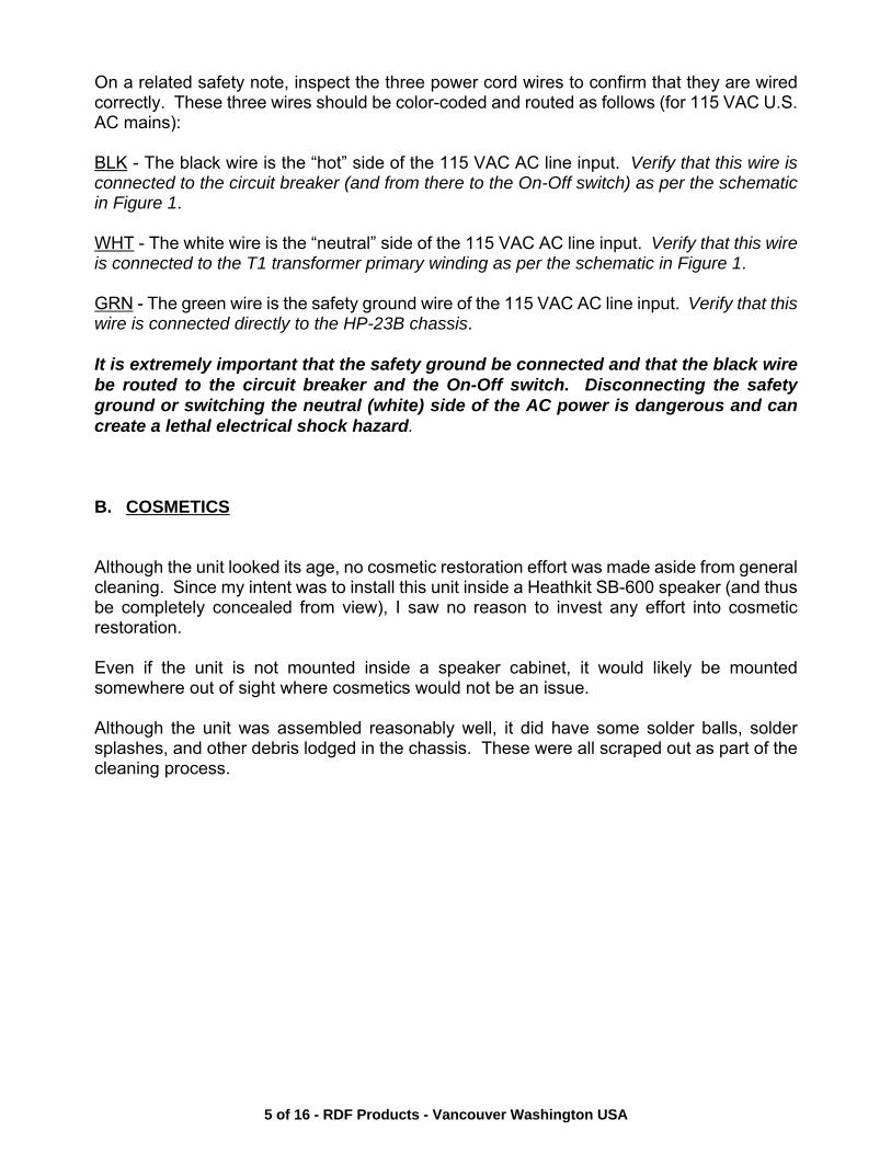
Purely from the standpoint of power dissipation, we could use 1/8 watt 5% carbon filmresistors. However, resistors also have maximum voltage ratings and it would be unsafe touse a 1/8 watt resistor for this high-voltage application. 1/4 watt 5% carbon film resistors havea rated maximum working voltage of 250 VDC which would probably be adequate. However,it is better to use ½ watt 5% carbon film resistors with their higher rated maximum workingvoltage of 350 VDC. The modified diode section of the full-wave voltage doubler is illustratedin Figure 5.
Figure 5 - Full-Wave Voltage DoublerModified to Include 1N4007 Silicon Diodes
and Shunt Voltage Equalizing Resistors
9 of 16 - RDF Products - Vancouver Washington USA
SECTION V - ELECTROLYTIC CAPACITOR REPLACEMENT
A. OVERVIEW
Electrolytic capacitors (especially high-voltage ones) are likely not to be reliable after 40+years of service. Although the electrolytic capacitors in my HP-23B were functional, I decidedto replace them for this reason.
Of all the HP-23B restoration tasks, replacing the seven electrolytic capacitors turned out tobe the most difficult and time consuming. Although high-voltage electrolytic capacitors are stillavailable, there are no longer any direct fit/form/function replacements for the original 1960s-vintage electrolytic capacitors employed in the HP-23B. As a result, adaptations must bemade to accommodate the different sizes and footprints of modern electrolytic capacitors. On the positive side, modern electrolytic capacitors are much smaller, better performing, andmore reliable than their 1960s-vintage predecessors. Since electrolytic capacitors haveservice lives that are much shorter than nearly all other components aside from vacuum tubesand dial lights, I chose premium-grade replacements.
In the following paragraphs, the important characteristics of high-voltage electrolytic capacitorsare discussed, followed by identification of specific modern substitutes for the obsoleteoriginals. Suggestions are then made as to how to install these modern substitutes in the HP-23B.
B. IMPORTANT CHARACTERISTICS OF ELECTROLYTIC CAPACITORS
1. Capacitance and Voltage Rating - Replacement electrolytic capacitors should havecapacitances and voltage ratings equal to or greater than the originals.
2. Service Life - The service life of electrolytic capacitors is typically in the order ofthousands of hours, which surprisingly is only somewhat better than that of vacuumreceiving tubes. Service life is highly dependent upon operating temperature, appliedvoltage, and applied ripple current. When operated conservatively, electrolytic capacitorslast far longer than when they are operated near their maximum ratings.
3. Temperature Rating - The original electrolytic capacitors employed in the HP-23B (andmost non-military electronic equipment built in the 1960s) are rated for operation up to+85EC. Keeping in mind that the service life of electrolytic capacitors is typically in theorder of thousands of hours and that this service life degrades at higher temperatures, Irecommend that premium grade capacitors rated for operation up to +105EC be used forlongest service life.
10 of 16 - RDF Products - Vancouver Washington USA
4. ESR (Equivalent Series Resistance) - Since electrolytic capacitors dissipate a certainpercentage of the charge applied to them into heat, they are characterized as having anequivalent series resistance. This ESR is frequency sensitive, but is mostly constant overthe frequency range of interest (under 1,000 Hz) for high-voltage power supplies. LowESRs are desirable for good performance and long life.
5. AC Ripple Current - Electrolytic capacitors employed as power supply filters are subjectto AC ripple current as a consequence of the fact that there is always some AC ripplevoltage across them. Since this ripple current flows through the capacitor ESR, heat isgenerated that shortens capacitor life. It is therefore important that electrolytic capacitorsbe selected both for high ripple current capacity and low ESR.
C. REPLACEMENTS FOR C1-C4 (125 uF/500 V)
C1-C4 are the tall 125 uF/500 V electrolytic capacitors visible on the HP-23B chassis top-side(see Figure 2). As per the schematic of Figure 1, C1/C2 are used in the high-voltage supplywhile C3/C4 are used in the low-voltage supply. Since the high-voltage supply imposes themost demanding requirements on these capacitors, we will focus primarily on C1/C2.
A vendor search to locate a 125 uF/500 V replacement electrolytic capacitor wasunsuccessful. However, a premium grade 220 uF/500V manufactured by Vishay (P/NMAL219390101E3) was available from Digi-Key Corp. (P/N 4569PHBK-ND). The relevantspecifications for this capacitor are as follows:
Temperature Range: -25EC to +105ECRated ESR @ 100 Hz: 0.9 ohmsRated Ripple Current (100 Hz/105EC): 1.75 amperes
The rated service life is dependent upon a number of variables, but was very favorablecompared to other capacitors that were also considered.
To determine the suitability of this capacitor for the application at hand, we must first calculatethe overall impedance of this capacitor, which comprises the 0.9 ohm ESR in series with thecapacitive reactance at the 120 Hz ripple frequency (for the full-wave voltage doubler). First,we compute the capacitive reactance:
Xc = 1/(2 x π x F x C) (3) = 6.03 ohms
where Xc is the capacitive reactance, π is 3.14159, F is 120 Hz, and C is 220 uF.
Next, the total impedance is found by vectorially adding Xc and the ESR as follows:
Z = Square Root (Xc x Xc + ESR x ESR) (4) = Square Root (6.03 x 6.03 + 0.9 x 0.9) = 6.10 ohms
11 of 16 - RDF Products - Vancouver Washington USA
According to the HP-23B specifications, the high-voltage ripple is rated at 1% under a 250 mA(presumably typical) load. Since the high-voltage DC output under a 250 mA load is specifiedas 700 volts, 1% ripple corresponds to 7 volts RMS (based on the commonly-accepteddefinition of ripple percentage). Given this to be the case, and given that only half of this 7 voltRMS ripple voltage (Vr) will appear across each capacitor (since C1/C2 are in series), theapproximate ripple current is as follows:
Ir = Vr/Z (5) = 3.5/6.10 = 0.574 amperes
where Ir is the RMS ripple current, Vr is the RMS ripple voltage, and Z is the capacitor totalimpedance as defined in equation (4). Since 0.575 amperes is well below the 1.75 amperecapacitor ripple current rating, we can expect long capacitor service life.
The reason that equation (5) is an approximation is that the ripple voltage has a “sawtooth”rather than sinusoidal characteristic. Since a sawtooth waveform has odd-order harmonics(e.g., at 360 Hz, 600 Hz, 840 Hz, etc.), these harmonics result in additional ripple current sincethe capacitive reactance Xc as defined in equation (3) progressively diminishes at thesehigher frequencies. However, the magnitude of these harmonics also progressivelydiminishes as they increase in order. To account for the additional ripple current contributedby these harmonics we can add 15% or so to the result of equation (5), but even with thisaddition the ripple current is still very comfortably within the capacitor 1.75 ampere rating.
In reality, the above computation overstates ripple current Ir since the substitution of the largercapacitor (220 uF versus 125 uF) substantially reduces the ripple voltage Vr. As a result, themargin of safety is further improved.
Since ripple voltage Vr across C3/C4 used in the low-voltage supply is even lower, this samecapacitor can be used with an even greater margin of safety.
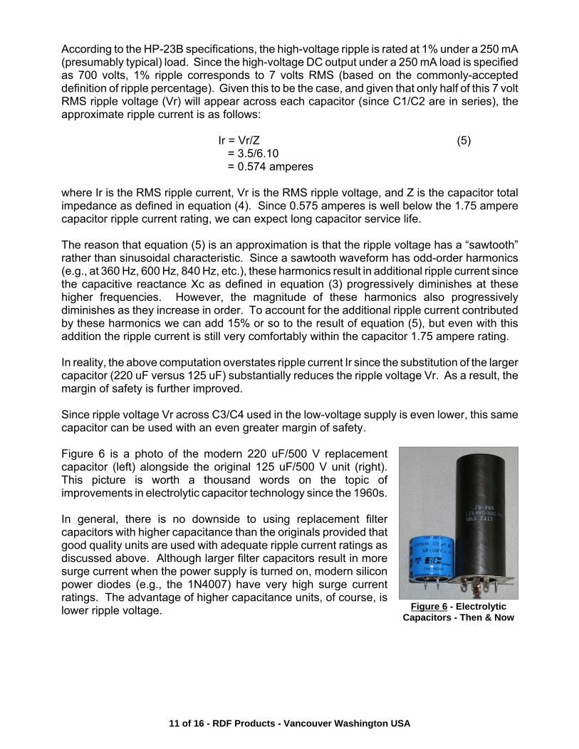
Figure 6 is a photo of the modern 220 uF/500 V replacementcapacitor (left) alongside the original 125 uF/500 V unit (right).This picture is worth a thousand words on the topic ofimprovements in electrolytic capacitor technology since the 1960s. In general, there is no downside to using replacement filtercapacitors with higher capacitance than the originals provided thatgood quality units are used with adequate ripple current ratings asdiscussed above. Although larger filter capacitors result in moresurge current when the power supply is turned on, modern siliconpower diodes (e.g., the 1N4007) have very high surge currentratings. The advantage of higher capacitance units, of course, islower ripple voltage. Figure 6 - Electrolytic
Capacitors - Then & Now
12 of 16 - RDF Products - Vancouver Washington USA
D. MOUNTING C1/C2/C3/C4
Although the 220 uF/500 V capacitors selected to replace C1/C2/C3/C4 offer greatperformance and reliability, they did not fit the HP-23B chassis holes that were punched forthese capacitors. It was thus necessary to fabricate capacitor mounts to handle this.
The most convenient available solution was to simply mount these capacitors on perforatedprototyping boards as per Figures 7 and 8 and then mount these boards onto the chassistopside.
The perforated prototyping board material on-hand had holes drilled on a 0.1" grid and hadcopper-clad on one side. Since copper clad had to be cleared away from the non-groundedcapacitor leads, it would have been better to have used board material with no copper cladon either side. The cut board dimensions are 2.2" x 1.6".
The capacitors employ a “snap-in” lead configuration. To accommodate this mountingconfiguration, board holes were drilled out with a #52 drill bit (slightly larger than 1/16") toprovide a tight lead fit. The capacitors were mounted close to the center of the boards.
Additional holes were drilled at the ends of each board to accommodate the #6 mountingscrews used to secure the original capacitor brackets to the matching chassis holes.
E. REPLACEMENTS FOR C5-C7 (40 uF)
As per the schematic of Figure 1, C5 is a 40 uF/450 V electrolytic used as the final output filtercapacitor for the low-voltage power supply. Similarly, C6 and C7 are 40 uF/150 V electrolyticsused to filter the -130 V bias supply output. As per Figure 3, all three of these capacitors areaxial lead types.
The demands placed on C5-C7 are far more modest than those placed on C1-C4 discussedabove. Since C5 follows the 6 H filter choke used in the low-voltage supply, ripple current islow. Since C6 and C7 filter the low-ripple -130 V bias supply output, they likewise are subject
13 of 16 - RDF Products - Vancouver Washington USA
to only modest ripple current.
Despite the relatively modest demands placed on C5-C7, I still wanted to replace these withpremium grade units selected using same high standards as for C1-C4.
A vendor search found a suitable high-quality 47 uF/450 V replacement for C5 manufacturedby Panasonic (P/N EEUEE2W470) and available from Digi-Key Corp. (P/N P13677-ND). Therelevant specifications for this capacitor are as follows:
Temperature Range: -25EC to +105ECRated ESR @ 120 Hz: 6.8 ohmsRated Ripple Current (120 Hz/105EC): 0.42 amperes
Given the modest price and small size of this C5 replacement, I decided to also use this samecapacitor to replace C6 and C7 as well (even though C6 and C7 require only 150 Vcapacitors).
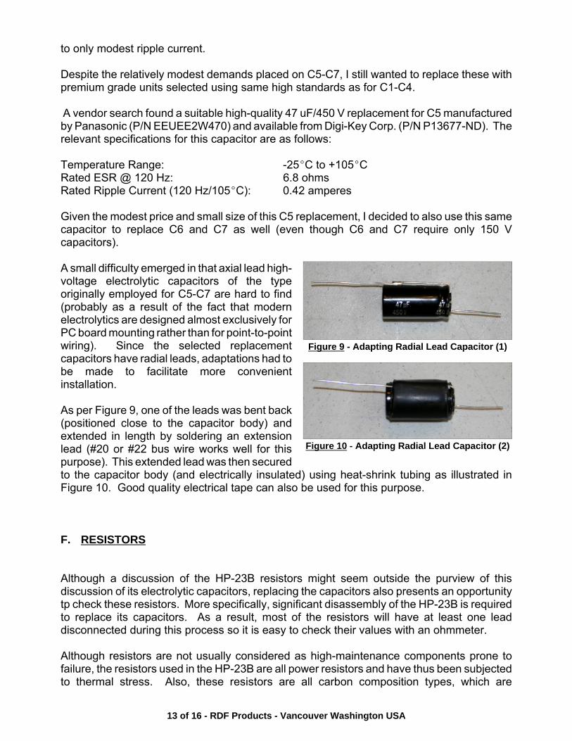
A small difficulty emerged in that axial lead high-voltage electrolytic capacitors of the typeoriginally employed for C5-C7 are hard to find(probably as a result of the fact that modernelectrolytics are designed almost exclusively forPC board mounting rather than for point-to-pointwiring). Since the selected replacementcapacitors have radial leads, adaptations had tobe made to facilitate more convenientinstallation.
As per Figure 9, one of the leads was bent back(positioned close to the capacitor body) andextended in length by soldering an extensionlead (#20 or #22 bus wire works well for thispurpose). This extended lead was then securedto the capacitor body (and electrically insulated) using heat-shrink tubing as illustrated inFigure 10. Good quality electrical tape can also be used for this purpose.
F. RESISTORS
Although a discussion of the HP-23B resistors might seem outside the purview of thisdiscussion of its electrolytic capacitors, replacing the capacitors also presents an opportunitytp check these resistors. More specifically, significant disassembly of the HP-23B is requiredto replace its capacitors. As a result, most of the resistors will have at least one leaddisconnected during this process so it is easy to check their values with an ohmmeter.
Although resistors are not usually considered as high-maintenance components prone tofailure, the resistors used in the HP-23B are all power resistors and have thus been subjectedto thermal stress. Also, these resistors are all carbon composition types, which are
Figure 9 - Adapting Radial Lead Capacitor (1)
Figure 10 - Adapting Radial Lead Capacitor (2)
14 of 16 - RDF Products - Vancouver Washington USA
significantly less stable in value than the more modern carbon film types.
The resistors in my HP-23B all measured on the high side of their nominal values, in somecases having drifted outside the 10% tolerance specification. However, the values had notchanged enough to warrant replacing any of them.
The high-voltage supply bleeder resistors (R1-R4; 100k/2W) are the most critical. Althougha modest upward change in their values is of no great concern, it is important that their valuestrack with each other reasonably well.
To explain, if the parallel value of R1/R2 is significantly different than the parallel value ofR3/R4, there will be an unequal voltage division across C1 and C2 (“voltage hogging”). Asa result, voltage appearing across one of these two capacitors might come close to or exceedits 500 V rating. To deal with this issue in my HP-23B, I regrouped these resistors so that thetotal resistance value of each leg was nearly the same.
Any resistor that is excessively out of tolerance (i.e., by more than 20% of its nominal value)should be replaced. Similarly, resistors that appear burned or “cooked” should also bereplaced. On the positive side, resistors employed in extensively used 40+ year oldequipment are fully aged and will likely not drift in value much further.
15 of 16 - RDF Products - Vancouver Washington USA
SECTION VI - PHOTOS OF FULLY RECONDITIONED HP-23B AND VENDOR NOTES
A. CHASSIS PHOTOS
Figure 11 is an underside photo of the fully reconditioned HP-23B (see Figure 3 shot prior toreconditioning for comparison). Note that C5-C7 are staked-down to the chassis using RTV.(RTV is a form of silicone sealant). I used Permatex Part 66B (which is non-corrosive andavailable in many hardware and auto supply stores), but many other types are equallysuitable. Note also the new 1N4007 rectifier diodes with their added shunt voltage equalizingresistors. Finally, note that cable ties are used as appropriate to secure wires and cablestogether.
Figure 12 is a topside photo of this same unit (see Figure 2 shot prior to reconditioning forcomparison). Note the replacement capacitors for C1-C4 and their mounts.
B. PARTS VENDORS
As discussed above, I purchased the necessary parts from Digi-Key Corp. since they havean excellent selection of capacitors. Other parts vendors with good parts selections andreasonable minimum order requirements are Jameco Electronics and Mouser Electronics.Contact information is as follows: