44
Rectangular Waveguides Dr. S. Cruz-Pol INEL 6216 University of Puerto Rico Mayagüez
| Date post: | 15-Apr-2017 |
| Category: |
Engineering |
| Upload: | khan-yaseen |
| View: | 342 times |
| Download: | 0 times |

Rectangular Waveguides
Dr. S. Cruz-PolINEL 6216University of Puerto RicoMayagüez

Waveguide components
Figures from: www.microwaves101.com/encyclopedia/waveguide.cfm
Rectangular waveguide
Waveguide to coax adapter
E-teeWaveguide bends

More waveguides
http://www.tallguide.com/Waveguidelinearity.html

Uses
To reduce attenuation loss High frequencies High power
Can operate only above certain frequencies Acts as a High-pass filter
Normally circular or rectangular We will assume lossless rectangular
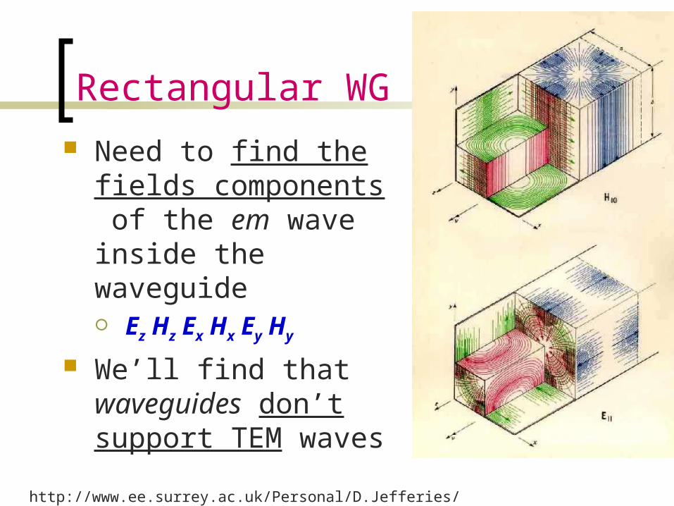
Rectangular WG Need to find the fields
components of the em wave inside the waveguide Ez Hz Ex Hx Ey Hy
We’ll find that waveguides don’t support TEM waves
http://www.ee.surrey.ac.uk/Personal/D.Jefferies/wguide.html
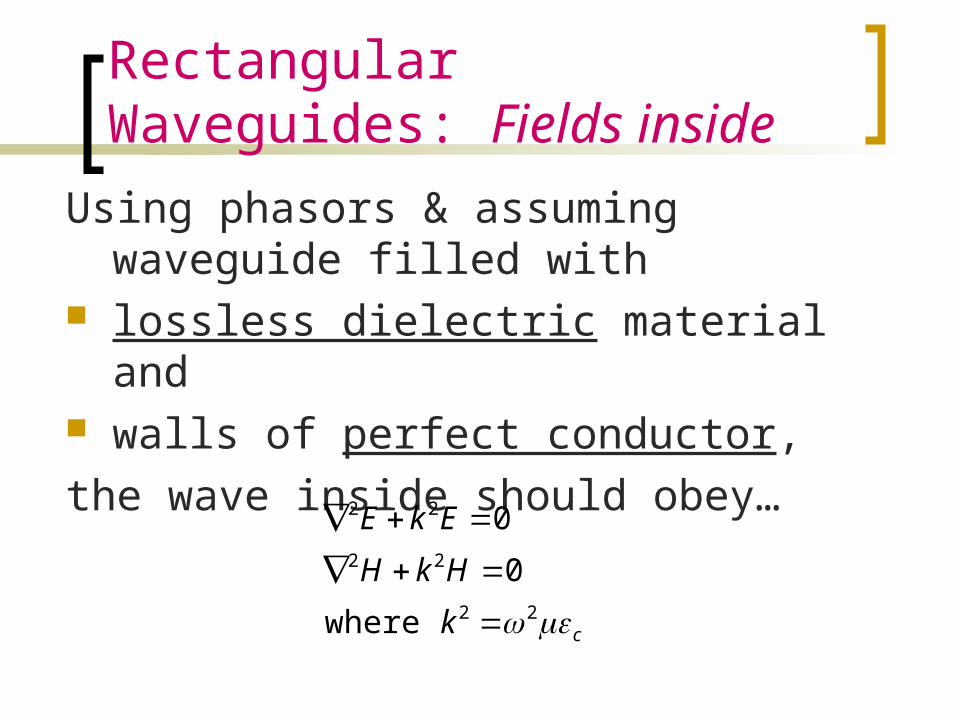
Rectangular Waveguides: Fields inside
Using phasors & assuming waveguide filled with
lossless dielectric material and walls of perfect conductor, the wave inside should obey…
ck
HkH
EkE
22
22
22
where
0
0

Then applying on the z-component…
2
22
2
2
2
2
2
:obtain we wherefrom)()()(),,(
:Variables of Separation of methodby Solving
0
kZZ
YY
XX
zZyYxXzyxE
EkzE
yE
xE
''''''
z
zzzz
022 zz EkE
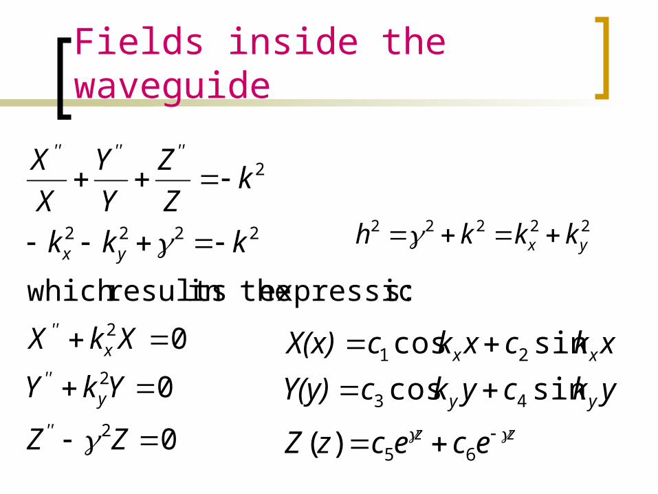
Fields inside the waveguide
0
0
0
:sexpression in the resultswhich
2
2
2
2222
2
ZZ
YkY
XkX
kkk
kZZ
YY
XX
''
y''
x''
yx
''''''
zz
yy
xx
ececzZ
ykcykcY(y)xkcxkcX(x)
65
43
21
)(
sincossincos
22222yx kkkh

Substituting
zz
yy
xx
ececzZ
ykcykcY(y)xkcxkcX(x)
65
43
21
)(
sincossincos
)()()(),,( zZyYxXzyxEz
zyyxxz
zyyxxz
zzyyxxz
eykBykBxkBxkBH
eykAykAxkAxkAE
z
ececykcykcxkcxkcE
sincossincos
,field magnetic for theSimilarly
sincossincos
:direction-in traveling waveat the lookingonly If
sincossincos
4321
4321
654321

Other componentsFrom Faraday and Ampere Laws we can find the
remaining four components:
22222
22
22
22
22
yx
zzy
zzx
zzy
zzx
kkkh
wherey
Hhx
EhjH
xH
hyE
hjH
xH
hj
yE
hE
yH
hj
xE
hE
*So once we know Ez and Hz, we can find all the other fields.

Modes of propagationFrom these equations we can conclude: TEM (Ez=Hz=0) can’t propagate.
TE (Ez=0) transverse electric In TE mode, the electric lines of flux are
perpendicular to the axis of the waveguide
TM (Hz=0) transverse magnetic, Ez exists In TM mode, the magnetic lines of flux are
perpendicular to the axis of the waveguide.
HE hybrid modes in which all components exists

TM Mode
Boundary conditions: ,axE
,byE
z
z
0at 00at 0
Figure from: www.ee.bilkent.edu.tr/~microwave/programs/magnetic/rect/info.htm
zyyxxz eykAykAxkAxkAE sincossincos 4321
zjyxz eykxkAAE sinsin42
From these, we conclude: X(x) is in the form of sin kxx, where kx=m/a, m=1,2,3,… Y(y) is in the form of sin kyy, where ky=n/b, n=1,2,3,… So the solution for Ez(x,y,z) is

TM Mode
Substituting
222
sinsin
bn
amh
where
eyb
nxa
mEE zjoz
22 k
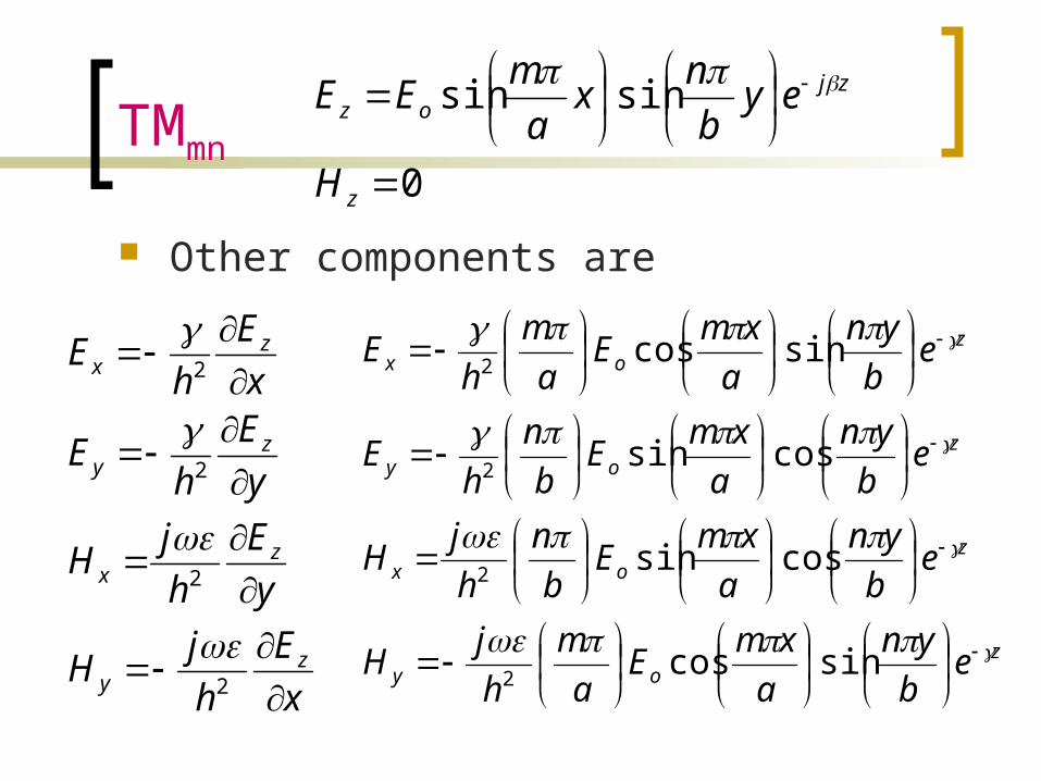
TMmn
Other components are
xE
hjH
yE
hjH
yE
hE
xE
hE
zy
zx
zy
zx
2
2
2
2
zoy
zox
zoy
zox
eb
yna
xmEa
mhjH
eb
yna
xmEb
nhjH
eb
yna
xmEb
nh
E
eb
yna
xmEa
mh
E
sincos
cossin
cossin
sincos
2
2
2
2
0
sinsin
z
zjoz
H
eyb
nxa
mEE

TM modes
The m and n represent the mode of propagation and indicates the number of variations of the field in the x and y directions
Note that for the TM mode, if n or m is zero, all fields are zero.
See applet by Paul Falstadhttp://www.falstad.com/embox/guide.html

TM Cutoff
The cutoff frequency occurs when
Evanescent:
Means no propagation, everything is attenuated
Propagation:
This is the case we are interested since is when the wave is allowed to travel through the guide.
222
222
bn
am
kkk yx
22
222
121or
0then When
bn
amf
jb
na
m
c
c
0 and When 22
2
bn
am
0 and When 22
2
j
bn
am

Cutoff
The cutoff frequency is the frequency below which attenuation occurs and above which propagation takes place. (High Pass)
The phase constant becomes
2222 1'
ff
bn
am c
22
2'
bn
amuf mnc
fc,mn
attenuation
Propagationof mode mn

Phase velocity and impedance
The phase velocity is defined as
And the intrinsic impedance of the mode is
fu
u pp
2
'
2
1'
ff
HE
HE c
x
y
y
xTM

Summary of TM modesWave in the dielectric medium
Inside the waveguide
/'
'/' u
2
1'
ffc
TM
2
1
'
ffc
/
1'2
ff
uc
p
2
1'
ffc
fu /''
/1'/' fu
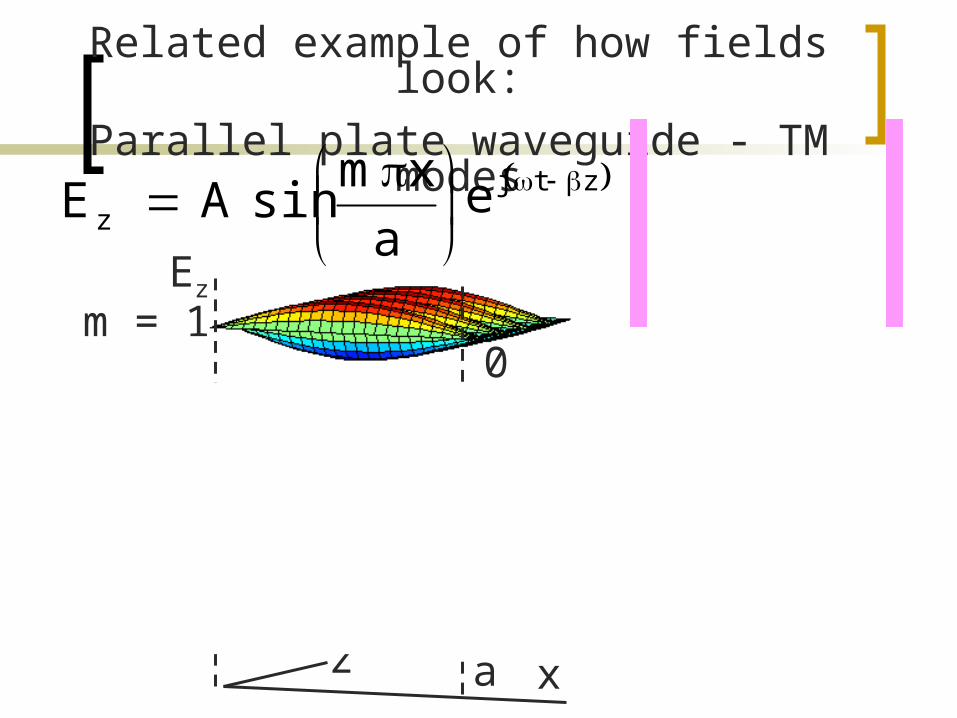
Related example of how fields look:Parallel plate waveguide - TM modes
a
xmsinAEz ztje
0 a x m = 1
m = 2
m = 3xz a
Ez

TE Mode
Boundary conditions: ,axE
,byE
y
x
0at 00at 0
Figure from: www.ee.bilkent.edu.tr/~microwave/programs/magnetic/rect/info.htm
zjyxz eykxkBBH coscos31
From these, we conclude: X(x) is in the form of cos kxx, where kx=m/a, m=0,1,2,3,… Y(y) is in the form of cos kyy, where ky=n/b, n=0,1,2,3,… So the solution for Ez(x,y,z) is
zyyxxz eykBykBxkBxkBH sincossincos 4321

TE Mode Substituting
Note that n and m cannot be both zero because the fields will all be zero.
222
again where
coscos
bn
amh
eyb
na
xmHH zjoz

TEmn
Other components are
zoy
zox
zoy
zox
eb
yna
xmHb
nhjH
eb
yna
xmHa
mhjH
eb
yna
xmHa
mhjE
eb
yna
xmHb
nhjE
sincos
cossin
cossin
sincos
2
2
2
2
0
coscos
z
zjoz
E
eyb
nxa
mHH
yH
hH
xH
hH
xH
hjE
yH
hjE
zy
zx
zy
zx
2
2
2
2

Cutoff
The cutoff frequency is the same expression as for the TM mode
But the lowest attainable frequencies are lowest because here n or m can be zero.
22
2'
bn
amuf mnc
fc,mn
attenuation
Propagationof mode mn
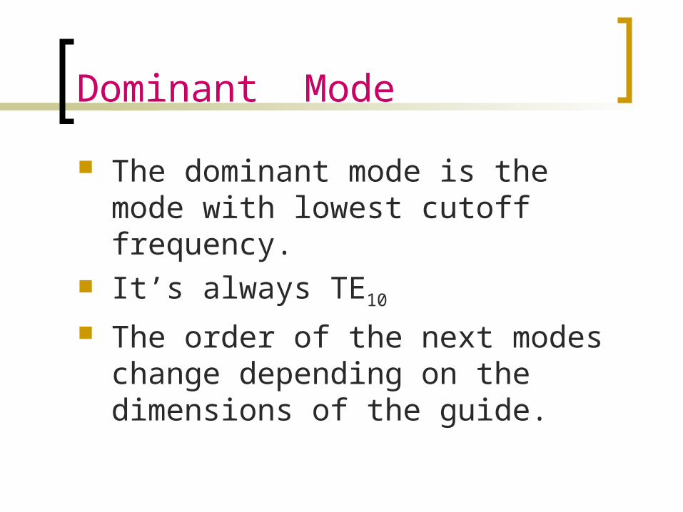
Dominant Mode
The dominant mode is the mode with lowest cutoff frequency.
It’s always TE10
The order of the next modes change depending on the dimensions of the guide.
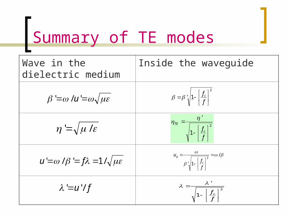
Summary of TE modesWave in the dielectric medium
Inside the waveguide
/'
'/' u
2
1
'
ffc
TE
2
1
'
ffc
/
1'2
ff
uc
p
2
1'
ffc
fu /''
/1'/' fu

Variation of wave impedance
Wave impedance varies with frequency and mode
TE
TM’
fc,mn

Example:
Consider a length of air-filled copper X-band waveguide, with dimensions a=2.286cm, b=1.016cm operating at 10GHz. Find the cutoff frequencies of all possible propagating modes.
Solution: From the formula for the cut-off frequency
22
2'
bn
amuf mnc

Example
An air-filled 5-by 2-cm waveguide has
at 15GHz What mode is being propagated? Find Determine Ey/Ex
V/m 50sin40sin20 zjz eyxE

Group velocity, ug
Is the velocity at which the energy travels.
It is always less than u’
sm
ffuu c
g rad/mrad/s 1'
/1
2
2'uuu gp
zoy e
axmH
ahjE
sin2
http://www.tpub.com/content/et/14092/css/14092_71.htm

Group Velocity
As frequency is increased, the group velocity increases.

Power transmission The average Poynting vector for the waveguide
fields is
where = TE or TM depending on the mode
zEE
HEHEHE
yx
xyyxave
ˆ2
Re21Re
21
22
***
P
a
x
b
y
yxaveave dxdy
EEdSP
0 0
22
2P
[W/m2]
[W]
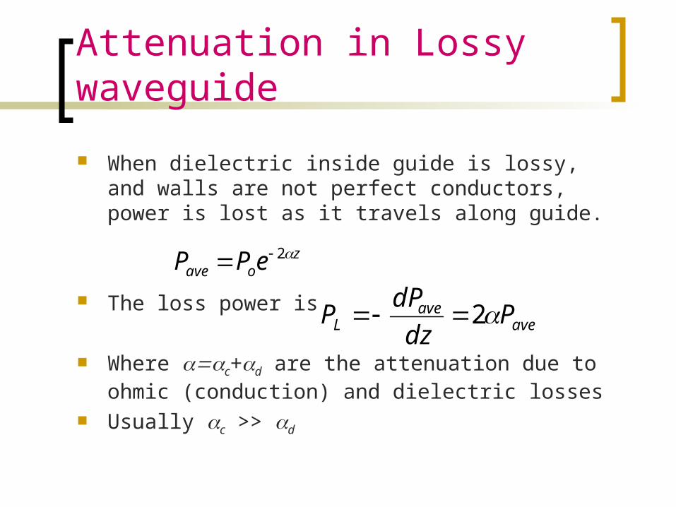
Attenuation in Lossy waveguide
When dielectric inside guide is lossy, and walls are not perfect conductors, power is lost as it travels along guide.
The loss power is
Where c+d are the attenuation due to ohmic (conduction) and dielectric losses
Usually c >> d
zoave ePP 2
aveave
L Pdz
dPP 2
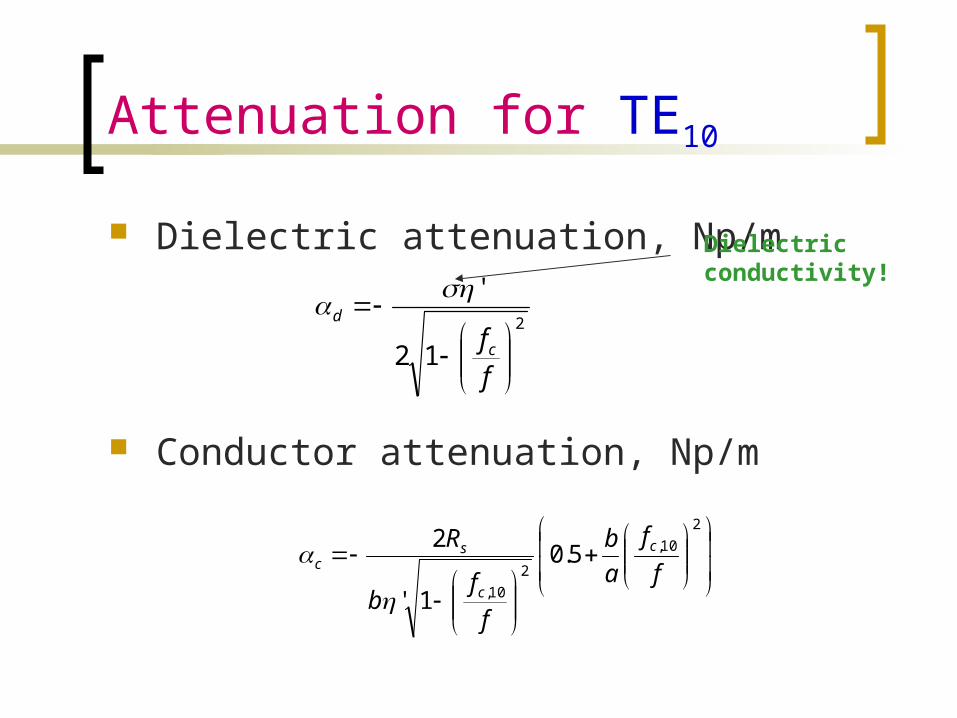
Attenuation for TE10
Dielectric attenuation, Np/m
Conductor attenuation, Np/m
2
12
'
ffc
d
2
10,
210,
5.0
1'
2f
fab
ff
b
R c
c
sc
Dielectric conductivity!
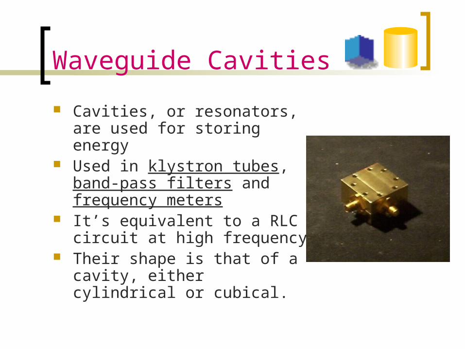
Waveguide Cavities
Cavities, or resonators, are used for storing energy
Used in klystron tubes, band-pass filters and frequency meters
It’s equivalent to a RLC circuit at high frequency
Their shape is that of a cavity, either cylindrical or cubical.

Cavity TM Mode to z
:obtain we wherefrom)()()(),,(
:Variables of Separationby SolvingzZyYxXzyxEz
zkczkczZ
ykcykcY(y)xkcxkcX(x)
zz
yy
xx
sincos)(
sincossincos
65
43
21
2222zyx kkkkwhere

TMmnp Boundary Conditions
,czEE,axE,byE
xy
z
z
0at ,00at 00at 0
From these, we conclude:kx=m/aky=n/bkz=p/c
where c is the dimension in z-axis
2222
2
sinsinsin
cp
bn
amk
wherec
zpb
yna
xmEE oz c

Resonant frequency
The resonant frequency is the same for TM or TE modes, except that the lowest-order TM is TM111 and the lowest-order in TE is TE101.
222
2'
cp
bn
amufr

Cavity TE Mode to z
:obtain we wherefrom)()()(),,(
:Variables of Separationby SolvingzZyYxXzyxH z
zkczkczZ
ykcykcY(y)xkcxkcX(x)
zz
yy
xx
sincos)(
sincossincos
65
43
21
2222zyx kkkkwhere

TEmnp Boundary Conditions
,byE
,axE,czH
x
y
z
0at ,0
0at 00at 0
From these, we conclude:kx=m/aky=n/bkz=p/c
where c is the dimension in z-axis
cyp
byn
axmHH oz
sincoscosc
Quality Factor, Q
The cavity has walls with finite conductivity and is therefore losing stored energy.
The quality factor, Q, characterized the loss and also the bandwidth of the cavity resonator.
Dielectric cavities are used for resonators, amplifiers and oscillators at microwave frequencies.

A dielectric resonator antenna with a cap for measuring the radiation efficiency
Univ. of Mississippi
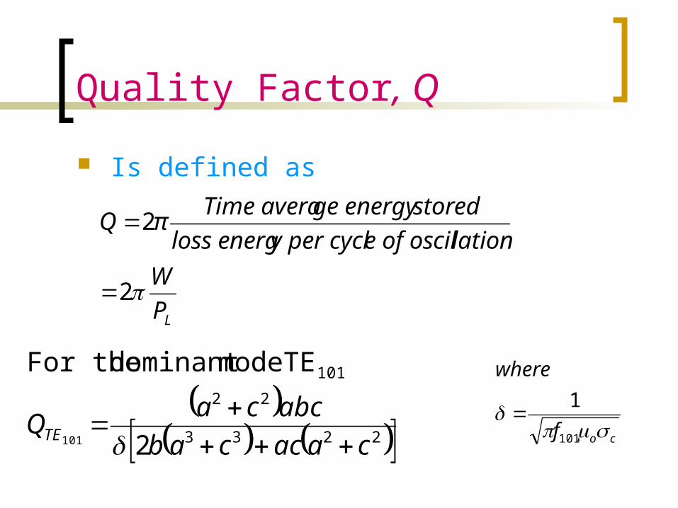
Quality Factor, Q
Is defined as
2233
22
101
2
TE modedominant For the
101 caaccababccaQTE
cof
where
101
1
LPW
latione of oscily per cyclloss energstoredge energy Time averaπQ
2
2

ExampleFor a cavity of dimensions; 3cm x 2cm x 7cm filled with
air and made of copper (c=5.8 x 10⁷) Find the resonant frequency and the quality factor
for the dominant mode.Answer:
GHzfr 44.571
20
31
2103 22210
6
9106.1
)1044.5(1
co
378,568
7373732272373
2233
22
101
TEQ
GHzfr 970
21
31
2103 22210
110


![TECHNICAL INFORMATION TD-00036d2xunoxnk3vwmv.cloudfront.net/uploads/TD-00036K.pdf[9] IEC 60153-3: 1964, “Hollow metallic waveguides, Part 3: Relevant specifications for flat rectangular](https://static.documents.pub/doc/80x56/611c26b42a693235690a3389/technical-information-td-9-iec-60153-3-1964-aoehollow-metallic-waveguides.jpg)


