+ All Categories
Home > Documents > Recycling of Carbon Fibres From Epoxy Composites · fibre polymer composites was improved to about...

Recycling of Carbon Fibres From Epoxy Composites · fibre polymer composites was improved to about...

Date post: 14-Mar-2020
Category:
Upload: others
View: 6 times
Download: 0 times
Share this document with a friend
10
Recycling of Carbon Fibres From Epoxy Composites João Pedro dos Santos Carvalho Department of Chemical Engineering, Instituto Superior Técnico Abstract The aim of this work was the recuperation of carbon fibres from an aviation composite. The acid solvolysis with nitric acid was the method chosen. Various concentrations of nitric acid were utilised to various composite weight/volume of solution ratio of composite. The samples were also exposed to ultraviolet treatments to simulate atmospheric conditions. After recuperating the carbon fibres, these were submitted to various characterization tests in order to conclude which method is better to obtain carbon fibres similar to virgin carbon fibres. The carbon fibres were submitted to Raman spectroscopy, thermogravimetry, X-ray diffraction, infrared spectroscopy, mechanical tests and sweeping electronic microscopy. Virgin fibre samples were submitted to some of the characterization tests and the results were compared to the recuperated carbon fibres. It was observed that ultraviolet rays degrade the resin in the composite and slightly damage the carbon fibre. It was also observed that the fibres submitted to the combination nitric acid at 4M and a ratio of composite weight/volume of solution equal to 4 obtained better results in the characterization tests. Keywords: Carbon fibres, acid solvolysis, nitric acid, composite, ultraviolet.
Transcript

Recycling of Carbon Fibres From Epoxy Composites

João Pedro dos Santos Carvalho

Department of Chemical Engineering, Instituto Superior Técnico

Abstract

The aim of this work was the recuperation of carbon fibres from an aviation composite. The acid

solvolysis with nitric acid was the method chosen. Various concentrations of nitric acid were utilised to

various composite weight/volume of solution ratio of composite. The samples were also exposed to

ultraviolet treatments to simulate atmospheric conditions.

After recuperating the carbon fibres, these were submitted to various characterization tests in order to

conclude which method is better to obtain carbon fibres similar to virgin carbon fibres. The carbon

fibres were submitted to Raman spectroscopy, thermogravimetry, X-ray diffraction, infrared

spectroscopy, mechanical tests and sweeping electronic microscopy.

Virgin fibre samples were submitted to some of the characterization tests and the results were

compared to the recuperated carbon fibres.

It was observed that ultraviolet rays degrade the resin in the composite and slightly damage the

carbon fibre. It was also observed that the fibres submitted to the combination nitric acid at 4M and a

ratio of composite weight/volume of solution equal to 4 obtained better results in the characterization

tests.

Keywords: Carbon fibres, acid solvolysis, nitric acid, composite, ultraviolet.

1. Introduction CFRP is lightweight and easier to

manipulate into shapes than other materials,

including various metals, and it lasts longer

than any other material. That is actually a great

problem. Carbon fibre, which at its most basic

form is carbon graphite, will last virtually

forever. The material is typically not

biodegradable or photo-degradable. The

problem is made worse by the fact that unlike

plastics, aluminium and many other materials,

CFRPs will not degrade, and it is extremely

difficult to recycle. There are, however,

industries that have methods of recycling

CFRPs, but the results are still unsatisfactory.

Yang et al. (2012) verified that using

poly(ethylene glycol) (PEG)/NaOH is highly

efficient at recycling epoxy resins. They

conclude that the main reaction mechanism is

a ester hydrolysis accompanied by a

transetherification process and the most

plausible mechanism is as follows:

Fig. 1 – Plausible reaction mechanism for

solubilisation of epoxy resin using PEG-

200/NaOH

The exact solubilisation products were

investigated using ESI-MS (electrospray

ionization-mass spectrometry) that mainly

include:

Fig. 2 – Solubilisation product obtained by

PEG-200/NaOH reaction

Yang et al. also stated that the

solubilisation rate in this process is better than

the solubilisation rate obtained by Gersifi et al.

(2003).[11]

Gersifi et al. (2003) stated that the

association of titanium (IV) n-butoxide with

diethyleneglycol proved effective in solubilising

epoxy resins. The depolymerisation of the

model matrix and the composite waste are

pushed to the monomer stage and are mainly

constituted by esterdiols, tetraalcohols and

excess of glycol. It was also studied the

solvolysis with monoethanolamine and it was

observed that the reaction is more effective but

its products are solid. Characterization of the

depolymerisation products by NMR (nuclear

magnetic resonance) and MALDI-TOF (matrix-

assisted laser desorption/ionization - time of

flight mass spectrometer) has confirmed the

reaction mechanism of transesterification,

similar to those observed by Yang et al.

(2012), and the presence of other alcoholysis

side reactions.[1]

Palmer et al. (2009) and Pickering et al.

(2006) used the mechanical recycling

approach, which involves breaking down the

composite by shredding, crushing, milling or

other similar mechanical processes and

segregating the resulting scrap pieces, by

sieving, into powdered products (rich in resin)

and fibrous products (rich in fibres). These

recycled composites are usually re-

incorporated in new composites, as filler or

reinforcement, and used in construction

industry, as fillers for asphalt or as mineral

sources for cement. However, this method

reduces significantly the mechanical properties

of the fibres and limits the possibilities for re-

manufacturing.[7, 8]

Meyer et al. (2009) used pyrolysis as a

recycling method. During pyrolysis, the

composite is heated up to 450ºC to 700ºC in

an inert atmosphere. While the fibres are inert

and are eventually recovered, the resin is

volatilized into lower weight molecules..[5, 6]

Pinero-Hernanz et al. (2008) tried various

supercritical fluids to dissolve the resin and

obtained interesting results. However this

method is very expensive to use in industry,

because of the high temperature and the high

pressure that is needed to achieve the

supercritical stage of a fluid.[9, 10]

Kumar et al. (2002) observed extensive

erosion of the epoxy resin when CFRPs are

exposed to ultraviolet radiation and/or

condensation. While the longitudinal fibre-

dominated properties are not affected for the

exposure durations investigated, it was noted

that extensive matrix erosion would ultimately

limit effective load transfer to the reinforcing

fibres and lead to the deterioration of

mechanical properties even along the fibre

dominated material direction.[2]

Lee et al. (2011) proposed and adapted a

circulating flow reactor to a recycling process

for carbon fibre from carbon fibre reinforced

epoxy composite. Lee at al. proposed a

recycling system that was composed of

hexahedral circulating flow reactor made of

quartz, teflon supporter, acid resistance pump

and auxiliaries. They concluded that the

circulating flow reactor most effectively

recycled carbon fibre at 12M of concentration

of nitric acid aqueous solution, 90ºC of

decomposition temperature, 1.8L of nitric acid

aqueous solution per 100g composite and

1.0cm/sec of linear flow rate of circulating

solution. They observed that the liquid phased

decomposition product was a mixture of

nitrated compounds and the tensile strength

loss of the recycled single carbon fibre was

2.91%.[3]

Feraboli et al. (2011) bathed the

composites in boiling sulfuric acid to separate

the fibres from the resin. They observed that

the recycled reinforcement consisted of long

fibres arranged in a random, entangled mat.

They concluded that the recycled panels show

trends and traits similar to those of advanced

carbon fibre and that with further development

efforts, it is possible to realign the recycled

long fibres and re-establish their original

performance.[12]

Shi et al. (2012) recycled glass and carbon

fibres using superheated steam. These fibres

were then surface treated for reuse as fibre-

reinforced polymer composite. They observed

that most residual resin impurities were

removed by the surface treatment and that the

treatment did no adverse effect on bending

strength. The mechanical properties of the

treated composites were determined and

compared with those of recycled reinforced

polymers. The bending strengths of recycled

reinforced polymers were very low, compared

to that of virgin glass fibre-reinforced polymer

and that of virgin carbon fibre-reinforced

polymer. The bending strength of treated glass

fibre polymer composites was improved to

about 90% of that of the virgin glass fibre one,

and the bending strength of the treated carbon

fibre polymer composites was improved to

about 80% of that of the virgin carbon fibre

one.[13]

Akonda et al. (2011) used chopped

recycled carbon fibres from Recycled Carbon

Fibre Ltd., UK, to produce yarns of comingled

carbon fibre and polypropylene blended with

matrix polypropylene staple fibres using a

modified carding and wrap spinning process.

They observed with microscopic analysis that

more than 90% of the recycled carbon fibres

were aligned along the yarn axis and

thermoplastic composite test specimens

fabricated from the wrap-spun yarns had 15–

27.7% recycled carbon fibre volume content.

They also observed that similar to the yarn,

greater than 90% of the recycled carbon fibres

comprising each composite sample made,

showed a parallel alignment with the axis of

the test specimens. The mechanical tests

showed that the average values obtained for

tensile, and flexural strengths were 160 MPa

and 154 MPa, respectively for composite

specimens containing 27.7% recycled carbon

fibres by volume. Akonda et al. concluded that

with such mechanical properties, thermoplastic

composites made from recycled carbon fibres

could be used as low cost materials for many

non-structural applications.[14]

McNally et al. (2007) used reclaimed

carbon fibres obtained from the CARBON-

CLEAN® technology, a thermochemical

process that recovers 95% of the CF, to

manufacture a composite with polyethylene.

They observed that both the Young’s modulus

and ultimate tensile stress increased with

increasing carbon fibre loading, but the

percentage stress at break was unchanged up

to 5 wt % loading, then decreased with further

successive addition of carbon fibres.

McNally et al. concluded that carbon fibres

reclaimed from carbon fibre filled epoxy

prepregs can be readily melt blended with

polyethylene, the carbon fibre was highly

dispersed in the matrix at all loadings and that

the Young’s modulus and tensile strength of

the composites increased by 180 and 27.5%,

respectively, with increasing carbon fibre

loading, suggesting that some degree of

interfacial adhesion is present between the

carbon fibre and polyethylene. They also

concluded that good interfacial adhesion and

wetting between polyethylene and the recycled

carbon fibres is possible, in part, due to the

presence of polar functional groups along the

length of the carbon fibre.[15]

Dannenhauer et al. (2003) proposed a

process for recycling composite materials that

comprise fibres and a matrix by exposing the

composite material to electromagnetic waves

in the form of microwaves. This method is

assisted by suitable solvent, and this solvent

has to be polar. The fibres and the solvent are

put in a TEFLON® container and put inside a

microwave oven with a frequency used

between 300 MHz and 300 GHz. They

observed that the resin was completely

removed from the fibres.[16]

Adam et al. (2014) proposed a method of

extracting and recycling carbon fibres with

furan-2-carbaldehyde. This method consists in

bathing the composite in the solvent and a

swelling agent at a temperature between 50ºC

and 90ºC during about 1 hour to 24 hours. It

was observed that the matrix was removed

and that can be reutilized, and that the fibres

were reusable as well.[17]

2. Experimental Method

The method chosen in this work was the

solvolysis approach[4]

. In this case, different

concentrations of nitric acid were used in

different weight to volume ratios and with

different UV light treatments.[2]

This treatment was performed in a POL-

EKO Apartura UVB oven. Each cycle is

composed by three steps:

Heating to 30ºC and stabilization at that

temperature for 30 minutes;

Heating to 60ºC and stabilization at that

temperature and at 60% humidity for 2

hours and 30 minutes;

Cooling to 25ºC and returning to 0%

humidity and stabilizing at that

temperature for 30 minutes.

The method is carried out in a glass vessel

with a magnetic agitator, at 95ºC for 12 hours

with a 250ml of a nitric acid solution. The nitric

acid solutions were made with a Panreac nitric

acid at 65% (w/w).

Various experiments were carried out to

optimize the method. The variables that were

altered during the optimization process are:

The concentration of nitric acid solution;

The mass of composite to volume of acid

ratio;

The number of cycles of the UV

treatment.

The following table describes the specific

conditions of each experiment.

Table 1 – Conditions of each experiment

[HNO3]

(M)

α (g of

composite/100mL

of solution)

UVB

cycles

Experiment 1 4 4 0

Experiment 2 4 2 0

Experiment 3 6 2 0

Experiment 4 4 2 120

Experiment 5 4 2 249

Experiment 6 2 2 309

Experiment 7 8 6 0

During the experiments, some changes

were observed. At 10 minutes into the reaction,

the liquid solution started showing a light

yellow colour. At 30 minutes into to the

reaction, the solution is bright yellow shows

signs that the viscosity rises. At approximately

1h30 min. the first loose fibres are starting to

show in the liquid, and at approximately 4

hours most of the fibres appear loose from the

matrix.

3. Equipment

The X-Ray diffraction was performed by

using a Philips PW3020, at room temperature,

using Cu Kα radiation (λ= 1.541874 Å)

generated at 40 kV and 30 mA, in the range

(2θ) 10o to 35o, with a step of 3 o/min. with an

aluminium support. The SEM images were

obtained by a FEG microscope. A Instron 5566

was used to do the mechanical tests on the

fibres. A Labram hr evolution Raman

spectrometer was used to do the Raman

spectra. A HATR-FTIR equipment was used to

do the infrared spectra using reflectance

mode (HATR). A Netzsch STA 409 PC

equipment was used to do the TGA spectra.

4. Results

XRD spectra is used to test the structure of

CF’s as shown in Fig. 3. The detailed data are

listed in Table 3.

It is seen that a strong peak ((002) plane)

exists at approximately 2θ = 25o. The interlayer

spacing (d002) and apparent crystallite

thickness (Lc) derived from (002) reflection are

also used as an experimental parameter to

assess the structural properties of the CF’s

Layers of the stacked crystallite are used to

measure the degree of graphitization of CF

determined by Lc/d002.

The value of d002 was calculated using

Bragg’s law, and the crystallite size Lc was

calculated using Scherrer’s formula:

θ

θ

Where θ is the scattering angle, is the

wavelength of the X-rays used (1.541874 Å),

and is the full width at half maximum

intensity (FWHM). The form factor K is 0.9.[18,

20]

Fig. 3 – XRD of carbon fibres with different treatments

Table 2 – XRD results of CFs treated under different reaction conditions

Sample β (o) 2θ(o) Lc (nm) d002 (nm) Lc/d002

Virgin fibres 4.83 26.5 1.7 0.34 5.00

V.F. Pre-treatment 5.41 25.6 1.5 0.35 4.28

C_epoxi 4.13 25.4 2.0 0.35 5.71

C_epoxi_4M_2alfa 5.92 25.9 1.5 0.34 4.41

C_epoxi_4M_UV249_2alfa 5.39 25.7 1.5 0.35 4.28

C_epoxi_4M_4alfa 5.04 26.2 1.6 0.34 4.70

C_epoxi_6M_2alfa 5.56 25.7 1.5 0.35 4.28

Raman spectrogram combines a

prominent surface selectivity with an

exceptional sensitivity to the degree of

structural disorder. Carbon mainly shows two

peaks in the first order (1000–2000cm-1

). One

near 1580cm-1

is corresponding to an ideal

graphitic lattice called G band while the other

near 1360cm-1

is the characteristic peak of sp3

0

500

1000

1500

2000

2500

3000

3500

10 15 20 25 30 35

Inte

nsi

ty

2θ(o)

C_epoxi

C_epoxi_4M

C_Epoxi_4M_UV249

C_epoxi_6M

C_epoxi_4M_4alfa

Virgin Fiber

V. F. Pretreatment

state of C called D band which is due to the

existence of structural disorder.

The D to G band integrated intensity ratio

(ID/IG) is a parameter to quantify the degree of

disorder. Usually, the smaller value of ID/IG

indicates the higher degree of graphitization

of the CF’s.[18, 19, 20, 21]

Fig.4 – Raman spectra of the carbon fibres

Table 3 – Raman results of CFs treated under different reaction conditions

Sample Raman Shift (cm-1

) Area (x10-5

)

ID/IG

FC2M 1347 6.8

2.08 1582 3.3

FC4M 1350 5.1

1.33 1580 3.8

FC4M 120 UV 1348 6.4

1.30 1576 4.9

FC4M 4 alpha 1359 5.8

1.18 1583 4.9

FC6M 1347 9.0

1.35 1571 6.6

FC8M 1358 7.3

1.32 1576 5.5

Virgin Fibre 1345 5.5

1.32 1569 4.1

V. F. Pre-Treatment 1342 7.1

1.20 1574 5.9

Due to limitations of the machine, it was

only possible to test fibres which were 5

centimetres or more long.

Firstly the carbon fibres were glued to a

card specimen holder. Then these specimens

were placed in the machine and underwent a

strain test. The results are exemplified in the

image below (Fig. 5).

After all the specimens were tested, it

estimated the number of fibres in all the

specimen holders so that it was possible to

calculate the Young’s modulus and the

ultimate tensile strength of a single carbon

fibre.

800 1000 1200 1400 1600 1800 2000

Inte

nsi

ty [

a.u

.]

Wavenumbers [1/cm]

CF 2M

CF 4M UV 120

CF 4M

CF 4M 4alfa

CF 6M

CF 8M

Virgin CF

V. F. Pre-treatment

Fig.5- Mechanical test result of a specimen of

carbon fibre

Table 4 – Mechanical properties of the CF

Sample Tensile strength (Mpa) Young's Modulus

(Gpa)

4M 3176 150

4M 4 α 4569 161

6M 4308 221

The ultimate tensile strength corresponded

with the maximum load value and the Young’s

Modulus corresponded with the slope in the

Tensile vs Axial Extension chart.

The values of the ultimate tensile strength

and the Young’s modulus are displayed in the

table 4.

The morphology and geometry are shown

in the SEM figures below:

The diameter measured is approximately

5.5 µm and is assumed that this diameter is

the same among all of the recovered fibres.

The infrared spectra are shown in the

figure 9.

The carbon fibre samples were also

characterized by thermogravimetry under

air, to evaluate the thermal stability after the

recuperation process .The fibres were heated

from 30oC to 1100

oC at 30oC/min using

alumina crucibles. The TGA spectra is shown

in the figure 10 and the fibre degradation

temperatures are shown in the table 5.

Fig.6 – SEM image of Carbon fibre composite

Fig.7 - SEM image of Carbon fibre treated with

a 4M solution of HNO3

Fig.8- SEM image of Carbon fibre with the

diameter measured

0

0,5

1

1,5

2

2,5

3

3,5

0 0,5 1 1,5

Load

(N

)

Extension (mm)

CF 4M test 4

Fig.9- Infrared adsorption spectra of the carbon fibres (virgin and recuperated)

Fig.10- Thermogravimetric analysis spectra of the recuperated carbon fibres

Table 5 – Degradation temperatures of the

carbon fibres

Sample Degradation Temperature (oC)

Virgin CF 767

CF 4M 4alfa 650

CF 4M 120UV A 704

CF 4M 120UV B 754

CF 8M A 638

CF 8M B 654

5. Discusion

The FTIR spectra shows the organic

residue in the fibres, as well as evidence of

CO2 adsorbed in the fibres. Generally, the

recovered carbon fibres show adsorption

bands around 2900 cm-1

and 1700 cm-1

which

are derived from carboxylic acid and carbonyl

functionality respectively. These groups are

formed due to the degradation of the epoxy

resin during the recovery process.[15]

The adsorption band present in all the

recuperated fibres at around 2350 cm-1

corresponds to the CO2 adsorbed. Generally,

the longer the UV treatment, the value of the

CO2 adsorbed in the fibres is higher. This

adsorption band can also correspond to the C-

N triple bond resulting from the nitric acid

attack on the epoxy resin[9]

.

Some fibres show an adsorption band at

around 850 cm-1

, which represents evidence

of epoxy groups[9]

.

The TGA analysis shows that the fibres

treated with UV lose more mass than the fibres

which are not treated with UV, however, they

show more thermal stability than the other

recuperated fibres. This may be because,

during the UV treatment, the graphite

crystallises thus increasing the resistance to

the oxidation process.

0

0,5

1

1,5

2

800 1300 1800 2300 2800

Ab

sorb

ance

Wavenumbers [1/cm]

CF 4M 4alfa CF 6M CF 8M CF 8M Poly CF 2M 309 UV CF 4M

50

100

0 100 200 300 400 500 600 700 800 900 1000 1100

Weig

ht (%

)

Temperature (oC)

CF 4M 4alfa Composite CF 4M 120UV A CF 4M 120UV B CF 8M A CF 8M B Virgin CF

All the samples analyzed in the Raman

show a D to G band integrated intensity ratio

similar to the virgin carbon fibres, except the

samples recovered with the two treatments of

2M concentration of nitric acid and with 309

cycles of UV treatment, which shows a higher

ration, indicating a lower degree of

graphitization. The sample recovered with the

treatment of 4M concentration of nitric acid and

an alpha of 4 shows the lowest integrated ratio,

which indicates a higher degree of

graphitization. The Raman results of this fibre

show that it has less damage and less residue

to the surface[22].

Comparing the Raman of the virgin fibres

and the virgin fibres with a thermal pre-

treatment, it is shown that the fibres with the

treatment show a higher degree of

graphitization, thus the treatment is shown to

increase the strength of the carbon fibre. The

recovered fibre which was treated with a 4M

solution of nitric acid and an alpha of 4 has a

similar integrated intensity ratio in comparison

to the virgin fibre with the thermal pre-

treatment, this tells us that the degree of

graphitization is similar to the virgin fibre with

the thermal pre-treatment.

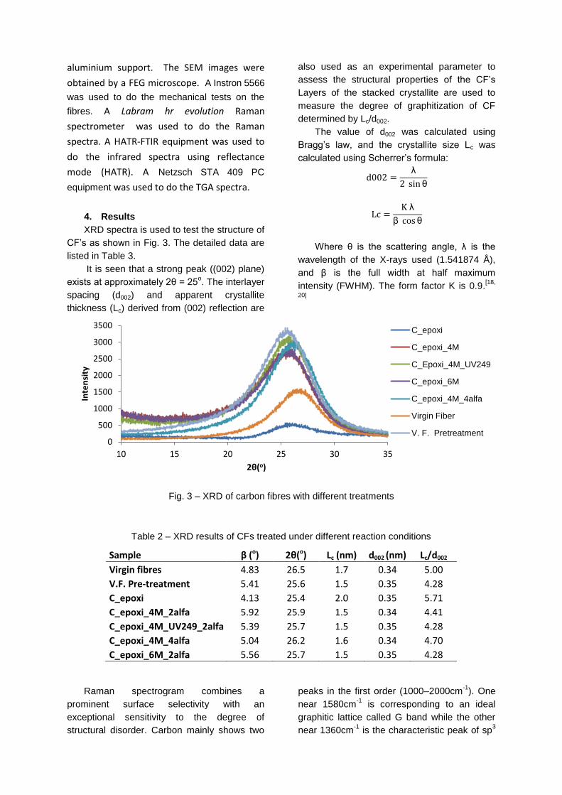
XRD spectra were also used to test the

structure of CFs. The detailed data are listed in

Table 2. It is seen that a strong peak ((002)

plane) exists at a 2θ = 25o. It is found that the

layers of the stacked crystallite of the

recovered CFs are comparable with the virgin

ones. It reveals that the recovered CFs retains

high degree of graphitization of the virgin CFs.

These results indicate that the structure of CFs

is damaged slightly during the recycling

process. Combining the SEM, Raman and

XRD results, it is believed that the structure of

CFs is not damaged dramatically, and this can

be testified by the tensile strength[22]

.

The mechanical tests show that all the

samples are in the gamma of the tabulated

values for virgin fibres and the fibres treated

with 4M of nitric acid and a α = 4 have a higher

ultimate tensile strength. This result backs up

the conclusions of the XRD and the Raman,

however the sample treated with the 6M of

nitric acid shows a higher Young’s modulus.

In the SEM images the results back up the

previous conclusions; the more UV cycles

used, the more resin is removed. But the SEM

images also show that the more cycles used,

the more damage the fibres suffer. It also

shows that, the more concentrated the

solution, more resin is removed and more

damage appears on the fibres.

Without the UV treatment, the fibres

treated with the 4M solution show less damage

on the surface than those treated with the 6M

and 8M solutions, and the loss of resin is

almost the same.

With the UV treatment, the fibres treated

with 309 cycles of UV light, even though they

were treated with a 2M solution, show a lot

more damage than those with less cycles and

a 4M solution.

6. Conclusion

In conclusion, it is possible to recuperate

carbon fibres from an epoxy resin with nitric

acid and that the best concentrations of nitric

acid are between 4M and 6M, the best α is

between 2 and 4 and that the UVB light

treatment is helpful in removing the epoxy

resin, but too much exposure can damage the

carbon fibres.

7. Bibliography

[1] Gersifi, K. E., Destais-Orvoën N., Durand G., Tersac G., Glycolysis of epoxide-amine hardened networks. I. Diglycidylether/aliphatic amines model networks, Polymer (2003); 44: 3795–3801.

[2] Kumar B. G., Singh R. P., Nakamura T., Degradation of carbon fiber-reinforced epoxy composites by ultraviolet radiation and condensation, Journal of Composite Materials, Vol. 36, No. 24/2002.

[3] Lee S. H., Choi H. O., Kim J. S., Lee C. K., Kim Y. K., Ju C. S., Circulating flow reactor for recycling of carbon fiber from carbon fiber reinforced epoxy composite, Korean J. Chem. Eng. (2011); 28(1): 449-454.

[4] Liu, Y.Y., Meng, L.H., Huang, Y.D., Du, J.J., Recycling of carbon/epoxy composites. J. Appl. Polym. Sci.(2004); 94: 1912-1916.

[5] Meyer, L.O., Schulte, K., Grove-Nielsen, E., CFRP-Recycling Following a Pyrolysis Route: Process Optimization and Potential, Journal of Composite Materials (2009); 43: 1121-1132.

[6] Meyer, L.O., Schulte, K., Grove-Nielsen, E., Optimisation of a pyrolysis process for recycling of CFRP's, in: ICCM-16, Japan Society for Composite Materials (2007), Kyoto, Japan.

[7] Palmer, J., Ghita, O.R., Savage, L., Evans, K.E., Successful closed-loop recycling of thermoset composites. Composites: Part A (2009); 40: 490-498.

[8] Pickering, S.J., Recycling technologies for thermoset composite materials - current status. Composites: Part A (2006); 37: 1206-1215.

[9] Pinero-Hernanz, R., Garcia-Serna, J., Dodds, C., Hyde, J., Poliakoff, M., Cocero, M.J., Kingman, S., Pickering, S., Lester, E.,. Chemical recycling of carbon fibre composites using alcohols under subcritical and supercritical conditions. Journal Supercritical Fluids (2008); 46: 83-92.

[10] Pinero-Hernanz, R., Dodds, C., Hyde, J., Garcia-Serna, J., Poliakoff, M., Lester, E., Cocero, M.J., Kingman, S., Pickering, S., Wong, K.H., Chemical recycling of carbon fibre reinforced composites in nearcritical and supercritical water. Composites: Part A (2008); 39: 454-461.

[11 ] Yang, P., Zhou, Q., Yuan, X., Kasteren, J.M.N., Wang, Y., Highly efficient solvolysis of epoxy resin using poly(ethylene glycol)/NaOH systems. Polymer Degradation Stabilisation (2012); 97: 1101-1106.

[12] Feraboli, P., Kawakami, H., Wade, B., Gasco, F., DeOto, L., Masini, A., Recyclability and reutilization of carbon fiber fabric/epoxy composites. Journal of Composite Materials (2011).

[13] Shi, J., Bao, L., Kobayashi, R., Kato, J., Kemmochi, K., Reusing recycled fibers in high-value fiber-reinforced polymer composites: Improving bending strength by surface cleaning, Composites Science and Technology (2012); 72(11):1298-1303.

[14] Akonda, M.H., Lawrence, C.A., Weager, B.M., Recycled carbon fibre-reinforced polypropylene thermoplastic composites, Composites: Part A (2012); 43: 79-86.

[15] McNally, T., Boyd, P., McClory, C. , Bien, D., Moore, I., Millar, B., Davidson, J., Carroll T., Recycled carbon fiber filled polyethylene composites, Journal of Applied Polymer Science, (2007); 107: 2015-2021.

[16] Dannenhauer, F., Grundig, P., Sailer, M.T., Process for recycling fiber composite materials, Patent Nº.: US 6537341 B2 (2003).

[17] Adam, G. A., Recycling carbon fibers from epoxy using solvent cracking, Patent Nº.: US 2014/0023581 A1 (2014).

[18] Zhang, S., Cui, Y., Wu, B., Song, R., Zhou, H. S. J., Chen, X., Liua, J., Cao, L., Control of graphitization degree and defects of carbon blacks through ball-milling, RSC Adv., 2014, 4, 505.

[19] Lobo, A. O., Martin, A. A., Antunes, E.

F., Trava-Airoldi, V. J., Corat, E. J.,

Caracterização de materiais carbonosos por

espectroscopia raman, INPE ePrint:

sid.inpe.br/yolanda/2004/12.08.13.44 v1

2004-12-09.

[20] Li, D., Wang, H., Wang, X., Effect of microstructure on the modulus of PAN-based carbon fibers during high temperature treatment and hot stretching graphitization, J Mater Sci (2007) 42:4642–4649.

[21] Chaudhuri, S. N., Chaudhuri, R. A., Benner, R. E., Penugonda, M. S., Raman spectroscopy for characterization of interfacial debonds between carbon fibers and polymer matrices, Composite Structures 76 (2006) 375–387.

[22] Xu, P., Li, J., Ding, J., Chemical recycling of carbon fibre/epoxy composites in a mixed solution of peroxide hydrogen and N,N-dimethylformamide, Composites Science and Technology 82 (2013) 54–59.


Recommended