Protection relays for primary and secondary distribution Reduced size and light weight Two protocols simultaneously: MODBUS & IEC 60870-5-103 With auto-reclosing, trip circuit supervision and cold load pick up High electromagnetic compatibility SIL
Transcript
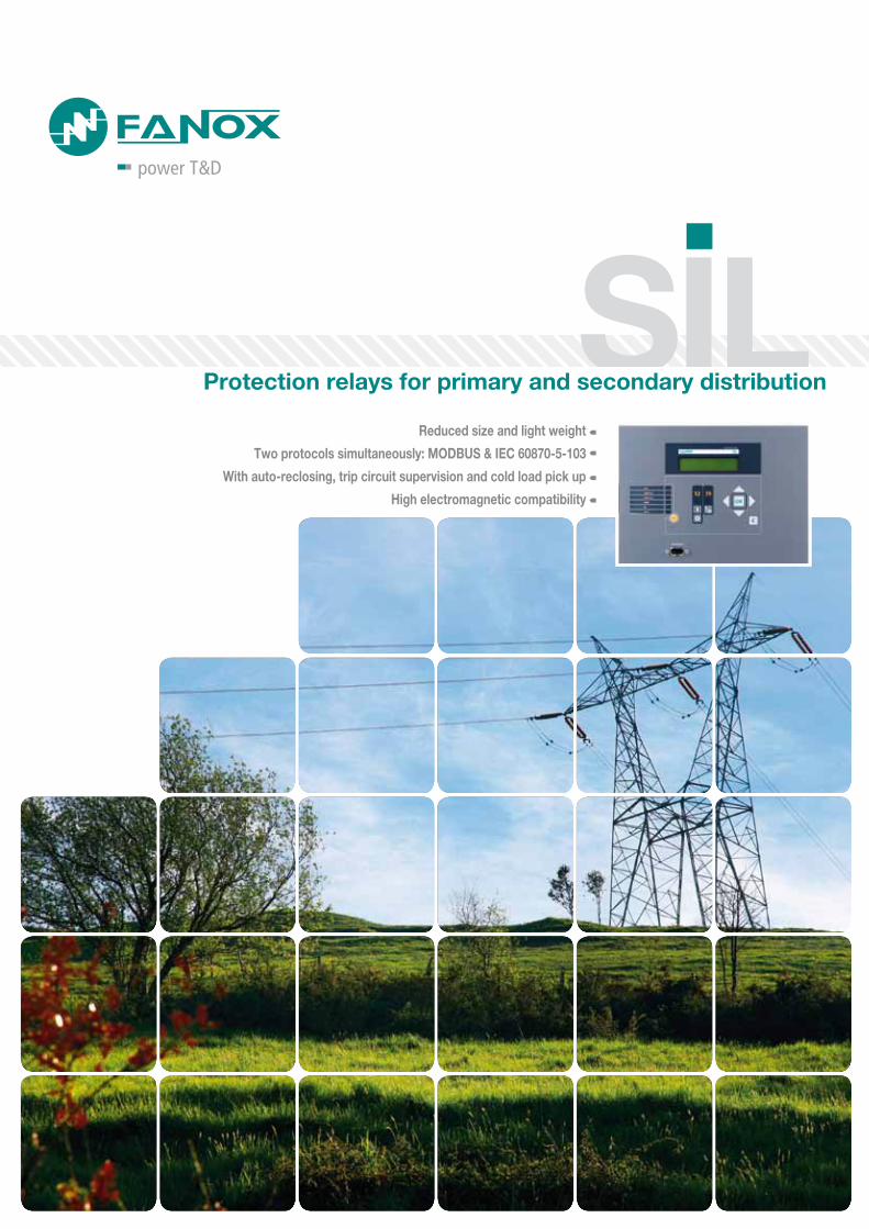
Protection relays for primary and secondary distribution
Reduced size and light weight
Two protocols simultaneously: MODBUS & IEC 60870-5-103
With auto-reclosing, trip circuit supervision and cold load pick up
High electromagnetic compatibility
SIL
Protection relays for primary and secondary distribution. SIL ________4
Protection functions and Standards ______________________________5
Model list______________________________________________ 15
Common elements ___________________________________________ 16
Through creativity, attention to customer needs, a wealth of experience, and extensive research, Fanox consistently del ivers innovative products with unmatched features and performance.
Fanox, as an innovation driver and trendsetter, is establishing itself on the energy market as a powerful manufacturer of numerical protection relays that can be consistently used throughout all applications in the Transmission and Distribution networks.
With the SIA and SIL range operators have their systems firmly and safely under control, and have the basis to implement cost-efficient solutions for all duties in modern, intelligent and “smart” grids.
Protection relays for primary and secondary distribution. SIL ________4
Protection functions and Standards ______________________________5
Model list______________________________________________ 15
Common elements ___________________________________________ 16
4
Protection relays for primary and secondary distribution. SIL
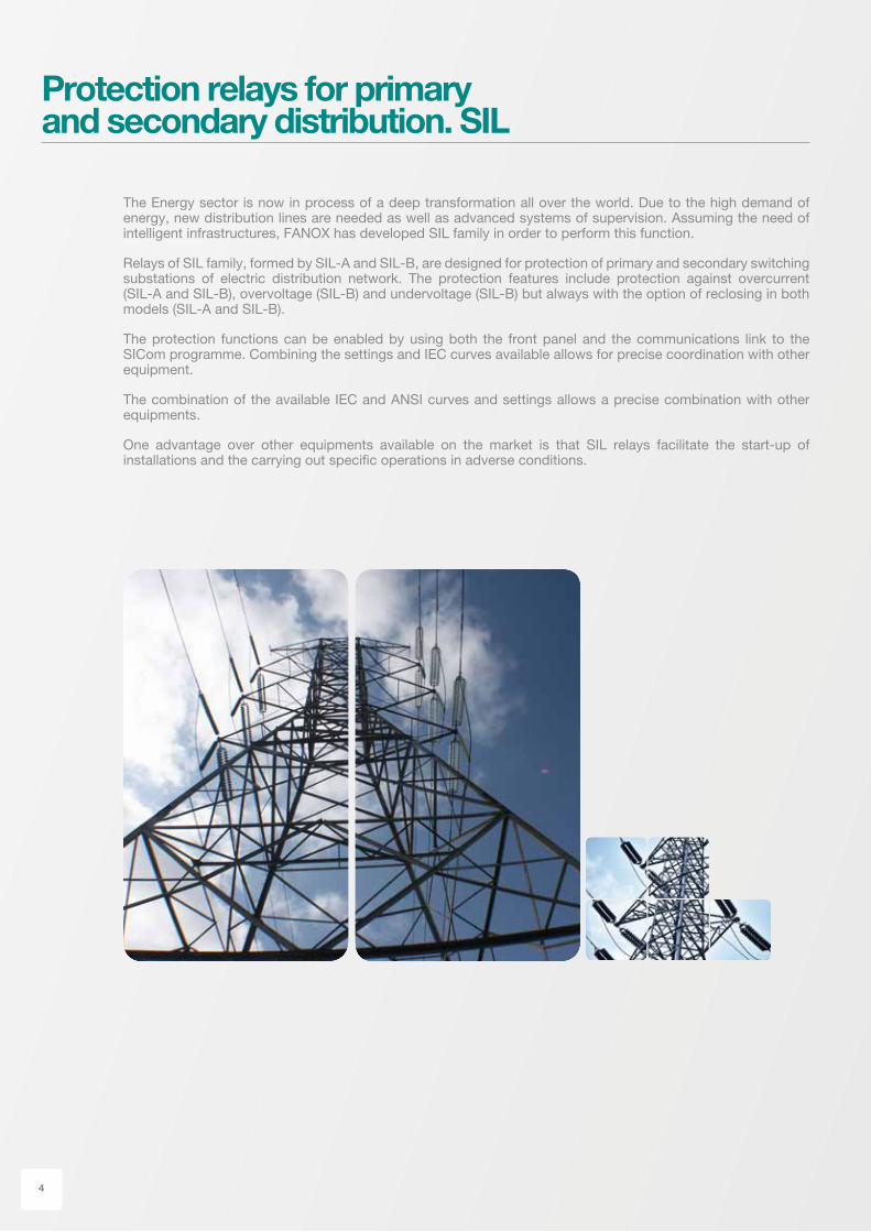
The Energy sector is now in process of a deep transformation all over the world. Due to the high demand of energy, new distribution lines are needed as well as advanced systems of supervision. Assuming the need of intelligent infrastructures, FANOX has developed SIL family in order to perform this function.
Relays of SIL family, formed by SIL-A and SIL-B, are designed for protection of primary and secondary switching substations of electric distribution network. The protection features include protection against overcurrent (SIL-A and SIL-B), overvoltage (SIL-B) and undervoltage (SIL-B) but always with the option of reclosing in both models (SIL-A and SIL-B).
The protection functions can be enabled by using both the front panel and the communications link to the SICom programme. Combining the settings and IEC curves available allows for precise coordination with other equipment.
The combination of the available IEC and ANSI curves and settings allows a precise combination with other equipments.
One advantage over other equipments available on the market is that SIL relays facilitate the start-up of installations and the carrying out specific operations in adverse conditions.
Directional Power ProtectionFunction 32/40Defined time directional power
RecloserFunction 79This function is the responsible of reclosing the breaker when a fault occurs.
Phase directional ProtectionFunction 67PIt uses the voltage between phases as the polarization magnitude and the phase current as the operating variable. If the directional function 67P is not enabled, it behaves as a 51/50P function. The operative time starts when the following conditions are met simultaneously:
- Polarization voltage higher than setting- Phase current higher than setting- Gap between phase current and polarization voltage
is such that the phase current is within the area of the intervention.
Neutral Directional ProtectionFunction 67NIt uses the residual voltage as the polarization magnitude and the residual current as the operating variable. If the directional function 67N is not enabled, it behaves as a 51/50N function.
The operative time starts when the following conditions are met simultaneously:
- Polarisation voltage higher than setting- Residual current higher than setting- Gap between residual current and polarisation voltage
is such that the residual current is within the area of the intervention.
Additional FunctionsFunction 52This function allows monitoring of circuit breaker state and makes a preventive maintenance.Function 50BFThis function allows showing a possible error of the circuit breaker opening.Function 74CSThis function allows the supervision of breaker’s trip circuit.CLP (Cold Load Pick-up)This unit is used in order to avoid non-desirable operations of overcurrent functions when the line is not energized.IRIG-BGPS Time Synchronization Protocol.
Curves IEC 60255-151 and ANSIStandard curves are used for the protection functions51P, 51N, 46, 67P y 67N:- Normally inverse- Very inverse- Extremely inverse- Definite time
StandardsIEC 61000-4-2 Immunity Tests to Electrostatic Discharges IEC 61000-4-3 Immunity Tests to Radiated Radiofrequency Electro-magnetic FieldsIEC61000-4-4 Immunity to Electrical Fast Transients (EFT)IEC 61000-4-5 Immunity to surgesIEC 61000-4-6 Immunity to Conducted RFIEC 61000-4-8 Power frequency magnetic field immunity testIEC 61000-4-9 Immunity to Pulsed Magnetic Fields IEC 61000-4-10 Immunity to Damped Oscillating Magnetic Fields IEC 61000-4-11 Immunity to gaps and variations of AC voltageIEC 61000-4-12 Immunity to damped RF oscillatory wavesIEC 61000-4-14 Voltage fluctuation immunity test IEC 61000-4-17 Residual waves in the power DC input IEC 61000-4-18 Damped oscilatory wave immunity testIEC 61000-4-27 Imbalance IEC 61000-4-29 Voltage dips, short interruptions and voltage variations (direct current)IEC 60255-5 Dielectric Test IEC 60255-5 Isolation resistance test IEC 60255-5 Impulse voltage test EN 60068-2-1 Cold EN 60068-2-2 Dry heat EN 60068-2-14 Change of temperature IEC 60255-21-1 Vibrations tests (sinusoidal) IEC 60255-21-2 Shock and bump tests IEC 60255-21-3 Seismic testsEN 50263 Generic measurement standard for relays and protection equipmentsEN 61000-6-4 Generic standard for emissions in an industrial environmentEN 61000-6-2 Generic standard for immunity in an industrial environmentEN 55011 and EN 55022 RF Emissions IEC 60255-22-1 Immunity to damped RF oscillatory waves
Fanox Quality Management System its certified according to standard ISO 9001:2008
5
SIL-A
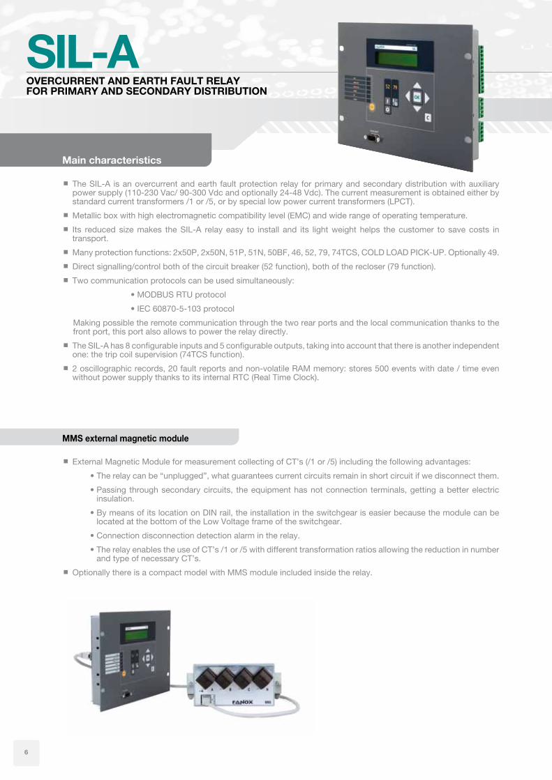
The SIL-A is an overcurrent and earth fault protection relay for primary and secondary distribution with auxiliary power supply (110-230 Vac/ 90-300 Vdc and optionally 24-48 Vdc). The current measurement is obtained either by standard current transformers /1 or /5, or by special low power current transformers (LPCT).
Metallic box with high electromagnetic compatibility level (EMC) and wide range of operating temperature.
Its reduced size makes the SIL-A relay easy to install and its light weight helps the customer to save costs in transport.
Direct signalling/control both of the circuit breaker (52 function), both of the recloser (79 function).
Two communication protocols can be used simultaneously:
•MODBUSRTUprotocol
•IEC60870-5-103protocol
Making possible the remote communication through the two rear ports and the local communication thanks to the front port, this port also allows to power the relay directly.
The SIL-A has 8 configurable inputs and 5 configurable outputs, taking into account that there is another independent one: the trip coil supervision (74TCS function).
2 oscillographic records, 20 fault reports and non-volatile RAM memory: stores 500 events with date / time even without power supply thanks to its internal RTC (Real Time Clock).
External Magnetic Module for measurement collecting of CT’s (/1 or /5) including the following advantages:
•BymeansofitslocationonDINrail,theinstallationintheswitchgeariseasierbecausethemodulecanbelocated at the bottom of the Low Voltage frame of the switchgear.
•Connectiondisconnectiondetectionalarmintherelay.
•TherelayenablestheuseofCT’s/1or/5withdifferenttransformationratiosallowingthereductioninnumberand type of necessary CT’s.
Optionally there is a compact model with MMS module included inside the relay.
Main characteristics
MMS external magnetic module
OVERCURRENT AND EARTH FAULT RELAYFOR PRIMARY AND SECONDARY DISTRIBUTION
6
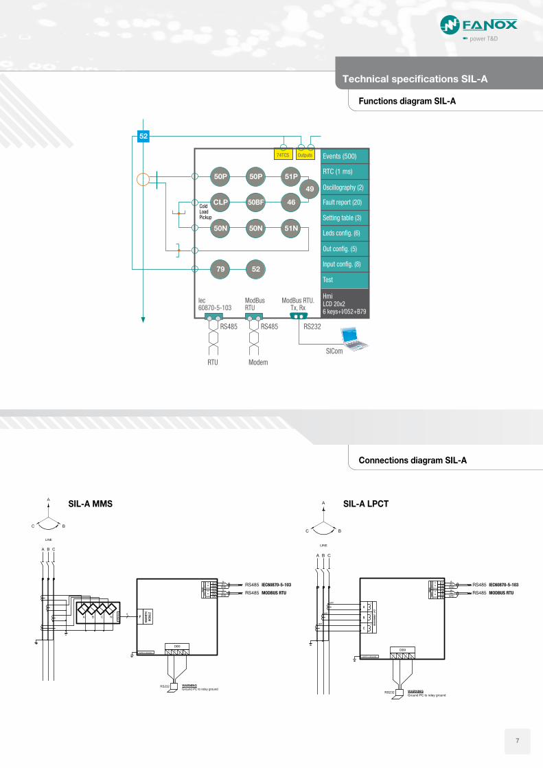
Functions diagram SIL-A
Connections diagram SIL-A
Technical specifications SIL-A
50P
50N
50BF
51P
Events (500)74TCS Outputs
RTC (1 ms)
Oscillography (2)
Setting table (3)
Fault report (20)
Leds config. (6)
Input config. (8)
Out config. (5)
Test
lec60870-5-103
ColdLoadPickup
ModBusRTU
RS232RS485
Modem
SICom
RTU
RS485
51N
46
49
50P
50N
CLP
5279
52
Hmi
6 keys+I/052+B79LCD 20x2
RS485 IEC60870-5-103RS485 IEC60870-5-103
RS485 MODBUS RTURS485 MODBUS RTU
SIL-A MMS SIL-A LPCT
ModBus RTU.Tx, Rx
7
Technical parameters SIL-A
Technical specifications
50P_150P_2
Function permission: Yes/no
Operating range: 0.10 to 30 xIn (pitch 0.01)
Operating time: 0.02 to 300 s (pitch 0.01 s)
Activation level 100%
Reset level 95%
Instant reset
50N_150N_2
Function permission: Yes/no
Operating range: 0.10 to 30 xIn (pitch 0.01)
Operating time: 0.02 to 300 s (pitch 0.01 s)
Activation level 100%
Reset level 95%
Instant reset
51P Function permission: Yes/no
Operating range: 0.10 to 7 xIn (pitch 0.01)
Curves IEC 60255-151 and ANSI
Operating time: Inverse curve, very inverse curve, extremely inverse curve. Definite time : 0.02 to 300 s (pitch 0.01 s)
Dial: 0.05 to 2.2
Curve activation level 120%
Curve reset level 100%
Definite time activation level 100%
Definite time reset level 95%
Instant reset
Timer precision: 5% or 30 ms (whichever is greater)
51N Function permission: Yes/no
Operating range: 0.10 to 7 xIn (pitch 0.01)
Curves IEC 60255-151 and ANSI
Operating time: Inverse curve, very inverse curve, extremely inverse curve. Definite time : 0.02 to 300 s (pitch 0.01 s)
Dial: 0.05 to 2.2
Curve activation level 120%
Curve reset level 100%
Definite time activation level 100%
Definite time reset level 95%
Instant reset
Timer accuracy: 5% or 30 ms (whichever is greater)
46 Function permission: Yes/no
Operating range: 0.01 to 1.00 xIn (pitch 0.01 s)
Operating time: 0.02 to 300 s (pitch 0.01 s)
Activation level: 100%
Reset level 95%
Instant reset
Circuit breaker monitoring
Circuit breaker status: start, open, closed, error, opening time, opening fault, closing time and closing fault.
Input 52a and/or input 52b
Open and close command
Alarm for maximum opening number: 1 to 10000
Alarm for accumulated amps: 0 to 10000 (kA²)
Maximum repeated openings: 1 to 10000
Time of maximum repeated openings: 1 to 300 min
50BF Function permission: Yes/no
Opening fault time: 0.02 to 300.0 s (pitch 0.01 s)
Open circuit breaker activation threshold: 8% In
Open circuit breaker reset threshold: 10% In
Function start: Equipment trip, activation of the opening fault input, circuit breaker open control activation.
79 Function Permission: yes/no
Hold permission: si/no
Number of reclosings: 1 a 5
Reclosing time 1, 2, 3, 4, 5 : 0.02 a 300.00 s (step 0.01 s)
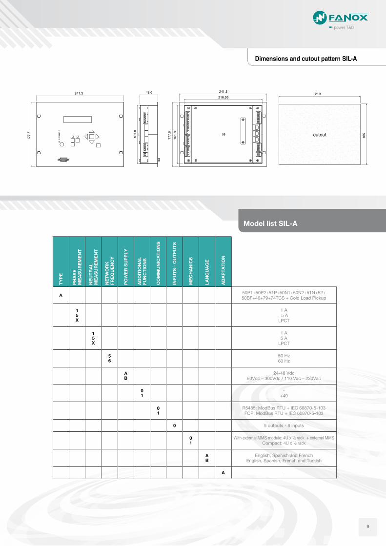
With external MMS module: 4U x ½ rack + external MMSCompact: 4U x ½ rack
AB
English, Spanish and FrenchEnglish, Spanish, French and Turkish
A -
Model list SIL-A
49.6
161.
8
241.3216.36
177.
8
177.
8
241.3219
165cutout
161.
8
9
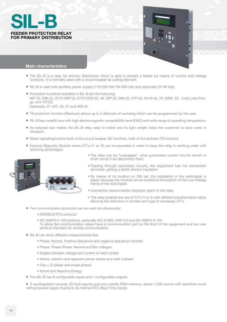
SIL-B
The SIL-B is a relay for primary distribution which is able to protect a feeder by means of current and voltage functions. It is normally used with a circuit breaker as cutting element.
SIL-B is used with auxiliary power supply (110-230 Vac/ 90-300 Vdc and optionally 24-48 Vdc).
Protection functions available in SIL-B are the following:50P (2), 50N (2), 67/51/50P (2), 67/51/50N (2), 46, 59P (2), 59N (2), 27P (2), 32/40 (4), 79, 50BF, 52, Cold Load Pick-up and 74TCS.Optionally: 81 U/O, 25, 37 and IRIG-B.
79 protection function (Recloser) allows up to 5 attempts of reclosing which can be programmed by the user.
SIL-B has metallic box with high electromagnetic compatibility level (EMC) and wide range of operating temperature.
Its reduced size makes the SIL-B relay easy to install and its light weight helps the customer to save costs in transport.
Direct signalling/control both of the circuit breaker (52 function), both of the recloser (79 function).
External Magnetic Module where CT’s (/1 or /5) are incorporated in order to keep the relay in working order with following advantages:
•The relaycanbe“unplugged”,whatguaranteescurrentcircuits remain inshort circuit if we disconnect them.
•Passing through secondary circuits, the equipment has not connectionterminals, getting a better electric insulation.
•Bymeans of its location onDIN rail, the installation in the switchgear iseasier because the module can be located at the bottom of the Low Voltage frame of the switchgear.
•Connectiondisconnectiondetectionalarmintherelay.
•TherelayenablestheuseofCT’s/1or/5withdifferenttransformationratiosallowing the reduction in number and type of necessary CT’s.
Two communication protocols can be used simultaneously:
•MODBUSRTUprotocol
•IEC60870-5-103protocol,optionallyIEC61850,DNP3.0andIEC60870-5-104To allow the communication relays have a communication port on the front of the equipment and two rear ports on the back for remote communication.
The SIL-B has 8 configurable inputs and 7 configurable outputs.
2 oscillographic records, 20 fault reports and non-volatile RAM memory: stores 1.000 events with date/time event without power supply thanks to its internal RTC (Real Time Clock).
Main characteristics
FEEDER PROTECTION RELAY FOR PRIMARY DISTRIBUTION
10
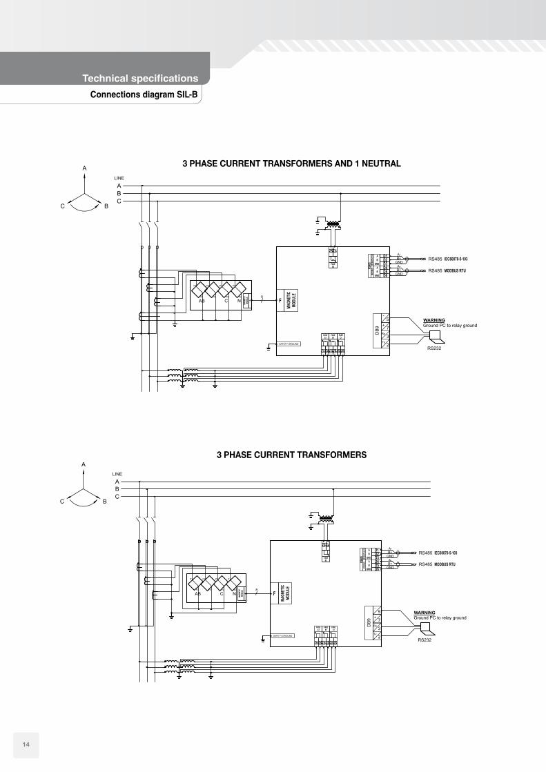
Functions diagram SIL-B
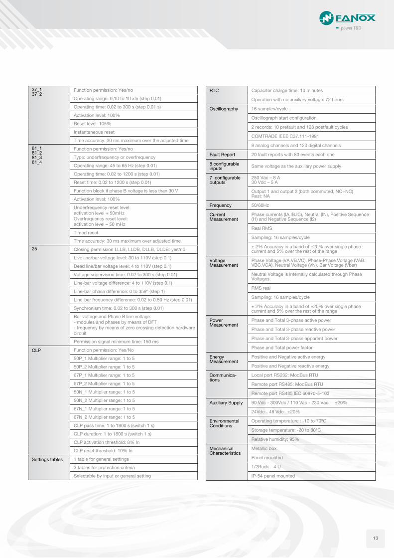
Technical specifications SIL-B
Events (1000)
RTC (1ms)
Oscillography (2)
Setting table (3)
Fault report (20)
Leds config. (6)
Out config. (7)
Test
Inputs config. (8)
74TCS
IEC 60870-5-103
67P ➔ 51P ➔ 50P
ModBus RTU
SILB
RS232
Modem
RTU
SICom
IRIG-B
RS485
RS485
32/40
CLP
50N 50N 67N
59N
27P59P
67N
59N
27P
67P*
59P
50BF 46 49 37
32/40 32/40 32/40
50P50P 67P* 67P*
52
Hmi
6 keys+I/052+B79LCD 20x2
79
81 U/O
52
25
ModBusRTU.
TxRx
11
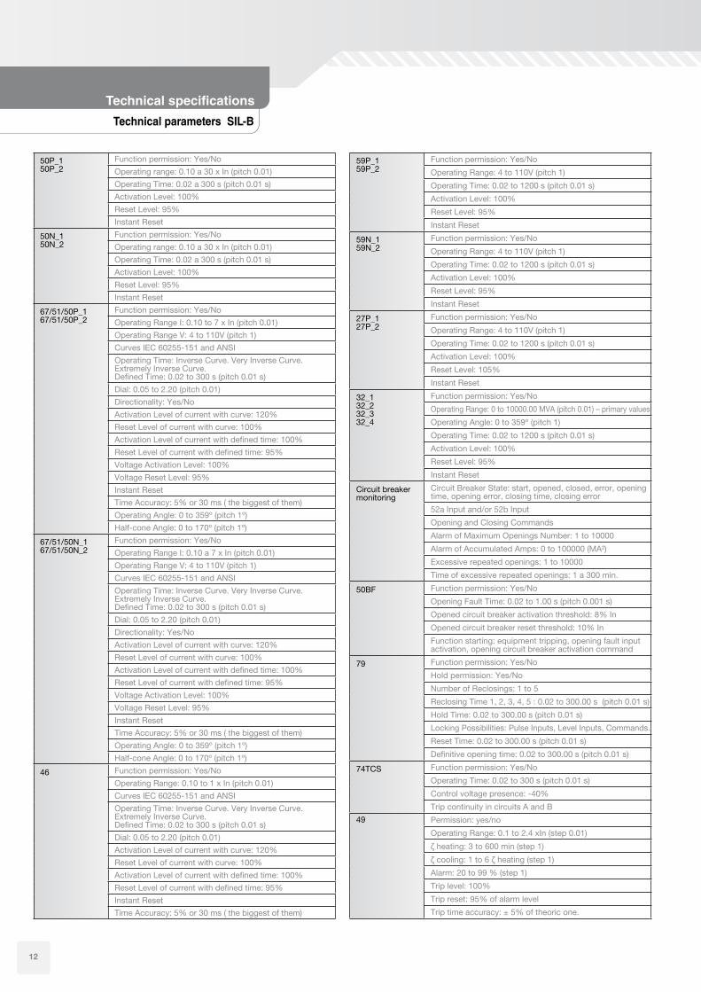
Technical parameters SIL-B
Technical specifications
50P_150P_2
Function permission: Yes/No
Operating range: 0.10 a 30 x In (pitch 0.01)
Operating Time: 0.02 a 300 s (pitch 0.01 s)
Activation Level: 100%
Reset Level: 95%
Instant Reset
50N_150N_2
Function permission: Yes/No
Operating range: 0.10 a 30 x In (pitch 0.01)
Operating Time: 0.02 a 300 s (pitch 0.01 s)
Activation Level: 100%
Reset Level: 95%
Instant Reset
67/51/50P_167/51/50P_2
Function permission: Yes/No
Operating Range I: 0.10 to 7 x In (pitch 0.01)
Operating Range V: 4 to 110V (pitch 1)
Curves IEC 60255-151 and ANSI
Operating Time: Inverse Curve. Very Inverse Curve. Extremely Inverse Curve. Defined Time: 0.02 to 300 s (pitch 0.01 s)
Dial: 0.05 to 2.20 (pitch 0.01)
Directionality: Yes/No
Activation Level of current with curve: 120%
Reset Level of current with curve: 100%
Activation Level of current with defined time: 100%
Reset Level of current with defined time: 95%
Voltage Activation Level: 100%
Voltage Reset Level: 95%
Instant Reset
Time Accuracy: 5% or 30 ms ( the biggest of them)
Operating Angle: 0 to 359º (pitch 1º)
Half-cone Angle: 0 to 170º (pitch 1º)
67/51/50N_167/51/50N_2
Function permission: Yes/No
Operating Range I: 0.10 a 7 x In (pitch 0.01)
Operating Range V: 4 to 110V (pitch 1)
Curves IEC 60255-151 and ANSI
Operating Time: Inverse Curve. Very Inverse Curve. Extremely Inverse Curve. Defined Time: 0.02 to 300 s (pitch 0.01 s)
Dial: 0.05 to 2.20 (pitch 0.01)
Directionality: Yes/No
Activation Level of current with curve: 120%
Reset Level of current with curve: 100%
Activation Level of current with defined time: 100%
Reset Level of current with defined time: 95%
Voltage Activation Level: 100%
Voltage Reset Level: 95%
Instant Reset
Time Accuracy: 5% or 30 ms ( the biggest of them)
Operating Angle: 0 to 359º (pitch 1º)
Half-cone Angle: 0 to 170º (pitch 1º)
46 Function permission: Yes/No
Operating Range: 0.10 to 1 x In (pitch 0.01)
Curves IEC 60255-151 and ANSI
Operating Time: Inverse Curve. Very Inverse Curve. Extremely Inverse Curve. Defined Time: 0.02 to 300 s (pitch 0.01 s)
Dial: 0.05 to 2.20 (pitch 0.01)
Activation Level of current with curve: 120%
Reset Level of current with curve: 100%
Activation Level of current with defined time: 100%
With external MMS module: 4U x ½ rack + external MMSCompact: 4U x ½ rack
AB
English, Spanish and FrenchEnglish, Spanish, French and Turkish
A -
Model list SIL-B
161.
8
62
177.
8
161.
8
241.3
216.36
177.
8
241.3 219
165cutout
15
COMMON ELEMENTS SIL-A & SIL-B
HMIThe HMI consists of:
•A2x20LCDscreenwithalphanumericcharactersthatallow the equipment parameters to be set (adjusted) and monitored (measurements, statuses, events).
•Amembrane keyboardwith six keys that allow youto navigate the menus and access information of interest. A seventh button - “RESET”, allows you to reset the events log. For security reasons, an access code is needed to modify the settings.
•Thereisaspecifickeyforthefunction79aswellasaconcrete LED, which allow commanding the recloser, by means of blocking, releasing and showing its state.
•In the sameway, there are other two specific keysfor the function 52 as well as a concrete LED, which allow commanding the circuit breaker, by means of opening, closing and showing its state.
•Additionally,therearesixLED’sontheleftoftheHMIthat can be programmable by the user.
Self-diagnosisDiagnostic algorithms to generate the corresponding events are executed on starting up the equipment and all the time the relay is operating.
Test Menu
This allows you to use the HMI to verify correct operation of the LEDs and the output contacts.
On SIL-A, it is possible to activate the 5 outputs and the 8 LEDs.
On SIL-B, it is possible to activate the 7 outputs and the 8 LEDs.
EventsEvents are recorded and ordered chronologically (up to 1.000), allowing you to analyse what has happened with the installation over time (start-ups, tripping power supplies, etc.). They are recorded chronologically to the nearest millisecond in real time, thanks to the Real Time Clock (RTC).
16
CommunicationsThe relays have a communication local port on the front of the equipment and two rear ports on the back for remote communication.
The SICom programme with Windows® 2000/XP and 7 uses a graphic user interface to allow you to access all equipment information, modify the settings and save events.
The programme can be used locally by using the front port or remotely by using the rear RS485 ModBus port.
There are 4 levels of access with user-definable codes.
elements
17
18
CUSTOMIZED PRODUCTS AND BRANDLABELING
Every day an increasing number of companies are considering the option of outsourcing their design and product development.
Fanox is the perfect technology partner to carry out these activities. Our R & D department is prepared to operate as an integral part of our clients business adapting to their needs y developing custom designs.
Fanox is a leader in the customization of products for reputable manufacturers, and we offer added value at a very competitive price. Fanox provides additional performance characteristics to the equipment thanks to continuous improvement of electronics spear heading a rapidly moving technology sector.
Dual and Self powered
Signalling with magnetic bistable indicators
High electromagnetic compatibility
Events recorder and specific test menu
power T&D
Protection relays for secondary distribution
The SIA relays family, SIA-C, SIA-A and SIA-D, are designed to protect the secondary transformation and distribution centres of electrical grids. The protection features include protection against instantaneous and inverse time overcurrent (for the phases and the neutral) as well as an external trip support (temperature, pressure, etc.) depending on the model.
New
FANOX is involved in all levels of electrical distribution, both primary and secondary, and has a great deal of experience in designing and producing made to measure equipment for manufacturers of primary substations with relation to protection control, measurement and communication, and is an important reference within this field.
Fanox reserves the right to modify technical specification of products contained within this catalogue without previous notice.
01/2012/ Rev. 04
Parque Tecnológico de BizkaiaAstondo bidea, Edif. 604