October 2017, Volume 4, Issue 10 JETIR (ISSN-2349-5162) JETIR1710061 Journal of Emerging Technologies and Innovative Research (JETIR) www.jetir.org 371 Reduction of Torque Ripple in Brushless DC Drive by Using Capacitor Switching with fuzzy controller M Bhargava Kumar 1 , C Prashanth Sai 2 , U Padmaja 3 1 PG Scholar, Dept.of Electrical Engineering, JNTUA College of Engineering, Anantapur, Andhra Pradesh, India. 2 Lecturer, Dept.of Electrical Engineering, JNTUA College of Engineering, Anantapur, Andhra Pradesh, India. 3 PG Scholar, Dept.of Electrical Engineering, JNTUA College of Engineering, Anantapur, Andhra Pradesh, India. ABSTRACT Brushless DC (BLDC) motors have been gaining attention from different Industrial and domestic appliance manufacturers, because of their high power density, high efficiency, low cost and easy maintenance. Brushless DC motors are having a major problem with ripple in torque. The brushless DC drive without capacitor has more ripple to reduce that ripple by using a torque ripple compensation technique based on an actively controlled small capacitor is proposed for brushless dc motor. In proposed compensation technique, capacitor is used in uncontrollable region for the brushless dc motor drive, which is discontinuous current region nothing but uncontrollable region. The proposed brushless dc motor drive of small capacitor is charging in controllable region through diode switch. The small capacitor is discharge in uncontrollable region through controlled switch. This paper presents a three-phase BLDC motor with low cost drive to be driven without DC link capacitor. The proposed technique uses an electronic commutation and operates the machine exclusive of the intermediate DC link capacitor. The designing of Brushless DC motor drive system along with PI controller and fuzzy controller to reduce torque ripple by using MATLAB / SIMULINK and simulated results indicate that the total harmonic distortion of the machine is better than existing techniques. Keywords: Brushless DC drive, Torque ripple compensation, uncontrollable region, controllable region, and harmonics. I. INTRODUCTION Permanent Magnet Synchronous (PMS) motors and Brushless DC (BLDC) motors are becoming more useful in industrial applications and home appliance because of their high reliability, efficiency and low cost and maintenance compared to other motors. BLDC and PMS motors are now designed with high power densities, these causes the increasing their popularity in applications such as airspace applications and mobile coolers. Therefore, BLDC motors have becoming more popular for industrial applications where efficiency, compact and cost effective factors are considered. PMS motors needs continuous rotor position information for their operation and a significant computational time is required to improve the motor Performance by controlling the rotor. By using rotor position, BLDC motors are commutated electronically and the rotor position information can be obtained by using position sensors. Hall Effect sensors or back EMF sensing technique is used to obtain the rotor position of BLDC motor for every 60 electrical degrees. The Brushless DC motor drive consists of a diode bridge rectifier and a large electrolytic capacitor with a converter fed rotor for rotor position information. The Brushless DC motor drive with fixed capacitor circuit as shown in fig.1. The main function includes, bus voltage stabilization, ripple current conduction due to switching events, etc. The intermediate DC link capacitor used in indirect conversion topologies, requires a large space for its installation, which results in increasing its weight and occupying place.
Transcript
October 2017, Volume 4, Issue 10 JETIR (ISSN-2349-5162)
JETIR1710061 Journal of Emerging Technologies and Innovative Research (JETIR) www.jetir.org 371
Reduction of Torque Ripple in Brushless DC Drive by Using Capacitor Switching with fuzzy
controller
M Bhargava Kumar 1, C Prashanth Sai 2, U Padmaja 3
1 PG Scholar, Dept.of Electrical Engineering, JNTUA College of Engineering, Anantapur, Andhra Pradesh, India. 2 Lecturer, Dept.of Electrical Engineering, JNTUA College of Engineering, Anantapur, Andhra Pradesh, India.
3 PG Scholar, Dept.of Electrical Engineering, JNTUA College of Engineering, Anantapur, Andhra Pradesh, India.
ABSTRACT
Brushless DC (BLDC) motors have been gaining attention from different Industrial and domestic appliance
manufacturers, because of their high power density, high efficiency, low cost and easy maintenance. Brushless DC motors
are having a major problem with ripple in torque. The brushless DC drive without capacitor has more ripple to reduce that
ripple by using a torque ripple compensation technique based on an actively controlled small capacitor is proposed for
brushless dc motor. In proposed compensation technique, capacitor is used in uncontrollable region for the brushless dc
motor drive, which is discontinuous current region nothing but uncontrollable region. The proposed brushless dc motor
drive of small capacitor is charging in controllable region through diode switch. The small capacitor is discharge in
uncontrollable region through controlled switch. This paper presents a three-phase BLDC motor with low cost drive to be
driven without DC link capacitor. The proposed technique uses an electronic commutation and operates the machine
exclusive of the intermediate DC link capacitor. The designing of Brushless DC motor drive system along with PI controller
and fuzzy controller to reduce torque ripple by using MATLAB / SIMULINK and simulated results indicate that the total
harmonic distortion of the machine is better than existing techniques.
Keywords: Brushless DC drive, Torque ripple compensation, uncontrollable region, controllable region, and harmonics.
I. INTRODUCTION
Permanent Magnet Synchronous (PMS) motors
and Brushless DC (BLDC) motors are becoming more
useful in industrial applications and home appliance
because of their high reliability, efficiency and low cost
and maintenance compared to other motors. BLDC and
PMS motors are now designed with high power densities,
these causes the increasing their popularity in applications
such as airspace applications and mobile coolers.
Therefore, BLDC motors have becoming more popular for
industrial applications where efficiency, compact and cost
effective factors are considered.
PMS motors needs continuous rotor position
information for their operation and a significant
computational time is required to improve the motor
Performance by controlling the rotor. By using
rotor position, BLDC motors are commutated
electronically and the rotor position information can be
obtained by using position sensors. Hall Effect sensors or
back EMF sensing technique is used to obtain the rotor
position of BLDC motor for every 60 electrical degrees.
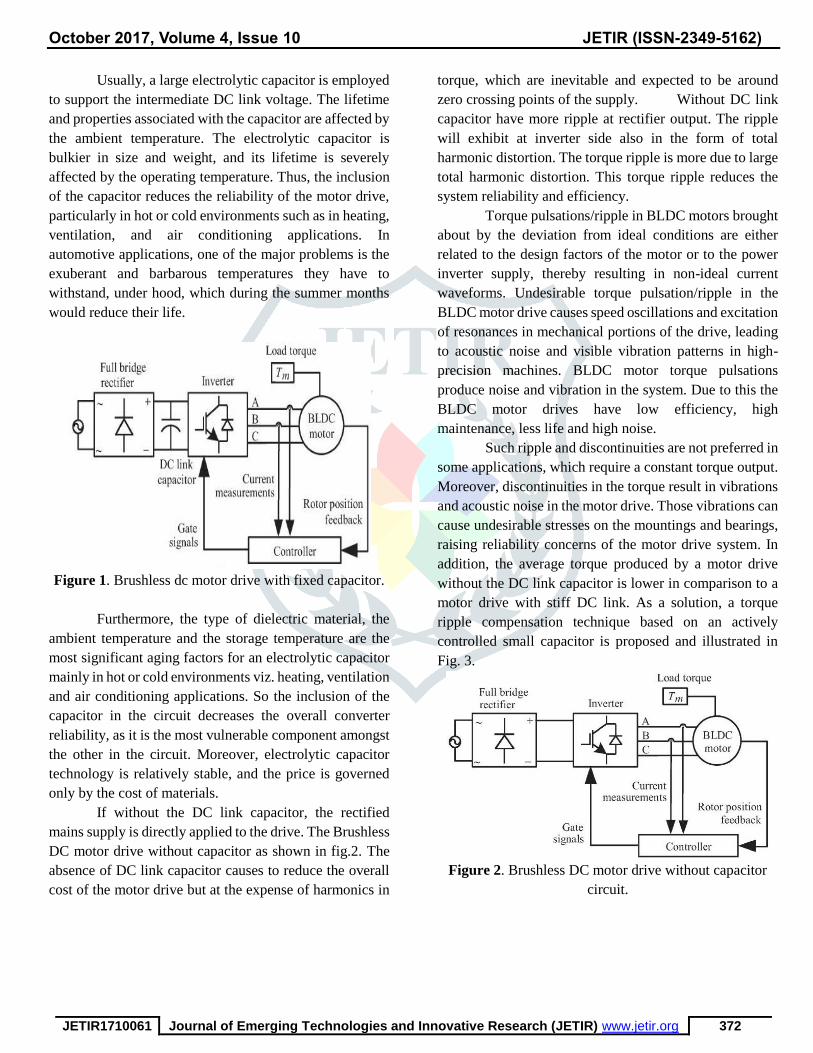
The Brushless DC motor drive consists of a diode
bridge rectifier and a large electrolytic capacitor with a
converter fed rotor for rotor position information. The
Brushless DC motor drive with fixed capacitor circuit as
shown in fig.1. The main function includes, bus voltage
stabilization, ripple current conduction due to switching
events, etc. The intermediate DC link capacitor used in
indirect conversion topologies, requires a large space for
its installation, which results in increasing its weight and