282
U 408.$ fM ^ Ü'íi eítíf-úñeg Referencö DEPARTMENT OF THE ARMY FIELD MANUAL ARTILLERY ‘i SURVEY ire« 9» nTfr. FM 6-2 HEADQUARTERS, DEPARTMENT 0 AUGUST 1961 THE ARMY

U 408.$
fM ^
Ü'íi eítíf-úñeg
Referencö
DEPARTMENT OF THE ARMY FIELD MANUAL
ARTILLERY
‘i
SURVEY
ire« 9»
nTfr.
FM 6-2
HEADQUARTERS, DEPARTMENT 0
AUGUST 1961
THE ARMY


*FM 6-2
FIELD MANUAL'] HEADQUARTERS, L DEPARTMENT OF THE ARMY
No. 6-2 J WASHINGTON 25, D.C., 7 August 1961
ARTILLERY SURVEY
Paragraphs Page
PART ONE. GENERAL
CHAPTER 1. INTRODUCTION 1-7 4
2. ARTILLERY SURVEY PURPOSE AND RESPONSIBILITIES 8-14 5
PART TWO. SURVEYING EQUIPMENT AND PROCEDURES
CHAPTER 3. SURVEY EQUIPMENT
Section I. General 15-18 8
II. Discussion of survey accessories 19-26 9
CHAPTER 4. TAPES AND TAPING
Section I. General 27—29 10
II. Taping procedures and techniques 30-44 10
III. Accuracy and errors 45—49 17
CHAPTER 5. AIMING CIRCLE M2
Section I. General 50—52 18
II. Use of aiming circle 53-64 23
III. Care and maintenance 65-67 28
CHAPTER 6. TRANSIT
Section I. General 68—72 30
II. Use of transit 73—87 34
CHAPTER 7. THEODOLITE, WILD T16
Section I. General 88—95 45
II. Use of theodolite 96-98 48
III. Care and maintenance 99-107 51
CHAPTER 8. THEODOLITE, WILD T2, MIL-GRADUATED
Section I. General 108-114 54
II. Use of theodolite 115-121 56
III. Care and maintenance 122-131 61
IV. Sexagesimal theodolite Wild T2 132—137 65
CHAPTER 9. TELLUROMETER MRA 1/CW/MV
Section I. General 138,139 67
II. Principles of operation 140-144 70
III. Tellurometer operations and computations 145-161 72
IV. Tellurometer maintenance 162-165 84
CHAPTER 10. TARGET SET, SURVEYING
Section I. General 166-170 89
II. Use and care of the target 171-174 89
This manual supersedes TM 6-200, 13 June 1958.
1

CHAPTER 11. Section I.
II.
CHAPTER 12.
Section I.
II.
III.
CHAPTER 13.
PART THREE.
CHAPTER 14. Section I.
II.
III.
IV.
CHAPTER 15. Section I.
II.
III.
IV.
V.
VI.
' VII.
PART FOUR.
CHAPTER 16.
Section I.
II.
III.
IV.
CHAPTER 17.
18.
19. Section I.
II.
III.
CHAPTER 20. Section I.
II.
III.
IV.
PART FIVE
CHAPTER 21.
Section I.
II.
III.
Paragraphs
ARTILLERY GYRO AZIMUTH SURVEYING INSTRUMENT
General 175,176
Use, care, and maintenance of artillery gyro azimuth surveying instrument 177-181
ALTIMETER
General 182-186
Use of the altimeter 187-193
Procedures and computations 194-196
FIELD NOTES 197-206
SURVEY METHODS AND COMPUTATIONS
TRAVERSE
Procedures
Computations
Traverse adjustment
Location of traverse errors
TRIANGULATION
General
Single triangle and single chain
Quadrilaterals
Central point figures
Resection
Intersection
Trilatération
207-216
217-228
229-233
234-236
237-239
240-249
250-256
257, 258
259-263
264-267
268-270
ARTILLERY SURVEY OPERATIONS AND PLANNING
FIELD ARTILLERY BATTALION AND BATTERY SURVEY OPERATIONS
General 271-282
Position area survey 283-287
Connection survey 288, 289
Target area survey 290-294
DIVISION ARTILLERY SURVEY 295-299
CORPS ARTILLERY SURVEY 300-315
OTHER ARTILLERY UNIT SURVEYS
Field artillery group surveys 316, 317
Field artillery missile command surveys 318, 319
Air defense artillery surveys 320-326
SURVEY PLANNING
General 327-338
Steps in survey planning 339-343
The survey plan 344-347
Standing operating procedure 348,349
DETERMINATION OF AZIMUTH BY ASTRONOMIC OBSERVATIONS
BASIC ASTRONOMY
General 350-361
Astronomic triangle 362-366
Star identification 367-371
Page
91
92
95
98
104
110
127
131
142
145
147
148
153
159
162
165
165
167 170 173 173
177
179
188 188 189
192 194 195 195
197 204
207
2

Paragraphs Page
CHAPTER 22. THE ALTITUDE METHOD
Section I. General 372-375 212
II. Determining field data 376-389 213
III. Computations 390-392 217
CHAPTER 23. HOUR-ANGLE METHOD
Section I. General 393,394 223
II. Determining field data 395-403 223
III. Computations 404—407 224
CHAPTER 24. AZIMUTH BY SIMULTANEOUS OBSERVATIONS 408-411 230
25. COMPARISON OF METHODS 412-418 234
PART SIX. CONVERTING SURVEY CONTROL, CONVERSION OF COORDINATES, AND TRANSFORMATION
CHAPTER 26. CONVERTING SURVEY CONTROL 419-424 238
27. CONVERSION OF COORDINATES 425-430 243
28. TRANSFORMATION 431-437 248
APPENDIX I. REFERENCES 253
II. SURVEY TECHNIQUES 256
III. DUTIES OF SURVEY PERSONNEL 259
INDEX 261
3

PART ONE
GENERAL
CHAPTER 1
INTRODUCTION
1. Purpose a. This manual is a guide for commanders,
survey officers, and personnel engaged in the conduct of artillery surveys. It provides a basis for instruction, guidance, and reference in surveying principles and procedures, and in the care and operation of surveying instru- ments. Procedures covering all situations can- not be prescribed; therefore, the instructions contained herein should be used as a guide in developing the application of suitable tech- niques. The material presented herein is ap- plicable without modification to both nuclear and nonnuclear warfare.
b. Users of this manual are encouraged to submit recommended changes or comments to improve the manual. Comments should be keyed to the specific page, paragraph, and line of the text in which the change is recom- mended. Reasons should be provided for each comment to insure understanding and complete evaluation. Comments should be forwarded direct to the Commandant, U.S. Army Artillery and Missile School, Fort Sill, Oklahoma.
2. Scope This manual expounds the survey personnel
and equipment available to artillery units, the measurement of angles and distances, and the determination of relative locations on a rec- tangular grid system.
3. References Publications used as references for the
manual and those offering further technical information are listed in appendix I.
4. Definitions Technical terms not included in AR 320-5
are defined the first time they are used in this manual.
5. Fundamental Operations of Survey Survey results are obtained from the follow-
ing: a. Planning. A thorough plan which gives
full consideration to the factors affecting survey and conforms to basic essentials contributes to a successful accomplishment of the survey.
b. Fieldwork. Survey fieldwork consists of— (1) Measuring distances. (2) Measuring horizontal and/or vertical
angles. (3) Recording all pertinent data.
c. Computations. The computations are per- formed simultaneously with the fieldwork. The known data and the fieldwork data are com- bined to produce the location and/or height of a point and/or the direction of a certain line.
6. Accuracy Three minimum orders of accuracy are pre-
scribed for artillery surveys: artillery fourth- order survey, 1:3,000; artillery fifth-order survey, 1:1,000; and artillery 1:500; e.g., an accuracy of 1:3,000 means that for each 3,000 units of distance surveyed, the error cannot exceed 1 unit. The order or accuracy required depends on the intended use of the survey data.
7. Survey Specifications and Techniques Specifications and techniques required to
achieve each artillery order of survey accuracy set forth in paragraph 6 are listed in appendix II.
4

CHAPTER 2
ARTILLERY SURVEY PURPOSE AND RESPONSIBILITIES
8. Purpose of Artillery Survey Artillery survey operations provide a com-
mon grid which will permit the massing of fires, delivery of surprise observed fires, de- livery of effective unobserved fires, and trans- mission of target data from one unit to another. The establishment of a common grid is a com- mand responsibility.
9. Responsibilities of the Corps of Engineers
a. The survey responsibilities of the Corps of Engineers are described in AR 117-5 and TM 5-231. In regard to artillery survey, engi- neer responsibilities include—
(1) The supply of maps. (2) The supply of trig lists and other sur-
vey control data. (3) Extension of ground control as de-
scribed in b and c below. b. When existing survey control is not avail-
able, the normal procedure is for the survey company of the engineer base topographic battalion to extend control to the rear boundary of army areas; the survey platoon of the engi- neer topographic battalion (army) to extend control to the rear boundaries of subordinate corps; and the survey platoon of the engineer topographic company to extend control as di- rected by the corps commander.
c. The survey element organic to the engi- neer combat battalion, missile command (medium), has the responsibility of providing survey control point throughout the width of the missile command area for use by the survey platoons of the target acquisition battalion, missile command (medium).
10. General Responsibilities of Artillery Units
Each artillery commander is responsible for seeing that required survey control is furnished to subordinate units as soon as possible.
11. Battalion (Separate Battery) Survey Responsibilities
The battalion (separate battery) survey offi- cer plans, coordinates, and supervises battalion (battery) survey operations. Battalion (sepa- rate battery) survey personnel perform the survey operations necessary to establish—
a. The grid coordinates and the height of— (1) The battery center for each light,
medium, and heavy artillery battery. (2) The position of each weapon for very
heavy artillery. (3) The battery center for mortar battery
or mortar platoon in applicable or- ganization.
(4) The position of each launcher and, when required, guidance radar and orienting station for artillery missile battalions (separate battery).
b. An orienting line for each weapon posi- tion and missile guidance element when re- quired and to compute the orienting angle for each weapon position.
c. The grid coordinates, the height, and a line of known direction for radar positions when so directed.
d. The grid coordinates, the height, and a line of known direction for each target area base observation post (OP) (always required for direct support artillery; as directed for other artillery).
e. The grid coordinates and the height of critical points in the target area ; i.e., registra- tion points, restitution points (always required
5

for direct support artillery; as directed for other artillery).
/. The grid coordinates, the height, and a line of known direction for additional points as directed by the battalion commander.
12. Division Artillery Survey Responsibility The division artillery survey officer coordi-
nates and supervises the survey operations of subordinate echelons. He establishes the divi- sion artillery survey information center (ex- cept for airborne division artillery). The divi- sion artillery survey party performs the survey operations necessary to establish—
a. The grid coordinates, the height, and a line of known direction for each—
(1) Survey control point (SCP) for each organic or attached field artillery battalion and separate battery.
(2) Division artillery observation post (when required).
(3) Attached searchlight platoon survey control point in areas for which maps are not available.
(4) Meteorological orienting station in areas for which large-scale maps are not available.
(5) Additional point designated by the division artillery commander; e.g., a survey control point for a tank unit assigned an indirect fire mission.
b. The grid coordinates and heights of points in the target area as directed by the division artillery commander.
c. Declination stations as needed. d. A line of known direction for meteorol-
ogical orienting stations in areas for which large-scale maps are available (position can be inspected to required accuracy).
13. Field Artillery Target Acquisition Battalion Survey Responsibility
The field artillery target acquisition battalion coordinates the survey operations of lower echelons. To facilitate this coordination, the battalion establishes a corps survey informa- tion center (SIC), where records are main- tained of all fourth order and higher survey control points existing in the corps area. The survey platoons within the battalion perform the survey operations necessary to establish—
a. The grid coordinates, the height, and a line of known direction for each—
(1) Division artillery survey control point.
(2) Corps artillery battalion (separate battery) survey control point.
(3) Flash ranging observation post of the target acquisition battalion.
(4) Counterbattery radar set of the target acquisition battalion.
(5) Survey control point required for the searchlight battery (platoon) in areas for which maps are not available.
(6) Additional points designated by the corps artillery commander; e.g., Air Force radio and radar installations located in the corps area, including target director posts.
(7) Meteorological orienting station in areas for which large-scale maps are not available.
(8) Drone platoon in areas for which maps are not available.
b. The ground location of each sound rang- ing microphone of the target acquisition batta- lion.
c. Declination stations as needed. d. A line of known direction for meteorol-
ogical orienting stations in areas for which large-scale maps are available (position can be inspected to required accuracy).
14. Air Defense Artillery Survey The survey operations performed by an air
defense artillery (ADA) unit are determined by the mission assigned to the unit.
a. The purpose of the survey operations of air defense artillery units assigned a ground support field artillery (FA) mission is to pro- vide survey control that will permit the mass- ing of fire, delivery of surprise observed fires, and delivery of effective unobserved fires. The survey operations performed are the same as those performed by a field artillery missile bat- talion.
b. The purpose of the survey operations of air defense artillery units assigned an air de- fense mission is to provide survey control that will permit the exchange of target information and that will insure the delivery of air defense fires outside the limits of restricted areas.
6

c. When suitable maps are available and there are no restricted areas, personnel and ADA gun battalions and ADA automatic weap- ons (AW) battalions with electronic fire con- trol equipment must perform the survey op- erations necessary to establish the slant range from the track radar to the radar range- calibrating point for each battery.
d. When suitable maps are not available and/ or when there are restricted areas, personnel of the ADA gun battalions perform the survey operations necessary to establish—
(1) The grid coordinates, the heights, and the azimuth to an orienting point for the battalion surveillance radar and the track radar of each battery.
(2) The slant range from each track radar to its radar range-calibrating point.
(3) When directed, the distance from each track radar to the orienting point.
e. When suitable maps are not available and/ or when there are restricted areas, personnel of ADA AW battalions (batteries) with electronic fire control equipment and personnel of 75-mm light ADA battalions (batteries) perform the survey operations necessary to establish—
(1) The grid coordinates, the height, and
the azimuth to an orienting point for each weapon.
(2) The slant range from each weapon to its radar range-calibrating point.
f. When suitable maps are not available, per- sonnel of ADA AW battalions without elec- tronic fire control equipment perform no survey operations except when there are restricted areas. When there are restricted areas, they perform the survey operations necessary to establish the grid coordinates, the height, and the azimuth to an azimuth mark for each fire unit.
g. The grid coordinates and the azimuth to an orienting point for the track radars of ADA missile batteries in an air defense role normal- ly will be determined by engineer survey op- erations. However, personnel of semimobile ADA missile batteries may be required to determine these data by performing limited survey operations.
h. Personnel of ADA missile batteries as- signed a ground support FA mission perform survey operations to determine the grid co- ordinates and height of track radars and an azimuth to an orienting point for each track radar. For further discussion of survey opera- tions for air defense artillery unit refer to chapter 19.
7

PART TWO
SURVEYING EQUIPMENT AND PROCEDURES
CHAPTER 3
SURVEY EQUIPMENT
Section I. GENERAL
15. General Survey equipment consists of instruments
and accessories necessary to perform a survey. Survey instruments include those items of equipment with which measurements are made. Survey accessories include those items of equip- ment which assist in making measurements and in recording, computing, and plotting survey data.
16. Survey Instruments a. The instruments employed in artillery
surveying are— (1) Steel tape. (2) Aiming circle. (3) Transit. (4) Theodolite (FA units only). (5) Altimeter (FA units only). (6) Target set, surveying. (7) Tellurometer. (8) Surveying Instrument Azimuth Gyro
Artillery. b. The survey instruments in a above are dis-
cussed in chapters 4 through 12.
17. Survey Accessories The accessories employed in artillery survey-
ing are— a. Taping equipment which includes—
(1) Plumb bobs. (2) Steel arrows (taping pins). (3) Tension handles (certain FA units
only).
(4) Clamping handles (certain FA units only).
(5) Hand levels (certain FA units only). b. Station marking equipment which in-
cludes— (1) Ranging poles. (2) Ranging pole tripod (certain FA units
only). (3) Levels for level rod (FA units only). (4) Target cloth. (5) Hatchets. (6) Wooden and/or steel stakes.
c. Recording and computing equipment which includes—
(1) Notebooks. (2) Department of the Army forms. (3) Pencils. (4) Logarithmic and mathematical tables
(TM 6-230 and/or Vega tables). (5) Army Ephemeris (TM 6-300-61).
d. Numerous items of miscellaneous equip- ment which include—
(1) Star identifiers (certain FA units only).
(2) Computing machines (certain FA units only).
(3) Military slide rules (FA units only).
18. Surveying Equipments Sets a. Field artillery units are issued angle-
measuring instruments as separate items. Field artillery units authorized altimeters and/or computing machines are issued those items
8

separately. All other items of survey equip- ment, with the exception of forms and tech- nical manuals, are issued to field artillery units in two surveying equipment sets. These sets are—
(1) Artillery survey set, fourth order.
(2) Artillery survey set, third order. b. Artillery survey set, fourth order was de-
signed for use by units performing survey with the aiming circle; artillery survey set, third order was designed for use by units using the theodolite or transit.
Section li. DISCUSSION OF SURVEY ACCESSORIES
19. General a. Logarithmic tables are discussed in TM
6-230. b. The military slide rule is discussed in TM
6-240. c. Survey computation forms are explained
in conjunction with the method of survey in which they are employed within this manual.
d. Other accessories which are used fre- quently are discussed in paragraphs 20 through 26.
20. Plumb Bob The plumb bob is used in artillery surveying
as a taping accessory and as an angle measur- ing instrument accessory. Most plumb bobs used consist of a body and removable cap made of brass and a replaceable point made of steel. The plumb bob used with the M2 aiming circle is of one-piece steel construction.
21. Taping Pins
Steel arrows, called taping pins, have a ring on one end and a sharp point on the other. These pins are issued in sets of 11. They are used to mark, temporarily, the positions of the ends of the tape on the ground as tape lengths are measured.
22. Tension Handle
The tension handle is used in training survey personnel to apply the correct amount of ten- sion to a steel tape. This handle is a spring balance, graduated in pounds from 0 to 30. With prolonged use the spring of the tension handle will gradually stretch, causing errone-
ous readings. It must therefore be tested oc- casionally with a weight of known value.
23. Clamping Handle The clamping handle is used to hold and
apply tension to the tape when a partial tape length is being measured.
24. Hand Level The hand level is used to measure approxi-
mate differences in elevation. It is used in artillery survey to train taping personnel to recognize when the tape is held horizontal. This instrument consists of a metal sighting tube with plain glass covers at the ends and a level vial mounted on the tube. It is usually hand held in front of the eye. The landscape, level bubble, and index line can be seen in the tube.
25. Ranging Pole The ranging pole is constructed of tubular
steel. It consists of two interlocking sections, one of which is pointed. The length of the as- sembled pole is 6 feet, 6 inches. The pole is painted in six 1-foot sections which are alter- nately red and white. For storage, the pole is disassembled and placed in a canvas case.
26. Ranging Pole Tripod The ranging pole tripod is used for holding
a ranging pole over a survey station. In use, the tripod is set up so that the head of the tripod is approximately 3 inches horizontally from the survey point. The' ranging pole is then placed in the collar of the adjustable arm. The pole is then made vertical by using the level for the level rod.
9

CHAPTER 4
TAPES AND TAPING
Section I.
27. Tapes and Accessories
a. Field artillery survey personnel are equipped with 30-meter steel tapes for making linear measurements (taping). These tapes are graduated on one side only, in meters, deci- meters (0.1 meter), and centimeters (0.01 meter) throughout, with the first decimeter graduated in millimeters (0.001 meter). There is a blank space at each end of the tape. A reel and two leather thongs are furnished with each tape.
b. In addition to a tape, each taping team should be equipped with 2 plumb bobs, 1 plumb bob and arrow holder, 1 clamping handle, 1 set of 11 arrows (taping pins), 1 hand level, 1 tension handle, 2 leather thongs, 2 notebooks, and 2 pencils (fig. 1).
28. Care of Steel Tapes
a. Steel tapes are accurate surveying instru- ments and must be handled with care. Al- though steel tapes are of durable construction, they can be easily damaged through improper care and use.
b. In use, the tape should be completely re- moved from its reel and kept straight to pre- vent its being kinked or broken. The tape
GENERAL
should never be pulled around an object that will put a sharp turn in the tape. Do not jerk the tape, step on it, or allow vehicles to run over it. If there is a loop in the tape, it may be kinked or broken when tension is applied. Before applying tension, the tapemen should see that the tape is not looped.
c. After use, the tape should be wiped clean and dry and then oiled lightly. The tape is oiled by running it through an oily rag as it is being reeled in. The tape should be loosely wound on its reel when not in use. In winding the tape on the reel, insert the end of the tape with the 30 meter graduations into the reel and wind the tape in such a manner as to cause the num- bers to be wound facing the axle of the reel.
29. Repair of Broken Tape a. A sheet metal sleeve coated on the inside
with solder and flux is fitted over the broken ends of the tape and hammered down tightly. By applying heat, even from an ordinary match, the tape is securely fastened together.
b. The repaired section of the tape must be checked with another section of the tape to in- sure that the ends of the tape were placed to- gether and that a true measurement can still be made.
Section II. TAPING PROCEDURES AND TECHNIQUES
30. Horizontal Taping, General a. The method of taping used in artillery
surveys is known as horizontal taping. In this method, all measurements are made with the tape held horizontally. The point from which the distance is to be measured is the rear sta- tion. The point to which the distance is to be
measured is the forward station. The distance between stations is usually several times great- er than a full tape length. The taping team, starting at the rear station, determines the distance by measuring successive full tape lengths until the distance remaining is a par- tial tape length. This length is then measured.
10

&
i**»«
II
i©0';
Figure 1. Taping equipment.
The distance between stations is determined by adding the product of the number of tape lengths and the length of the tape to the partial tape length. Each measurement is made with the tape held horizontally between the rear and forward stations.
h. A taping team consists of two men—a front tapeman and a rear tapeman. The rear tapeman commands the taping team. The rear tapeman determines and reports the distance measurement; the front tapeman independent- ly checks the distance measurement. Additional personnel are required for taping at night.
31. Measuring First Full Tape Length To measure the first full tape length— a. The front tapeman gives one taping pin
to the rear tapeman, keeping 10 pins in his
possession. The pin given to the rear tapeman represents the first full tape length. The front tapeman moves toward the forward station with the zero end of the tape.
h. As the end of the tape reaches the rear station, the front tapeman stops, either on the count of paces or on the command TAPE given by the rear tapeman. The rear tapeman sights along the tape toward the forward station and signals the direction that the front tapeman should move to aline the tape, first with the forward station and then with an estimated horizontal plane. The tape must be alined with- in .5 meter of the line-of-sight from one sta- tion to the succeeding station and within .5 meter of the horizontal plane.
c. Each tapeman places the leather thong on his wrist and the plumb bob cord on the proper graduation on the end of the tape. The rear
11

tapeman commands PULL and each tapeman exerts a pull of 25 pounds on the tape.
d. After the tapemen have properly alined and applied tension to the tape, the rear tape- man places his plumb bob exactly over the rear station and commands STICK. At this com- mand, the front tapeman drops his plumb bob and then marks the point of impact with a tap- ing pin. When the pin has been placed in the ground, the front tapeman reports STUCK, which instructs the rear tapeman to move for- ward to measure the next tape length.
e. When a team is taping on sloping ground void of brush and tall grass, the plumb bob need not be used at the uphill end of the tape. The end of the tape may be held immediately adjacent to the taping pin.
32. Measuring Succeeding Full Tape Lengths
To measure succeeding full tape lengths, the tapemen use the procedure discussed in para- graph 31, except as follows:
a. The front tapeman should obtain his ap- proximate horizontal alinement by sighting along the tape at the rear station, moving right or left until the tape is approximately on line. (Final alinement is made as directed by the rear tapeman. However, if the rear tapeman cannot see the forward station, final alinement is made by either the instrument operator or
the front tapeman sighting back on the rear station, or by the rear tapeman through the use of intermediate points established in alinement with the forward station.)
b. The rear tapeman should place his plumb bob exactly over the point at which the taping pin enters the ground.
c. The rear tapeman pulls the taping pin from the ground before moving forward to the next pin position. If a taping pin is lost during the measurement of the distance, the tapemen must make the entire measurement again, rather than complete the measurement from a recovered pin hole.
33. Breaking Tape To measure tape lengths when the tape can-
not be alined with a horizontal plane within one-half meter (IVk ft.) because of the slope of the ground, the tapemen use a special pro- cedure known as breaking tape (fig. 2). In breaking tape—
a. The front tapeman pulls the tape forward a full tape length, drops it approximately on line, and then comes back along the tape until he reaches a point at which a partial tape length, when held level, is not held above the armpits of the downslope tapeman. At this point, the front tapeman selects any convenient full meter graduation. The tapemen then meas-
30 METERS
,30-METER GRADUATION
►5 METERS 25-METER GRADUATION
AT
^ ,^5-METER GRADUATION is A 10 METERS
15 METERS
D0I
O-METER GRADUATION
Figure 2. Breaking tape.
12

ure the partial tape length, applying the full 25 pounds tension to the tape.
b. After he has placed the taping pin, the front tapeman waits until the rear tapeman has come forward. The front tapeman tells the rear tapeman which full meter graduation was used, e.g., “Holding 25,” which is repeated by the rear tapeman. He receives a pin from the rear tapeman and moves forward, repeat- ing this procedure until the zero mark is reached.
c. When holding a point on the tape other than the zero graduation, the front tapeman must receive a pin from the rear tapeman be- fore moving forwa/rd.
34. Measuring Distances in Excess of 10 Tape Lengths
To measure a distance longer than 10 full tape lengths, the tapemen use the procedures discussed in paragraphs 31 through 33 except as follows:
a. When the front tapeman has set his last pin in the ground, he has established a point which is 10 full tape lengths from the rear sta- tion. The front tapeman waits at the last pin position until the rear tapeman comes forward.
b. Both tapemen count the pins to verify that none have been lost. (One pin is in the ground; 10 pins should be in the possession of the rear tapeman.)
c. The rear tapeman gives the front tapeman the 10 pins.
d. Both tapemen record 10 tape lengths, and then continue taping.
35. Measuring Partial Tape Lengths To measure the partial tape length between
the forward station and the taping pin repre- senting the last full tape length, the tapemen use the following procedure :
a. The front tapeman moves to the forward station and places the plumb bob cord on the zero graduation of the tape. The rear tapeman moves forward along the tape to the taping pin.
b. If slack is needed, the front tapeman com- mands SLACK and the rear tapeman allows the tape to move forward. When the front tapeman is ready, he commands PULL and the rear tapeman exerts a pull of 25 pounds on the tape, using the clamping handle to hold the tape. As he applies tension to the tape, the rear tapeman slides his plumb bob cord along
the tape until the plumb bob is exactly over the pin.
c. When the zero graduation is exactly over the forward station, the front tapeman com- mands READ. The rear tapeman reads the graduation marked by the plumb bob cord and announces the measurement of the partial tape length to the nearest 0.01 meter.
d. The front tapeman repeats the reading aloud, and both tapemen record the meas- urement.
36. Determining Taped Distance To determine and check the distance meas-
urement (fig. 3) — a. Each tapeman counts the number of pins
in his possession. (The pin in the ground at the last full tape length is not counted.)
b. The rear tapeman determines the dis- tance measurement by multiplying the length of the tape (30 meters) by the number of full tape lengths measured and adding the partial length read from the tape. (The number of full tape lengths measured is equal to the num- ber of taping pins in his possession plus 10 for each exchange of pins.)
c. The front tapeman independently checks the distance measurement by multiplying the number of full tape lengths by the length of the tape and adding the partial tape length. (The number of full tape lengths is equal to 10 for each exchange of pins plus the differ- ence between 10 and the number of pins in his possession.)
d. The rear tapeman reports the distance measurement to the recorder or the chief of party.
37. Taping at an Occupied Station When a taping team is making a measure-
ment at a station occupied by an instrument, the tapeman at the station must be careful not to disturb the instrument. If a plumb bob is used with the instrument, the tapeman can make his measurement at the plumb bob cord of the instrument.
38. Use of Two Taping Teams When two taping teams are used to measure
the distance between two stations, one taping team uses a pin to establish a starting station a half tape length (15 meters) from the rear station. In this case, the front tapeman does
13

SCP
13.74 METERS BREAKING - TAPE TS1
*éhm
PIN 2 ^4*
PIN 3 PIN 4
PIN'S
PIN I
REAR TAPEMAN
PIN 6
FRONT TAPEMAN
6 X 30 = 180.00 + ■ 13.74
193. 74
10-4 =6 6X 30.00= 180.00
+ 13.74 193.74
Figure 3. Determining taped distance.
not give a pin to the rear tapeman. The taping pin marking the half tape length represents one full tape length plus 15 meters. After the start- ing station is established a half tape length from the rear station, the taping procedures followed are the same as those discussed in paragraphs 31 through 37, except that each tapeman adds 15 meters to the distance meas- urement. (This procedure precludes both teams placing their taping pins in the same hole.)
39. Taping at Night Daytime taping methods may be used at
night with certain modifications. A piece of white cloth should be tied to each end of the tape to assist the tapemen in following and locating the tape. Three men should be added to each taping team. One man accompanies each tapeman as a light holder; the third man marks the taping pin. When the rear tapeman comes to the taping pin, the third man walks the length of the tape, freeing it from any ob- structions. This procedure is repeated for each full or partial tape length. Light holders must take necessary security measures with their lights.
40. Moving Forward a. The front tapeman should select a land-
mark (rock, bush, etc.) in line with the for- ward station. In moving forward, the front
tapeman keeps his eyes on the line to the for- ward station and should not look back. He should determine the number of paces to the tape length so that he can stop without being signaled when he has moved forward a tape length.
b. By moving forward at a point 2 or 3 meters in front of the rear end of the tape, the rear tapeman can usually locate the taping pin by the time the front tapeman has stopped.
c. When there is an instrument used at either the forward or the rear station, the tape- men will remain clear of the line of sight.
41. Tape Alinement The tapemen must carefully aline the tape.
The maximum allowable error in both horizon- tal and vertical alinement is one-half meter for a full 30-meter tape length. The tapemen aline the tape with the stations which establish the line by sighting along the tape toward the sta- tions at each end of the line (fig. 4). The tape- men then make the tape horizontal by holding it parallel to an estimated horizontal plane. If difficulty is encountered in keeping the tape level in rough terrain, then the hand level should be used. To use the hand level to estab- lish a horizontal plane, the downslope tape- man—
a. Sights through the level at the upslope tapeman.
14

FORWARD STATION
*
=4 Ttïuç ALt»£to c/vr
Figure 4. Tape alinement.
b. Raises or lowers the objective end of the hand level until- the image of the level bubble is centered on the center horizontal crossline.
c. Determines the point on the upslope tape- man which is level with his eye. (The hori- zontal plane is established.)
d. Instructs the upslope tapeman how to hold his end of the tape so that the tape will be parallel to the established horizontal plane. (The downslope tapeman must not hold the tape higher than his armpits. Both tape ends should be held the same distance below the established horizontal plane.)
Note. The tapemen should check the accuracy of the bubble of the hand level when it is first used each day. This is accomplished by having the upslope tapeman use the hand level to sight back at the downslope tape- man to verify the established horizontal plane.
42. Applying Tension to Tape The tapemen must apply 25 pounds tension
(pull) to each full or partial tape length. a. The tapemen should apply tension to the
tape by using the leg muscles and the large muscles of the back. To do this, the tapeman faces across the tape with his shoulders parallel to the length of the tape, passes the hand of one arm through a loop in the thong, and places the elbow of that arm tight against some part of his body (fig. 5). When the tapeman is standing, he applies tension by bending the knee away from the other tapeman, causing the weight of the body to push against the arm holding the tape. When the tapeman is kneel- ing, he applies tension by pushing the knee which is away from the other tapeman against the arm holding the tape.
b. The clamping handle is used to hold the tape at any point other than a tape end. In order to avoid kinking the tape, the tapeman should hold the clamping handle with the index and middle fingers. Normally, the handle will clamp as tension is applied to the tape. If ad- ditional pressure is required, it is applied to the
15

REAR TAPEMAN FRONT TAPEMAN
«
k. . :
Figure 5. Applying tension to a tape.
outside of the finger grips by using the thumb and ring finger.
c. The tension handle (a scale which meas- ures tension in pounds) should be used by the front tapeman until both tapemen become ac- customed to the “feel” of 25 pounds tension.
43. Use of Plumb Bobs The tapemen use plumb bobs to project
points on the tape to the ground. Each tape- man holds the plumb bob cord on the proper tape graduation with the thumb of one hand on the cord and the forefinger of that hand be- neath the tape (fig. 5). After alining the tape and applying tension to it, each tapeman lowers the plumb bob by letting the cord slip across the tape until the tip of the plumb bob is ap- proximately one-fourth inch above the desired point. Swinging of the plumb bob is eliminated by gently-lowering the tape until the plumb bob tip touches the ground and then slowly raising it.
a. The rear tapeman uses the plumb bob to establish his end of the tape directly over the point from which each tape length is measured.
b. The front tapeman uses the plumb bob to
establish the point on the ground to which each length is measured by dropping his plumb bob. After establishing the point with the plumb bob, the front tapeman marks that point with a taping pin. (The rear tapeman can locate each pin more readily if the front tapeman has cleared the ground of grass, leaves, etc., by kicking a groove in the ground.)
44. Use of Taping Pins The tapeman must use the taping pins to
mark points on the ground for each full or par- tial tape length. The front tapeman marks the point struck by the plumb bob by sticking the pin into the ground at exactly the point where the tip of the plumb bob hit. The shaft of the pin should be placed at about a 45° angle with the ground and perpendicular to the length of the tape. (When moving forward, the tapemen should not pull the tape through the loop of the taping pin.) When taping over a hard sur- face, it may be necessary to mark the point struck by the plumb bob in an identifiable fashion (point of arrow or pencil) and the point of the arrow should be laid at the point struck by the plumb bob, perpendicular to the line of direction of the tape.
16

Section III. ACCURACY AND ERRORS
45. Comparative Accuracy for Double-Taped Distances
a. When the distance between two stations has been determined by double-taping, the two measurements are compared and the compara- tive accuracy for the two measurements is de- termined. Comparative accuracy is expressed as a ratio between the difference in the meas- urements and the mean of the measurements. The ratio is expressed with a numerator of one; e.g., 1/1,000 or 1:1000. The denominator is determined by dividing the mean of the measurements by the difference in the measure- ments. After computing the comparative ac- curacy, the denominator of the fraction is al- ways reduced to the next lower hundred.
b. An example of the computation of a com- parative accuracy for a distance measurement is as follows :
Distance measurement by taping team no. 1 = 357.84 meters
Distance measurement by taping team no. 2 = 357.76 meters
Difference between measurements - 0.08 meters
Mean of the measurements = 357.80 meters Comparative accuracy =
1 _ 1 _ 1 357.80-r-0.08 4472 4400
c. Certain comparative accuracies for dou- ble-taped distances are prescribed in subse- quent chapters of this manual.
46. Errors in Horizontal Taping Horizontal taping errors are of three cate-
gories as follows : a. Systematic errors. b. Accidental errors. c. Errors caused by blunders.
47. Systematic Errors Systematic errors are errors which apply in
the same direction. a. The systematic errors encountered in hori-
zontal taping cause distances to be measured longer or shorter than their true lengths. The principal causes of systematic errors are—
(1) Failure to aline the tape properly. (2) Failure to apply sufficient tension to
the tape.
(3) Kinks in the tape. b. Systematic errors can be eliminated or
minimized by strict adherence to proper pro- cedures and techniques. Tapemen should be especially attentive to keeping the tape hori- zontal when taping on a slope and should break tape when necessary. They should avoid the tendency to hold the tape parallel to the slope. When taping in strong winds, tapemen must be especially careful to apply the proper tension to the tape. Tapes should be checked fre- quently for kinks. One of the chief causes for kinked tapes is improper use of the clamping handle.
c. Systematic errors can be due to improper repair of the tape (repaired too long or too short), causing taped distances to be longer or shorter than their true distances.
48. Accidental Errors Accidental errors are errors which may ap-
ply in either direction. Accidental errors are usually small in magnitude when compared with systematic errors. The principal accident- al error encountered in taping is caused by small errors in plumbing. When taping, tape- men should be careful in plumbing over points. When taping in strong winds, tapemen must be especially careful to minimize swinging of the plumb bob cord. This can be accomplished by keeping the plumb bob close to the ground.
49. Errors Caused by Blunders Blunders are mistakes made by personnel.
They result in errors which are usually large in magnitude.
a. The principal blunders made by tapemen are—
(1) An incorrect exchange in taping pins. (2) An error in reading the tape. (3) An omission of the half tape length
when double-taping with two teams. (4) Loss of a taping pin.
b. Blunders can be detected and eliminated by strict adherence to proper procedures and by adoption of a system of checks; e.g., by double-taping, by pacing each taped distance, and, in some cases, by plotting the grid co- ordinates of the stations on a large-scale map.
17

CHAPTER 5
AIMING CIRCLE M2
Section I. GENERAL
50. General The aiming circle M2 (fig. 6) is employed to
obtain angular values in artillery surveys exe- cuted to an accuracy of 1:500 (target area base only). It is essentially a fixed-focus low- power telescope mounted on a composite body (fig. 7) containing a magnetic compass and leveling screws for establishing a horizontal plane. The instrument proper is supported by a base plate for mounting on a tripod. Angular measurements in azimuth and elevation are in- dicated on graduated scales and associated micrometers.
51. Aiming Circle Body The aiming circle body is made up of four
composite parts—the telescope body assembly, the body assembly, the worm housing, and the base plate assembly (fig. 7).
a. The telescope body assembly consists of the optical system, the vertical level vial, the reflector, and a neutral filter. ^
(1) The optical system forms a 4-power, fixed-focus telescope. The reticle of the telescope (fig. 8) has a horizontal and a vertical crossline etched on it. The horizontal and vertical crosslines are graduated every 5 mils from 0 to 85 mils and are numbered every 10 mils. These graduations are used to measure relatively small deviations in azimuth and elevation from a refer- ence line (e.g., high-burst registra- tion). The telescope eyepiece (fig. 9) is inclined upward at an angle of 45° from the axis of the telescope to per- mit the observer to look down into the telescope while standing erect. The
objective end of the telescope is beveled to form a permanent sunshade.
(2) The vertical level vial is positioned on the left side of the telescope. This level is used to establish a horizontal plane when reading deviations in elevations using the reticle. The lugs supporting the telescope level vial form an open sight with which to aline the instrument approximately on a station.
(3) The reflector is a plastic signal mounted on top of the telescope and at the vertical axis of the instrument. The reflector is used as a target for other instruments sighting on the aiming circle. At night, the reflector can be illuminated externally by use of the instrument light.
(4) A neutral filter is provided for view- ing the sun directly for astronomic observation. The filter is slipped onto the eyepiece end of the telescope for observing the sun and is attached to the side of the telescope body when not in use.
b. The body assembly consists of the azimuth and elevation worm mechanisms, the magnetic compass, the compass reticle, the compass needle actuating lever, and two horizontal plate levels.
(1) The azimuth mechanism of the in- strument has a fast and a slow motion. Horizontal angles are read in two parts; the hundreds of mils are read from the azimuth scale, and the tens and units of mils are read from the
18

AIMING CIRCLE
TRIPOD
LAMP HOLDER AND REMOVER
BACK PLATE
j
}“1 PLUMB
BOB
CANVAS\ COVER]
INSTRUMENT LIGHT
COVER FOR AIMING CIRCLE
RA PD 222958
Figure 6. Aiming circle with equipment.
azimuth micrometer. The azimuth scale is graduated every 100 mils from 0 to 6,400 mils and is numbered every 200 mils. The 3,200 and 6,400 portion of the azimuth scale has a second scale (numbered in red from 0 to 3,200) below the primary azimuth scale. The graduations of the primary (upper) azimuth scale are used for survey. The second (lower) scale is used for laying the weapons of the firing battery. This
lotver scale is not used in survey. The azimuth micrometer scale is located on the azimuth knob. It is graduated every 1 mil from 0 to 100 mils and is numbered every 10 mils.
(2) The elevation mechanism of the aim- ing circle is similar to the slow azi- muth motion. Stop rings in the mechanism prevent the telescope from striking the body assembly. Vertical angles from minus 440 mils to plus
19

FOUR MAJOR PARTS OF THE AIMING CIRCLE BODY
BODY ASSEMBLY
0BJECT1 LENS
MAGNETIC! NEEDLE
aoDiMr*î ASSEMBLY
AZIMUTH SCALE
WO*M9L* HOUSiMO^
PLATE ASSEMBLY
EYE LENS FIELD LENS
ELEVATION KNOB
RETICLE
PRISM / DAMPER RETICLE
7-
—LEVELING SCREW SPRING PLATE
BASE PLATE
'y
Figure 7. Schematic cutaway drawing of an aiming circle showing composite parts.
805 mils can be measured with the aiming circle. Vertical angles are read in two parts; the hundreds of mils are read from the elevation scale and the tens and units of mils are read from the elevation micrometer scale. The elevation scale is graduated and numbered every 100 mils from minus 400 mils to plus 800 mils. The plus symbol and minus symbol are not shown, but the minus numerals are shown in red and the plus numerals are shown in black. The elevation
micrometer scale is graduated every mil from 0 to 100 mils. The scales are numbered every 10 mils from left to right in black numerals and from right to left in red numerals. The red numerals on the elevation micrometer scale are used in conjunction with the red numerals on the elevation scale. The black numerals on the micrometer scale are used with the black numer- als on the elevation scale.
(3) The magnetic compass is located in the oblong recess in the top of the
20

BO
70 —
60 —
50 —
40 —
30 —
20 — 10 20 30 40 50 60 70 80 10 —
I I I
l| I I I I I I I I I I l| I I I 80 70 60 50 4 0 30 20 10
— 10
— 20
30
40
50
60
70
80
Figure 8. Telescope reticle as viewed in telescope.
body assembly. The magnetic needle is provided with copper dampers to aid in settling the needle quickly. A
small glass magnifier and a reticle with three etched lines on it are at one end of the recess (south end of the magnetic needle) to aid in alining the end of the needle. On the opposite end of the recess is an actuating lever which locks or unlocks the magnetic needle. When the lever is in a vertical position, the needle is locked. When the lever is turned to the right or the left, the needle is unlocked.
(4) The aiming circle has two plate levels. One is a circular level vial for initial rough leveling, the other is a tubular level vial used to accurately level the instrument.
c. The worm housing is that portion of the aiming circle below the azimuth scale and above the base plate. It consists of the worm gear of the orienting (nonrecording) motion, the leveling screws, and the spring plate. The orienting knob which controls the nonrecording (lower) motion of the aiming circle is similar to the azimuth (recording) motion in that the orienting motion is permitted fast movement by lateral movement of the left orienting knob.
NEUTRAL FILTER (STORED POSITION)
OBJECTIVE
LOCKING LEVER FOR COMPASS NEEDLE '
ELEVATION KNOB
ELEVATION MICROMETER
REFLECTOR
EYELENS
SLOT FOR INSTRUMENT LIGWT
TUBULAR LEVEL
CIRCULAR LEVEL
TUBULAR LEVEL
ORIENTING KNOB COVER
ORIENTING KNOB
AZIMUTH SCALE
BASE PLATE
NOTATION RAD
m ELEVATION SCALE
NEUTRAL FILTER (STORED POSITION)
MAGNIFIER
AZIMUTH MICROMETER
AZIMUTH KNOB
SPRING PLATE
Figure 9. Aiming circle.
21

The two orienting knobs should be used simul- taneously for slow movement of the orienting motion. Caps are provided for the orienting knobs when they are not in use to preclude use of the orienting motion by mistake. The leveling screws are attached to a spring plate which is attached to the base plate.
d. The base plate assembly is the base of the instrument when it is mounted on the tripod, and it is also the base of the carrying case. It is a flat plate to which the instrument is fixed. On the underneath side is a socket into which the tripod screw is threaded to attach the in- strument to the tripod. A latch type cover is
provided to keep the socket clean and clear from obstruction when the instrument is not attached to the tripod. The base plate is fitted with a rubber washer, which makes a watertight seal when the cover is latched to it.
52. Aiming Circle Accessory Equipment The accessory equipment (fig. 10) for the
aiming circle consists of the tripod, backplate with canvas cover, instrument light, plumb bob, lamp holder and remover, and carrying case cover.
a. The tripod (fig. 6) has three telescoping legs, an aluminum head and cover, and a carry-
INSTRUMENT LIGHT
LAMP HOLDER AND
REMOVER
PLUMB BOB
RETICLE LIGHT
HAND LIGHT
BACK PLATE
CANVAS COVER
Figure 10. Accessory kit.
22

ing strap. The legs are adjusted and held in place by means of leg clamp thumbscrews. The leg hinges at the tripod head are adjusted for friction by clamping screws. The ends of the legs of the tripod are fitted with an aluminum boot and a bronze spike for ease in embedding the legs in the ground. The carrying strap is provided for carrying the tripod when the legs are retracted and strapped together.
b. The backplate and cover (fig. 10) are held to one of the tripod legs by two clamps. The backplate cover is the case for the instrument light, the plumb bob, and the lamp holder and remover.
c. The instrument light consists of a battery tube containing two flashlight batteries and two flexible cords. One of these cords carries the current to the telescope through a lamp bracket assembly that fits into a slot on the telescope. The other cord is attached to a hand
Section II. USE OF
53. Setting up the Aiming Circle The procedure for setting up the aiming cir-
cle is as follows: a. Unstrap the legs of the tripod. Loosen
the leg clamp thumbscrews and extend the tri- pod legs to the desired length. Tighten the thumbscrews slightly (enough to hold the legs in place). Embed each leg firmly in the ground, making sure that the tripod head is approxi- mately level and approximately over the point at which the angles are to be measured. Then firmly tighten the leg clamp thumbscrews, and remove the tripod head cover.
b. Open the base plate latch cover and thread the tripod screw into the aiming circle until it is firmly seated. Unsnap the aiming circle cover latches, remove the cover, and hang it on one of the tripod legs.
c. Attach the plumb bob and extend it so that it hangs about an inch above the point over which the instrument is to be set. If the plumb bob is within half an inch (laterally) of the point, it can be brought to the point by loosen- ing the tripod screw and shifting the instru- ment on the tripod. If the plumb bob is more than half an inch from the point, the tripod legs may be adjusted to bring the plumb bob to the point. If this is not possible, then the
light assembly for general illumination around the instrument (leveling and reading the scales) and to illuminate the reflector. The de- gree of light is regulated by a rheostat located on the battery tube. The battery tube is held to the back by means of a clamp.
d. When in use, the plumb bob is suspended from a hook in the tripod screw. When the plumb bob is not in use, it is stored in a loop in the canvas cover of the accessary kit.
e. The lamp holder and remover is a small rubber tubular accessory, which is used for storing spare lamps and for removing burned out bulbs from their sockets.
/. The cover of the carrying case is a light- weight dome-shaped piece which is clamped to the base plate to provide a waterproof case for the instrument. The cover is provided with a carrying strap and two strong clamps for secur- ing the cover to the base plate.
AIMING CIRCLE
instrument and tripod should be picked up as a unit and moved until the plumb bob hangs with- in half an inch of the point.
d. Level the instrument by using the proce- dure specified in paragraph 54.
54. Leveling the Aiming Circle The procedure for leveling the aiming circle
is as follows: a. Obtain a rough level by using the circular
vial attached to the magnetic needle housing. Place the tubular level vial parallel to two level- ing screws. Center the bubble by using these two leveling screws. Grasp the leveling screws between the thumb and forefinger of each hand. Turn the screws so that the thumbs of both hands move either toward each other or away from each other at the same time. This move- ment tightens one screw as it loosens the other. The bubble always moves in the same direction as the left thumb.
b. Rotate the instrument 1,600 mils and cen- ter the bubble by turning the third leveling screw.
c. Return the instrument to the first position and relevel the bubble if necessary.
d. Return the instrument to the second posi- tion and relevel the bubble if necessary.
23

e. Repeat c and d above until the bubble is centered in both positions.
f. Rotate the instrument 3,200 mils from the first position; if the bubble is not centered, bring the bubble halfway to the center by turn- ing the same two leveling screws used to level the instrument in the first position (a above).
g. Rotate the instrument 3,200 mils from the second position. If the bubble is not centered, bring the bubble halfway to the center by turn- ing the third leveling screw.
h. Rotate the instrument through 6,400 mils. If the bubble does not move more than one graduation, the instrument is considered level. If the bubble does move more than one gradu- ation, the leveling procedure should be re- peated. If, after repeated attempts, the instru- ment cannot be rotated throughout 6,400 mils without causing the bubble to move more than one graduation from the position obtained after completion of a through g above, the instru- ment should be turned in for repair.
55. Taking Down the Aiming Circle The procedure for taking down the aiming
circle is as follows : a. Tighten leveling screws to their stops. b. Lock the magnetic needle. c. Place the azimuth knob over the notation
strip. d. Unhook the plum bob and replace it in the
backplate cover. e. Close the backplate cover. /. Place the carrying case cover over the
aiming circle and latch the cover locks. g. Unscrew the tripod screw and remove the
instrument from the tripod. h. Replace the tripod head cover. i. Collapse the tripod legs and tighten the
thumbscrews. j. Strap the tripod legs together.
56. Measuring Horizontal Angles In artillery survey, horizontal angles are
measured at the occupied station in a clockwise direction from the rear station. Horizontal angles are always read to the lowest visible point at the forward and rear stations. In sighting on a station, the vertical crossline is placed so that it bisects the ranging pole. The
procedure for measuring horizontal angles is as follows :
a. Set up and level the aiming circle. b. Zero the azimuth and micrometer scales. c. Sight approximately on the rear station by
using the fast lower (nonrecording) motion. d. Place the crossline exactly on the rear sta-
tion by using the slow lower (nonrecording) motion. The last motion coming onto the sta- tion should be from left to right to reduce backlash. Close the orienting knob covers.
e. Disengage the azimuth (recording) con- trol knob and rotate the aiming circle to bring the crosslines near the forward station but keeping them to the left of the station.
/. Release the azimuth control knob, allowing the mechanism to reengage. Using the slow motion of the azimuth control knob, bring the crosslines exactly to the point from left to right.
g. Read and record the value of the angle on the azimuth and micrometer scales to the near- est 0.5 mil.
h. With this value still on the scales, repeat c through / above.
i. Read and record the accumulated value of the two measurements of the angle to the near- est 0.5 mil.
j. Divide the accumulated value by 2. If the second value of the angle is smaller than the first, add 6,400 to the second value before divid- ing by 2. The mean value should agree with the first reading by 0.5 mil; if not, the angle must be remeasured.
57. Measuring Vertical Angles Vertical angles are measured in conjunction
with horizontal angles. Usually, a vertical angle is measured each time a horizontal angle is measured. Vertical angles, if possible, are measured to height of instrument (HI) at each forward station. The height of instrument is measured on a ranging pole. If the instrument operator constantly sets up the instrument at a certain height, a constant height of instrument may be used throughout a traverse. The pro- cedure for measuring vertical angles is as fol- lows:
a. Set up and level the aiming circle. b. After the first repetition of the horizontal
angle is measured, place the horizontal crossline at the height of instrument on the
?
✓
24

forward station by using the elevation control knob while keeping the vertical crossline on the station.
c. Read and record the value of the vertical angle to the nearest 0.5 mil. If the black nu- merals are used, the vertical angle is plus; if the red numerals are used, the vertical angle is minus.
d. After the second repetition of the hori- zontal angle is measured, measure the vertical angle a second time.
e. Determine the mean vertical angle by add- ing the first and second reading of the vertical angle and dividing by 2. The mean vertical angle should agree with the first reading by 0.5 mil.
58. Declination Constant The three types of north referred to in artil-
lery survey are: true north, magnetic north, and grid north. For purposes of this manual the term “true north” is considered to be syn- onymous with astronomic and geodetic north. All points for artillery survey purposes are located with respect to grid north. To deter- mine grid north from a magnetic reading in- strument, determine the angular difference between grid north and magnetic north. The clockwise angle from grid north to magnetic north is called the declination constant. It may
also be called the grid azimuth of magnetic north (fig. 11).
59. When to Declínate the Aiming Circle
To determine the declination constant for each instrument and to keep it current, certain rules prescribe how often and under what cir- cumstances the aiming circle should be decli- nated. These rules are as follows :
a. As a general rule, the aiming circle must be redeclinated when it is moved 25 miles or more from the area in which it was last decli- nated. Any appreciable move (a few miles) of the aiming circle may change the relationship of grid north and magnetic north as measured by the instrument. In some locations, a move of less than 25 miles may cause the aiming cir- cle to have to be redeclinated.
b. The aiming circle must be redeclinated after an electrical storm or after receiving a severe shock, such as a drop from the bed of a truck to the ground. The magnetic needle is a delicately balanced mechanism, and any shock may cause a significant change in the declina- tion constant for the instrument.
c. The aiming circle should be redeclinated every 30 days because of the annual variation resulting from the gradual movement of the magnetic field. The annual variation may cause only a slight change (0.3 mil per year at Fort
GRID NORTH
DECLINATION CONSTANT
MAGNETIC NORTH
GRID NORTH A
MAGNETIC NORTH
DECLINATION / CONSTANT
Figure 11. Schematic diagram illustrating the angular value which represents the declination constant.
25

Sill, Okla.), or it may be vastly significant (for other parts of the earth).
d. The aiming circle should be declinated when it is initially received and redeclinated when it is returned from ordnance repair. Variations in the declination constant due to the time of day are not significant enough to warrant a redeclination at any specific time.
60. Where to Declínate the Aiming Circle A declination station should be established
at a place convenient to the using units. It may be established by a field artillery battalion, division artillery, or target acquisition bat- talion. The declination station should be a sta- tion at which azimuths to two or more azimuth marks are known (at least two azimuth marks are desired but one will suffice). For best re- sults azimuth marks should be at least 1,000 meters from the declination station (if neces- sary the azimuth marks may be as close as 300 meters).
a. Declination stations are established by using a transit or theodolite. The direction to the azimuth marks is determined by applying an angle measured from a known direction, by computing the azimuth (providing the coordi- nates of the declination station and the azimuth mark(s) are known), or by astronomic obser- vations.
b. Declination, stations should be established in an area free from magnetic attractions. The following minimum distances from common objects with magnetic attraction are pre- scribed :
Power lines 150 meters Electronic equipment 150 meters Railroad tracks 75 meters Heavy and medium artillery, tanks 60 meters Light artillery, trucks 40 meters Barbed wire or helmets 10 meters
c. Any survey control point may be used as a declination station providing an azimuth is known to some distant point.
61. Procedure for Decimating the Aiming Circle at a Declination Station
When a declination station is available, the procedures in decimating the aiming circle are as follows:
a. Set up the aiming circle in the prescribed manner. Level the instrument and perform the checks outlined in paragraph 66.
b. Set the known grid direction to the azi- muth mark on the scales of the instrument and, with the lower motion (nonrecording), sight on the azimuth mark.
c. Release the magnetic needle. With the upper motion (recording), center the needle through the magnetic needle magnifier.
d. Read the declination constant directly from the scales (to 0.5 mil).
e. Relevel the aiming circle; repeat b through d above. Determine a second declination con- stant by using a second known azimuth mark if one is available; if not available, use the same azimuth mark.
/. Compare the two declination constants determined. If they vary more than 2 mils, re- peat the entire procedure. If they agree within 2 mils, determine the mean and record it to the nearest 1 mil on the notation strip of the aiming circle.
62. Procedure for Decimating the Aiming Circle When a Declination Station is not Available
In rapidly moving situations, time may not permit establishment of a declination station. Under such circumstances, declination is per- formed as follows:
a. Select a point on the ground that is iden- tifiable on the map. Place the instrument over this point and prepare it for declination by leveling it and performing the checks in para- graph 66.
b. Select two distant points which can be identified on the map and scale the direction to each point from the map.
c. Use the direction scaled from the map and declínate the instrument by following the procedure in paragraph 61.
d. Compare the declination constants deter- mined to each of the two distant points. They must agree within 10 mils.
e. If the declination constants agree within 10 mils, mean the readings and record the decli- nation constant. If they do not agree, repeat the entire procedure.
f. Verify the declination constant determined by this method as soon as possible.
63. Determining Vertical Angle Correction The purpose of a vertical angle correction
(VAC) is to insure that the vertical angle de-
✓
26

s
termined with the instrument is correct. A vertical angle correction is determined at the same time that the declination constant is de- termined. There are two methods which may be used to determine the vertical angle correc- tion, the comparison method and the alternate method.
a. To determine the vertical angle correction by the comparison method, the vertical angles from the declination station to the azimuth marks must be known. These vertical angles may be measured with a transit or theodolite or they may be computed from height and dis- tance. If computed vertical angles are used, the measured vertical angles should be observed to height of instrument at the unoccupied stations. The vertical angle correction is determined by the comparison method as follows:
(1) After determining the declination con- stant, verify the level of the instru- ment. Measure the vertical angle to each azimuth mark to which the ver- tical angle is known. Read and record the value to the nearest 0.5 mil.
(2) Verify the level of the instrument and measure the vertical angle to each azi- muth mark a second time. Record the value of the second angle.
(3) Mean the vertical angles measured to each azimuth mark and compare the mean of each with the corresponding known vertical angle. Determine the differences (±). The differences deter- mined should be within 1 mil of each other. A mean difference should be determined. This mean difference to the tenth of a mil should be written on the notation strip with the declina- tion constant (i.e., VAC 4.0 mils).
Example:
+ 23.0 mils = known vertical angle to azimuth mark 1
+ 21,5 mils = mean measured vertical angle to azimuth mark 1
+ 1.5 mils == difference
— 9.0 .nils = known vertical angle to azimuth mark 2
— 10.8 mils = mean measured vertical angle to azimuth mark 2
+ 1.8 mils = difference
+ 1.5 mils = difference at azimuth mark 1 + 1.8 mils = difference at azimuth mark 2
+ 1.6 mils = mean difference or vertical angle correction
b. To determine the vertical angle correction by the alternate method, two stations are estab- lished approximately 100 meters apart. The stations should be marked with a hub or some other convenient marker. It is not necessary to know the coordinates and height of the sta- tions or the distance between them. The aim- ing circle is set up at one of the stations. The height of instrument is marked on a ranging pole with a pencil. The height of instrument is measured from the height of the station marker (e.g., hub) to the center of the objec- tive lens of the telescope. The ranging pole is placed vertically over the second station. The vertical angle to the mark on the ranging pole is then measured with the aiming circle. (One edge of a card may be held coincident with the pencil mark to assist in sighting. As an arbi- trary rule, such a card is usually placed so that the top edge is coincident with the mark.) The aiming circle is then moved to the second point and set up. The height of instrument at the second station is marked on the ranging pole. The pole is set up over the first station, and the vertical angle from the second station to the first station is measured. The vertical angles measured at the two stations are compared. If they are numerically equal but of opposite sign (e.g., +7.0 and —7.0), the level line checks': if not, a vertical angle correction must be deter- mined. The correction is numerically equal to one-half of the algebraic sum of the two angles. The algebraic sign of correction is opposite b the sign of the algebraic sum of the tivo angles, For example, if one angle were +22 mills and\ the other were —24 mils, the vertical anglel correction would be +1.0 mil. The vertical \ angle correction must be applied to all vertical \ angle measurements. \
64. Measuring Grid Azimuth With the Aiming Circle
A decimated aiming circle can be used to measure grid azimuths. The procedures in measuring a grid azimuth are as follows :
a. Set up the aiming circle (pars. 53 and 54).
b. Using the upper motion, set the declina- tion constant on the scales of the instrument.
27

c. Release the magnetic needle and center the needle by using the lower motion.
d. Lock the needle. e. Using the upper motion, turn the instru-
ment and sight at the desired point. /. Read and record the measured grid azi-
muth as indicated on the scales of the aiming circle to the nearest 0.5 mil.
g. Repeat the procedure and determine the grid azimuth a second time. The two azimuth determinations should agree within 2 mils. If they do not agree, repeat the entire procedure. If the two determinations are within toler- ances, mean the two azimuths.
h. Record the measured grid azimuth to the nearest 0.1 mil.
Section III. CARE AND MAINTENANCE
65. Care of the Aiming Circle Proper care of an instrument will prolong
its life and insure better results to the user. Listed in a through i below are several pre- cautions which should be observed while using the aiming circle.
a. To protect the screw threads, do not tighten the adjusting, clamping, or leveling screws beyond a snug contact.
b. The lenses should be cleaned only with lens tissue or a camel’s-hair brush. Care should be taken not to scratch the lenses or remove the bluish coating. The bluish coating reduces the glare for the observer.
c. The tripod legs should not be embedded in the ground with leg clamp thumbscrew firm/y tightened. The thumbscrews should be left'slightly loosened until the legs are em- bedded.
1. The tripod head should be wiped clean of dijt and moisture and should be examined for nicks or burs before the instrument is attached t* the tripod. / e. The magnetic needle should be locked
jvhen not in use. / /. The azimuth knob should be positioned
j over the notation strip before the instrument / is put in its case.
g. Care should be taken to avoid forcing movement of the worm gears either in disen- gaging or engaging them. In disengaging, be sure that the gear is free before rotating the instrument. To reengage the worm gear, move the instrument back and forth slightly until the two gears mesh.
h. The aiming circle should not be lubricated by unit personnel. All parts requiring lubrica- tion are enclosed and should be lubricated only by ordnance instrument repair personnel. The
instrument should be checked periodically by an ordnance maintenance unit.
i. The instrument should be kept clean and dry. Metal parts should be cleaned of grease and oil with mineral spirits paint thinner and then wiped dry. The polished surfaces should be given a thin coat of light grade aircraft instrument lubricating oil to prevent rust. Electrical parts should be cleaned with carbon tetrachloride. Rubber parts, other than elec- trical parts, should be cleaned with warm soapy water. After the rubber parts are dry, a coating of powdered technical talcum should be used to preserve the rubber. Canvas should be cleaned with a dry brush or by scrubbing with brush and water. Saddle soap may be used to remove oil or grease from canvas straps.
66. Maintenance Checks and Adjustments
If the maintenance checks described in a through e below (with the exception of check- ing the azimuth and elevation scales and associ- ated micrometer for simultaneous zero read- ing) show that an adjustment is necessary, the aiming circle should be turned in to the sup- porting ordnance maintenance unit for repair. Checks should be performed each time prior to using the instrument. The maintenance checks are as follows :
a. Level Vial Check. After the aiming circle has been leveled, rotate the instrument through 6,400 mils. If the bubbles (circular and tubular levels) do not remain centered, the instrument should be turned in for repair.
b. Magnetic Needle Check. Set up and level the aiming circle. Center the south end of the magnetic needle. To test the needle for slug- gishness, move an iron or steel object back and forth in front of the aiming circle. Permit the
23

needle to settle. If the needle does not return to center in the reticle, the instrument should be turned in for repair.
c. Tilted Reticle Check. After the aiming circle has been set up and leveled, place the crosslines on some well-defined point. Elevate and depress the telescope. If the vertical cross- line moves off the point, the instrument should be turned in for repair.
d. Level Line Check. The purpose of the level line check is to determine if the vertical angles are measured correctly with the instrument. If the vertical angles are not measured cor- rectly and there is not adequate time to turn the instrument in for repair, a vertical angle correction should be determined. The perform- ance of this check and the procedure for deter- mining a vertical angle correction are discussed in detail in paragraph 63.
e. Micrometer Adjustment Checks. The only adjustments that may be made by using unit personnel are the adjustments of the microm- eters so that they read zero when the main scales with which they are associated read zero. The micrometer checks and adjustments should be made prior to determining the declination constant and the vertical angle correction.
(1) The azimuth micrometer is checked and adjusted as follows:
(a) Set the zero of the azimuth scale opposite the index mark.
(h) If the zero of the azimuth microm- eter is opposite the index, no ad- justment is necessary. If it is not opposite the index, loosen the screws on the end of the azimuth knob and slip the micrometer scale until the zero is opposite the index.
(c) Hold both the azimuth knob and the micrometer scale and tighten the knob screws.
{d) Check to insure that neither the knob nor the scale moved while tightening the screws.
(2) The elevation micrometer is checked and adjusted as follows:
(a) Set the zero of the elevation scale opposite the index mark.
(b) If the zero of the elevation microm- eter is opposite the index, no ad- justment is necessary. If it is not opposite the index, loosen the screws on the end of the elevation knob and slip the elevation microm- eter scale until the zero is opposite the index.
(c) Hold both the elevation knob and micrometer scale and tighten the knob screws.
(d) Check to insure that neither the knob nor the scale moved while tightening the screws.
f. The telescope level vial is checked as fol- lows:
( 1 ) Level the instrument. (2) Set the elevation scale and the eleva-
tion knob on zero. (3) Check the position of the telescope
level bubble. It should be centered. (4) If the bubble is not centered, the in-
strument should be turned in for re- pair.
g. The telescope level vial is not used when measuring a vertical angle. Therefore, it is not necessary to turn in the instrument for repair solely for the adjustment of the telescope level vial.
67. Moving the Aiming Circle
When moving the instrument from station to station, a man on foot may carry the instru- ment, mounted on its tripod, over his shoulder. When he passes through trees or underbrush, the instrument should be cradled in both arms with the instrument head forward. When the instrument is carried in a vehicle, it should be placed in its case and protected from shock.
29

CHAPTER 6
TRANSIT
Section I. GENERAL
68. General a. The transit is an instrument which may
be used to obtain angular values for artillery fifth-order survey. This instrument, which is being replaced by the Wild T16 theodolite, can be used to measure both horizontal and vertical angles. Two types of transits are issued to artillery units—the 1-minute transit and the 20-second transit. The main difference between the two transits is the graduations on the hori- zontal scales. The least readings on the hori- zontal scales of a 1-minute transit and a 20- second transit are 1 minute and 20 seconds, respectively. Their vertical scales are identical; the least reading on the vertical scales is 1 minute.
b. The transit is issued with a tripod and accessories. The accessories include a hard- wood carrying case, waterproof cover, dust cap, sunshade, wrench, screwdriver, plumb bob, magnifying glass, adjusting pins, and night- illumination equipment. (The night-illumina- tion accessories may be mounted on the instru- ment (fig. 12).) The transit and all accessories fit into the carrying case.
c. The principal components of the transit are the telescope, the standards, the upper (vernier) plate, the lower plate, the leveling head, and the footplate. The upper plate and all parts of the instrument which rotate with the upper plate (including the standards and the telescope) are referred to as the alidade of the transit (fig. 13).
d. The telescope, which may be either the external or the internal focusing type, magnifies an image about 18 to 25 diameters. The tele- scope contains a crosshair ring which has four
crosshairs. The center horizontal crosshair and the vertical crosshair are used in making point- ings. The upper and lower horizontal cross- hairs are stadia hairs which are used for measuring distances by stadia (TM 5-232). (The stadia hairs are not used in field artillery surveys.) The telescope is supported by trun- nions resting on bearings in the standards which permit its rotation in a vertical plane. The telescope can be rotated through 360°. The telescope can be clamped in the vertical plane by means of the vertical motion clamping screw (fig. 12). When the clamping screw is tight, the telescope can be moved a small amount by means of the vertical motion tangent screw. A vertical circle is fixed on one end of the axle of the telescope and rotates with it. The ver- tical circle is graduated and is known as the main vertical scale. Attached to one of the standards is a vernier which is used in conjunc- tion with the main vertical scale in reading vertical angles. Fastened beneath the telescope is a level vial, which is not used in artillery surveys.
e. Attached to the upper plate are the A-shaped standards which support the tele- scope. Also attached to the upper plate are verniers which are used in conjunction with the main horizontal scale to read horizontal angles. Two glass windows are provided in the upper plate. The A vernier is read through one of the glass windows. The B vernier is not read in artillery survey. Two mutually perpendicular level vials, known as plate levels, are fastened to the upper plate. One of them is parallel to the trunnions of the telescope. These plate levels indicate whether or not the plates of the instrument are level. A compass
✓
30

is also mounted on the upper plate. In artillery surveys, the compass is used only to determine rough azimuths.
/. The upper and lower plates are each at- tached to spindles. The spindle of the upper plate fits into the hollow spindle of the lower plate. Thus, the axis of rotation of the upper plate coincides with the axis of rotation of the lower plate.
p. Attached to the upper side of the lower
plate is a horizontal circle which is graduated both clockwise and counterclockwise from 0° to 360°. This is known as the main horizontal scale. The center of the circle coincides with the axis of rotation of the spindles.
h. The spindle of the lower plate fits into the hollow center of the leveling head. The spindle of the upper plate passes through the spindle of the lower plate and the hollow center. The bottom of the hollow center is the top half of
FOCUSING KNOB VERTICAL MOTION
CLAMPING SCREW SUN SHADE
VERTICAL CIRCLE
VERTICAL MOTION
TANGENT SCREW
THREE OF FOUR CROSS HAIR
RING RETAINING SCREWS
EYEPIECE NIGHT LIGHTING
Sä SWITCH
PLATE LEVELS
BATTERY CASE READING
GLASS
m
VERNIER
VERNIEf LIGHT
SWITCH
UPPER PLATE TANGENT SCREW
LOWER PLATE CLAMPING SCREW UPPER PLATE
CLAMPING SCREW
LOWER PLATE TANGENT SCREWS.
LEVELING SCREWS
Figure 12. Transit.
31

a ball which pivots in a socket in a sliding plate. This plate, known as the shifting center, is mounted below the footplate. The socket of the shifting center fits through a hole in the footplate. The hole in the footplate is larger than the socket. This permits the alidade, the lower plate, and the leveling head to pivot about the ball-and-socket joint and also to slide in any direction relative to the footplate. These movements provide means of leveling
the instrument and centering it over a point. The footplate can be fastened to the head of the tripod by means of threads in the footplate and on the head of the tripod. A hook is pro- vided at the bottom center of the leveling head to which can be fastened the cord of a plumb bob. The hook is fastened to the spindle of the upper plate.
i. Four leveling screws are fastened to arms on the leveling head. These screws are used in
TELESCOPE
STANDARDS
UPPER PLATE
HORIZONTAL SCALE
HOLLOW CENTER
LEVELING HEAD
FOOT PLATE
ALIDADE
LOWER PLATE
LEVELING ASSEMBLY
TRIPOD
Figure IS. Transit, exploded view.
32

conjunction with the plate levels to level the instrument. They have shoes which bear on the footplate. When any two adjacent screws are loose, the instrument can be shifted on the footplate. When they are tight, the instrument is clamped to the footplate. Turning dia- metrically opposite screws in opposite direc- tions tilts the alidade in one plane about the ball-and-socket joint.
j. The tripod head is mounted on three wooden legs. Each leg is fastened to a lug on the underside of the tripod head with a bolt ánd wingnut. The bottom of each leg is shod with a pointed steel shoe. An aluminum or composition cap is provided to protect the threads of the tripod head when the instru- ment is not in use.
k. The spindle attached to the lower plate can be clamped to the leveling head by the lower plate clamping screw. The spindle at- tached to the upper plate can be clamped to the spindle attached to the lower plate by means of the upper plate clamping screw. Thus, the two plates may rotate together about the leveling head (lower or nonrecording mo- tion), or the upper plate may rotate within the lower plate (upper or recording motion). Tan- gent screws are provided, one for each spindle, which provide a means for rotating either spindle a small amount when the correspond- ing clamping screw is tight. Rotation of a plate with its clamp loose is known as fast motion. Rotation of a plate by means of its tangent screw with the plate clamped is known as slow motion. Thus, there are fast and slow upper (recording) motions and fast and slow lower (nonrecording) motions.
69. Mounting Transit on the Tripod The tripod is set up as nearly as possible
directly over the station with the legs spread at an angle that will insure stability. The tri- pod head should be placed approximately horizontal by adjusting the position of one or more of the legs. Remove the tripod head cover. Remove the transit from the case by grasping the cross members of the standards, being careful not to grasp the vertical circle. With one hand, place the transit on the tripod by holding the transit by the standard not con- taining the vertical circle and, with the other hand, loosen the lower motion clamping screw
and screw the footplate onto the tripod head. Remove the plumb bob from the transit box and suspend it from the hook under the instru- ment.
70. Centering Instrument Over Station a. If the transit is not initially set up over
the station, then it can be picked up as a unit with the tripod, with the legs in their same relative positions, and moved until the plumb bob hangs within 2 or 3 inches of the station mark. Push two of the tripod legs firmly into the ground so that the plumb bob, the point, and the third leg are in line and the station point is between the plumb bob and the third leg. When the third leg is then pushed into the ground, it will swing the plumb bob close to the station point. Raise or lower the plumb bob until it hangs about 1 inch over the station mark.
b. Loosen the wingnuts on the tripod legs and alter the position of the legs until the plates are approximately level and the plumb bob is over the station. Assure a firm setup by pushing the legs will into the ground. When the plumb bob is close enough to the station that any further adjustment can be made by using the shifting plate, the tripod legs are tightened in place.
c. Lower the plumb bob so that it can move freely, just above the station mark. Loosen two adjacent leveling screws so that the instru- ment head may be shifted on the footplate, and then move the plumb bob over the station mark. Tighten two adjacent screws to hold the transit in this position.
71. Leveling Transit Before leveling the transit, remove the dust
cap, attach the sunshadé, and loosen the lower fast motion and the vertical motion clamping screw. Turn the alidade so that one of the plate levels is parallel to two diagonally op- posite leveling screws (fig. 14). When one plate level is longer than the other, the long plate level is used. Grasp the heads of the leveling screws, one between the thumb and forefinger of each hand. Turn the screws so that the thumbs move either toward each other or away from each other. This tightens one screw and loosens the other. The bubble always moves in the same direction as the left thumb.
33

-vX
/ -
Figure H. Leveling the transit.
After the bubble has been brought to the center of its vial, rotate the upper plate so that the plate level is parallel to the other set of diagon- ally opposite leveling screws and center the bubble. Return the plate level to the first posi- tion and recenter it if necessary. Return the plate level to the second position and recenter it if necessary. Repeat this procedure until the bubble is centered in both positions. Rotate the alidade through 360°. If the bubble does not move more than one graduation through- out the rotation, the transit is considered level. If the bubble moves off center more than one graduation, place the plate level parallel to the leveling screws first used but on the opposite side of the leveling head from the position in which the bubble was first centered. Move the bubble toward the center one-half of the devia- tion, using the leveling screws. Repeat this procedure with the plate level parallel to the other pair of diagonally opposite screws. Again rotate the plate 360°. The bubble should not move more than one graduation. If it moves more than one graduation, continue the level-
ing procedure until the buble moves less than one graduation when the alidade is rotated through 360°. If it is impossible to level the transit by the above-mentioned procedures, the plate levels should be adjusted (par. 83).
72. Adjusting for Parallax Before a transit (or theodolite) is used for
measuring angles, the telescope must be prop- erly focused (adjusted for parallax). The telescope is adjusted for parallax by bringing the focus of the eyepiece and the focus of the objective lens to the plane of the crosshairs (crosslines). Improper adjustment for paral- lax causes apparent motion of the target (point sighted on) when the eye is moved across the eyepiece. This parallax (apparent motion) introduces error in measured angles. When parallax exists, an instrument operator is unable to make consistently accurate point- ings. Proper adjustment for parallax does not necessarily produce the clearest and sharpest image of a distant object. The instrument is adjusted for parallax as follows :
a. Point the telescope toward a bright space such as the sky.
b. Focus the eyepiece by rotating it until the crosshairs appear sharp and black.
c. Point the telescope on some distant object and focus the objective lens by rotating the focusing knob until the image of the object is clear and sharp.
d. Test the adjustment by moving the eye slowly across the eyepiece. If the image of the object sighted on appears to move with respect to the crosshairs, parallax is present. The focus of each lens should be changed slightly until the crosshairs are sharp and clear, the image is clear, and there is no apparent mo- tion. The focus of each lens may have to be readjusted throughout the day, if the ob- server’s eyes become tired.
Section II. USE OF TRANSIT
73. Scales scale is a complete circle graduated from 0° to a. The horizontal scales of a transit (figs. 15 360°, clockwise and counterclockwise. There
and 16) consist of the main scale and two are two series of numbers which label the verniers (A and B). Normally, only the A graduations. The inner series increases from vernier is used in artillery surveys. The main 0° to 360° in a clockwise direction; the outer
34

series increases in a counterclockwise direc- tion. The inner series (clockwise) is used in artillery surveys. The main scale is attached to the lower plate and rotates only with the lower motion of the transit. The verniers are arcs, mounted edge-to-edge with, and inside of, the main scale. They are attached to the upper plate and rotate in a horizontal plane with the alidade.
b. The vertical scales differ from the hori- zontal scales in that the main scale is inside the vernier and rotates with the telescope, but the vernier is fixed. Furthermore, the main vertical scale is divided into quadrants of 90° each (fig. 17).
74. Reading Horizontal Scales of the 20-Second Transit ^
The least reading on the main horizontal scale of the 20-second transit is 15 minutes
(fig. 15). The least reading on the vernier is 20 seconds. To read an angle, first determine the value on the main scale opposite the index in the center of the vernier. If the index falls between two main scale graduations, the grad- uation having the smaller value (graduation to the right of the index) must be read. In figure 15, the value on the main scale is 125° 45'. Next, determine the value on the vernier. The value on the vernier is always read on that portion of the vernier to the left of the index. To determine the value on the vernier, observe along the scale in a clockwise direction from the index until a graduation on the vernier is found that coincides with a graduation on the main scale. In figure 15, this value is 05' 20". Finally, add the value read on the vernier to the main scale reading. The value of the angle read from the main scale and the vernier in
m m o&k
'o oo *>£>
•ßo \t>
45 125 SCALE MAIN 20 05 VERNIER
ANGLE 20 50 125
5S8 ¿'S® VÄP
Figure 15. Horizontal scale, 20-second transit.
35

figure 15 is 125° 45' plus 05' 20" or 125° 50' 20".
75. Reading Vertical Scales of the 20-Second Transit
The least reading on the main vertical scale of the 20-second transit is 30 minutes. The least reading on the vernier is 1 minute. In measuring vertical angles, both sides of the vernier are used. A simple rule of thumb al- ways designates the proper side of the vernier to use. Draw an imaginary line from the 0 on the main scale toward the 0 on the vernier. This line will point toward the side of the vernier which should be used. For example, in figure 18, the imaginary line from the main scale 0 to the vernier 0 points toward the right side of the vernier, and the right side of the vernier must be used. In this example, the main scale reading is 06° 30' and the vernier
reading is 09'. Thus, the reading on the vertical scales is 06° 30' plus 09' or 06° 39'. It is easy to determine the sign of a large vertical angle by observing whether the telescope is pointing up or down. However, with vertical angles less than Io, it is difficult to determine which way the telescope is pointing. The sign of the verti- cal angle can be determined by the position of the zeros on the vertical scale and vernier. If the 0 on the vertical scale is between the ob- jective end of the telescope and the 0 on the vernier (direct or reverse), the vertical angle is plus ( + ). If the 0 on the vertical scale is between the telescope eyepiece and the 0 on the vernier (direct or reverse), the vertical angle is minus (—). For example, in figure 18 the 0 on the vertical scale is between the telescope eyepiece and the 0 on the vernier. Therefore, the vertical angle in figure 18 is minus and is recorded as —06° 39'.
002 06/ ni* Off/
J «4
W5
3 n ¿50 WO
Scj
342 MAIN SCALE 342 30 VERNIE
ANGLE
ER 05
342 35
ISO
Figure 16. Horizontal scales, 1-minute transit.
36

V£RT. HÖR S 100> < <50
1.900,MT
30
Figure 27. Vertical scales.
'O z\0 06 30
VP 20
09
Main Scale — 06°_3(y
Vernier + 09'
Angle -06° 39'
Figure 18. Reading on vertical scales of the transit.
37

76. Reading Scales on the 1-Minute Transit
a. The least reading on the main horizontal scale of the 1-minute transit is 30 minutes (fig. 16). The least reading on the vernier is 1 minute. The horizontal scales of a 1-minute transit are read in a manner similar to that in which the horizontal scales of a 20-second transit are read. In figure 16, the main scale reading is 342° 30' and the vernier reading is 05'. The value of the angle read from both scales is 342° 30' plus 05' or 342° 35'.
b. The vertical scales of the 1-minute transit and the 20-second transit are identical and are read in the same manner.
77. Measuring Horizontal Angles a. With the transit set up over the station
at which the angle is to be measured, adjust for parallax and set the 0 of the A vernier exactly opposite the 0 of the main horizontal scale, using the upper motions. Using the fast lower motion, point the telescope approxi- mately at the rear station by sighting, first over the top of the telescope and then through it. Clamp the lower plate clamping screw. With the slow lower motion, place the cross hairs exactly on the station. (The final direc- tion of movement of the cross hair should be made from right to left by rotating the tangent screw in a clockwise direction.) Unclamp the upper plate clamping screw. Rotate the alidade until the telescope is pointed approximately at the forward station by sighting, first over the top of the telescope and then through it. After clamping the upper plate, use the slow upper motion to place the cross hairs exactly on the forward station. (The final direction of move- ment of the crosshairs should be made from right to left by rotating the tangent screw in a clockwise direction.) Unclamp the lower mo- tion. (The loiver motion should be unclamped at all times except for measuring an angle.) Read the value of one measurement of the angle from the horizontal scale. Record this value.
b. The complete measurement of any hori- zontal angle consists of the mean of at least two separate measurements. When two sepa- rate measurements are made, one is made with the telescope direct and one with the telescope
reversed (ID and R). One measurement of the angle is made as described in a above; then the telescope is plunged (rotated 180° in a vertical plane so that the focusing knob is be- low, rather than above, the telescope). The telescope is again pointed exactly at the rear station, using the lower motions (the upper motion is not disturbed). The telescope is then pointed exactly at the forward station, using the upper motions. The accumulated value of the two measurements of the angle is then read on the horizontal scales and recorded. In artillery fifth-order surveys, the number of separate measurements of an angle that are taken is two (1 D and R). The same number of measurements must be made with the tele- scope reversed that are made with the telescope direct. The direct measurement^ are always made first; the telescope is plunged, and then the reversed measurements are made (each measurement is accumulated on the scales). The values of the first direct and the last re- versed measurement are read and recorded. The mean angle is determined by dividing the accumulated value of the measurements by the number of measurements; for example, an angle 1 D and R is meaned as follows :
Direct (D) 135° 16' 20" Reverse (R) 270° 32' 20" Mean angle 135° 16' 10"
When an angle is measured 1 D and R and the direct reading exceeds 180°, then the angle is meaned by adding 360° to the reverse reading and dividing the sum by 2. This mean angle is considered to be the measured value of the angle. The value of the first direct measure- ment of an angle should be compared with the value of the mean angle. The primary purpose of this comparison is to detect errors, such as making an improper number of repetitions with the telescope in the direct or reversed positions.
c. When a transit is used to measure the angle (s) at a station, the angle closing the horizon should be measured. The angle closing the horizon is measured from the forward sta- tion of the last required angle to the rear sta- tion of the first required angle. If only one required angle is measured, the angle closing the horizon is measured from the forward sta- tion to the rear station of the required angle.
38

The angles about a station should be measured in a clockwise sequence. The angle closing the horizon is usually measured last. Figure 19 illustrates horizon closure. The sum of the
angles measured about a station, including the angle closing the horizon, should not vary from 360° by more than a value computed as follows :
Number of angles measured Including closure angle
Least reading of transit Number of measurements per angle
For example, if three angles (including the angle closing the horizon), are measured one
• D and R, with a 1-minute transit, the sum of the angles should not vary from 360° by more than—
3 x 60 seconds = 90 seconds 2
If the sum of the angles varies from 360° by
ANGLE CLOSING
THE HORIZON
REQUIRED ANGLE
1st REQUIRED ANGLE
ANGLE CLOSING
THE HORIZON
2d REQUIRED ANGLE
V_3d REQUIRED ANGLE
4th REQUIRED ANGLE
Figure 19. Horizon closure.
more than the value computed as explained above, the angles must be remeasured.
d. When the angles measured about a station have been determined within the tolerance ex- plained in c above, their meaned values must be adjusted so that their sum equals 360° 00' 00". The amount by which each angle must be adjusted is determined by dividing the differ- ence between the sum of the angles and 360° 00' 00" by the number of angles measured about the station. The quotient resulting from this division may not be a whole number. In that case, the remainder is distributed, 1 sec- ond each, among the angles having the greatest values. For example, three meaned angles were determined and are adjusted as follows:
Angle 1 165° 49' 20" Angle 2 90° 06' 20" Angle 3 104° 04' 00"
Sum 359° 59' 40" In this case, the sum of the angles differed from 360° by 20". To determine the amount by which each angle is to be adjusted, divide 20" (difference between sum and 360°) by 3 (num- ber of angles). The quotient is 06" with a re- mainder of 02". Distribute the remainder by adding 01" to the corrections for the 2 largest angles, thus making the corrections 06", 07", and 07". Apply the corrections to the mean angles in such a way as to make their sum equal to 360° 00' 00", as follows :
Mean Corrections Adjusted
Angle 1 165° 49' 20" (+07") 165° 49' 27" Angle 2 90° 06' 20" ( + 06") 90° 06' 26" Angle 3 104° 04' 00" (+07") 104° 07' 07"
Sum 359° 59' 40" 360° 00' 00"
e. The procedures discussed in a through d above apply to measurements made with both the 20-second and 1-minute transits.
78. Measuring Vertical Angles With Transit
a. The vertical angle to a point is measured from the horizontal plane passing through the axis of the telescope of the transit. To measure
39

a vertical angle to a point with the transit, set the transit over the station at which the angle is to be read. With the telescope in the direct position, place the crosshairs on the point at HI. (The final direction of rotation of the vertical motion tangent screw should be in a clockwise direction.) Read the measurement of the vertical angle on the main vertical scale and the vernier. Plunge the telescope and again place the crosshairs on the point. Read the measurement of the vertical angle on the vertical scales. Determine the mean vertical angle by dividing the scale reading by 2. This is the mean angle and is considered to be the measured value of the angle.
b. When measuring a vertical angle in con- junction with the measurement of a horizontal angle, read the first value of the measurement of the vertical angle immediately before read- ing the value of the first (direct) measurement of the horizontal angle. Read the value of the second (reversed) measurement of the vertical angle immediately before reading the value of the last (reversed) measurement of the hori- zontal angle. The vertical angle is always measured in conjunction with the pointings on
the forward station of a horizontal angle. (If the vertical angle is required to the rear station of the first angle, it is measured in conjunction with the pointings on the forward station of the angle closing the horizon.) After the cross- hairs have been placed on the forward station, raise (or lower) the telescope until the hori- zontal crosshair is pointed at the HI. Unclamp the lower motion. Rotate the transit so that the vertical scale can be read conveniently. Read the vertical scales. Rotate the transit so that the horizontal scales can be read con- veniently. Read the horizontal scales. (Read- ing the vertical scales first permits the telescope to be elevated to facilitate reading the horizontal scales.)
c. Figure 20 is a sample record of horizontal and vertical circle readings.
79. Care of Transit The transit is a delicate instrument; care
must be taken not to drop or bump it against any object. In moving the instrument from station to station, a man on foot may carry the instrument, mounted on its tripod, over his shoulder (fig. 21). When he passes through
Slalion
AZMK
3NSCP
TS!
T5!
3NSCP
AZMK
Ho tiz. onto! 4- T R
MN 4 ADJ 4-
7? 2
MN 4
AQJ 4
/20
120
120
237
//?
237
15
ZW 30
IS
/5
75
27
77
¿37 77
//
00
ZO
10
15
Oo
20
W
75
Vertical 4 O /
* /
H
/Z
13
!Z
//
30
Figure 20. Recording horizontal and vertical circle readings.
40

trees or underbrush, he should carry it under one arm, with the hand of his other arm on the head of the tripod or the footplate of the transit (fig. 22). In either case, the upper motion should be clamped and the lower mo- tion left unclamped. The telescope should be clamped with the telescope pointing upward. When the instrument is carried in a vehicle, it should be placed in its case. Before placing the transit in its case, the transit operator should verify that the shifting center is in the center of the footplate and that the leveling screws are approximately at the same height. The upper motion should be clamped; the lower motion should not. The vertical motion should be clamped. The case should be held on the lap of the operator or cushioned from shock in some other ivay.
80. Cleaning Transit The transit must be kept clean and dry.
During use, as necessary, and after use, the instrument should be cleaned as follows:
a. Painted surfaces should be wiped with a clean cloth.
b. The exterior of the vernier windows should be cleaned with a camel’s-hair brush or wiped with a clean cloth.
c. The exterior of the eyepiece and the ob- jective lens should first be brushed with a camel’s-hair brush to remove dust arid then wiped with lens tissue to remove moisture.
Care must be taken not to scratch the lenses and the coating on the lenses.
d. The vertical circle and vertical circle vernier should be brushed with a camel’s-hair brush or wiped with lens tissue. Lens tissue should be wiped across (perpendicular to) the graduations to avoid removal of the blacking.
e. The leveling screws should be cleaned one at a time. Run the screw which is diagonally opposite the screw to be cleaned all the way up. At the same time, run the screw to be cleaned all the way down. The screw should be cleaned with a clean cloth. A string may be pulled through the grooves to aid in removing dust.
f. The upper surface of the footplate should be wiped with a clean cloth. This surface must be kept clean at all times.
81. Repair of Transit Adjustment (except as explained in pars.
82-87) and repair of the transit must be per- formed by qualified instrument repair person- nel. Artillery units should turn transits in to the engineer unit which is responsible for pro- viding maintenance service for necessary ad- justment and repair.
82. Adjustment of Transit a. The transit must be kept in good adjust-
ment to obtain accurate results. There are five tests and adjustments of the transit that the
IK
Figure 21. Carrying transit on the shoulder. Figure 22. Carrying transit under one arm.
41

artillery surveyor must be capable of perform- ing. These tests and adjustments are described in paragraphs 83 through 87.
b. All tests and adjustments of the transit are made with the instrument mounted on its tripod and set up in the shade. The five tests of the instrument should be made periodically, in the sequence in which they are discussed in paragraphs 83 through 87. When one of the tests indicates that an adjustment is necessary, this adjustment must be made and all previous tests must be repeated before proceeding with the next test.
83. Adjustment of Plate Levels a. Purpose. The purpose of the adjustment
of the plate level is to make the level vials parallel to the upper plate.
b. Test. (1) Using the leveling screws, bring the
bubbles of both plate levels to the centers of their vials.
(2) Turn the transit through 180° of azimuth. If these levels are correctly adjusted, the bubbles will then come to rest centered in their vials.
c. Adjustment. When the bubble of either plate level comes to rest off center in the test, the bubble should be moved halfway back to center by turning the leveling screws, and then it should be centered by turning the capstan nut at either end of the level tube.
d. Frequency of Test and Adjustment. The test of the plate levels should be made every time the instrument is set up for use. When an error in the adjustment of either plate level is indicated, it is not always necessary to make the adjustment, because the operation of bring- ing the bubble halfway back to center by turn- ing the leveling screws makes the vertical axis of the transit vertical. The adjustment must be made, however, before other tests and ad- justments of the instrument. For artillery sur- vey needs, only the long bubble need be in adjustment; however, in case of damage to the long bubble, the short bubble should also be in adjustment.
84. Verticality Adjustment of Vertical Crosshair
a. Purpose. The purpose of the verticality adjustment is to make the vertical crosshair lie
in a plane perpendicular to the horizontal axis of the telescope.
b. Test. (1) Select a stable, well-defined point that
is at least 100 meters from the tran- sit. Center the vertical crosshair on this selected point.
(2) With the elevation tangent screw, ele- vate and depress the telescope. If this adjustment is correct, the point will appear to move up and down on the vertical crosshair.
c. Adjustment. (1) If the point moves away from the
vertical crosshair, loosen the screws holding the crosshairs and rotate the reticle by lightly tapping two opposite screws.
(2) Sight on the point again and if the vertical crosshair does not follow the point throughout its entire length, ro- tate the ring again.
(3) Repeat this process until the condi- tion is corrected.
85. Collimation Adjustment of Vertical Crosshair
a. Purpose. The purpose of the collimation adjustment of the vertical crosshair is to make the line of sight (as defined by the vertical crosshair) perpendicular to the horizontal axis of the telescope.
b. Test. (1) Point the telescope at a point about
100 meters distant and set a stake at that point. Clamp both the upper and the lower motions. Mark the stake with the letter A exactly on the line of sight.
(2) Plunge the telescope and set a second stake on the line of sight at a distance from the instrument approximately equal to that of the first stake. Mark the second stake with the letter B ex- actly on the line of sight. Label this mark B. (The two stakes and the in- strument should be as nearly in a common horizontal plane as possible.)
(3) Rotate the alidade, using the lower motions, until the crosshairs are again on mark A.
42

(4) Plunge the telescope. If the instru- ment is in adjustment, the line of sight will fall on mark B.
c. Adjustment. (1) If the line of sight does not fall on
mark B, place a mark C exactly on the line of sight. Normally, mark C will fall on the stake on which mark B was placed. If it does not, a card may be attached to the stake and mark C is placed on the card.
(2) The point midway between marks B and C is the extension of the straight line from mark A through the instru- ment. Place mark D at the point mid-
.j way between B and C. Place a mark E at the point midway between C and D.
(3) With the telescope pointed at mark C, adjust the crosshairs until they are exactly on mark E by loosening the crosshair ring-retaining screw on one side of the telescope tube and tighten- ing the opposite screw. To move the crosshair to the left, loosen the screw on the left side; to move it to the right, loosen the screw on the right side.
(4) Rotate the alidade until the vertical crosshair falls on mark D.
(5) Plunge the telescope. The vertical crosshair should fall on mark A. If it does not, the adjustment must be re- peated.
86. Collimation of Horizontal Crosshair a. Purpose. The purpose of the collimation
of the horizontal crosshair is to make the in- strument read the same value for the vertical angle to a point, with the transit direct and with the transit reversed.
b. Test. (1) Select a stable, well-defined point at
least 100 meters from the transit at any vertical angle that is convenient for observing.
(2) For this test, the leveling of the tran- sit is critical, so level the instrument as accurately as possible.
(3) Make the vertical angle readings for direct and reverse pointings to the
selected point. If these two vertical angle readings are of the same value, the collimation adjustment of the horizontal crosshair is correct.
c. Adjustment. (1) When the two vertical angle readings
differ, adjust the position of the hori- zontal crosshair. For this adjust- ment, turn the crosshair retaining ring screws on the top and bottom of the telescope. Loosen one of these ad- justing screws and tighten the other one. Tightening the uppermost ad- justing screw will cause the horizon- tal crosshair to move down in the telescope.
(2) With the telescope in either the direct or reverse position, set the vertical circle to read the mean of the two vertical angle values read in b (3) above. Then, move the horizontal crosshair ((1) above) to where it bisects the selected point (b above).
(3) If while adjusting the position of the horizontal crosshair the crosshair moves out of the center of the tele- scope, the instrument should be turned in for adjustment of the vertical vernier.
87. Adjustment of Height of Standards a. Purpose. The purpose of the height of
standards adjustment is to make the horizontal axis of the telescope perpendicular to the verti- cal axis of the spindle.
b. Test. (1) With the telescope in the direct posi-
tion, point at some well-defined, ele- vated object, such as the point of a church steeple. The image of the point sighted on must be as narrow as the width of the crosshairs. The vertical angle to the point sighted on should be at least 30°. Clamp both the upper and lower motions.
(2) Depress the telescope and set a stake in the ground alined with the line of sight. Place a mark on the stake exactly where it is in the line of sight, and label this mark A.
43

(3) Rotate the alidade 180°, using the lower motions; plunge the telescope; and again point at the elevated point.
(4) Depress the telescope. If the line of sight is on mark A, the height of standards adjustment is correct.
. Adjustment.
(1) If the line of sight does not fall exactly on mark A, move the tele- scope until the crosshairs are on point A.
(2) Elevate the telescope so that the hori-
zontal crosshair passes through the elevated point.
(3) Move the crosshairs halfway to the elevated point by using the capstan nuts on the movable standard. (An adjusting pin is used to turn a capstan nut.)
(4) Move the crosshair to the elevated point by using the lower motions. The crosshairs should fall on point A when the telescope is depressed. If it does not, the test and adjustment must be repeated.

CHAPTER 7
THEODOLITE, WILD T16
Section I. GENERAL
88. General a. The Wild T16 theodolite (fig. 23) is used
to obtain angular values for artillery fifth-order survey. Both horizontal and vertical angles can be measured with the theodolite. The T16 theodolite is a compact, lightweight, dustproof, optical-reading, direction-type instrument with a repeater clamp for measuring horizontal angles. The scales, graduated in mils, are read- able directly to 0.2 mil and by estimation to the nearest 0.1 mil, and may be illuminated by sunlight or artificial light.
b. The T16 theodolite is issued with the fol- lowing accessories : canvas accessory kit, com- pass, eyepiece prisms, sun filters, sunshade, two jewelers’ screwdrivers, two adjusting pins, camel’s-hair brush, lubricant, plastic instru- ment head cover, two operation and mainte- nance service manuals, battery case with light- ing devices and three spare bulbs, and universal tripod with plumb bob, plug-in sleeve, and tripod key in leather pouch attached to tripod.
c. The carrying case for the T16 theodolite consists of a base plate and a steel, dome- shaped hood. When in the base, the instrument rests on two supports by means of two bolts and is fixed to the supports with two locking devices. A desiccant is in the base of the con- tainer. A wooden padded box is also furnished for transporting the theodolite in its case.
<L. The tribrach is that part of the theodolite which contains the three leveling screws and the circular level. The leveling screws are completely enclosed and dustproof. The tri- brach is, detachable. A locking device holds the instrument and tribrach together.
e. The theodolite has a plate level and a ver-
tical circle level (split bubble) in addition to the circular level on the tribrach. The plate level is located between the two standards of the instrument. The vertical circle level is completely built in, adjacent to the vertical circle. A tangent screw is used to bring the ends of this bubble into coincidence.
f. An optical plumb system is provided on the theodolite for accurate centering over the station. The system is located in the revolving part (alidade) of the instrument.
g. The horizontal clamp and the horizontal tangent screw for moving the theodolite in azi- muth are located adjacent to each other on the lower portion of the alidade. The vertical clamp is located on the standard opposite the vertical circle ; the vertical tangent screw is on the lower portion of the same standard. The horizontal circle clamp, which fastens the hori- zontal circle to the alidade, is located on the front of the horizontal circle casting.
h. The 28-power telescope of the T16 theodo- lite is reversible. The crosslines are focused by turning the eyepiece ; the image, by turning the focusing ring. Two horizontal pull-action screws are provided for correcting the collima- tion error. Objects viewed through the tele- scope are inverted.
i. An exterior tilting mirror illuminates both the horizontal and vertical circles. The horizontal circle is below the vertical circle, as it is viewed through the reading microscope.
j. An electric illumination device is issued with the T16 theodolite. In the lower housing of the theodolite is a socket to receive a plug from the battery case. A second socket in the alidade is connected to the first by an internal
45

sliding connection. In the second socket a plug- in is placed, the other end of which has a lamp to replace the mirror. When the current is on, this lamp illuminates both circles, both levels, and the telescope reticle. A rheostat is provided on the battery case for adjusting the amount of light. Crosslines illumination is adjusted through the use of the illuminating mirror for telescope diaphragm.
k. Standard equipment includes diagonal eyepieces for both the telescope and the circle- reading microscope. Sun filters are provided for the telescope eyepiece.
l. A circular compass is issued as an acces- sory item for the T16 theodolite. It is mounted in the yoke provided on the right standard. The compass is used only to check azimuth roughly, to orient the sketch in the field notes, or as a means of assuming direction. To prevent breakage of the cover glass, always place the compass with the dial down in the pocket of the accessory case.
m. The Wild universal tripod is issued with the theodolite. This model has sliding legs. The overall length of the closed tripod is 3 feet; the extended length is 5.2 feet. A leather pouch
Mirror for collimation, level
Illuminating mirror for telescope diaphragm
Focusing ring
Eyepiece for telescope
Collimation leve.1 tangent screw
Horizontal plate level
Horizontal circle clamp
Tribrach clamp
Eyepiece for circle reading microscope
Compass bracket
Vertical clamping
screw
Vertical tangent screw
Horizontal tangent screw
Horizontal * clamping screw
Leveling screw
figure 23. Wild T16 theodolite.
46

attached to the tripod contains a plumb bob with a plug-in sleeve and key for the tripod legs.
89. Setting up the Tripod a. Upend the tripod and place the tripod
head on the toe of the shoe. b. Loosen the restraining strap and secure
the strap around one tripod leg. c. Hold the tripod in the erect position and
test the adjustment of each tripod leg by ele- vating it to about 90° and then releasing it. If properly adjusted, the leg should fall to about 45° and stop. If not, the tripod leg should be adjusted by tightening or loosening the bolt.
d. With one tripod leg pointed in the direc- tion of observation, approximately center the tripod and embed the tripod legs lightly into the ground. The head of the tripod should be about shirt pocket height.
e. Center the fixing screw in the head of the tripod and insert the plumb bob. Center the tripod over the station.
/. Check the tripod head for approximate level by sighting against the horizon.
g. Firmly embed the tripod legs. h. Remove the tripod head cover and secure
it to the tripod leg.
90. Removing the Theodolite from its Case a. Loosen the strap on the case and unclamp
the latches simultaneously by exerting pressure outward.
b. Lift the dome-shaped cover directly off the instrument and set it to one side.
c. Place the fingers under the right and left retaining clamps on the base of the case and apply pressure until the instrument releases.
d. With the right hand, securely grasp the right standard (the one with Wild inscribed on it) and lift the theodolite off the base.
e. Place left hand under the theodolite and fasten the instrument to the tripod, using the fixing screw.
f. While the theodolite is in use, the dome- shaped cover should be replaced on the base of the case.
91. Plumbing the Theodolite a. Carefully move the instrument around the
tripod until the point of the plumb bob is cen- tered exactly over the station.
b. Tighten the instrument to the tripod head, making sure that the plumb bob point stays centered over the station.
c. Use the optical plumb for final centering of the theodolite over the station.
d. Do not attempt to use the plumb bob when the wind is blowing. Use the optical plumb.
92. Leveling the Theodolite a. Bring the circular level bubble to rough
center by turning the three leveling screws. b. Loosen the horizontal clamp. Turn the
instrument until the plate level is parallel to any two of the three leveling screws.
c. Center the plate bubble by using these screws, turning both in toward the center of the instrument or turning both out from the center. The bubble will follow the movement of the left thumb.
d. Turn the instrument 1,600 mils. Place one end of the plate level over the third leveling screw. Using this leveling screw, bring the bubble to center.
e. Return the instrument to the first posi- tion; center the bubble if necessary.
/. Turn the instrument 3,200 mils. If the bubble is in the center of the level vial, turn the instrument 6,400 mils. The bubble should re- main centered; if it does the instrument is level.
g. Check the optical plumb to insure that the instrument is still over the station. If not, center over station and repeat the leveling process.
h. If the bubble is not centered when turned 3,200 mils from the first position (/ above), the level vial is out of adjustment. To adjust, move the bubble halfway back to the center of the level vial, using the same leveling screws used in the first position. Rotate the instru- ment 1,600 mils. Move the bubble halfway back to the center of the level vial, using the one remaining leveling screw. The instrument is now level, and the bubble will come to rest in its vial at the same offcenter position for any direction in which the instrument is pointed. The level vial should be adjusted as soon as time permits.
47

93. Illuminating the Circle To illuminate the circle, open the illumina-
tion mirror and adjust the light so that both the horizontal and vertical circles are uni- formally illuminated when viewed through the circle-reading microscope.
94. Focus To Eliminate Parallax Parallax is eliminated by pointing the tele-
scope toward the sky or any other neutral back- ground and turning the knob on the telescope eyepiece until the crosslines are very sharp, fine black lines. In doing this, the observer should be very careful to focus his eye on the cross- lines and not the sky. Next, point the instru- ment toward a rod or other sharply defined object and, still focusing the eye on the cross- lines, bring the object into a sharp, clear image by turning the focusing ring on the tele- scope. Use the horizontal tangent screw to exactly center the vertical crossline on the object. To check for elimination of all parallax, move the eye horizontally back and forth across
the eyepiece. If the parallax has been elimi- nated, the crossline will remain fixed on the image. If some parallax still remains, the cross- line will appear to jump back and forth hori- zontally across the object. To correct any re- maining parallax, the eyepiece should be changed slightly to bring the crossline to a sharper focus, and the telescope refocused accordingly. This procedure should be repeated until the test shows no remaining parallax.
95. Taking Down the Theodolite To take down the theodolite— a. Place the telescope straight up and tighten
the vertical clamping screw. b. Turn each leveling screw to the same
height. c. Loosen the central fixing screw and clamp
the instrument in its carrying case. d. Tighten the horizontal clamping screw. e. Clamp the dome-shaped hood in place. f. Replace the tripod head protector and
strap the tripod legs together.
Section II. USE OF THEODOLITE
96. Reading Horizontal and Vertical Circles
When the circles are viewed through the circle reading microscope (fig. 24), the vertical circle (marked “V”) appears above the hori- zontal circle (marked “Az”). Both circles are graduated from 0 to 6,400 mils with a major graduation each 10 mils. Unit mils and tenths are viewed on an auxiliary scale graduated each 0.2 mil from 0 to 10 mils. Circle readings are estimated to the nearest 0.1 mil. The auxil- iary scale is read at the index line which appears superimposed over the auxiliary scale.
97. Setting the Horizontal Circle All measurements with the theodolite should
be started from an initial reading on the hori- zontal circle of 1.0 mil. For practical purposes this precludes working with a mean of the direct and reverse (D/R) pointings on a start- ing station of less than 0 mil. To set this value on the circle, release the repeater clamp (hori- zontal clamp) and turn the instrument until the major graduation 0 appears on the horizon- tal circle. Clamp the repeater clamp and set
159 158
23 22
Az
VERTICAL CIRCLE 19896 Ml
HORIZONTAL CROE 2264 MILS
Figure 2b. Scale images viewed through the circle- reading microscope.
48

? (INITIAL OR REAR STATION)
(FORWARD STATION)A
INSTRUMENT
Figure 25. Determining the horizontal angle between stations A and B.
the index line directly over 1.0 mil on the aux- iliary scale with the tangent screw. Engage the repeater clamp by folding it downward. The horizontal circle is now attached to the turn- ing part of the instrument; the reading of 1.0 mil remains on the circle regardless of the direction in which the instrument is pointed.
98. Measuring Horizontal and Vertical Angles
In artillery survey, the theodolite is used as a direction instrument. The repeater clamp is used only to set the horizontal circle with the
initial circle setting on the starting point (par. 97). The size of the horizontal angle is obtained by determining the difference between the mean pointing on one station and the mean pointing on another station. The mean point- ing is determined from the direct and reverse circle readings on the same point (fig. 25).
a. Set 1.0 mil on the horizontal circle. With the repeater clamp down and the horizontal clamp loose, point the telescope in the direction of station A by sighting first through the peep sight and then through the telescope. When approximately alined on the station, clamp the horizontal clamp and refine the pointing with the slow motion tangent screw. View the circle again to insure that the reading is still 1.0 mil. This establishes the direction of station A as 1.0 mil with respect to the horizontal circle. Record in the field notes (fig. 26) the value of the direct reading on station A. Release the repeater clamp (up) ; this causes the circle to detach itself from the moving part of the theo- dolite. Release the horizontal clamp. Point the telescope on station B as above, level the ver- tical level bubble, and read and record the circle values—horizontal circle reading is 229.3 mils; vertical circle reading is 1598.5 mils (figs. 25 and 26).
b. Release the vertical motion clamp and plunge the telescope. Release the horizontal
fiTATm
mr
r
MM
OAJr^L. MILS
0ÛÛ/.O
JZObD
(22&.JÙ ~
MEM
ûttoi.ù
229.*+
y/ñncAL mpm
J39S. 5
¿âo/.M
yftiTic/iL
W
v- /.S
Figure 26. Field notes for recording measurment of angle between stations A and B.
49

clamp and sight again on station B, with the telescope in the reverse position. Make point- ings as above, level the vertical circle bubble, read the circles and record the values. In figure 26, the values recorded are a horizontal read- ing of 3429.4 and a vertical reading of 4801.4. Observe station A with the telescope still re- versed and read the horizontal circle and record the value. The value recorded for the horizon- tal circle reading is 3201.1 mils.
c. The field notes now reflect a direct and a reverse pointing at both station A and station B. To determine the size of the angle between A and B, the mean of the pointings on A must be determined and compared with the mean of the pointings on B. This is done by mentally subtracting 3,200 mils from the reverse reading (or adding 3,200 mils to it) and meaning the direct reading with the reverse reading. The results are entered in the field notes under the
appropriate column. The mean angle is the difference between the mean pointings. In figure 26, the mean pointing on station A is 0001.0; on station B, 229.4. Therefore, the mean angle is 228.4 mils.
d. The vertical circles of the theodolite re- flect readings of 0 mil at the zenith, 1,600 mils horizontal direct, 3,200 mils straight down, and 4,800 mils horizontal reversed. Hence, the values read from the vertical circles are not vertical angles. The circle readings must be converted to vertical angles (fig. 27).
e. In the field notes in figure 26, the direct reading on station B resulted in a vertical read- ing of 1598.5 mils or -f-1.5 mils ; and, with the telescope reversed, the circle reading was 4801.4 mils or +1.4 mils. Hence, the mean vertical angle from the instrument to station B is +1.4 mils.
/. The telescope should be plunged to the
Plus Vertical Angles
Plus vertical ¿(1)= Plus vertical ¿.(3)=
1600-circle reading circle reading-4800
6400
4800
6400
1600 4800 1600
3200 3200
Telescope Direct
Telescope Reverse
Minus Vertical Angles
Minus verticalZ(2)- Minus vertical¿(4)- circle reading-1600 4800- circle reading
Figure 27. Vertical angles from circle readings.
SO

direct position, after the reverse pointing on the initial station. A direct pointing should be made on the initial station with repeater clamp released (up). Although not a part of this
angle measurement, the instrument will be approximately zeroed, and time will be saved in setting the initial circle setting for the next angle measurement.
Section III. CARE AND MAINTENANCE
99. Care of Theodolite The T16 theodolite is a delicate instrument.
Care must be taken not to drop or bump it against any object. If the instrument gets wet, remove outside moisture, and as soon as pos- sible place instrument in a warm room or tent. In moving the instrument from station to sta- tion, a man on foot may carry the instrument, mounted on its tripod, under one arm, with the hand of the other arm under the tribrach of the instrument. All motions should be clamped with the telescope pointed upward. When the theodolite is carried over rough terrain, the in- strument should be transported in its carrying case. When transported in a vehicle, the theo- dolite should be in the dome-shaped carrying case, and the case should be in the padded box. For short distances, the carrying case may be carried in an upright position on the lap of the instrument operator.
100. Cleaning the Theodolite The theodolite must be kept clean and dry.
During use, as necessary, and after use, the instrument should be cleaned as follows:
a. Painted surfaces should be wiped with a clean cloth.
b. The exterior of the eyepieces and the ob- jective lens of the telescope should first be brushed with a camel’s-hair brush to remove dust and then wiped with lens tissue to remove moisture. Care must be taken not to scratch the lenses or the coating on the lenses.
c. The tripod should be kept clean, and mov- ing parts should be oiled lightly.
101. Repair of Theodolite Adjustment (except as explained in pars. 102
-107) and repair of the theodolite must be per- formed by qualified instrument repair person- nel. Artillery units should turn theodolites in for necessary adjustment and repair to the engineer unit which is responsible for provid- ing maintenance service. TM 5-6675-200-15,
Operator, Organizational, Field, and Depot Maintenance Manual, outlines the echelons of maintenance.
102. Adjustment of Theodolite a. The theodolite must be kept in correct
adjustment if accurate results are to be ob- tained. There are four tests and adjustments of the theodolite that should be made period- ically by the instrument operators. The adjust- ments are performed in the sequence in which they are discussed in paragraphs 103 through 107. When any test indicates that an adjust- ment is necessary, this adjustment should be made and tested for correctness before proceed- ing with the next test.
b. The four tests and adjustments of the theodolite are made while the instrument is mounted on its tripod. For these tests and adjustments, the instrument should be set up in the shade, on firm ground, with the head of the tripod as nearly level as possible. The theo- dolite should be protected from the wind.
c. An adjusted instrument will hold an ad- justment for a long time, if handled properly. However, excessive movement of the adjusting screws will cause them to become worn, and the instrument will not hold an adjustment.
103. Plate Level Adjustment a. The purpose of the plate level adjustment
is to make the vertical axis of the theodolite truly vertical when the bubble of the plate level is centered.
b. To test the horizontal level, place the horizontal level parallel to two of the three leveling screws and center the bubble. Rotate the instrument 1,600 mils and place one end of the bubble over the third leveling screw. Level the bubble using only the third leveling screw. Return the instrument to the starting position and carefully center the bubble. Rotate the instrument 3,200 mils. Any discrepancy noted in the position of the bubble is the appar-
51

ent error, or twice the actual error, of the horizontal level.
c. To adjust the horizontal level, remove one- half of the apparent error by turning the level- ing screws. The remaining error (actual error) is removed by turning the capstan adjusting screw in the right support. The capstan screw is l'Và inches above the horizontal clamping screw. The adjusting pin is used to move the capstan adjusting screw.
104. Optical Plumb Adjustment a. The purpose of the optical plumb adjust-
ment is to place the center of the rotating axis of the instrument over the ground point.
b. To test the optical plumb, place a plumb bob on the instrument and level carefully. Establish a point on the ground under the plumb bob. Remove the plumb bob. If the image of the ground point is not under the crossline (circle on older models), an adjust- ment is required.
c. To adjust the optical plumb, move the crossline (circle) over the ground point by turning the optical plumb adjusting screws. Access to the adjusting screws is obtained by removing the screws located 1% inches to the right and left of the eyepiece of the optical plumb. The adjusting screws are mounted at angles of 120°. Each screw acts against a counterspring located opposite the eyepiece. By very small movements of the screws, the cross- line (circle) can be centered over the ground point. The last movement must be clockwise to compress the counterspring. Check the adjust- ment by rotating the instrument through 6,400 mils. If the crossline (circle) does not remain over the ground point, repeat the adjustment. After the adjustment has been completed, the cover screws should be replaced.
105. Horizontal Collimation Adjustment a. Purpose. The purpose of the horizontal
collimation adjustment is to make the line of sight perpendicular to the horizontal axis of the telescope.
b. Test. To test the horizontal collimation, take a horizontal reading on a well-defined point with the telescope in the direct position. Plunge the telescope and, with the instrument in the reverse position, take another reading on the same point. These two readings should differ by 3,200 mils. The instrument operator should
repeat both readings to insure that he has not made an error in reading the instrument. Any discrepancy noted between the actual difference in the two readings and 3,200 mils is the ap- parent error or twice the collimation error. If the discrepancy exceeds plus or minus 1 mil, the crosshairs should be adjusted.
c. Adjustment. The horizontal collimation adjustment is made in the following manner. Assume that the reading in the direct position is 150.7 mils and the reading in the reverse position is 3352.9 mils. Using the lateral tan- gent screw, set the circle to the mean value of the direct and reverse pointings (151.8). Ad- just the telescope reticle to the target by turn- ing the adjusting screw. The two adjusting screws are arranged horizontally and opposite each other and are the pull action type. If the reticle must be moved to the right, the left screw should be loosened slightly and the right screw tightened slightly to hold fast. Repeat the test to insure that the proper amount of ad- justment has been made.
106. Vertical Collimation Adjustments a. The purpose of the vertical collimation
adjustment is to make the line of sight hori- zontal when the vertical circle reads 1,600 mils with the telescope in the direct position and 4,800 mils with the telescope in the reverse position.
b. To test the vertical collimation, take a vertical reading on a well-defined point with the telescope in the direct position and with the collimation level bubble centered. Plunge the telescope to the reverse position and take a reverse vertical reading on the same point, with the collimation level bubble centered. The col- limation level bubble must be centered before, and checked after, each vertical reading. The sum of the direct and reverse readings should equal 6,400 mils. Any discrepancy between the sum of the two readings and 6,400 mils is the apparent error and is twice the collimation level error. If the discrepancy exceeds plus or minus 1 mil, the collimation level should be adjusted.
c. To adjust the collimation level, place the telescope in the direct position and sight on the point. Compute the correct reading by applying one-half of the index error of the vertical cir- cle to the direct reading. If the sum of the two readings was greater than 6,400 mils, subtract
52

one-half of the apparent error from the direct reading; if the sum was less than 6,400 mils, add one-half of the apparent error to the direct reading. Place the correct reading on the in- strument by using the vertical circle tangent screw. With the correct reading on the instru- ment, the collimation level bubble will not be centered. The bubble must be brought into coincidence by turning its adjusting screw. Ac- cess to the adjusting screw is gained by remov-
ing the cover of the vertical circle level. Repeat the test to insure that the proper amount of ad- j ustment has been made to the collimation level.
107. Verticality of Vertical Crossline Adjustment
The T16 theodolite is built so that the vertical crossline remains vertical. Therefore, the ver- ticality adjustment of vertical crossline is not performed.
53

CHAPTER 8
THEODOLITE, WILD T2, MIL-GRADUATED
Section I. GENERAL
108. General
a. The Wild T2 theodolite mil-graduated (fig. 28), is used to obtain angular values for artil- lery fourth-order survey. Both horizontal and vertical angles can be measured with the theodolite. The theodolite is a direction type instrument. The scales, graduated in mils, are readable directly to 0.002 mil and by estima- tion to the nearest 0.001 mil and may be illuminated by sunlight or artificial light.
b. The T2 theodolite is issued with the follow- ing accessories: canvas accessory kit, diagonal eyepieces for the telescope and reading micro- scope, sun filter, dustcap, jeweler’s screwdriver, two adjusting pins, camel’s-hair brush, plastic instrument head cover, instruction pamphlet, battery case with lighting devices and three spare bulbs, universal tripod, with plumb bob, plug-in sleeve, and tripod key in leather pouch attached to tripod. Some models of the theodo- lite have the accessories in the base of the carry- ing case.
c. The carrying case for the T2 consists of a base plate and a steel, dome-shaped hood. When in the base, the instrument rests on three sup- ports and is fixed to the supports with locking devices. A wooden padded bax is also furnished for transporting the theodolite while in its case.
d. The tribrach is that part of the theodolite which contains the three leveling screws and thè circular level. The leveling screws are en- closed and dustproof. On models manufactured subsequent to 1956, the tribrach is detachable. A locking device holds the instrument and tribrach together.
e. The theodolite has a plate level and a ver- tical circle level (split bubble) in addition to
the circular level on the tribrach. The plate level is located between the two standards of the instrument. The vertical circle level is built in, adjacent to the vertical circle. A tangent screw is used to bring the ends of this bubble into coincidence.
f. An optical plumb system is provided on the theodolite for accurate centering over the sta- tion. The system is located in the tribrach of the instrument.
g. The horizontal clamp (fast motion) and the horizontal tangent screw (slow motion) for moving the theodolite in azimuth are located on opposite sides of the instrument on the lower portion of the alidade. The clamping screw for the vertical circle (fast motion) and the ver- tical circle tangent screw (slow motion) for moving the telescope vertically are located one above the other on the standard which holds the vertical circle. These tangent screws and clamps are shown in figure 28.
h. The 28-power telescope of the T2 theodo- lite can be reversed. The crosslines are focused by turning the eyepiece; the image, by turning the focusing ring. An object when viewed through the telescope is inverted.
i. An exterior tilting mirror located on the lower portion of the alidade illuminates the horizontal circle. Another exterior tilting mir- ror located on the standard which holds the vertical circle illuminates the vertical circle. The circle selector knob is inscribed with a heavy line. When the line is horizontal, the horizontal circle may be viewed through the circle-reading eyepiece. When the line is ver- tical, the vertical circle may be viewed. The
54

circle selector knob is located above the in- scription “Wild.”
j. An electric illumination device is issued with the T2 theodolite. In the lower housing of the theodolite is a socket to receive a plug from the battery case. The tilting mirrors are re- placed with lamps in bulb holders. A rheostat is provided on the battery case for adjusting the amount of light. Crossline illumination is adjusted through the use of the illuminating mirror for telescope diaphragm.
k. Standard equipment includes diagonal eye- pieces for both the telescope and the circle- reading microscope. A sun filter is provided for the telescope eyepiece for viewing the sun.
l. The Wild universal tripod issued with the
theodolite has sliding legs. The overall length of the closed tripod is 3 feet; the extended length is 5.2 feet. A leather pouch attached to the tripod contains a plumb bob with a plug-in sleeve and wrench for the tripod legs. The head of the tripod is covered with a screw-on pro- tector cap.
109. Setting up the Tripod The tripod used with the T2 theodolite is the
same as that used with the T16 theodolite. Therefore, the same procedure may be used for setting up the tripod (par. 89).
110. Removing the Theodolite from its Case
The T2 theodolite is removed from its case in
VERTICAL CIRCLE
.ILLUMINATING MIRROR FOR VERTICAL CIRCLE
CLAMPING SCREW FOR VERTICAL CIRCLE
RING FOR FOCUSING „TELESCOPE
EYÉPIECE FOR CIRCLE- READING MICROSCOPE
EYEPIECE OF TELESCOPE
’ VERTICAL-CIRCLE TANGENT SCREW
KNOB FOR / COLLI MAtl ON-LEVEL
REFLECTOR
CIRCULAR LEVEL
ILLUMINATING MIRROR FOR THE DIAPHRAGM
COINCIDENCE KNOB
COLLIMATION-LEVEL TANGENT SCREW
CIRCLE-, SELECTOR KNOB
PLATE-LEVEL VIAL
HORIZONTAL-CIRCLE TANGENT SCREW
ONE OF THE 3 LEVEUNG SCREWS
CIRCLE-SETTING KNOB & COVER
Figure 28. The Wild T2 theodolite.
55

the same manner as the T16 theodolite (par. 90) , except that it is fastened to the base by three supports with locking devices.
111. Plumbing the Theodolite The T2 theodolite is plumbed over a station
in the same manner as the T16 theodolite (par. 91) .
112. Leveling the Theodolite The T2 theodolite is leveled in the same man-
ner as the T16 theodolite (par. 92).
Section II. USE
115. Circle Readings a. A system of lenses and prisms permits the
observer to see small sections of diametrically opposite sides of either the horizontal circle or the vertical circle (fig. 29). The circles are viewed through the circle-reading microscope, the eyepiece of which is alongside the telescope eyepiece. The circle to be viewed is selected by turning the circle selector knob on the right standard. The field of view of the circle-read- ing microscope appears to contain two small windows (fig. 30). The upper window con- tains images of two diametrically opposite por- tions of a circle (horizontal or vertical). One of the images, of the circle is inverted and ap- pears above the other image. The lower window contains an image of the portion of the microm- eter scale.
b. The coincidence knob on the side of the right standard is used to obtain readings for either of the circles in conjunction with the micrometer scale. Optical coincidence is ob- tained between diametrically opposite gradua- tions of the circle by turning the coincidence knob. When this knob is turned, the images of the opposite sides of the circle move in opposite directions across the upper window in the cir- cle-reading microscope. The image of the micrometer scale in the lower window also moves. The graduations on the circle (main scale) are brought into coincidence so that they appear to form continuous lines. The center of the field of view is marked by a vertical line. This vertical line is not used in reading the circle.
c. The main scale (upper window) is gradu- ated in two-mil increments. Each fifth gradua-
113. Adjustment to Eliminate Parallax The telescope of the T2 theodolite is similar
to the telescope of the T16 theodolite, and the adjustment to eliminate parallax is accom- plished in the same manner (par. 94).
114. Taking Down the Theodolite The T2 theodolite is taken down and placed
in its carrying case in the same manner as the T16 theodolite (par. 95). All fast motions are clamped and the dustcap is returned to the objective end of the telescope.
OF THEODOLITE
tion is numbered. The unit digit is omitted, i.e., 10 mils appear as 1; 250 mils as 25; 3510 mils as 351.
d. The micrometer scale (lower window) is graduated from 0.000 mil to 1.000 mil. Each 0.002 mil is marked with a graduation, and each fifth graduation is numbered (hundredth of a mil). The scale may be read to 0.001 mil by interpolation.
116. Horizontal Circle Readings To determine a reading on the horizontal
circle— a. Rotate the circle selector knob until the
black line on the face of the knob is horizontal. b. Adjust the illuminating mirror so that
both windows in the circle-reading microscope are uniformly lighted.
c. Focus the microscope eyepiece. d. Observe the images in the microscope.
Bring the circle graduations into coincidence at the center of the upper window, using the coincidence knob.
e. Read the circles.
117. Steps in Circle Reading The steps in reading the circles are (fig. 30) : a. Determine the first erect numbered grad-
uation to the left of the vertical line that marks the center of the upper window. The number which labels this line indicates the number of tens of mils. In figure 30, this number is 207.
b. Locate the inverted graduations which differs from 207 by 320, this number is 527 (viewed IZ9)- The inverted number will always be to the right of the vertical line which marks
56

the center of the field of view. Both values will always end in the same number, in this case number 7.
c. Starting from 207, count the number of graduations to the inverted 527. There are six graduations, representing 6 mils. Each gradu- ation represents 1 mil.
d. Convert 207, which is tens of mils, to 2,070 mils (2,070 + 6 = 2,076 mils, the angular value obtained from the main scale).
e. The vertical line which marks the center of the field of view indicates the value to be read
on the micrometer scale (lower window). In figure 30, this value is 0.254 mil.
/. Add the angular values determined in d and e above; 2,076 + 0.254 = 2,076.254 mils, the angular value.
118. Vertical Circle Readings The circle selector knob is rotated until the
black line on the face of the knob is vertical. The vertical circle may now be viewed in the microscope eyepiece. A reading on the vertical circle is determined in the same manner as a reading on the horizontal circle.
ILLUMINATING
MIRROR
READING
PRISM
READING
MICROSCOPE
VERTICAL
CIRCLE
?
ILLUMINATING
MIRROR
MICROMETER
DRUM
CIRCLE
SELECTOR
PRISM
HORIZONTAL
CIRCLE
READING
PRISM
OPTICAL PLUMMET TELESCOPE
J
Figure 29. Circle-reading optical system of the Wild T2, theodolite.
57

6¿S 9cQ ¿cQ 92Q
206 207 08 209
wV'"!1 i/////// "I 25
2A a?
direction to the circle reading. The resultant reading represents the read- ing for the instrument when it is pointed in the desired direction.
(3) Set on the micrometer scale, to the thousandth of a mil, the reading to be set on the circle to place the instru- ment on the desired direction.
(4) Turn the instrument with the azimuth clamp and tangent screw and obtain coincidence on the main scale at the mil values corresponding to the read- ing obtained in step (2) above. When coincidence is obtained, the instru- ment is pointing in the desired direc- tion.
Figure 30. Scale images viewed through the circle- reading microscope, mil-graduated T2 theodolite.
119. Setting the Horizontal Circle There are two cases when it is necessary to
set the horizontal circle. a. In the first case, the circle is set to read a
given value with the telescope pointed at a target. The initial circle setting 0.150 (±0.100 mils) is used as an example.
(1) Point the instrument at the target. (2) With the coincidence knob, place 0.150
mil on the micrometer scale. (3) With the circle setting knob, attempt
to zero the main scale, insuring that the numbered lines which are 3,200 mils apart are touching each other.
(4) With the coincidence knob, bring the main scale graduations into a more perfect coincidence.
(5) Read the horizontal circle. It should read 0.150 (±0.100 mil). With ex- treme care, which is time-consuming, a circle may be set to an accuracy of 0.010 mil.
b. In the second case, it is desired to lay the instrument on a line of known direction from a reference direction.
(1) Point the instrument on the line for which the reference direction is pro- vided and read the circle.
(2) Add the angular difference between the reference direction and the desired
120. Measuring Horizontal Angles a. The T2 theodolite is a direction instru-
ment. The procedures in measuring horizontal angles are (figs. 31 and 32) :
(1) With the telescope in the direct posi- tion, point to station A and record the initial circle setting (0.166 mil).
(2) With the telescope in the direct posi- tion, point to station B and record the circle reading (1215.475 mils).
(3) Reverse the telescope and point to sta- tion B and record the circle reading (4415.503 mils).
(4) With the telescope in reverse position, point to station A and record the cir- cle reading (3200.200 mils).
(5) Subtract 3,200 mils from the reverse pointing on station A and mean the
A A (INITIAL OR REAR STATION)
\ (FORWARD \ STATION)/
\ / /
v y
INSTRUMENT
Figure 31. Determining the horizontal angle between stations A and B.
58

smm MWZOAJT/IL 4- ms Mm
ysfiPUL mp/A/o
tfEHr/OfL JbM/Lf>
0ÛÛÛ' fi>b
3zo¿>t¿¿>¿ mem mr
8 R
MM TiJSsSoc^
/Z/S.47S
MU/S.So2> /USW
/£?/ 3 Bfy
JjSZB.tg
'&B.£>V¿)
t ZS»
+ZB' £3/
Figure 32. Field notes for recording measurements of angle, one position with the mil-graduated T2 theodolite.
remainder with the direct point on station A (0.183 mil).
(6) Subtract 3,200 mils from the reverse pointing on station B and mean the remainder with the direct pointing on station B (1215.489 mils).
(7) Subtract the mean pointing on station A ( (5) above) from the mean pointing on station B ((6) above) (1215.489— 0.183 = 1215.306 mils). The difference is the horizontal angle between sta- tions A and B (1215.306 mils).
Note. Procedures (1) through (7) consist of one direct and one reverse pointing on each station and are referred to as one position.
b. When it is necessary to measure the angle to more than one station, a pointing is made on the initial station with the telescope in the direct position and then on each station around the horizon in a clockwise direction. After a reading is obtained on the last clockwise sta- tion with the telescope direct, the telescope is reversed and a pointing is made on each station in a counterclockwise direction, ending with the initial station. One set of direct and reverse pointings on all of the observed stations consti- tutes one position.
c. For each position there is a direct and a reverse pointing on each observed station. The direct pointing and the reverse pointing on each station should differ by 3,200 mils plus or minus
the amount of horizontal spread (twice the error in horizontal collimation) in the instru- ment. No value can be specified as the maximum allowable spread for an instrument; however, it should be small (0.150 mil or less) for con- venience in meaning the pointings. The amount of spread should be constant; otherwise, there are errors in the pointing.
d. In artillery survey, one position is taken in traverse and two positions are taken in triangulation. If the primary requirement of the traverse is an accurate direction (FA mis- sile battalion), then two positions are taken.
e. The initial circle settings should be as follows: first position, 0.150 (±0.100) mils; second position, 4800.150 (±0.100) mils.
f. When it is necessary, as in triangulation, to measure two positions, the second position is measured in the same manner as the first position, except that the second position is started with the telescope in the reverse posi-. tion, pointing on the initial station.
g. To determine the angle between two ob- served stations, the mean horizontal circle reading to each station is determined ; and then’ the difference between the mean circle readings is determined. When two positions are taken, the value of the angle determined from the first position is meaned with the value of the angle determined from the second position. Figure 33 is an example of the method of recording
59

FLAT A
BOX TOP
HILL
*M/¿s MM/V Vf/p/yc/f¿
&M//VG * Af/¿S
TOP ÛOOO.//Z
3ZôG/3<? OÛOÛ./fS
H/LL * Í-/0 32GJ
08/4338 /6/0.3/4 -/Û. 3/4
4Ô/4380 08/4.333 4383.873 -/0.387
H/LL *■ (836.663) ¿3/05/ J
BOX /7//.0/Û /568.340 +3/060
43//.Ô46 /7//.088 483/042 +3f.û42
M£/tM HOMZ. *■
TOB 480Û./P6 [8/4.836 ) /QN6L£ fKOM F/fsr/vs/r/oA/
Û /60Û./66 480Û./P/ {8/42023 /wsce/ffa/H secoA/g /’as/r/o/v
MU *- (8/4.202) (8/4.2/9) M£/>N AN6U AT H/U r/fûM FûP rûnJT
F///r 56/4.383 836.669
24/4357 56/4.373 836.627
H/LL *■ (896.627) (896648) M£/IN/)N6L (AT HUi ffiOMHAT TA BOX
BOX 0///.Û/6
33/0.984 0///.OOÛ
Figure 33. Field notes for recording measurements of two angles, two positions with the mil-graduated T2 theodolite.

horizontal circle readings and determining horizontal angles between three stations, with two positions observed.
h. When two positions are used, if the two observed values for any angle differ by more than 0.050 mil, these observed values should be rejected.
i. If the observed value (s) are rejected, the angle(s) will be reobserved using approxi- mately the same initial circle setting which was used to obtain the rejected value (s).
121. Measuring Vertical Angles a. Vertical angles cannot be measured direct-
ly with the theodolite. Instead, the vertical angle to an observed station is computed from a vertical circle reading to the station. When the collimation level bubble is centered, verti- cal circle readings are measured from a line which is, in effect, an upward extension of the plumb line of the theodolite (fig. 34). One determination of the vertical angle is com- puted from the vértical circle reading with the telescope of the instrument pointed at the sta- tion in the direct position. With the telescope direct, the vertical angle is equal to 1,600 mils minus ( — ) the vertical circle reading. A sec- ond determination of the vertical angle is com- puted from the vertical-circle reading with the telescope pointed at the station in the reverse position. With the telescope reversed, the verti-
cal angle is equal to the vertical circle reading minus (—) 4,800 mils. The two determinations of the vertical angle then are meaned to obtain the vertical angle to the observed station (fig. 33).
b. For reading the vertical circle in conjunc- tion with readings of the horizontal circle, the first (direct) vertical circle reading is taken immediately after taking the direct horizontal circle reading. The second (reverse) vertical circle reading is taken before taking the re- verse horizontal circle reading. After the cross- lines have been placed on the station, the tele- scope is elevated (or depressed) until the horizontal crossline is exactly on the point to which the vertical angle is desired. The vertical angle generally is read to the height of instru- ment (HI).
c. For reading the vertical circle, after sight- ing on the observed station, the bubble of the collimation level (split bubble) is brought to the center of its vial. This is accomplished by rotating the collimation level tangent screw until the images of the ends of the bubble coin- cide. The vertical circle reading then is read in the circle-reading microscope. The vertical scales are read in the same manner that the horizontal scales are read. Figure 33 is an example of the method of recording vertical circle readings and determining the vertical angles.
Section III. CARE AND MAINTENANCE
122. Care of Theodolite The T2 theodolite is a delicate instrument.
Care must be taken not to drop or bump it against any object. If the instrument gets wet, remove all outside moisture and as soon as pos- sible place the instrument in a warm, dry room or tent. When the instrument is moved from station to station, a man on foot may carry the instrument, mounted on its tripod, under one arm, with the hand of the other arm under the tribrach of the instrument. All motions should be clamped with the telescope pointed upward. When the theodolite is carried over rough terrain, the instrument should be trans- ported in its carrying case. When transported in a vehicle, the theodolite should be carried in the dome-shaped carrying case, and the case
should be in the padded box. For short dis- tances, the carrying case may be carried in an upright position on the instrument operator’s lap.
123. Cleaning the Theodolite The theodolite must be kept clean and dry.
During use, as necessary, and after use, the instrument should be cleaned as follows :
a. Painted surfaces should be wiped with a clean cloth.
b. The exterior of the eyepieces and the ob- jective lens of the telescope first should be brushed with a camel’s-hair brush to remove dust and then wiped with lens tissue to remove moisture. Care must be taken not to scratch the lenses or the coating on the lenses.
61

EXTENSION OF PLUMB LINE
VERTICAL CIRCLE ■ READING
HI
VERTICAL ANGLE (+)
HORIZONTAL PLANE
VERTICAL-^ CIRCLE READING
-EXTENSION OF PLUMB LINE
(TELESCOPE REVERSED, 1 ALIDADE ROTATED 180°) y
VERTICAL ANGLE (+)
HORIZONTAL PLANE
PLUS VERTICAL ANGLES
EXTENSION OF PLUMB LINE
VERTICAL CIRCLE
READING
VERTICAL-^ / CIRCLE READING
m ufó
HI
HORIZONTAL PLANE
VERTICAL ANGLE (-)
EXTENSION OF PLUMB LINE c— HORIZONTAL PLANE
(TELESCOPE REVERSED, ALIDADE ROTATED 180°)
HI
VERTICAL ANGLEH
MINUS VERTICAL ANGLES
Figure Si. Relation of vertical circle readings and vertical angles.
c. The tripod should be kept clean, and moving parts should be oiled lightly.
124. Repair of Théodolite Adjustment (except as explained in pars.
125-131) and repair of the theodolite must be performed by qualified instrument repair per- sonnel. Artillery units should turn theodolites in for necessary adjustment and repair to the engineer unit which is responsible for provid- ing maintenance service.
125. Adjustment of Theodolite a. The theodolite must be kept in correct ad-
justment if accurate results are to be obtained. There are five tests and adjustments of the theodolite that should be made periodically, in the sequence in which they are discussed in paragraphs 126 through 130. When any test indicates that an adjustment is necessary, this adjustment should be made and tested for correctness before proceeding with the next test.
62

b. The five tests and adjustments of the theo- dolite are made while the instrument is mount- ed on its tripod and leveled accurately. For these tests and adjustments, the instrument should be set up in the shade, on firm ground, with the head of the tripod as nearly level as possible. The theodolite should also be pro- tected from the wind.
126. Plate Level Adjustment a. Purpose. The purpose of the plate level
adjustment is to make the vertical axis of the theodolite truly vertical when the bubble of the plate level is centered in its vial.
b. Test. (1) Turn the instrument until the plate
level is parallel to the line through two leveling screws. With these two level- ing screws, center the bubble of the plate level.
(2) Turn the instrument through 1,600 mils and center the plate level bubble by turning the third leveling screw.
(3) Repeat (1) and (2) above, until the bubble will come to rest centered in its vial in both of these positions.
(4) Turn the instrument through 3,200 mils from its position in (1) above. If the plate level is correctly adjusted, the bubble will come to rest at the center of its vial with the instrument in this position.
c. Adjustment. (1) If the plate level bubble comes to rest
off center in b(4) above, move the bubble halfway back toward center by turning the leveling screws.
(2) With the capstan head adjusting screw below the collimation level illumina- tor, bring the bubble of the plate level to the center of its vial.
(3) Repeat the test (b above) and make any additional adjustment of the plate level that is required.
d. Frequency of Test and Adjustment. The adjustment of the plate level should be tested every time the theodolite is set up for use.
127. Optical Plummet Adjustment a. Purpose. The purpose of the optical plum-
met adjustment is to make the vertical axis of
the theodolite pass through the station marker when the theodolite is properly leveled and when the station marker is centered in the reticle circle (crossline) of the optical plummet.
b. Test.
(1) Suspend the plumb bob from the leveled instrument and mark a point on the ground exactly under the point of the plumb bob. Remove the plumb bob from the instrument.
(2) Check the leveling of the instrument, and then look into the eyepiece of the optical plummet. If this plummet is correctly adjusted, the mark on the ground ((1) above) will be centered in the reticle circle of the plummet.
c. Adjustment. If the station point is not centered in the optical plumbing assembly reti- cle, bring it to center by means of three ad- justing screws located near the optical plummet eyepiece. With an adjusting pin, loosen the retaining nut and raise or lower the reticle by moving the adjusting screw. Adjust either of the side adjusting screws. Moving the screw, with the retaining nut loosened, raises or lowers the reticle crosslines or circle in the same direc- tion the screw travels. The two side adjusting screws move the crosslines or circle in the op- posite direction from their travel. When the crossline or circle is centered over the station point, lock the lower adjusting screw by tighten- ing the retaining nut.
128. Verticality of Vertical Crosshair Adjustment
a. Purpose. The purpose of the verticality adjustment is to make the vertical crosshair lie in a plane that is perpendicular to the hori- zontal axis of the instrument.
b. Test.
(1) Select a well-defined distant point as near the same horizontal plane as the instrument as possible.
(2) Center the vertical crossline of the telescope on the selected point. With the vertical tangent screw, elevate and depress the telescope. If the vertical crossline continuously bisects the point, the adjustment is correct.
63

c. Adjustment. If the vertical crossline does not continuously bisect the sighted point, rotate the telescope reticle to a point where the cross- line will bisect the point throughout the eleva- tion and depression of the telescope. The cross- line ring may be rotated by turning the slant screws located between the focusing ring and eyepiece in opposite directions.
129. Horizontal Collimation Adjustment a. Purpose. The purpose of the horizontal
collimation adjustment is to make the line of sight perpendicular to the horizontal axis of the telescope.
b. Test. (1) Select a well-defined distant point. (2) Center the vertical crossline on the
selected point. (3) Read the horizontal circle with the
telescope in the direct position and then with the telescope in the reverse position. Determine the difference (spread) between the direct pointing and reverse pointing. This is done as follows:
0000.200 mil (direct reading) 3200.800 mils (reverse reading) 3200.600 3200.000 0000.600 mil (spread between direct and
reverse pointings) Note. The instrument should be adjusted
if the spread is more than 0.150 mil.
c. Adjustment. (1) The horizontal circle reading (direct
position) was 0.200 mil while pointed on the selected point. The spread is 0.600 mil. Add one-half the spread to the direct reading (0.200 + 0.300 = 0.500).
(2) With the coincidence knob, set 0.500 mil on the micrometer scale. This is the mean direct and reverse pointing.
(3) Bring the main scale graduation lines into coincidence, using the horizontal circle tangent screw (slow motion).
(4) Place the vertical crossline on the selected point by sliding the crossline diaphragm. To slide the diaphragm, loosen (tighten) the two screws in
slant position on the right side of the telescope the same amount, while at the same time tighten (loosen) the single screw on the left.
(5) Repeat the test and adjustment proce- dure until the spread between direct and reverse pointings is less than 0.050 mil.
130. Vertical Collimation Adjustment a. Purpose. The purpose of the vertical col-
limation adjustment is to make the line of sight horizontal when the vertical circle reading is 1,600 mils in the direct position or 4,800 mils in the reverse position.
b. Test. Select a well-defined distant point. Make a direct and a reverse circle reading. Determine the sum of the vertical circle read- ings. The sum will be 6,400 mils plus or minus (±) the vertical circle spread. This is done as follows:
1243.400 mils (direct reading) 5156.100 mils (reverse reading) 6399.500 6400.000 0000.500 mil (vertical circle spread)
Note. The instrument should be adjusted if the spread is more than 0.150 mil.
c. Adjustment. (1) The vertical circle reading (direct
position) is 1243.40 mils. The spread is 0.500 mil and must be applied to the direct reading with the appropri- ate sign. Subtract one-half the spread from the direct reading (1243.400— 0.250 = 1243.150).
(2) Place the telescope in direct position on the distant point. With the coin- cidence knob, set 0.150 on the microm- eter scale.
(3) With the collimation level (split bub- ble) tangent screw, bring the main scale graduation lines into coincidence. The telescope is now pointed at the distant point with the mean direct and reverse reading on the vertical circle (1243.250).
(4) Aline the images of the ends of the col- limation level bubble (split bubble),
64

using the two level adjusting screws. These screws are located immediately under the collimation level. Both screws should be rotated the same amount in opposite directions.
(5) Repeat the test and adjustment proce-
dure until the vertical circle spread is less than 0.050 mil.
131. Maintenance For maintenance responsibilities, see TM
5-6675-213-12, Operator’s and Organizational Maintenance Manual.
Section IV. SEXAGESIMAL THEODOLITE WILD T2
132. General a. The T2 theodolite, mil-graduated, is the
authorized instrument for obtaining angular values for artillery fourth-order survey. How- ever, until the mil-graduated T2 theodolite is available, the sexagesimal T2 theodolite will be used in artillery fourth-order survey.
b. The mil-graduated theodolite and the sexagesimal theodolite are identical except for the graduations of the horizontal and vertical circles. This section will deal with the differ- ences in the circles. Both instruments are operated in the same manner.
133. Reading Circles The circle is viewed through the circle-read-
ing microscope (fig. 35). The upper window is the main scale, the graduations are spaced at 20-minute intervals, and every third graduation
90 GO
6 85
Figure 35. Scale images viewed in circle-reading micro- scope of sexagesimal T2 theodolite.
is numbered to indicate a degree. The lower window is the micrometer scale and is gradu- ated in minutes and seconds from 0 second to 10 minutes. The scale may be read to 1 second.
134. Steps in Reading Circles The steps in reading the circles are as follows
(fig. 35): a. Determine the first erect numbered grad-
uation to the left of the vertical line that marks the center of the upper window. The number which labels this line indicates the number of degrees. In figure 35 this number is 285°.
b. Locate the inverted graduation which dif- fers from 285° by 180°, this number is 105° (viewed QOl)- The inverted number will always be to the right of the vertical line which marks the center of the field of view. Both values will always end in the same number, in this case number 5.
c. Starting from 285, count the number of spaces between the graduations determined in a and b above. Each space represents 10 minutes in the reading. In figure 35, there are five spaces, representing 50 minutes.
d. The angular value obtained from the main scale (upper window) is 285°50' (285° + 50' = 285°50').
e. The vertical line which marks the center of the field of view indicates the value to be read on the micrometer scale (lower window). In figure 35, this value is 1'54".
f. Add the angular values determined in d and e above (285°50' + 1'54" = 285°51'54", the angular value).
Note. The horizontal and vertical circles are read in the same manner.
135. Setting the Horizontal Circle The procedures for setting the horizontal cir-
cle of the sexagesimal theodolite are identical to those for the mil-graduated T2 theodolite. However, the initial circle setting when measur-
65

ing angles should be 0°00,30" ± 20". When measuring two positions, the initial circle set- ting for the second position is 270o00'30" ± 20".
136. Measuring Horizontal and Vertical Angles
The procedures for measuring horizontal and vertical angles are identical to those for the mil-graduated T2 theodolite. When measuring two positions, the mean angle of the first posi-
tion should not differ from the mean angle of the second position by more than 10"; if it does, the angle must be remeasured. (See fig. 36 for sample of recording and measuring angles with the sexagesimal T2 theodolite.)
137. Adjusting the Theodolite The adjustments on the sexagesimal T2
theodolite are performed in the same manner as the adjustments on the mil-graduated T2 theodolite (pars. 102-107).
IRON TIN
POT ASILVER
FIRST POSITION
Direct and reversed readings on Station Iron.
Mean of seconds. Complete mean of direction is 00o00l 34“ Vdlue of the angle at POT from IRON to TIN. This angle was determined by subtracting the Mean direction to IRON (00o00'34") from the mean direction to TIN (82° 15'IS").
03 is circled to indicate that 3 minutes, rather than 2 minutes is the correct value of the minutes in the mean direction (ll7o03‘00").
SECOND POSITION
Horn pnfa.1 4
Stntiqr =i Iron on nn
..Tin
Pr>!
-¡Ü
ß
. S i Mr Q B
.32 14
32 /S 2t>Z IS '34 47
ÏLQà 2<nl tv: r
IL /5 !3
2Ù-
¡Q3~ OO
Hon bialâ Mu Hoy z< > S+ation
270 00 07 22 K2J 40 OO 02 04
Bar-4- m <22 14
B 352 IV 3Í 47 47 I ry 172 14 42 45
POT 4 (34 47 Í¿S) 34 41 n
Silver 27 02
31 33 207 02
iônîuî ¿revalue of angle from first position.
^Value of angle from second position (degrees and minutes omitted because they are the same as for first position).
xMean value of angle at POT from IRON to TIN.
Figure 36. Field notes for recording measurements of two angles, two positions with the sexagesimal T2 theodolite.
66

CHAPTER 9
TELLUROMETER MRA 1/CW/MV
Section I. GENERAL
138. General The tellurometer is an electronic distance-
measuring device which appears as an item of issue in tables of organization and equipment of artillery units required to perform fourth- order survey (fig. 37). The tellurometer system consists basically of one master and two remote units. The major components for both the master and remote units are described in para- graph 139. Additional items used to complete a tellurometer measurement include the alti- meter, tellurometer field record and computa- tions form, and logarithmic tables. Distance is determined by measuring the loop transit time of radio microwaves from the master unit to the remote unit and converting one-half of this loop transit time to distance. Although optical line-of-sight is not required, electrical line-of- sight between the instruments is required. The minimum range capability of the equipment is 152 meters and the maximum range capability is 64,000 meters (40 miles) under ideal condi- tions. Approximately forty-five minutes is re- quired to measure and compute a distance re- gardless of the length of the measurement. A distance can be measured during daylight or darkness and through fog, dust, or rain.
139. Description of Components a. The master and remote units are similar
in appearance (figs. 38, 39, and 40) but neither master nor remote unit can be operated in a dual role due to its internal characteristics. The units have the same external dimensions (19 x 19 x 17 inches) and weigh 27 pounds. Both have parabolic reflectors which are shown in the operating position in figure 40. The reflec-
tors have a mirror surface which radiates the received signal to the dipole. The dipoles con- tain the transmitting and receiving antennas. Both units have identical built-in aerial and
r
ir
Figure 37. Tellurometer station with operating equipment and carrying case.
67

communication systems. The luggage-type handle (fig. 40) permits the instrument to be carried when it is not in its case. The hinged door in the lower left hand comer of the con- trol panel (figs. 38 and 39) opens into a com- partment in which the radiotelephone handset is stored. A cathode ray tube (CRT) visor (fig. 37) is mounted over the CRT scope to shut out light and make scope presentations more clearly visible.
b. The carrying case (fig. 37) is a light- weight metal alloy, top-opening container. The
lid is provided with a sponge rubber seal for protection against moisture. A luggage-type handle is provided on the top of the lid for transporting short distances. Provision is made on the back of the case for securing the carry- ing straps for backpacking. Compartments are provided in the container for spare parts, tube visor, and rain cover. The carrying case meas- ures 23 by 12 by 19 inches and weighs approxi- mately 18 pounds.
c. The tripod issued with the tellurometer is the Wild universal tripod, and it is inter-
CRT light
Cathode roy tube (CRT) graduated
Panel light
Ö
©
m m & Handset
compartment
Pattern selector
Meter switch
Figure 38. Control panel, master unit.
68

changeable with the tripod used with the T16 and T2 theodolites.
d. Three different power sources may be used with the tellurometer. A 12-volt, 40-ampere hour battery or a 24-volt, 20-ampere hour bat- tery may be cabled directly to a built-in power pack (figs. 38 and 39). In addition, a 115-volt, 60-cycle or 230-volt, 50-cycle power supply can be utilized through the use of a mains converter (external power pack). A fully charged battery will permit 4 to 6 hours of continuous opera-
tion. An 18-foot cable is provided to permit the built-in power pack to be connected to the bat- tery in a vehicle for 24-volt operation.
e. The spare parts kit consists of a small metal box containing tubes, regulators, lamps, and fuzes. A list of these spare parts is pro- vided in the metal container.
/. Additional accessories include a harness (back straps) and pack, tube visor, plastic rain cover, metal screwdriver, nonmetallic screw-
Cathode
tube (CRT)
Panel light
Handset compartment
ray
W;jp W-'*“ r "' -
m
«
Pattern selector
Meter switch
/ Figure 39. Control panel, remote unit. 69

driver, two power supply cables, mains con- verter, Handbook—Operation and Mainte- nance, and Preliminary Maintenance Support Manual.
g. A surveying altimeter, issued as a separate TOE line item, should be available with each master or remote unit for the determination
of difference in height when it is not possible to measure the vertical angle between master and remote units with an optical instrument. The vertical angle or difference in height is neces- sary to convert the slope distance measured with the tellurometer to horizontal distance.
Remote Moster
Circle omplitude Press pulse Shope Y amplitude- Pulse amplitude
I I
Remote Master
tit
til E
Dipole-
Y shift- X shift-
Focus Brilliance-
r r
Figure UO. Side views of master and remote units.
Section II. PRINCIPLES OF OPERATION
140. General
a. To perform a distance measurement with the tellurometer system, one master unit and one remote unit must occupy opposite ends of the line to be measured. A continuous radio
wave of 10-centimeter (cm.) wavelength (3000 megacycles) is radiated from the master unit. This radio wave is modulated by what may be referred to as pattern frequency. The modulated wave is received at the remote unit and, in effect, reradiated from the transmitted system
70

of the remote unit back to the aerial system of the master unit.
b. At the master unit, the return wave is compared with the transmitted wave, and the phase comparison or difference in the two waves is indicated on the circular sweep of the master unit cathode ray tube (CRT) in the form of a small break which marks the phase on a circular scale (fig. 41). The CRT graticule is divided into 10 major and 100 minor gradua- tions. The leading edge of the break in the circular sweep is read clockwise to the smallest minor graduation.
c. In effect, the transit time required by the wave to travel from the master unit to the remote unit and back is determined. The transit time is determined from a series of readings on the master cathode ray tube.
25
50
20= Pattern Reading
Figure 41. Cathode ray tube pattern reading.
141. Carrier Wave Modulating Frequencies a. The continuous carrier wave of approxi-
mately 2,800 to 3,200 megacycles is emitted at the antenna. This wave is modulated by a series of pattern frequencies as follows:
Patter
A B C D
A-
Frequencn master (mes)
10,000 9.990 9.900 9.000
None
Remote (mes)
9.999 9.989 9.899 8.999
10.001
b. All of the frequencies are provided from quartz crystals, the A crystal being accurately set by reference to some standard, such as the 10 megacycles per second (mes) signal radiated by the Bureau of Standards in Washington. The B, C, and D crystal may drift from specific frequencies to some degree, but, since they in- dicate only coarse increments of a measurement as will be shown later, this drift is not critical.
142. Phase Comparison a. Phase comparison is the determination of
the difference between the phase of one wave and the phase of another at the same instant. With the tellurometer, it is the difference be- tween the phase of the transmitted wave and the phase of the wave returned to the master unit.
b. With a pattern frequency of 10 mes, a complete rotation of the phase indication on the graduated scale represents a change of 100 millimicroseconds in the transit time of the wave from master unit to remote unit and back. The graticule of the CRT has 100 divi- sions representing 100 millimicroseconds. Each minor division represents 1 millimicro- second and, since radio waves travel at the speed of light (186,310 miles per second), is equivalent to approximately 6 inches. A com- plete rotation of phase is equal to approxi- mately 15 meters. The 10 mes pattern or A pattern phase indicates the final two figures of the transit time in millimicroseconds or the final 15 meters of the entire measure- ment. Since the number of rotations of the A pattern phase cannot be determined, the B, C, and D patterns are introduced to increase the wavelength. The differences between the A pattern reading and the B, C, and D pattern readings, respectively, give phase readings relative to the difference frequency of the modulations, and coarse patterns are derived to determine relative portions of the distance as follows:
A minus D—1000 kes pattern—150 meters A minus C—100 kes pattern—1,500 meters A minus B—10 kes pattern—15,000 meters
c. Based on the A minus B pattern difference, the maximum distance which could be measured is 15,000 meters. An additional pattern fre- quency would furnish an increment (150,000
71

meters) greater than the range of the instru- ment. This is not considered necessary since the distance could be determined within 15,000 meters (10 miles) by map inspection and there- by derive the first digit of the transit time. The table below may be used to determine numerical prefixes to the tellurometer transit time:
Approximate length of Hne
Meters
0-15,000 15.000- 30,000 30.000- 45,000 45.000- 60,000
Miles
0-10
10-20
20-30 30-40
Numerical prefix
0 1
2 3
143. Coarse Readings Coarse readings are obtained during the
measurement by reading the graticule on the master cathode ray tube on the A, B, C, and D pattern frequencies. The resolution of the pat- tern differences to a transit time is discussed in paragraph 155.
144. Fine Readings a. The electronic circular sweep presentation
cannot be centered exactly on the graticule of the cathode ray tube visually. Any error which may be caused by centering errors is corrected by the provision of an A-I-, A— presentation. The A+ reading is the display of a positive pulse, and the A— reading represents the nega- tive pulse.
b. A further refinement of centering errors is provided through a phase reversal of the A crystal, positive and negative patterns. These are referred to as A + forward and reverse and A— forward and reverse. This phase reversal is also displayed on the cathode ray tube, and the readings are used to determine a mean fine A+ pattern reading. These displays are com- parable to the direct and reverse pointings of the theodolite on an object when measuring angles.
c. Meaning of these fine readings is described in paragraph 153.
Section 111. TELLUROMETER OPERATIONS AND COMPUTATIONS
145. Selection of Stations Electrical line-of-sight is required between
the master station and the remote station. In general, it must be nearly optical line-of-sight in that objects, such as hills or mountains, should not block the line-of-sight. However, in some cases a ridge may project as much as 50 feet above the line-of-sight, and a measurement may be made. In artillery survey, the main use of the tellurometer will be to measure distance on a traverse, in which case, angles will be measured with a theodolite. The theodo- lite will require optical line-of-sight. It would appear that the best site for a tellurometer station is on top of a high peak; however, the following should be taken into consideration, primarily due to effects caused by the reflection of microwaves.
a. The ground between the two stations should be broken, and preferably covered with trees and vegetation to absorb the ground waves and prevent them from interfering with the direct signal.
b. When possible, the ground should slope gradually away from each instrument.
c. If possible, avoid measuring lines over
highly reflective surfaces, i.e., smooth, desert sands and water. Figure 42 illustrates the effect of the reflection of microwaves from water. An error is caused by the tellurometer receiving both the direct wave and the reflected wave, sometimes referred to as ground swing. Some of the error is removed by the method of observing. The mean of the four fine read- ings, each at a different cavity tune setting, removes a part of the swing error.
d. The instruments should be set well back from the edge of the high land so that as much of the reflective area becomes “dead ground” to the receiving instrument (fig. 42) as possible.
146. Operator Training
a. An instrumentman qualified in the opera- tion of conventional surveying instruments can acquire, in approximately 40 hours, an adequate knowledge of both the master and remote units to perform and supervise all the activities re- quired to complete a field observation and to perform the necessary computations for the determination of a distance.
b. Continued operation of the tellurometer will provide the operator with sufficient knowl-
72

l[ÎÎÏÏÏÏÏÏt1"illllljl}n
Reflected Microwave^
777
o
wrnrn^^^twimm^wnrL
tfïfiiîimiinjijijT
Reflected Microwave / /
t /
/ ^
imiwmm* /A
r Wmmmmnn^mmmn^l¡JI0i
Figure 42. Reflected microwaves.
edge to perform a limited amount of mainte- nance (par. 163).
147. Instrument Controls The controls for the operation of the master
and remote units are classified in four func- tional groups—setting up controls for making the master-remote contact, operating controls for making the measurement, monitoring con- trols for checking the circuit adjustments, and internal controls for preset adjustments of in- strumental circuits. The physical location of these controls is shown in figures 38, 39, and 40. The functions of the individual controls in each functional grouping are as follows:
a. Setting Up Controls. (1) The following controls may be ad-
justed at the master unit without establishing contact with the remote unit operator (MEASURE-SPEAK (M/S) key at SPEAK) :
Control Function
BRILLIANCE and These two controls are ad- FOCUS. justed in conjunction with
each other to obtain a bright, sharp cathode ray tube (CRT) trace which appears as a luminous spot at this stage.
X SHIFT and Y SHIFT These two controls are used to center the image at the intersection of the hori- zontal and vertical diam- eters of the CRT grati- cule.
73

(2) The following controls are adjusted at the master unit after establishing contact with the remote unit (M/S key at MEASURE): Control Function
CIRCLE AMPLITUDE Increases or decreases size SHAPE and Y of circular trace.
AMPLITUDE. Adjusts for truest circular image.
(3) The following controls are adjusted at the remote unit after contact is estab- lished with the master unit (M/S key at MEASURE): Control Function
BRILLIANCE, FOCUS Same function as in (1) X SHIFT, and Y SHIFT, above.
b. Operating Controls. (1) The following controls are used at the
master unit during a distance meas- urement: Control Function
PATTERN SELECTOR __Sets crystal pattern fre- quencies required for the measurement.
OPERATOR M/S key Switches to measuring or voice circuit in each unit. Used also as a signaling device during measure- ments. With the M/S key at MEASURE, the opera- tor may hear but cannot speak to the remote sta- tion.
CAVITY TUNE dial Tunes frequency of klystron carrier wave radiation.
REFLECTOR TUNE dial -Tunes klystron electrically when kept at peak of crystal current during measurements.
(2) The following controls are used at the remote unit during a distance meas- urement: Control Function
PATTERN SELECTOR, Same function as in (1) M/S key, CAVITY above. TUNE dial, and REFLECTOR TUNE dial.
A+ and A— READING key Selects the A+ or A— pat-
tern as required during an observation.
FORWARD-REVERSE Selects the reverse A+ or READING key A— pattern as required.
PULSE AMPLITUDE Sets amplitude of pulse re- turned to the master unit. Normally set at 5 unless changed by instructions from the master station.
c. Monitoring Controls. (1) The following controls are used at the
master unit to check the operating cir- cuits prior to making a measurement: Control Setting and purpose
SWITCHED METER Set to REG position to check voltage regulators in klystron circuit. Set to MOD position with M/S key at MEASURE to indicate correct crystal pattern modulation.
Set to AVC position, the meter indicates the signal strength being received. It should always be tuned to maximum.
CHECK PULSE Pressing this button per- mits the master unit operator to view on his CRT the pulse pattern presented at the remote CRT.
CRYSTAL CURRENT meter. Registers crystal current.
(2) The following controls are used at the remote unit to check the operating cir- cuits prior to making a measurement: Control Setting and purpose
SWITCHED METER Same function as in (1) above.
CRYSTAL CURRENT meter. Same function as in (1)
above.
d. Preset Controls. (1) The following controls are preset in
the master unit: Control Function
ADJUST MODULATION -Under the ADJUST-MOD- ULATION plate are four slotted controls for the adjustment of each crys- tal to a specified modula- tion level. A nonmag- netic screwdriver should be used.
ADJUST FREQUENCY—Under the ADJUST FRE- QUENCY plate are four controls for the adjust- ment of crystal fre- quencies. Synchronization
is done only by a quali- fied technician.
OVEN CYCLE Heats crystals automatic- ally.
74

(2) The following controls are preset in the remote unit: Control Function
ADJUST MODULATION-Same function as in (1) above.
OVEN CYCLE Same function as in (1) above.
148. Setting up the Tellurometer Any attempt to operate a master unit and a
remote unit while pointing at each other at a distance of 150 meters (500 feet) or less will result in damage to the units. The instructions contained in a through k below are applicable to both the master station and the remote sta- tion: а. Unstrap the legs of the tripod, loosen the
leg clamp thumbscrews, and extend the tripod legs to the desired length; tighten the thumb- screws and embed each leg firmly into the ground, making sure that the tripod head is ap- proximately level and approximately over the point which identifies one end of the distance (line) to be measured. Attach the plumb bob and extend it so that it hangs about 1 inch above the point over which the instrument is to be set up.
б. Remove the instrument from the case and place it on the tripod head. Thread the tripod screw into the base of the instrument and tight- en it to insure that the instrument is fixed to the tripod. Point the dipole in the approximate direction of the remote station. The tellurom- eter radiates a conical beam of about 10°. In windy weather the tellurometer should be tied down to prevent the possibility of the instru- ment being blown over and damaged.
c. Dismount the parabolic reflector from its closed (travel) position and remount it in the open (operating) position, making sure that fasteners fit properly and snugly. Failure to do so may result in damage to the unit.
d. Remove the power supply cable and the telephone handset from the storage compart- ment under the control panel. Hang the tele- phone handset on an improvised hook or bracket on the tripod. Never place the handset on top of the unit, because inaccuracies are created if the handset is left there during the measurement. Place the low voltage (LT) and the high voltage (HT) switches in the off posi- tion.
e. When a 12-volt battery is used, connect the short (8-ft.) 12-volt power supply cable to INPUT. Connect the red lead to the positive post and the black lead to the negative post.
/. When a 24-volt battery is used, connect the long (18-ft.) 24-volt power supply cable to INPUT. Connect the red lead to the positive post, and the black lead to the negative post. Do hot use the short 12-volt power supply cable with a 24-volt battery, because this will damage the unit.
g. The system is ready to be turned on after the completion of either e or f above. Place the low voltage (LT) switch in the ON (up) posi- tion. This provides a filament current to the tubes in the instrument, and it must be turned on 30 seconds before turning on the high volt- age (HT) switch. Both the LT and HT switches must be in the ON position for operation of the instrument. The HT switch should be in the OFF position while waiting for the pre- arranged time of operation agreed upon by the master and remote operators.
h. Turn the METER SWITCH to the REG (voltage regulator) position and the M/S key to MEASURE. The reading on the SWITCHED METER will vary with the strength of the battery. To permit a satisfactory measure- ment, the reading should be at least 30. A reading of less than 30 indicates that the charge in the battery is too low for operation.
i. Adjust the REFLECTOR TUNE dial for maximum crystal current. The CRYSTAL CURRENT dial should read above 0.2 for best operation. The lowest reading on the CAVITY TUNE dial will usually give the greatest CRYSTAL CURRENT reading.
j. Turn the METER SWITCH to MOD (modulate) position and check the modulation level of each crystal. The PATTERN SELEC- TOR must be turned to each crystal, in turn. The correct readings, as viewed on the SWITCHED METER should be 40 on A, B, and C and 36 on D. If these readings are not approximated, remove the ADJUST MODULA- TION cover and adjust the modulation trim- mers. The trimmers should be adjusted if the reading varies ± 2 from 40 or 36, depending on the crystal being checked. A nonmagnetic screwdriver should be used for this adjustment.
k. Switch the M/S key to SPEAK and move the METER SWITCH to the AVC position.
75

The SWITCHED METER should read about 20 micro-amperes without the two instruments being tuned and without the other set being turned on. Turn the REFLECTOR TUNE dial. If the SWITCHED METER needle moves, the receiver is working. If there is no move- ment of the indicator, trouble can be suspected in the receiver and a repairman should be con- sulted.
1. This step is performed by the master unit only. Switch the M/S key to SPEAK. There should be a spot of light near the center of the cathode ray tube. Turn the CIRCLE AMPLI- TUDE control (right side panel) to make this spot as small as possible. Adjust the BRIL- LIANCE and FOCUS controls (left side panel) for a clear, sharp spot. Center the spot care- fully in the graticule, using the X SHIFT and Y SHIFT controls (left side panel).
149. Tuning Procedures Thé instrument tuning procedures follow the
setting-up procedures and must be completed prior to making a measurement. These pro- cedures start with the M/S key in the SPEAK position and require coordination between the master unit and the remote unit operators. For this reason, the following instructions are arranged to insure that the proper sequence is followed. In each step, the operation desig- nated with the number 1 precedes the opera- tion designated with the number 2.
Meter unit operator
a2. Set the CAVITY TUNE dial two or three numbers below the pre- viously agreed starting number (setting of re- mote) . Place the METER SWITCH in A VC posi- tion. Increase the CAV- ITY TUNE dial setting until a maximum read- ing is indicated on the SWITCHED METER. A maximum A VC reading at this point indicates that the master instrument is tuned to the remote in- strument.
61. Establish communi- cations with remote opera- tor.
Remote unit operator
al. Set the CAVITY TUNE dial on the pre- viously agreed starting number. Verify the maxi- mum CRYSTAL CUR- RENT by using the RE- FLECTOR TUNE dial.
Place the METER SWITCH in AVC position and watch the SWITCH- ED METER for a maxi- mum reading as a signal that the master operator has tuned his set.
62. Answer the master operator’s call.
Meter unit operator
cl. Direction find (DF) the instrument by travers- ing it on the tripod until the SWITCHED METER shows a maximum AVC reading. Check plumb after DF. Instruct the remote operator to direc- tion find his instrument.
dl. Switch to MEAS- URE and turn the ME- TER SWITCH to MOD position. Check the modu- lation levels by turning the PATTERN SELEC- TOR to A, B, C, and D, in turn. Announce each mod- ulation reading to the re- corder for entry in block VI of the field record and computations form (fig. 43). Request modulation readings from the remote operator and announce these to the recorder for appropriate entry on the field record and computa- tions form. Turn the METER SWITCH to AVC position.
el. Announce the fol- lowing information to the recorder for entry in block I of the field record and computations form (fig. 43) : instrument numbers, station numbers, weather conditions, and operator’s names.
/I. With the M/S key at MEASURE, adjust the CRT circle to a convenient reading size by using the CIRCLE AMPLITUDE, Y AMPLITUDE and SHAPE controls.
pi. Verify the maxi- mum CRYSTAL CUR- RENT reading by turning the REFLECTOR TUNE dial. With the METER SWITCH in AVC posi- tion, readjust the CAV- ITY TUNE for a maxi- mum AVC reading on the SWITCHED METER.
Remote unit operator
c2. When instructed to do so, direction find the instrument by traversing it on the tripod until the SWITCHED METER shows a maximum AVC reading. Check plumb after DF.
d2. Switch to MEAS- URE and turn the ME- TER SWITCH to MOD position. Check the modu- lation levels by turning the PATTERN SELEC- TOR to A, B, C, and D, in turn. Note the values of the modulation levels.
When requested to do so, report the modulation readings to the master operator.
e2. Stand by. If re- quested to do so, provide information to the master operator.
/2. Switch the M/S key to MEASURE and stand by.
p2. If requested to do so, adjust the PULSE
AMPLITUDE.
76

Meter unit operator
Inspect the circular trace on the CRT for a good clean break.
If a good break cannot be obtained or the pulse appears too weak or too strong, instruct the re- mote unit operator to ad- just the PULSE AMPLI- TUDE.
Note. The tellurometer distance measuring.
Master unit operator
ol. Switch to SPEAK and advise the remote unit operator that the initial coarse readings will be taken in the prescribed order (A + , A —, B, C, D). Switch to MEAS- URE, turn the PAT- TERN SELECTOR to position A, and read the value on the CRT to the nearest division (fig. 41). Announce the value to the recorder for entry in block II of the field record and computations form
(fig. 43).
Flick the M/S key twice to indicate to the remote unit operator that the reading of the A+
Remote unit operator
system is now ready for
Remote unt¿ operator
a2. When instructed that the initial coarse readings will start, switch to MEASURE. Each time the master unit operator signals by flicking the key, switch to the next pattern frequency.
The master unit opera- tor’s signal will appear as a flick on the remote unit CRT and as a break in the measuring tone on the phone.
Master unit operator
pattern is complete and that a reading is desired on the next (A—) pat- tern.
When the A— pattern appears on the CRT, read the value and announce it to the recorder for entry in block II of the field record and computations form.
For the A— pattern, continue to read the clock- wise edge of the break.
Flick the M/S key twice to indicate to the remote unit operator that the reading of the A— pattern is complete and that a reading is desired on the next (B) pattern.
Turn the PATTERN SELECTOR to position B and proceed as with the previous readings. After each reading, flick the switch to indicate readi- ness to read the "next pattern.
When the C and D pat- tern readings have been completed, return the PATTERN SELECTOR to position A. This com- pletes the initial coarse readings.
61. Switch to SPEAK and advise the remote unit operator that each fine reading will be taken in prescribed order (A + , A —, A— reverse, A+ re- verse) . Normally four sets of fine readings are taken. The frequency interval be- tween sets should be the maximum allowable (i.e., 3, 5, 7, and 9) over the range of the CAVITY TUNE dial. When mak- ing the reverse readings, continue to read the clockwise leading edge of the break.
Announce to the remote unit operator the remain- der of the CAVITY TUNE dial settings.
150. Measurement Procedure A tellurometer measurement consists of one
set of initial coarse readings, four sets of fine readings, and one set of final coarse readings. A coarse reading consists of readings on the A + , A—, B, C, and D patterns, and a fine read- ing consists of readings on the A+, A—, A— reverse, and A+ reverse patterns. All read- ings are recorded on the field record and com- putations from (fig. 43) as they are taken. The completed form constitutes a record of the distance determined and the system operation during one measurement. The field record and computations forms for each measurement should be retained to make up a permanent log for the operation of the system. The measur- ing procedures require coordination between the master unit and remote unit operators. In each step, the operation designated with the number 1 precedes the operation designated with the number 2.
Remote unit operator
62. Switch to SPEAK and wait for instructions.
When advised that fine readings will be taken, turn the METER SWITCH to AVC position and set the CAVITY TUNE dial to the an- nounced setting.
The CAVITY TUNE dial setting should be the same as that on which the initial coarse readings were taken.
77

Master unit operator
cl. Adjust the CAVITY TUNE dial, if necessary, for maximum A VC read- ings. Check the RE- FLECTOR TUNE dial for maximum CRYSTAL, CURRENT. Announce “measure” to the remote unit operator and switch to MEASURE.
Check the circle sweep for focus, brilliance, size, shape, and circle break. If the circle break is not apparent, adjust it with the REFLECTOR TUNE dial. If the adjustment fails to produce a break, communicate with the re- mote unit operator and re- quest a high PULSE AMPLITUDE setting.
dl. Take the four sets of fine readings at the previously announced CAVITY TUNE dial in- tervals. Flick the M/S key to signal the remote unit operator.
Announce the value read for each pattern dur- ing the measurement of each set to the recorder for entry in block III of the field record and com- putations form (fig. 43) :
After taking the A + reverse reading of each set, the master unit op- erator should pause mo- mentarily before proceed- ing and allow the recorder to check the recorded values for possible read- ing errors.
el. Switch to SPEAK and advise the remote unit operator that final coarse readings will be taken.
Remote unit operator
c2. When instructed to do so, increase or decrease the PULSE AMPLI- TUDE.
d2. For each of the four sets of fine readings, use the following procedure:
When signaled by the master unit operator that the A-f reading is com- plete, switch the PAT- TERN SELECTOR to the A— position. On the second signal from the master unit operator, de- press the FORWARD- REVERSE key. When the FORWARD-RE- VERSE key is in the REVERSE position, the master unit operator reads the A— reverse pat- tern. On the third signal, switch the PATTERN SELECTOR to the A + position. This presents the A+ reverse pattern to the master unit operator. On the fourth signal, raise the FORWARD-RE- VERSE key and wait for instructions. When in- structed to do so, switch to SPEAK and advance the CAVITY TUNE dial to the next setting.
e2. Follow the proced- ure in a2 above at the last CAVITY TUNE dial set- ting.
Master unit operator
Follow the procedure in al above at the last CAV- ITY TUNE dial setting. As the readings are made, announce the values to the recorder for entry in block IV of the field record and computations form (fig 43).
/I. Compare the inter- preted initial and final coarse readings for agree- ment (blocks II and IV of the field record and com- putations form).
If a significant dis- agreement is evident (par. 154), take additional coarse readings until the error is isolated.
gl. Advise the remote unit operator that the measurement is complete and give further instruc- tions.
Instructions must be ex- plicit and thoroughly un- derstood, since at this point the instruments will be turned off and com- munications severed.
If at any time in tun- ing to a new CAVITY TUNE dial setting, com- munications cannot be made with the remote unit, return to the last CAVITY TUNE dial set- ting at which contact was made and issue instruc- tions.
Remote unit operator
f2. Stand by.
g2. Proceed as instruct- ed.
If at any time in tun- ing to a new CAVITY TUNE dial setting com- munications cannot be made with the master unit, return to the last CAVITY TUNE dial set- ting at which contact was made and await instruc- tions.
151. Computing a Tellurometer Distance Measurement
a. Computations required for a tellurometer distance measurement are performed in the fol- lowing order :
(1) Interpreting initial coarse readings. (2) Interpreting fine readings. (3) Interpreting final coarse readings. (4) Resolving a transit time in millimicro-
seconds from correctly interpreted pattern differences.
(5) Computing a slope distance in meters from a transit time in millimicro- seconds.
78

FIELD RECORD AND COMPUTATIONS - TELLUROMETER (TB ENO 23)
BLOCK I - STATION DATA
STATION HEIGHT METERS INST. NO. OPERATOR WEATHER,
MASTER: ¿¿writ's* 7j-
1 w?/ 238 A/ea.¿ y RECORDER: A/t3
REMOTE: fipncAe 2 </-/2.6, 3 3? Wesi APPROX. DI3.: MILES ¿. J METERS 3SOO
3 HEIGHT DIFF:(l)a(2)^¿ 4 SUM OF HEIGHTSO H-(2l^¿/ j 9 MEAN HEIGHT (4) -r (2) jy.30.8
BLOCK II ■ INITIAL COARSE READINGS BLOCK IV • FINAL COARSE READINGS
+ 0/A+ 0 7 A + <?7A + A + os A + OS AT os * + OS O 7 A- 78 z Í.S * ztf A-
2 7 DIFF tf.0 DIFF £ / DIFF
93 OÍ
79 ÙÙ 2S ¿¿IH y/
DIFF DIFF
COMPARE WITH A4 OJO COMPARE WITH A + O*/-. O
BLOCK III - FINE READINGS
SET REMOTE DIAL
BLOCK V • TRANSIT TIME (Hl, IV & X) FORWARD REVERSE MEAN DIFF APPROX DIS MILES (X) 0 0 OIOO
OS S3
93 s/
FINAL A +,B DIFF
COARSE A + .C DIFF
0 i O
0 ; 0
I;;
-»¡iü- Oí, 08 READING A+,D DIFF
o3_ s 7 MEAN FINE READING HI
02 So BRING DOWN UNRESOLVED TRANSIT TIME
8 o ¡ 0
3\3 8 3 \3
07 o 7 7 0
/O .0
RESOLVED TRANSIT TIME 3 8
08 5 C, i .h 03 S/ BLOCK VI - METER READINGS
OS OS
07 S9 AVC
12. so REGULATOR
MASTER
SO
SO
REMOTE
¥8 ss
MFF 08 °2- SUM MEAN DIFF 2Ù.S
MODULATION ¥Q
39 ¥Q
¥0 DIVIDE BY NUMBER OF SETS TIMES 2
MEAN FINE READING (COMPARE WITH AT)
3- 3 t LEVELS
3. 3/ ¥! 39 3C 3Í
BLOCK VII • SLOPE DISTANCE, METERS BLOCK IX - SEA LEVEL DISTANCE METERS
I I LOO CORRECTED TRANSIT TIME (g) y }^7¿ \¿ J yj LOG SLOPE DISTANCE METERSQDI) ' \SS2\2S82
LOG 1/2 V/N METERS 91 ITS.6309
3 LOG SLOPE DISTANCE METERS! IIHZ 3 \s5 2^2882 LOG COS VERTICAL ANGLE (XHI ) 9\999\977J (l)T(2) LOG HORIZONTAL DISTANCE METERS 3 \SS2\¿áSS
^ 11':;i : : /
BLOCK VIII ■ VERTICAL ANGLE
LOG SEA LEVEL COEFFICIENT (ZI I 9 ! 999\9727 (3> + <4) LOG SEA LEVEL DISTANCE METERS 3 \SS212 38J. SEA LEVEL DISTANCE METERS 3se,¿.v7
eS2 DIFFERENCE
IN HEIGHT
VßSS (METERS) VERTICAL ANGLE
HORIZONTAL DISTANCE(METERS BLOCK X • FIRST FIGURE (TRANSIT TIME)
I DIFFERENCE HEIGHT METERS 3¿\S
/ \S62\2929
APPROX DISTANCE MILES (I ) FIRST FIGURE
LOG(I) <s> LOG S LOPE DISTANCE METER3CD1) 3 SS2\2882 10-20
(2)-(3) LOG SIN VERT ANGLE
9 VERTICAL ANGLE EQUAL to 0 LOG SIN (4)
8 o/o\ooq-7 20—30
1 jj'j // 30-40
COMPUTER CHECKER SHEET OF SHEETS
NOTEBOOK REFERENCE AREA DATE
DA. ISS» 5-139
Figure US. Field record and computations form.
79

BLOCK XI - SEA LEVEL COEFFICIENT The height used to determine log sea level
coefficient is height of known station to the near- est 100 meters. Mean height should be used if the heights of both stations are known.
HEIGHT
METERS
-100 -50 00 50
100 200 300 400 500 600 700 800 900
10Ó0 1100 1200 1300 1400 1500 1600 1700 1800 1900 2000 2100 2200 2300 2400 2500 2600 2700 2800 2900 3000 3100 3200 3300 3400 3500 3600
LOG SEA LEVEL
COEFFICIENT
0.0000068 0.0000034 0.0000000 9.9999966 9.9999931 9.9999863 9.9999795 9.9999727 9.9999659 9.9999590 9.9999522 9.9999453 9.9999386 9.9999317 9.9999249 9.9999181 9.9999112 9.9999044 9.9998976 9.9998908 9.9998839 9.9998770 9.9998703 9.9998634 9.9998566 9.9998498 9.9998429 9.9998361 9.9998292 9.9998225 9.9998156 9.9998088 9.9998020 9.9997951 9.9997883 9.9997815 9.9997747 9.9997678 9.9997609 9.9997542
NOTE: The above values were computed for a
northing of 3 200 000 and azimuth of 45 degrees and can be used anywhere on the UTM grid with- out causing an error greater than 1:250,000.
GIVEN: Height of station - METERS.
FIELD DATA: a. Approximate distance in both miles and
meters. b. Corrected transit time. c. Height if not available. d. Vertical angle (compote if not possible
to measure).
GUIDE: a. BLOCKS II, m & IV - If A+ is less than B,
C or A-, add 100 to A+ before determining the difference.
b. BLOCKS II, HI fcIV - “Compare with A+” means that this figure must compare t 4 MUS with A+ in the final coarse reading. If necessary add 50.
c. BLOCK VHU5.) - Measured or computed vertical angle.
LIMITATIONS: This form may be used for obtaining artillery survey accuracies.
RESULTS: A sea level distance is determined which should be treated the same as a taped distance.
Figure UU. Back of field record and computations form. GPO

(6) Reducing a slope distance to a hori- zontal and sea level distance in meters.
b. Tellurometer distance measurements are normally computed at the master station be- fore party personnel depart for subsequent sur- vey operations. This permits the verification of the distance determined by map scaling and the resolution of ambiguous pattern differences if they occur. Figure 43 illustrates recording of readings on a field record and computations form and is used as a reference for the discus- sions on computations.
152. Interpreting the Initial Coarse Readings (Block II)
a. The phase difference is determined by sub- tracting the coarse readings, B, C, D, and A— from the A-(- reading. If necessary, add 100 to A+ before subtracting. In figure 43, it is necessary to add 100 to A + .
b. Divide the A-l- A— difference by 2. Com- pare this value (03.0) with the A-l- reading (05). They compare within 2 millimicrosec- onds, which is satisfactory. If the readings do not compare within 4 millimicroseconds, they must be reobserved. After dividing by 2, in some cases, it will be necessary to add 50 when making the A+ comparison.
153. Interpreting the Fine Readings (Block IM)
In the example below, one set of the fine readings in figure 43, block III, are meaned :
Remote Set dial Forward Reverse
1 3 A+ 05 A+ 59 A- 99 A- j>l
06 08
06 + 08 = 14 -r- 2 = 07 mean difference 07 2 = 3.50 mean fine reading A-f- (initial coarse) = 05.00 (block II) Mean fine reading = 03.50
Zeroing error = 1.50 millimicroseconds
а. In the forward readings, the A— is sub- tracted from the A-K Because the A+ was smaller than the A—, it was necessary to add 100 to 05 before subtracting (100 + 05 = 105, 105 — 99 = 06). Add 100 only when necessary.
б. In the reverse readings, the A— is sub- tracted from the A-l- (59 — 51 = 08). If the A-t- had been smaller than the A—, it would
have been necessary to add 100 to the A+ be- fore subtracting.
c. The difference in the forward readings is added to the difference in the reverse readings, and the sum is divided by 2 to obtain the mean difference (06 + 08 = 14 2 = 07).
d. The mean difference is divided by 2 to ob- tain the mean fine reading (07 + 2 = 3.50).
e. Subparagraphs a through d above correct for the zeroing error (par. 144). The three remaining fine readings which were taken at remote dial settings 5, 7, and 9 are meaned the same as the example above which was taken at remote dial setting 3. The mean fine reading for the four sets of fine readings (3.31) is de- termined and compared with A+ (03.00) in block II (3.31 — 3.00 = 0.31). This compari- son is satisfactory because it is within 4 milli- microseconds.
/. Four sets of fine readings are made using all parts of the cavity tune dial ; i.e., 3, 5, 7, and 9. The use of all parts of the cavity tune dial will reduce the reflection error until it is so small that it will seldom affect artillery survey accuracies.
154. Interpreting the Final Coarse Readings (Block IV)
The final set of coarse readings is taken pri- marily as a check on the initial coarse readings. The final coarse readings are interpreted and the differences are resolved in the same manner as the initial coarse readings (par. 152). If the difference between the patterns of the two sets of coarse readings exceed that shown below, a third set of coarse readings is taken and the differences are resolved.
Pattern Maximum difference
A 4 B 3 C 3 D 2
155. Resolving the Transit Time from Pattern Differences (Block V)
a. In the spaces provided in block V, transit time (fig. 43), enter the final coarse readings (differences) from block IV, the mean fine reading (to the nearest hundredth) from block III, and the first figure (transit time) from block X (approximate distance in miles).
81

b. On the line for unresolved transit time, enter the first digit appearing on each line in block V and the decimal value of the mean fine reading (fig. 45).
c. Determine the resolved transit time by successive comparison and enter the value on the line for resolved transit time (fig. 43). The method used to resolve a corrected transit time is illustrated in figure 45. The resolved transit time represents the travel time in millimicro- seconds of the electromagnetic wave trans- mitted from the master unit to the remote unit and return.
156. Computing Slope Distance in Meters (Block VII)
a. The resolved transit time in millimicro- seconds is a time measurement which must be corrected for the refraction of atmosphere and converted to a one-way slope distance in meters. The log of the resolved transit time is entered in line 2 of block VIL
b. A mean refractive index is used for the refraction correction. This greatly simplifies
the procedure and eliminates the requirement for meteorological observations during a meas- urement. This index has been corrected mathe- matically by applying the velocity of a radio wave per millimicrosecond to provide a con- stant, the log of which is added to the log of the resolved transit time to produce the log of a one-way slope distance in meters. This log (9.1756509) appears on line 2, block VII (fig. 43) and is added to the log on line 1 ; the re- sulting sum is the log slope distance in meters (line 3, block VII).
c. The log of one-half the corrected refrac- tive index (9.1756509) block VII, line 2 should provide an accuracy greater than 1:10,000 at air temperatures of —40° F. to +120° F. at elevations of —1,000 to + 10,000 feet, and at all conditions of humidity. One-half the cor- rected refractive index is used because it is multiplied by the transit time of master to re- mote to master which is twice the distance from master to remote.
BLOCK ir-TRANSIT TIMEdE.ET, SX)
Obtained from approximate distance in miles (block X OiO
From block X, enter 0 on line for resolved transit time (Approx, dis. miles from map scale = 2.3 miles
Final A-tB Diff To compare with A + B Diff consider
33803.31
13803.31
value closest to 28000; enter 2 on line for resolved transit time ,
Coarse >- A + CDiff
Readings (block nr)
0.0
A + D Diff
To compare with ^ A + C Diff consider
t
5803.31 / value closest to 4100; 4803.31 = I enter 3 online for
(3803. 31) \ resolved transit time
O 0 To compare with A+D Diff consider
Î
903.31 /value closest to 820; 803.31 = j enter 8 on line for
C703. 3D y resolved transit time
Mean fine reading (block JH) 3.3 Use this value to compare with A + D Diff
Enter the mean fine reading from block m. This value will not change
Unresolved transit time Unresolved transit time (block HI) 3 .3
Resolved transit time Resolved transit time (block HI) 3 .3
Figure U5. Illustration of resolving a transit time.
82

157. Determination of the Vertical Angle (Block VIII)
a. The slope distance has been determined in block VII. The horizontal distance is used in artillery survey. Consider that the slope dis- tance is the hypotenuse of a right triangle. The horizontal distance may be computed using the slope distance and the vertical angle or the slope distance and the difference in height (block VIII).
b. When the vertical angle is measured, it is entered on line 5 (fig. 43). The vertical angle should be measured reciprocally or corrected for curvature, when measuring over a long distance. The vertical angle may be expressed in either degrees, minutes and seconds, or it may be expressed in mils, depending on the type of theodolite used to make the meas- urement.
c. If the vertical angle is not measured, then it must be computed by using the slope dis- tance and the difference in height. The differ- ence in height is obtained from block I, line 3. The vertical angle is computed in block VIII.
d. The heights of the master station and the remote station are entered in block I, line 1 and 2. The height is obtained from known data or determined with the altimeter (ch. 12).
158. Reduction of Slope Distance to Sea Level Distance (Block IX)
a. The slope distance is reduced to sea level distance by computations, using the slope dis- tance, vertical angle and sea level coefficient. The computations are made by following the instruction in block IX (fig. 43).
b. Instructions for the use of the sea level coefficient are on the back of the form in block XI (fig. 44).
c. The computations on the field record and computations form (fig. 43) end with sea level distance in block IX. To carry the computa- tions further would be a duplication of effort, since most Department of the Army artillery survey forms provide for the application of the log scale factor to convert to universal transverse mercator (UTM) grid distance.
d. When a tape is used for determining dis- tance in artillery survey the distance taped is horizontal distance when using a tape. These taped distances are relatively short and the
method used in taping is not sufficiently accu- rate to warrant converting to sea level distance. However, a distance determined with the tel- lurometer is of a greater length and of suffi- cient accuracy for conversion to sea level dis- tance rather than horizontal distance at the height at which the measurement was made.
159. Survey Party Personnel and Duties a. One man can operate either the master or
remote unit. However, in order to fully utilize the accuracy and speed of a tellurometer sur- vey, two men—an instrument operator and a recorder—are required for each unit. As with all artillery survey operations, two independent computations must be made.
b. The theodolite will be used for angle meas- urement with the tellurometer. Generally, the tellurometer is used in artillery fourth-order survey in which case fourth-order specifications will be used. If used for artillery fifth-order survey the tellurometer distances are measured the same as for artillery fourth-order, and artillery fifth-order specifications are used for angle measurement. In either case one theodo- lite is provided with each master and remote unit. An altimeter is also provided with each master and remote unit for the determination of height when a vertical angle cannot be measured.
c. The tripod should be set up over the sta- tion and used for both the tellurometer and the theodolite. The same instrument man and recorder utilized for distance measurements are utilized for angle measurements.
160. Tellurometer Traverse a. The primary use of the tellurometer in
artillery survey is to measure distance for traverse. However, any required distance vary- ing in length from 150 meters to approximately 40 miles may be measured. The main advan- tages of determining distance by tellurometer over taping are greater accuracy, measurement over rough terrain, and the relatively short time required to measure long distances.
b. Short distances can usually be determined in less time with a tape than with the tel- lurometer. The average distance measured in a tellurometer traverse will be from 2 to 5 miles, because of the necessity of distributing survey control throughout an area of operation.
83

c. A set of tellurometer equipment consists of one master unit and two remote units. In traverse, the master station is the mid-station and the remote units are located at the forward and rear stations. The master unit measures the distance to the forward and to the rear station each time it is set up. The leapfrog method is used for the extension of survey con- trol. Angles are measured at each tellurometer station. When measurements are complete at the first three stations, the master station and rear remote station are moved to the next suc- cessive points ( fourth and fifth points, respec- tively). The former forward remote station remains in position and on succeeding measure- ments acts as rear remote station. The proce- dure is continued with the master station being positioned between two remote stations until measurements are completed.
161. Trilatération a. Trilatération (the measurement of three
sides of a triangle to solve for three angles as opposed to measuring three angles with a known baseline in triangulation) is another
method of survey for which the tellurometer may be used.
b. Generally, trilatération will not be used when a tellurometer traverse could be used to establish survey control, because, in most tac- tical situations and terrain, a tellurometer tra- verse is more accurate, is faster, is less complicated, and requires fewer computations and less reconnaissance. Vertical control can- not be carried in trilatération, except with the altimeter.
c. However, trilatération is a method of sur- vey which may be used when no other method can be used. If the area is covered with heavy ground fog, angles cannot be measured with a theodolite; thus, a tellurometer traverse can- not be used to establish survey control. If a line of known direction is available, it may be used as one side of a triangle, and the other sides of the triangle could be measured with the tellurometer to establish a point by tri- latération. Height to the point could be deter- mined with the altimeter and an azimuth provided with an artillery gyro azimuth sur- veying instrument.
Section IV. TELLUROMETER MAINTENANCE
162. General a. Discretion must be exercised in assigning
maintenance responsibilities to operating per- sonnel. The availability of artillery surveyors with a sufficient knowledge of electronics to perform all of the tellurometer adjustments and repairs is limited. For this reason, the operator’s maintenance should be confined to a level suitable for personnel accustomed to conventional survey equipment.
b. The tellurometer is a relatively delicate instrument. Unlike conventional survey equip- ment, the tellurometer is susceptible to many effects besides rough handling. The tellurom-
eter generates a 250-volt potential at the Klystron cavity. Power to the unit must be turned off before removing the side panels. Maintenance experimentation by operating per- sonnel must be strictly prohibited.
163. Equipment Failures and Remedial Actions
a. The following chart has been prepared principally as an aid to maintenance instruc- tion and is a guide only. It is not intended to supplant maintenance directives. For mainte- nance responsibilities and procedures, refer to TB ENG 23, Use of The Tellurometer in Mili- tary Surveying.
Failure Probable cause Remedy Level
Power supply:
No power to unit. Power connection broken.
Blown or corroded fuses.
Battery clips broken or corroded.
Connect
Replace or clean.
Replace or clean.
Operator.
Operator.
Operator.
84

Failure Remedy Level
Power supply—Continued
Sparking at powerpack.
Switched meter:
No REG indication.
REG too high; needle remains above scale.
Crystal current meter:
No registration.
Excessive current on all cavity tune frequen- cies.
Current below 0.15 ma at all frequencies.
Current low on one fre- _ quency.
No change in meter when cavity tuner is turned.
Cathode ray tube:
Brilliance . too dim or none at all, but signal can be heard on phone.
Probable cause
Vibrator out
Battery dead
Broken cable or cable shield.
No power or internal failure.
Defective power cable shield.
Defective antenna diode.
Defective current meter.
Antenna reflector still in traveling position.
Low battery
Maladjusted dipole.
Impaired reflector tune control (if CRT trace jumps when control is moved).
Maladjusted klystron.
Maladjusted dipole.
Screws loose on shaft from knob to tuner.
Brilliance setting too low.
Faulty cathode ray tube.
Improperly seated cath- ode ray tube.
Burned out filament in cathode ray tube.
Report to second-echelon repairman.
Replace
Report to second-echelon repairman.
Check power as above; if power supply is satis- factory, report to sec- ond-echelon repairman.
Report to second-echelon repairman.
Tap diode crystal lightly or replace.
Report to second-echelon repairman.
Place in operating posi- tion.
Replace
Report to second-echelon repairman.
Report to second-echelon repairman.
Report to second-echelon repairman.
Report to second-echelon repairman.
Report to second-echelon repairman.
Turn higher
Report to second-echelon repairman.
Report to second-echelon repairman.
Report to second-echelon repairman.
Second echelon.
Operator.
Second echelon.
Operator.
Second echelon.
Second echelon.
Operator.
Second echelon.
Operator.
Operator.
Second echelon.
Second echelon.
Second echelon.
Second echelon.
Second echelon.
Operator.
Second echelon.
Second echelon.
Second echelon.
85

Failure Probable cause Level
Cathode ray tube — Con- tinued
No circle break, but sig- nal tone on phone with normal traces on cath- ode ray tube of each unit.
Unsteady circle.
No circle on master unit cathode ray tube.
Distorted circle on mas- ter unit cathode ray tube.
No circle at one crystal setting.
Different circle sizes at different crystal set- tings.
Remedy
Incorrect pulse amplitude setting.
Check pulse at remote unit.
Operator.
Master unit not properly tuned to remote unit. (Tuned to a side fre- quency.)
Too high brilliance set- ting.
Faulty tubes in IF, limi- ter or discriminator.
Faulty diodes in limiter output.
Broken lead in discrimi- nator.
Klystron not securely seated.
Moving objects in path of beam.
OPERATOR MEASURE- SPEAK switch on SPEAK at either station.
Flick MEASURE- SPEAK switch; note A VC reading.
If appreciable change oc- curs, improper tuning denoted.
Reduce brilliance.
Report to second-echelon repairman.
Report to second-echelon repairman.
Report to second-echelon repairman.
Report to second-echelon repairman.
Await cessation.
Set switch to MEASURE.
Operator.
Operator.
Second echelon.
Second echelon.
Second echelon.
Second echelon.
Operator.
Operator.
Incorrect cavity tuning.
Master unit tuned to har- monic.
Check at both stations.
Check modulation.
Operator.
Operator.
Maladjusted shape con- trol.
Adjust Operator.
Defective X or Y ampli- fier tube.
Defective crystal on mas- ter or remote unit.
Report to second-echelon repairman.
Switch to MEASURE.
Second echelon.
Second echelon.
Switch to MOD.
If no MOD reading, crystal is defective.
Defective oscillator tube in circuit.
Report to second-echelon repairman.
Incorrect crystal fre- quency modulation.
Adjust: A = 40, B = 40, C = 40, D = 36.
Second echelon.
Operator.
86

Failure Probable cause Remedy Level
Cathode ray tube — Con- tinued
Small circle not reacting to amplitude control.
Different break presen- tation at different crystal settings.
Radiotelephone :
No measuring tone.
No measuring tone.
No communication.
Large A+ A— spread:
Low battery-
Faulty diode in modula- tion circuit.
Incorrect crystal syn- chronization.
Faulty connection.
OPERATOR MEASURE- SPEAK switch at MEASURE, either unit.
Incorrect crystal modu- lation setting.
Defective crystal
Units improperly pointed.
Faulty telephone connec- tion.
OPERATOR MEASURE- SPEAK switch at MEASURE.
Master unit cathode ray tube trace incorrectly centered.
Defective klystron, when condition appears sud- denly.
Defective capacitor in de- flection circuit.
Check REG. Recharge.
Report to second-echelon repairman.
Paragraph 1636.
Report to second-echelon repairman.
Set switch to SPEAK.
Adjust: A = 40, B = 40, C = 40, D = 36.
Report to second-echelon repairman.
Direction find.
Report to second-echelon repairman.
Adjust
Report to second-echelon repairman.
Report to second-echelon repairman.
Operator.
Second echelon.
Operator.
Second echelon.
Operator.
Operator.
Second echelon.
Operator.
Second echelon.
Operator.
Second echelon.
Second echelon.
b. When adjusting for SHAPE and Y AMP- LITUDE, if it is impossible to obtain a cir- cular image on the master cathode ray tube, the crystal will have to be synchronized. Each crystal in the master unit is synchronized with the corresponding crystal in the remote unit. When a circular image on the CRT cannot be obtained, switch to other crystals. If a satisfac- tory circular image is obtained on the other crystals, it is necessary to synchronize the crystal which will not provide a circular image. This must be done by a qualified technician.
The following procedure is used to synchronize a crystal:
(1) Master unit. (а) Assume that the A crystal requires
synchronization. Switch to SPEAK and instruct the remote operator to synchronize the A crystal.
(б) When the remote operator ac- knowledges, switch to MEASURE. Set the PATTERN SWITCH to the A crystal. Do not remove the plastic cover marked ADJUST FREQUENCY on the master unit. •
87

(2) Remote unit. (a) Switch to SPEAK, acknowledge the
master operator’s instructions, and request him to switch to the A crystal.
(b) Remove the plastic cover marked ADJUST FREQUENCY and the right side cover to expose the SET CRYSTAL BUTTON on the remote unit.
(c) Hold in the spring loaded SET CRYSTAL BUTTON and adjust the A+ crystal screw to obtain a relatively stationary elliptical trace on the CRT. This trace may have some motion, but it should not ap- pear as a rapidly moving basket weave. A nonmagnetic screwdriver should be used.
(d) Repeat synchronization for the A— crystal.
(e) Repeat synchronization for other crystals B, C, or D as required.
(/) Notify the master unit operator when synchronization is complete.
164. Notekeeping Field notes of the tellurometer are entered on
DA Form 5-139 (Field Record and Computa-
tions—Tellurometer). The computations for determining sea level distance are also accom- plished on this form. The completed form with field records and computations should be filed with the survey computation where the distance was utilized.
165. Operating Temperature
a. The tellurometer has been designed to op- erate over the range of —40° F. to +104° F. air temperature. The crystals of both the master and remote units are mounted in an oven which automatically maintains operating temperature. The oven begins operation as soon as the power source is connected, regard- less of whether the low voltage (LT) or the high voltage (HT) is on or off.
b. Readings should not be taken until the OVEN CYCLE lamp has gone off for the first time. The OVEN CYCLE lamp will then blink on and off while automatically maintaining op- erating temperature.
c. Approximately 30 minutes is required for the crystals to reach operating temperature at —40° F. air temperature; less than 15 minutes is required, at +40° F. air temperature. If the tellurometer is operated in cold, extremely windy weather, a light windbreak around the instrument will reduce warmup time.
88

CHAPTER 10
TARGET SET, SURVEYING
Section I. GENERAL
166. General a. The target set is used by artillery missile
firing batteries, which require a very accurate laying azimuth, to mark one end of the orient- ing line. The target set is not used for artillery survey.
b. The target is mounted on a tripod. The tripod is the same type of tripod used with the T2 or T16 theodolite. The carrying case (12 x 10 x 6 inches) is a wooden, top-opening box which contains two targets, two tribrachs, and two night light attachments. Two tripods with plumb bob and adjusting wrench and two bat- tery cases are issued with the target set.
167. Setting up the Tripod The procedures used for setting up the
tripod for the theodolite are also used for setting up the tripod for the target set.
168. Placing the Target on the Tripod The tribrach is fastened to the tripod with
the instrument holding screw. The target is fastened to the tribrach with the instrument sliding clamp located on the side of the tri- brach.
169. Leveling and Pointing the Target a. The target tribrach contains three level-
ing screws, the optical plumb, and a circular level vial. The target contains a longitudinal level vial and is leveled and plumbed over the point in the same manner as the theodolite (pars. 91 and 92).
b. The target is oriented perpendicular to the line-of-sight of the instrument which is pointing on the target.
170. Illumination of Target The night light is attached to the back of
the target and is plugged into the battery case. The battery case is the same as that used for the theodolite.
Section II. USE AND CARE OF THE TARGET
171. Sighting the Target a. A sighting (pointing) is made on the
target by bisecting the extended apex of the large triangle with the vertical crossline and bisecting the extended vertexes of the two smaller triangles with the horizontal crossline (fig. 46).
b. The distance from the angle measuring instrument to the target should be approxi- mately the same distance as from the angle measuring instrument to the object to which the angle is measured. The focus of the tele-
scope should not be changed during the angle measurement.
172. Use of the Target on Short Sightings In providing an azimuth for an orienting
line in terrain which requires short sightings, greater accuracy is obtained by using targets instead of range poles to mark stations. A tar- get is placed over the forward and rear sta- tions. The tribrachs remain with the tripods. The theodolite and targets are moved after each angle is measured. The target on the for-
89

ward station is replaced with the theodolite. The theodolite is replaced with the rear station target. A target is placed over the new forward station. This leapfrog procedure provides greater accuracy in centering and leveling on short lines, but little is gained on long lines.
173. Adjustments of the Target The target requires two adjustments—the
longitudinal level and the optical plummet ad- justments.
a. The longitudinal level is adjusted in the same manner as the plate level on the theodo- lite (par. 103).
b. The optical plummet is adjusted in the same manner as the optical plummet on the theodolite (par. 104).
174. Care and Maintenance of the Target The target is a precise instrument and
should receive the same care and maintenance as the theodolite.
I
Figure U6. Tripod mounted target.
90

CHAPTER 11
ARTILLERY GYRO AZIMUTH SURVEYING INSTRUMENT
Section I. GENERAL
175. General
The artillery gyro azimuth surveying instru- ment is a portable gyrocompass used to deter- mine astronomic (true) direction at a fixed position. Direction is determined by observing the effect of the rotation of the earth on the gyroscope and applying appropriate corrections to the instrument. Accuracy of a direction ob- tained with this instrument is comparable to that of astronomic observations.
176. Components
The artillery gyro azimuth surveying instru- ment consists of the following items (fig. 47):
a. Alinement Head. The alinement head con- tains a highly sensitive single axis rate gyro- scope (fig. 48). Mounted to the gyroscope as- sembly is a mirror assembly used to check the collimation of the instrument. The mirror may be seen through the circular window installed in the side of the alinement head. A T2 theodo- lite (0.002 mil) is mounted on the top of the alinement head in such a manner that the hori- zontal circle of the theodolite is locked to the movement of the alinement head. This allows the azimuth of any line to be determined with reference to true north after orientation of the instrument has been completed. The base of the instrument contains the leveling and alinement assembly. The instrument is leveled in the same manner as a theodolite. The alinement controls consist of an azimuth lock (fast mo- tion) and an azimuth vernier knob (slow mo- tion) with an odometer-type scale. The complete alinement head weighs 61 pounds.
b. Electronic Package. The electronic pack- age (fig. 47) converts the power from the power
source to a usable power to revolve the gyro- scope in the alinement head. The control panel includes the controls and indicators necessary for the operation and to determine the direc- tional alinement of the instrument. An integral voltmeter circuit is furnished to check various operations of the instrument and serves as an aid to troubleshooting. The electronic package contains six removable subassemblies called modules (fig. 49). This type of component packaging facilitates the replacement of faulty components. The complete electronic package weighs 52 pounds.
c. Poiver Source. The artillery gyro azimuth surveying instrument is primarily designed to operate from a power source of 24 volts direct current (DC). However, a powerpack contained in the bottom cover of the electronic package can be used to convert 110 volts alternating current (AC) to direct current.
d. Interconnection Cables. The instrument is provided with several cables. One cable is used to carry power from the electronic package to the alinement head. When the instrument is operated on direct current, either a 5 foot power cable (when the current is provided by separate batteries) or a 25 foot power cable (when the current is provided by batteries installed in a vehicle) is used to carry the power from the power source to the electronic pack- age. When the instrument is operated on alter- nating current, two powerpack cables are used; one connects the power source to the powerpack and the other connects the powerpack to the electronic package.
e. Tripod. The tripod is a heavy duty, specially designed tripod with wooden legs or
91

shorter metal legs. The legs are interchange- a wider scope of situations. The tripod with able to allow operation of the instrument under wooden legs weighs 21 pounds.
Section II. USE, CARE, AND MAINTENANCE OF ARTILLERY GYRO AZIMUTH SURVEYING INSTRUMENT
177. Setting up the Equipment
Setting üp the equipment consists of remov- ing components from containers, plumbing over the station to be occupied, assembling the com- ponents, leveling the instrument, attaching the necessary cables, and turning the alinement head so that the circular window is pointing approximately west.
178. Coarse Alinement Coarse alinement includes the bias adjust-
ment and the head alinement. Bias adjustment
consists of calibrating the instrument to insure that the only torque (force) exerted on the gyroscope will be the rotation of the earth. Calibration is accomplished by turning the selector switch to position 1 and the clamp switch to the READ position and then adjust- ing the calibrate knob until the indicator needle is zeroed. Bias torques that are com- pensated for by this adjustment are mechanical stresses, bearing friction, magnetic fields, fluid forces, etc. This step is performed before the gyroscope motor is turned on. Head alinement
0
m
92 Figure U7. The artillery gyro azimuth surveying instrument.

consists of obtaining a coarse east-west direc- tion with the instrument. This is accomplished by putting the gyroscope into motion and turn- ing the alinement head until the indicator needle is nulled (zeroed). The gyroscope motor is turned on by turning the selector switch to position 2. The indicator needle is partially nulled in this phase of the operation by turn- ing the alinement head manually until the in- dicator needle is less than three divisions away from zero. Care must be taken to insure that the alinement head is not moved unless the clamp switch is in the ADJUST position and that sufficient time is given for the indicator needle to settle down before reading the indi-
cator meter. The azimuth lock is then tight- ened, and the indicator needle is nulled within one graduation of zero by using only the azi- muth vernier knob.
179. Fine Alinement Fine alinement includes the final head aline-
ment and the readout of direction. The final head alinement consists of obtaining a more sensitive reaction of the gyroscope to the rota- tion of the earth. This step is accomplished by turning the selector switch to position 3 and nulling the indicator needle by using only the azimuth vernier knob. The indicator needle is nulled within one graduation of zero. Readout
£>-
I«*î
%
m
Figure U8. Single axis rate gyro.
93

b»
m.
I -
Figure U9. The electronic package disassembled.
of direction is accomplished by taking one posi- tion with the theodolite to a desired mark or reference point. These readings are then re- corded and meaned. This gives a direction to the reference point with the gyroscope rotating in one direction. The selector switch is then turned to position 4. This causes the gyroscope to reverse its direction of rotation. Again the indicator needle is nulled within one graduation of zero by using only the azimuth vernier knob. By obtaining the relative position of the aline- ment head with the gyroscope rotating in a forward and a reverse motion, compensation is made for any further bias torques not compensated for by the calibration of the in- strument. Readout of direction is again ac- complished by taking one position with the theodolite and recording and meaning the new directions obtained. The directions obtained in positions 3 and 4 of the selector switch are meaned. This constitutes one set of readings.
This process is repeated until the required number of sets of readings are taken. The final step is to apply grid convergence to the mean true azimuth determined with the instrument. This will provide the grid azimuth from the instrument to the reference point.
180. Taking Down the Equipment The equipment is taken down in the reverse
order from which it was set up. Before remov- ing the alinement head from the tripod, care must be taken to insure that the gyroscope is no longer revolving and that all switches are turned off. By placing the ear next to the aline- ment head, one can determine when the gyro- scope has stopped by the cessation of the noise of rotation.
181. Care and Maintenance Specific maintenance responsibilities and
procedures are covered in appropriate technical bulletins and manuals.
94

CHAPTER 12
ALTIMETER
Section I. GENERAL
182. General a. The surveying altimeter is used in artillery
survey to determine height when stations do not have optical intervisibility. Though alti- metry is not considered a precise method for determining heights, during normal weather conditions it is sufficiently accurate for artillery survey. The altimeter is used to determine the difference in height between two stations. This difference in height is then applied to the height of the known station to determine the height of the unknown station.
b. In altimetry, altitude (height) of points is determined from the difference in altimeter readings caused by changes in atmospheric pressure for different altitudes. The basic principle of altimetry is that the pressure caused by the weight of the column of air above the observer decreases as the observer rises in altitude. An assumption is made that points of equal pressure are of equal height. If weather conditions and instrument conditions were always standard and never varied, it would be possible to set up a pressure-altitude ratio that would enable an observer to measure the pressure at any given point and then rapid- ly compute the altitude (height) of that point. In altimetry this is essentially what takes place; however, because weather conditions, in- struments, and geological and geographical conditions vary widely and in certain areas air is compressed and in other areas air is rarefied, it is not possible to set up a pressure-altitude ratio which by itself will always produce an accurate result. It is therefore necessary to establish a set of standard conditions and use this as a basis for the pressure-altitude ratio.
Variations from this standard set of condi- tions would be converted to corrections and applied as required to compensate for their effect. The standard conditions for altimetry as it is used by the artillery are as follows :
(1) Instrument temperature—75° F. (2) Air temperature—50° F. (3) Relative humidity—100 percent. (4) Latitude—45° N(S). (5) Altitude—( + ) 45 meters (m). (6) Gravity acceleration—32.2 feet per
second per second (ft/sec/sec). (7) Wind—0 miles per hour (mph).
183. Surveying Altimeter a. The surveying altimeter is an aneroid
barometer which' measures atmospheric pres- sure by mechanical means. The scales are so graduated that air pressure is indicated in units of height (meters).
b. The surveying altimeter issued to artillery units (fig. 50) has a range under standard conditions of 300 meters below to 4,500 meters above mean sea level. The instrument contains an aneroid element consisting of a single vacuum chamber. Expansion and contraction of this chamber are indicated by rotation of an indicating hand and movement of a revolu- tion indicator.
c. The altimeter has a circular dial with four scales, two outer and two inner, with an an- nular mirror located between the outer and inner scales (fig. 51). The indicating hand makes nearly four revolutions in measuring throughout the range of the altimeter. A revolution indicator indicates the scale which should be read. Zero on the dial corresponds to
95

a pressure-height of 300 meters below mean sea level under standard conditions; 4800 on the dial corresponds to 4,500 meters above mean sea level under standard conditions. The least reading on the scales is 2 meters. Each altimeter dial is custom calibrated for the vacuum chamber and mechanical linkage with
which it is to be used. For this reason, the dial, the vacuum chamber, all parts of the mechanical linkage, and the instrument tem- perature correction chart are not interchange- able with corresponding parts of other alti- meters. In the face of the dial is a desiccant-condition indicator which becomes
SPANNER WRENCH FOR TIGHTENING SCREW PLUGS
L k.
s n
\
LIGHT DIFFUSOR
FLASH LIGHT LAMP
RHEOSTAT AND SWITCH
LAMP SCREW PLUG
BATTERY SCREW PLUG
96 Figure 50. Surveying altimeter, b,500-meter, 2-meter divisions.

pink when moisture within the case is exces- sive.
d. The case is airtight except for a small vent which permits the pressure inside the case to become equal to that outside. The case can be made completely airtight by shifting a movable vent cap to the closed position and closing the lid. The vent normally is left open. However, it should be closed when the instru- ment is packed for shipping. A built-in night- lighting system utilizes standard flashlight batteries and lamps. Scale lighting is adjusted by a switch and rheostat assembly. Batteries should be placed in the case only for actual night operations. A silica gel desiccant is in a container in the lower part of the case. Carried in the lid of the case are a reading glass, a folding sling psychrometer, a spanner wrench, calibration charts, correction tables, and spare parts.
184. Sling Psychrometer a. A folding sling psychrometer is carried in
the lid of the altimeter. The psychrometer con- sists of two identical Fahrenheit thermometers * l mounted side by side with a cloth wick on one of them (wet bulb). Psychrometer readings are made to the nearest degré# Fahrenheit, as follows : The psychrometer i»; unfolded, the cloth wick is saturated with clean water, and the psychrometer is revolved at a rate of 2 revolutions per second for at least 1 minute. Temperatures are immediately read and rec- orded, first the “wet bulb” and then the “dry bulb.”
b. The thermometers should be checked against a standard thermometer or against each other. When this check is made the “wet bulb” readings must be made with the wick dry. A correction factor should be determined
VENT ANNULAR MIRROR
REVOLUTION INDICATOR
ALTITUDE
— ■by.i Vt
i\ m nr li* Û MSê Bll*
ü s!
\ ¿JÁ ¥ *0 -«e 3 I*- ?
ALtACC A W«*** CAOO-JC’S tNC BÍLLCVULC NCWJCBSCV
vmr » 1 SC«!.
oO* wttr acrt
DOir
OOfl
ADJUSTING SCREW
DESICCANT INDICATOR
SCALE
INDICATING HAND
Section II. USE OF THE ALTIMETER
Figure 51. Altimeter dial.
97

for any thermometer that does not agree within 2° of the standard or other thermometers.
185. Weather Conditions The accuracy of heights determined by alti-
métrie leveling depends on the stability of pre- vailing weather conditions. Valid results cannot be obtained during periods of strong or gusty winds or during thunderstorms or other violent weather. The best results are obtained in winds of 10 miles per hour or less. Generally, the hours from 1000 to 1400 are the most unstable parts of the day and should be avoided if possi- ble for making altimeter readings. The atmos- pheric conditions that prevail during fog, mist, or light rain are usually suitable for altimétrie leveling. The altimeter should be shaded from the direct rays of the sun when readings are being taken.
186. Care and Maintenance a. The surveying altimeter is a delicate in-
strument although rugged enough to be used for field survey if handled with care and pro- tected from shock. The instrument and its ac- cessories should be kept clean and dry. The window of the instrument is made of clear plastic, which scratches easily. It should be brushed with a camel’s-hair brush to remove dust and polished with lens tissue or a soft rag. The window should be waxed. The instrument should not be oiled. Oil will interfere with the operation of the instrument and cause errone- ous readings.
b. Artillery personnel are not authorized to repair the instrument. They should never re- move the window. The spare hand which is
issued with the instrument should be replaced by engineer instrument repair personnel if re- placement is necessary.
c. Artillery survey personnel are authorized to remove and dry or replace the silica gel desiccant in the instrument when the desiccant- condition indicator turns pink. The silica gel can be dried by heating it to 300° F. for at least 10 minutes.
d. Artillery survey personnel are authorized to replace the lamp for the night-lighting sys- tem when it is necessary and to insert and remove the batteries for the night-lighting sys- tem. The batteries should not be inserted until the instrument is to be used at night. After its use at night, the batteries should be re- moved.
e. Artillery survey personnel are authorized to replace a broken thermometer in the sling psychrometer. A thermometer can be replaced by removing the screw cap from the end of the psychrometer head. The cork disc for the cap must be in place when the cap is replaced.
/. Altimeters to be used during fieldwork should be set so that the scale readings of all instruments when located at the same station will read nearly the same, preferably within 10 meters. This will simplify construction of the comparison adjustment graph (figs. 53 and 62). The adjustment of instrument scales should be performed by engineer instrument repair personnel. The amount of the difference in scale reading when two altimeters are read simultaneously at the same station has no ef- fect on the accuracy of the scale readings.
Section II. USE OF THE ALTIMETER
187. Methods of Altimetry a. Two methods of altimetry are employed
in artillery survey. These methods are— (1) The single-base method (par. 194). (2) The leapfrog method (par. 195).
: b. A base station (point of known height) and a field station(s) (point(s) for which height is desired) are used in both methods.
c. Both methods of altimetry require that simultaneous readings of altimeter scales be taken at the base station and at the field sta-
tion (s) . These simultaneous scale readings, ad- justed for instrumental differences, are com- pared to determine the indicated difference in height between the base station and the field station(s). The wet and dry bulb (fig. 54) correction is applied to the difference in ad- justed scale readings to obtain the relative height(s).
d. The field station and base station make simultaneous observations after coordinating the time by radio communication. When a radio is not available simultaneous observations
98

may be made by a prearranged observing schedule. The watch of the field station ob- server must be synchronized with the watch of the base station observer.
e. During normal weather conditions, a ma- jority of the heights obtained by altimetry will be correct within 3 meters and the maximum error will seldom exceed 5 meters, provided the following precautions are taken :
(1) Individual instrument temperature correction is applied.
(2) Comparison adjustment is made. (3) Wet and dry bulb correction is made
(fig. 54). (4) Difference in height between base sta-
tion and field station is less than 200 meters.
(5) Distance between base station and field station is less than 20,000 meters.
f. The artillery surveyor need not make cor- rections for tables II and III which are con- tained in the lid of the altimeter.
188. Reading the Scales The altimeter scales are read as follows : a. Place the instrument as nearly level as
possible with the dial in the horizontal posi- tion. The instrument must be protected from the sun and the wind.
b. Tap the window of the instrument lightly to overcome any lag due to static electricity.
c. Position the eye so that the indicating hand and its reflection in the annular mirror coincide. Care must be taken to select the reflection of the hand and not its shadow.
d. Determine the scale which should be read by the revolution indicator.
e. Read the proper scale under the indicat- ing hand to the nearest 0.5 meter. The reading glass may be used to aid in'reading the scale.
Note. Extreme care must be taken to insure that the correct scale is read since the scales increase in value in a counter-clockwise direction.
189. Corrections and Adjustments a. The scale reading of each instrument
should be corrected for the individual instru- ment temperature correction (par. 190). The application of this correction provides the cor- rected scale reading.
b. The comparison adjustment should be ap- plied to the corrected scale reading of the field station instrument (par. 191). The applica- tion of this adjustment provides the adjusted scale reading.
c. The difference between the corrected scale reading of the base station and the adjusted scale reading of the field station should be cor- rected for air temperature and relative humid- ity (par. 192).
190. Individual Instrument Temperature Correction
a. Each artillery surveying altimeter is cali- brated at an air temperature of 75° F. If the instrument temperature differs from 75° F., it will change the value of the scale reading. When maximum accuracy is required, a correc- tion must be made for this difference.
b. The corrections for temperature differ- ence are determined from the individual tem- perature correction chart which is fastened in the lid of each instrument. This chart is differ- ent for each instrument. Figure 52 is an ex- ample of the temperature correction chart for one instrument. To obtain the correction which should be applied to an instrument reading—
(1) Locate the position along the bottom of the graph which corresponds to the scale reading, taken to the nearest 100 meters.
(2) Project this point upward along a line parallel to the vertical lines of the graph to the curved line of the graph.
(3) From the point of intersection of the projected line and the curved line, project a second line to the left parallel to the horizontal lines on the graph.
(4) At the intersection of the second pro- jected line with the left side of the graph, determine the meters correc- tion per degree Fahrenheit, noting the sign of the correction.
(5) Multiply this factor by the number of degrees by which the instrument tem- perature at which the scale reading was taken differs from 75° F. (The sign of the product is the sign of the correction.)
99

.07 TEMP CORRECTION PER DEG F. ABOVE OR BELOW 75° F.
ABOVE 75° F ADD CORRECTION ALGEBRAICALLY, BELOW 73° SUBTRACT
j-y S UJCE SK K
O Q-
-.10 5000 4000 3000 2000
INSTRUMENT SCALE-METERS
1000
SERIAL NO.
STM-3
Figure 52. Individual instrument temperature correction chart.
(6) Apply this value to the altimeter scale reading. If the air temperature was above 75° F, add the value algebrai- cally. If the air temperature was below 75° F., subtract the value alge- braically. This correction provides the corrected scale reading,
c. The following is an example of the appli- cation of an individual instrument temperature correction—
(1) 2431.5 (scale reading). (2) 50° F (instrument temperature). (3) 75° — 50° = 25° (number of degrees
to which correction is applied). (4) +0.07 meter (correction per degree)
(fig. 52). (5) 25° X 0.07 = 1.75 meters (correc-
tion). (6) 2431.5 — ( + 1.8) = 2429.7 (cor-
rected scale reading).
191. Comparison Adjustment a. The base station instrument is placed on
a station of known height. The field station instrument is placed beside and at the same height as the base station instrument. The ini- tial comparison is made by recording the time and the scale reading of each instrument. The base station scale reading is recorded in the base station field book (fig. 55). For compari- son purposes, both the base and field corrected scale readings are recorded in the field station record book (figs. 53 and 62). The base sta- tion instrument remains in the same position throughout the altimeter survey. The field sta- tion instrument is taken to stations of unknown height.
b. After the field survey is completed, the final comparison is made at the same station and in the same manner as the initial compari- son (figs. 53 and 62).
c. The time lapse between the initial and final comparison should be held to a minimum, less than 4 hours if possible.
d. A comparison adjustment graph is con- structed in the field station record book by in- serting values on the lines in the record book (fig. 53). The procedures in preparing the graph are as follows :
(1) Use initial watch time and difference in corrected scale reading to plot the initial comparison point on graph.
(2) Use final watch time and difference in corrected scale reading to plot the final comparison point on graph.
(3) Join points with a straight line. (4) Using watch time for each reading in
the field record book as argument, read comparison adjustment from left side of graph.
192. Correction for Air Temperature and Relative Humidity
a. A folding sling psychrometer is carried in the lid of the altimeter case. The psychrometer consists of two thermometers ; the wick of one thermometer is saturated with water to give the tvet bulb temperature, and the other is left dry to give the dry bulb temperature. These two factors are used to obtain the correction to the difference in height for air temperature and relative humidity.
b. To measure these two correction factors— (1) Remove psychrometer from case.
100

DESIGNATION DATE.
Co##ecreo SCJ9J.S
1?EAOtN6
cefjpecreo fíLTj/)7£TE* ST/iT/OA/ T//y? £ 'T//yi£ See 7. e
ZP 0S00 ¿0Z. z 07/0
F/£LD ZF é/2. Z ¿,2¿.Z
/0.0 - / 3. 0
5 OÆ ~r//rt, :r er ¿s# 0£ / 07 £ jr/vs£ uJAiT'ce T.
e//y£ /?£/' ££c.j/ A'Ese’/rr/A S / //ots*
os oo OS OO OO 07 oo / 3.00 ContPEe/soe FJNfU. F£PENCE Dlt-,
62^*0
«
42.00
7^ U-
01 ENT FOP Co nope P/ s ON eoJi/sT 4+S0 CNEPC NEE = - //. £
u 2^ Cû/. 1 pep/SoN 0
0S0CE --/ Qy/i/sretENT
4.
FOP
Ú. 09
'.llr/SoN PD Cae Co/nP. , tPSTPIENT 7S- ¿0. nflP&E« - /o. e
40.S0
40,2F
'/Pi Conop /#/ IP/SOA/ 40,00
D/FFEPE* C£
Figure 53. Comparison adjustment graph (single-base).
101

(2) Slide handle off as far as it will go.
(3) Rotate the thermometer 180° and the handle 90° on its link.
(4) Saturate the wick of the wet bulb thermometer with clean water.
(5) Revolve thermometers two or more times a second for at least 1 minute.
(6) Immediately read and record the wet bulb and then the dry bulb tempera- tures.
(7) Repeat (5) and (6) above until two successive readings agree within Io. Record the lowest reading on both the wet and dry bulb thermometers,
c. By knowing the wet and dry bulb tempera- tures, the correction factor can be determined from the chart in figure 54. The chart is en- tered with the wet bulb temperature at the top and the dry bulb temperature on the left hand side, and the intersection of the two columns is the correction to be multiplied by the differ-
TABLE I
AIR TEMPERATURE & RELATIVE HUMIDITY CORRECTION FACTOR FOR ALTITUDE
Temperature Below greeting 34 35 38 40 42 44 46 48
Wet Bulb Temperature Degrees F.
50 32 54 60 Deg. F. Factor _i2_
-38
-34
36 0 975
0.792 0.979
0.983 Q«-984 0.987
0.822 0.990 0.990 0.991 0.992
This chart Is to be used to obtaio the temperature and relative humidity cor- rections required when using the single- base method of altimeter leveling. Use only with altimeters set and calibrated In meters according to the Smithsonian Meteorological Table No. 51.
0.992 0.993 0.994 0.995 0.996
0.830 0.997 0.998 0.999
0.634
34
36
38
40
_4Ä_
44
46
48
50
1.006 1.008 1x009 0.842 54 1.007 1.010 1.011 ■UPU lx£12 1x412
1.013 1.014 1.014 1.016
0.854
0.874
0,878 0.882
0.886
0.890
0.894
0.902
0.906
0.910
1.016 1.017 1,917 IxPia, Axfllfl 1x412 l-019i 1x020 1.020 1.021 1,018 1.023 1.024 luP« IxSlfi. 1x416
1.027
1.026 1x421
1.027
1.028 1.028 1x422. 1x030 1x421 1.032 1.032 1.033 1.034 1x422.
1x462. 1.041 1.043 1x043
1.046 JU046 1.042 1.043 1x041 1*046 IxfiML 1x062. 1x450
1.046 1.046
1.049 1.049 1.050 1.052
.053 .054 1.055 1.058 1x422 1x069 1x061
1x058. 1x022 1x060 .060 1x061 1.062 1x066. 1x062 1.063 1.064
1x069 1.074 1x071 A .076 tOU 1x074 1x075 lxQ75 1.076 1.077 1.078 1x078 1x072
68
1x047
1x451.
1x462.
1x065
Ji6_
1x476.. 1x080
90
92
_24_
8XAMPLB OF USB OF CHART 1.080
0.923
0.935
Aooums altimeter "A" reado 900 meters and "B" reads 1100 matero, dry bulb 80*?, wet bulb 60 F. Find 80 In dry bulb temperature column, follow ocroso to 60 of wet bulb temperature column. Read correction factor 1.063. Corrected altitude difference = (1100-900) (1.063) o 212.6 meters.
Interpolate the correction factor to the nearest .001
1.090 1.090 _26_ 1.093 1.094 1.095
1.096 1.097
0.943 1.109
Mil 0.951 1x112. Oil ixlU 1x1 A4 1x111 1x111 A.117. 0.955 Alfl Ml 1x111 1.118
0-959 1x112 1x112 1x124.
1x126. U2_ 0.963 114 114
46 I 48 50 52 58
(continuad on facing pegs)
Figure 54. Temperature and humidity correction chart.

TABU I (continued)
AU T8MF8BATD&B & BLELATIVB H0M1DITY CORRECTXC» FACTOR FOR ALTITUDE
1,044
-U 1.052 1.052
80
82
184 86
88 90
92 . 94
96
98
»3100
ü io» : 106
108
110 m 114
1.074 1.074
k2*l.
1.106
1.065
1.076
1.084
1.076
1.083
1.094 1.095 1.096
1.094 , 1.098
1.103 1.104
1.123
1.109 ; 1.113 : 1.117 J 1.120 :
1.124 ;
1.105
1.123
1.113
1.116
1.120 :
1.124 : 1.127
Wat Bulb Temperatura Pcgr*»* F.
86
1.084
1.103
1.103
1.113 1,114
1,116
1.124
1.128 1.130 :
1,125
1,129
1.132
1.125
1.129 1.130
1.134
1.131
1.135
1.132 1.133
1.137
1.140
122
126
1.145 1.146
1,150
1,153
1.133 : 1.138 : 1.142 : 1.146 : 1.149 )
1.157
1.137
1.141 1.142
1.146
1.149
1.160
1.140
1,143
1,147
1.151 1.154
1.158
1,162 74
90 92
iaoi
1.130 : 1.134
1.145
94
2.102
1.124
1.118
1.122
1.126 : 1.129
1.133 ;
1.144 1.142
1.145
1.132
1.136
1.140 : 1.144 :
1.134
104
1.154
1,132
1,136
1.139
1,143
1.147
1.151
1.154
1.158
1.134
1.141
1.145
1.143
1.152 1.157
1.161
1.164
1.155 1.159
1.164 1.164
1.162
1,166
1,166
1,169 . 1.1731
102
1.144
1.163
1.174_ 1.178
_22_
104
114
Figure 54'
ence in the corrected scale reading of the base altimeter and the adjusted scale reading of the field altimeter. This correction should be in- terpolated to the thousandth in table I (fig. 54).
193. Precautions and Limitations to be Observed when Establishing Height with Altimeters
a. The base and field altimeters should be observed under similar conditions in the field and protected from the sun and strong wind. The altimeter should be shaded when it is being moved between stations.
b. The altimeter must be in a horizontal posi- tion when observed, preferably on a level and stable surface.
■Continued.
c. The altimeter should be cushioned against road shock, and sudden jarring should be avoided at all times.
d. Observations should be avoided during midday.
e. Observations should be avoided during thunderstorms, whirlwinds, gusty winds, or squalls.
/. Comparison readings should not be taken over 4 hours apart.
g. Base and field station watches must be synchronized.
h. The difference in height between base and field station (s) should be less than 200 meters.
i. The field station(s) should be less than 20,000 meters from the base station.
103

Section III. PROCEDURES AND COMPUTATIONS
194. Single-Base Method
a. The single-base method of altimetry re- quires one station of known or assumed height (base station). If possible, the base station should be centrally located with respect to the points for which the heights are desired (field stations). In order to obtain the required ac- curacy, the field station(s) must be within 20,000 meters horizontally and 200 meters ver- tically of the base station. The accuracy of the height determination will increase as the hori- zontal and vertical distance between the base and field station (s) decreases.
5. Techniques of observing are the same as those discussed in paragraph 188.
c. Recordings are made in DA Form 5-72 (Level, Transit and General Survey Record Book). The base station recorder’s notes are shown in figure 55. The field station recorder’s notes are shown in figure 56. The base station will record both wet and dry bulb temperatures. The field station will determine comparison ad- justment and adjusted scale reading (par. 191). Both the base and field stations record the following—
(1) Station at which observation (s) is made.
(2) Time of observation. (3) Instrument temperature. (4) Scale reading. (5) Instrument temperature correction
(par. 190). (6) Corrected scale reading (par. 190).
d. Computations for the single-base method are performed on DA Form 6-27 ( Computation —Altimétrie Height) (fig. 57). Instructions for the use of the form are contained on the reverse side of the form (fig. 58). Figure 58 contains a note as to the probable results be- cause of the deletion of certain correction fac- tors which may be applied on the form. Also contained on the reverse side of the form is a height conversion section which is self-explana- tory. Figure 57 is an example of computations for the single-base problem shown in figures 53, 55, and 56.
195. Leapfrog Method a. In the leapfrog method (fig. 59), two alti-
meters (A and B) are read simultaneously at a
BA5£ 3 : 7~4>P
PF^inMATintj /}ÁTrof*r/tY S/r*GL£- BASF QATF Jie JVt-Y ig to
Bfise T/a*t -r/me
osoo
os so
OO'S
0 0 30
O Ï 'O
tNST TSttf*
90
93
90
9¥
SCALS REfiDlN*
003. O
0 03. S
OOO. O
CoO. S
0/¥ o
»NST T C M P
coXRfcrio*
- .8
- .9
- .8
- .?
c*K*e<- re»
HEAD/H*
<c>OZ. Z
LOZ.S'
UP*'
C,/JZ
WiATHef: CL £/!R - ùo/iKM
iNSTKoinen/r m/r 77/t
Ter* peftATune
rt
S9
90
7b
77
77
c# af per/TT y : A/fi. sar*
osseKyeR: setroepr
/{EM
fito Pit *0
Column 1 Base station 2 Time of observation 3 Instrument temperature 4 Base station altimeter
scale reading 5 Instrument temperature correction (par
Column 6 Corrected scale reading, algebraic sum, column 4 and 5 (par 190)
7 Base station wet bulb temperature (par 192, a B b)
8 Base station dry bulb temperature (par 192, a&b)
Figure 55. Base station recorder's notes for altimetry (single-base).
104

LJEATHER: c cH of PA/1TY : nelson FIELD 57AT/ON : RAHGE- OSAGE- c#£Xo/e££
nFSifiMATinM ALTtMETRY St#&L£- SMS' OATE JULY IQ 6Û
JCÂif #£**/#* f/etù Sr**'**
fNsr TEMP
SCALE RBAOtHG
n/tr rEMA
CeAfgc T/*#
RA*£E
c MEE ok EE
0500
osso Ob 'f Ob 30
og to
97
9JL
9b 98
9t
fa/2. O
732.E
922.0
70! F
faZEO
+ . 2
■h , 2 .2
fa/2. 2
732. 7
722.2 20/. 7 b2 b. 2
Column 1 Field station (for comparison adjustment the first and last observations are always made at the base station)
2 Time of observation 3 Instrument temperature 4 Field station altimeter scale reading
INST/li/M £HT NK: 77/7
comP»pgrttm AOJUSTmtHT
- /O.S
- //.2
-if.*
APJUSfEO ¿CJ9LE
REAOIM&
72/. 9
in. o (.90. S
OJSfe/rtsÆ/? : BOHSOæ#
REAr, ARKS
Column 5 Instrument temperature correction (par 190) 6 Corrected scale reading, algebraic sum,
column 4 and 5 (par 190) 7 Comparison adjustment (par 191) 8 Adjusted scale reading column 6 plus?
(par 191)
Figure 56. Field station recorder’s notes for altimetry (single-base).
base (known) station (Arbuckle). Then altim- eter A is kept at the base station while altim- eter B is advanced to the first field station (BnSCP 1). The two altimeters are again read simultaneously, and the corrected difference is applied to the base station (Arbuckle) height to give the height of the first field station (BnSCP 1). Then altimeter A is taken from the base station (Arbuckle) to the second field station (BnSCP 2). Altimeter B, which is still at the first field station (BnSCP 1), now be- comes the base station. The altimeters are again read simultaneously, and the corrected difference is applied to the base station (BnSCP 1) height to give the height of the second field station (BnSCP 2). Altimeter B is now ad- vanced to the third field station (BnSCP 3), and the same leapfrog procedures used with the first and second field stations are repeated. The altimeters are brought together and read at station Gruber, and a comparison correction is determined (fig. 62). The comparison correc- tion should be made at every third or fourth station.
b. The techniques of observing are the same as those discussed in paragraph 188.
c. Recordings are made in DA Form 5-72. Altimeter A recorder’s notes are shown in
figure 60. Altimeter B recorder’s notes are shown in figure 61. Both wet and dry bulb temperatures at the time of each altimeter read- ing will be recorded for altimeter A. Compari- son adjustment and adjusted scale readings for each observation will be determined for altim- eter B (par. 191). The following is recorded for both altimeters A and B—
(1) Station at which observation is made. (2) Time of observation. (3) Instrument temperature. (4) Scale reading. (5) Instrument temperature correction
(par. 190). (6) Corrected scale reading (par. 190).
d. The recording and computation of the leapfrog method is the same as for the single- base method except—
(1) In the single-base method, the base station altimeter remains at one base station during the survey. In the leap- frog method, altimeter A starts off at the base station. Altimeter B advances to the first field station and acts as the field altimeter. Altimeter A ad- vances to the second field station and acts as the field altimeter at which
105

COMPUTATION* ALTIMPTUC HEIGHT ( UNCLE-AASC M LEAFFEOC MITNOO)
5éa.é<t. Top - ftcL/ijc - 0*€L fe - âÀcroHee
FIELD STAnON NAME Tt'mc
FIELD STATION DET EULE TCMFEEATUSB REAM NO (+)
os so ot/s 03 0.$ e
OCJO
CASE STATION
DET RULE TCMFOUTUtl EC AMMO. e 88 *
til FIELD STATION WET RULE TEMPERATURE READINO
EASE STATION —T mUL> T WATW »PABinn tc
_83_ 3o_
77 77
i 7-g/i? 7// .O 6 7^.^ BASE STATION 1CALB BBADINC I U 02,5 COS,/ L°S\7 IF (*) n MOA I THAN <10),
USB ff) - <10L SION <+ ).
<1K L*B MAN oolrN DOB IIP) —<01 HON I - l.y
<±1
COBBSCTION F ACTON BRONi TABLE I
TABLE« (+)
TABLE «I (O)
HBIBHT COOEECTION EACTOB (I ♦ U ♦ III)
/ISJLSi
/) Q8S
+ 4- (±) /QS\?
/loa_7_
111
it»
/\Q87
64 \S m
/LOO.?.
II
'<689
xnr: <tu xnr
T~—
«♦i
nr
xi
(♦»
px
'T~~
LOO no O^OfS^J >! ojt ! ¿3 €i667i 0$ Í, o ZZf oo
KNOWN KCICKT OF EASE STATION
MUMEER HAVWO LOO (IS)
(UM »!■» — (ID >
, //2,43 i i—
2^02*^90 ZOi/. /i
4i<s>, /
30?, t
<£> |//^| / .^r *
/, 963 69
<g i S?T
-I T"
H 1- H h -i 1-
l47J¡ / H h . ül_ . SL
J L H h
ZO Ju.¿y iO
DA .Sr»6-27- Oiiio* or i XT »? is oesoierc
Figure 57. Computations, single-base method.
time altimeter B remains at the first field station acting now as the base station. Thus altimeters A and B alternate as the base and field station (fig. 59).
(2) In the single-base method, the wet and dry bulb temperatures are re- corded at the time of each observation of the base station. In the leapfrog method, altimeter A will record the wet and dry bulb temperature at the time of each observation regardless of whether it is designated base or field station.
(3) In the single-base method, the com- parison adjustment is always made on the corrected scale readings of the field station altimeter. In the leapfrog method, the comparison adjustment is always made on the corrected scale readings of altimeter B regardless of
whether it is designated base or field station.
e. In the leapfrog method computations are made on DA Form 6-27 (fig. 63), the same form which is used for single-base computa- tions. Data used in figure 63 is taken from sequence of observations (fig. 59), altimeter A recorder’s notes (fig. 60), altimeter B recorder’s notes (fig. 61), and comparison adjustment graph (fig. 62).
f. The survey between stations where com- parison observations are made is referred to as a “leg”; i.e., FIRST LEG (figs. 59 and 62).
a. Altimetry is used in the determination of height, when trigonometric height determina- tion is not feasible. The situation may exist when, because of heavy fog, optical observation cannot be made. Under these circumstances,
196. When Used

GIVEN
FCR SINGLE*BA3 METHOD: Fee each field tudm, altlnaete teals leading at bate nation and adjiated acalc reading at field oartoa (lakes ai «aaaa tima); *7 bolb tempaatwe and aea bulb tempaam at »tattoo and field (tattoo (trmpsanne at bate (tattoo low po La ted 0 tima of i¿«dlngi at field (Uttoak height oí bass tUdoa.
F OH LCAFTOOG METHOD- Fat each leg; altimeter tcale reading at bate »tattoo and adjated teala readío g at fini field tattoo (taken at tama üme); Ay bolb tetaptoaaas aod wet btilb tenpa- auae a: bate »tattoo and fliM field tuttoo (taken at unie tine), height of bate (tattoo Adjiated tcale reading at flnt field »attoo (hate nation for tecond half of leg) and aldmcis icale reading at woond field tuttoo (taken at tame tlme]| dry bulb tenpetatwc sod wet bulb taiupcratve at flra aod teeood field luttooi (taken at tame time).
GUIDE
FOB LEAPFROG METHOD: Height of bate »tattoo for each field tuttoo except the flnt field nadoo ii height own pm ad Í01 (xertou» field «attoo.
FOB BOTH METHODS: Uw InowB belgbu to acares ooe-teoA meta. Coavert known height to meta» «rhea gives la feet or yard».
UM logarithm» to five place».
When knows height of bate tuttoo in sap (16) b below tea level, me nep (19) at a negative vaine aod proceed with compilation.
(Ufa 0 TM 6-200 far eddlttoeal Information.
RESULTS
FOB SINGLE-BASE METHOD: It cao he expected that height» determined «rill have a maximum «nia of 4 meta» and an average error of 1 meta when otoervattoa wing «uttoard equipment arc made aa fracrihed.
FŒ IZAfFROG METHOD It can be expected that height» detomlncd «rill have a maximum orar of 3 meter* and an average error of 1/2 meta when otnerratkmi nrfng «uadard equipment ate made aa prctalbed.
FOBMULA
D * G(B • A) • s CorredeJ A ■ hue nados adjiated »cale reading B » field tuttoo adjused »cale reading C 9 height corteetton factor D « height of field tuttoo E 9 known height of bate lutlon
HEIGHT CONVERSION- BASE STATION
FEET TO METERS TAROS TO METERS
BASE STATION
HEIOHT IN FEET ¿Vf HEIGHT IM TARDS
LOG OF HEIGHT 3,0 9S, 90 LOG OF HEIGHT
LOG COMVCRSIOH FACTOR LOG CONVERSION FACTOR
NUMBER HA VINO LOO (4) a HEIGHT M METERS HUNIER HAVING LOG (4) = HEIGHT IM METERS
GPo aeisea
Figure 58. Instructions for use of DA Form 6—27.
DESIGNATION n.TF -I9_
ARBOcfLe BM 5CP-/ 8* XP-2 8M 5£f-3 GKuBiK /) 903'
8 903-
f)8 930
-} Co/UPA P/30/tA
830933
88 0930
r/83T ifO 88 0930
80 /o30 88 A030
80 A/JO 88 //Jo
8 "33
8 "33, Fj C33rS0f/3eM
8 388. *T/A/6 ST 9T/e" 8 «38 8lr. 0>3r88
8 3T8.’r/MO 3188/0// 8/ri.O 8iT’Of£T88
80 "0' 0 ¡.7/013/ m ¡MM3 A/ ,
08 ~0~ 9i T//M3T 88 ¡MM30
SB ~8' ¡>¡.7/0*3/ 30 ¡MM3\
88 0/ 7/0/37. XP ¡0830
0330 0S
1/380
0130 0i
0013 0, 7/0/3733
8/83 0 0. •7/0/3730
8033 0 ¡.7/073738
8/3 ¡.O 0 ¡7/0/3788
Figure 59. Recorder's notes for sequence of observations, leapfrog method.
107

A f)LTIMBT£R
DFSlfiNATlON />LT/M£TRY L£AP£fiOG nine
/¡RBVCXLE
/Mai>cf(l£
8* scf- z.
GRUSB'*
G-KUBEX
/■f 3o
/sso
/¿so
/ 788
18 ST -r£MP
Ft
8JL F-ST
88
8*
F*
scpie BE/tOMS
7/3.. o
7/3. £
1.88.0
887.8
7ŸO.Û
7 9ao
r#3 r re*** CQXffgc- r*6*
+ .2
* .3
T ■¥
9 .3
9.3
C.A9M*9EO IC-At-E
Be A £>/A 6.
7/-2- z
7/2. 7
L98. 3
i,f7. 9
790.3
7 90.3
T-£/H F>4. 0*Y
79
79
82.
BV
HA -Toff ufer
7*
79
79
/?£/»
JO M/L£ Gt/sTY UftHO
Figure 60, Altimeter A recorder’s notes for altimetry (leapfrog).
8 £)¿ T / MfT£ R
DESIGNATION /flT/B/STRY l£Af£ROO DATE.
SrRr/eee
RRB8cAri£
Bee SCR-/
Bee SOP- /
Bee ScP-3
Bee Sc P-3
08t/8£B
/3SO
/£S0 / 9 JO
/ 783
X*sr -remp
8/
82
82
89
87
87
3CAi.£ PCAOtvS
7/0- O
702. 0
702.S
b9/.0
Ù90.O
790.0
xtrsr JCJ9J-* PmAOtHt*
v- .t
+ .7
+ J .0
+ J .0
eotfitciMp 3C*i.£
#e*0/M<r
7/0. 3
702.á
703/
4,9/ 7
¿9A 0
7 9/ 0
CtrnAA**//* AAfttt/OtOOT
r 14
AOJusrep JCJçIX
pe*oi"+
7*9 2
708.3
492.8
4 9/. 8
Figure 61. Altimeter B recorder’s notes for altimetry (leapfrog).
the horizontal location of a station may be de- termined by trilatération and the height may be determined by altimetry.
b. The single-base method should be used for
height determination in a small area with the base station centrally located if possible.
c. The leapfrog method should be used for extending height over a large area.
108

» fiLTt-
sjltrfA ST/JT/0/V ca/ttee r*e
JCJ9LS torre* rff
9CAL. £ /le*DlN6
T/M£ 5TAT/0A/ rime
AffBOCXl£ 7SA.A. G*v8£* / 7 SS 79/. 0
AX3t)CXL£ 7/0. S /Sof &£4/8£K /7SS 7*0. 3
+ . 7 + . 7
1TC.M 77/ 7 c
90 H ’
St * Ç ^ y- /. 7S ^ N VJ y /.SV
/. as
hé. 08
Ui 2*
F/tfsr i.ea-
Figure 62. Comparison adjustment graph (leapfrog).
COXTOTATIOW- ALTIMCTRIC HEIGHT < Tirntt tA** oa LtAFnoe MITHOO)
UMl DtSIAMATIOM
&S.90 SiaJton tfrèuc/r/e - 8n $CP/ - &/> 5CP2 - &r> $££* 3 • OruS^r T>mm of OéseriMtm
MIO ITATIOM MAMÍ
/* JO
9/9 5CPf
/SSO .
&n JCP-Z
/¿So
a)**/
/7J0
G/*u4er FIELD STATWH
MV DULD TCMPEKATUEI RE AM KO (J)
BAU ITATIOM A DOT BULB TUMKBATUBE BIAMNO. 79 _Zf. SJ_ 0d
ALOIDRAIC SUM M) AMD (1)
E: —
(t) Y:::T
■ ».» 11 FIELD ETATIOM
VET DULD TEMPERATURE READING
DUE STATION —T tin » TMMPEEATUEE REAPING 72 7V 7¥ 1+
m
BAU ITATIOM Correct ICAL« BËAOIMO
70/\2 <.83x3 i92\3 790
7/2 ,7 7oVx5 Í87xf if/^8 IF <*) U MORE THAN (10),
uum-oov UON(+). IF (T) IS LEU THAN (10), USE (10) — (W SIGN ( •• ).
7o4\2
&r 7E£4<
¿SSj 3
££ &
ft ®T
IK. ÄL _L ÜL
CORRECTION FACTOR FROMi TADLE I
TAELS II
TABLE III (+) .
HEIGHT CORRECTION FACTOR (I ♦
<♦) 1 rur
i
JjLÖ
L n
mr r i—
rm r~~
TTT-
LZ1
n—
Qt 028 i /i Li.
LOO (IS 0,02 7,7* Q| Q30\ LO O, 0 3/ ■ 8/
O, 929 \ ‘fi /, 209 , S2 Q.ifO, 20 /, 993.9-9 H 1- o, 937, /*
n r / 1237 , <,8 o, 720,80 202S.2S
KNOWN HEIGHT OF EASE STATION
4^ H 1- H 1-
H 1- NUMBER HA VINO LOO (19)
tlf——.!■> Mm)) & bjixA
I -ilA'- lJ£±o.
g> . /Q<T 9 .i±L (—\-
.!ii_ ALGEBRAIC SUM (14) AMD (IT) = HEIGHT OF FIELD STATION L3J73IJ7A ,989, 9 -J L. J L J [_
Xe/son Fococ/ff/j 22 Ji+Sy iO
DA ccnnoi or 1 OCT si <s oesoitrc
Figure 63. Computations, leapfrog method.
109

CHAPTER 13
FIELD NOTES
197. General a. Field notes are maintained by the recorder.
They should contain a complete record of all measurements made during the progress of the survey. Clarifying sketches and descriptions are also made.
b. All entries are printed neatly and legibly with a sharp, hard lead pencil (4H or harder), with enough pressure to insure permanency. No erasures are allowed. When data has been entered erroneously,, it is corrected by lining through the incorrect data with a single line and placing the correct entry above it. Entire pages that are not to be used are lined out by diagonal lines between opposite page corners and are marked with the word VOID in large letters.
c. The recorder accompanies the instrument operator. He records the angles and distances measured during the survey. He records the data in the field notebook as it is announced to him and then reads it back to insure the cor- rectness of the data. In surveys performed to an accuracy of fifth-order or 1:500, the record- er checks the distances measured by the tape- man by pacing. In order to readily identify that data to be furnished to the computers, the recorder circles those values in the field note- book. He then gives the required data to the computers upon request. In addition to the measured data, the recorder makes appropri- ate entries on each numbered page under the remarks section. This includes information pertinent to the survey and a sketch showing the points for which data are recorded on that page. The sketch should be drawn roughly to scale and should include an arrow indicating approximate grid north. A straightedge and protractor should be used in making the
sketch. The chief of party will initial each numbered page after checking the data entered on that page.
d. Figure 64 is an example of the data placed on the flyleaf of the field notebook.
e. Figure 65 is an example of the index which should be placed on the first two num- bered pages of the field notebook.
/. Figure 66 shows the three sections of which each numbered page consists. Note that the facing pages of the book comprise one numbered page. The heading will include such information as type of survey, date, weather, type and serial number of instrument and names of the chief of party, instrument oper- ator, tapemen, and recorder as appropriate.
DEPARTMENT OF THE ARMY
CORPS OF ENGINEERS
LEVEL, TRANSIT ANO GENERAL SURVEY
RECORD BOOK
I* HON MAPTY LOCALITY
ADVANCED UN/T TffA/M/A/G- PROJECT
BOOK OF
0.7M/L TH£0D0L/r£(776JN/?JJ8o INSTRUMENT
SfC TA. ßffom/ CHIEF OF PARTY
Figure 64. Example of data placed on flyleaf of field notebook.
110

DESIGNATION. XA/PBX -DATE- .19 .6g
PAGE
/3
-XU- /J"
/7 /P
DATE
/(, UUL
/r JU¿ /f JOC /9
Jvù
J/ JVJ-
JJyU/L ¿y Jî/4. a JT ¿VL
J* JVL J? JV£- jf JUL J/ Jt/L
r/rtf
Xsn/cx T*éttx C. •* S-/***^
Pos**'*'*' ^ /*•*• St P**,
Po * ft'*'*' Çr**~ Su. > C+r,**<./, ■*■ Su.ru*y
C+*Su.r*/€
/ r/*-p* f*
0¿- 0é*
'TA*. *>* p-s
"TAP* pif**/ Tr,*~f~
« Cy
0//;/MSC. / f*/À^
/ '»U r PA]/&
(c.0
SMM ¿¿St r*s*Ts**J *
3¿+r ¿í. tA*-//* tSppm»+/¿+ ac**-* ¿¿à
J,PU *~//* \.**m*S ¿¿S
AK*. /Lpp/
Pfé/kpéL
P/**.*
p*6£ DPT* T'A r ¿S'
■'/J
¿*PtA P*ft . /?f4./A.0¿.
/7t* 3 /c
Figure 65. Example of the index of the field notebook.
198. Traverse Field Notes Figures 67 through 70 are examples of field
notes kept by a recorder for traverses.
199. Triangulation Field Notes Figures 71 through 74 are examples of field
notes kept by a recorder for triangulation.
200. Intersection Field Notes Intersection field notes are maintained in the
same manner as triangulation field notes (par. 199).
201. Resection Field Notes , Kesection field notes are similar to field notes for triangulation, except that the height of target (known or estimated) and the height of instrument (measured to the nearest 0.1 meter) are also recorded in the remarks sec- tion.
202. Quadrilateral Field Notes Quadrilateral field notes are similar to field
notes for trianguation.
203. Central Point Field Notes Central point field notes are similar to field
notes for triangulation.
204. Trilatération Field Notes Field notes for trilatération operations are
maintained on DA Form 5-139, Field Record and Computations-Tellurometer. Distances and angles determined through the use of this form and DA Form 6-7A, Computation Plane Tri- angle may be entered in field notebook along with appropriate remarks and sketches.
205. Altimetry Field Notes See paragraphs 194 and 195.
Ill

DESIGNATION.
/?e.ca ret
tVUe-. A s «¿ . Oa. +*
REM IRKS
&€S <.rt/ // e -L Î tr.Se.U.
Figure 66. Sections into which a page of the field notebook should be divided.
206. Astronomic Field Notes , a. Figures 75 and 76 are examples of entries made by the recorder for observations made on the" sun by the altitude method for a fifth- order direction.
b. Figure 77 is an example of entries made by the recorder for observations made on a
star by the hour-angle method for a fourth- order direction.
c. Figure 78 is an example of entries made by the recorder at the master station and figure 79 is an example of entries made by the record- er at a flank station during a simultaneous observation.
112

DFSir.NtTinw Ñrca. Sv-rnay DATF /J~ JU./
A» /Hx 8n ser
3* ser
TS~ /
6S ~A m
A " Ce*
T3-/
Os *Am
7*- X
Os "A
TS- X
8* ser
Ts- x
0+ Ser
A* ***
m* 4
/h* 4
/Hn, 4
/»A 4
/äA 4
/»/< 4
H+rtA0m+*J 4 <»//«
33SO.S
(fe, 7S". :
M7 O i. O •*93**0
SeaC.S’
(5703
j¿o/.S’
Cc*X. S’
*79/. O
3/fl. O
**3S.S-
¿47/ S
3*94 o
7ftO
í/«^ ■/»'«»/
^ m'< /j
■¥• S.S
-
7 -í*
+ 7. S’
7. S
r /-
+ A-6
~ r.s -1.S
C,*r+++nL
l/tr+»**X
+ r. s
- ¿s
+ /o - *
. / a • S'
.4- *
-I-SO
(+4f)
-S-S
-i.S
J>t a m*.*-***
(*7- 4o)
<?3- 4¿}
C¿7^3S>
Chtkf *f flrty: *3* 8r»-*~ DtmAkér : £-/emr -//»f 06s**+te: S++-J»m*s ‘T*-?*’. Ftc. 3*++*~*
PA*.
J* S+fti mm* y Vr : Af / 7ff •r34r : £*/ Smt+L.
AKS /?£M/
t/er' -A 3. O 399 t m./ /9A* /e C>*rre. T/+J+ / s
s i *e 8/***> &** 8* Ser /4/ rt A/ /€-
A#*/ /ÍX* S* td.. cr Tt */ S éoj C~+rM
8A ser 9 ¿*s**A ¥*r of A *
A'. x /** 0MÀ A/A, X «*//^X ir ser 4 /A *S‘x Ai $PJ of
A'Co*
o, •A“
ZJ^X TS-t
¿-o#t*. A** S*k**t
fr» t*m
StfJSlM
te M*
Figure 67. Recorder’s notes for 1:500 (aiming circle) traverse.
113

DESIGNATION CûNNSCTtON SURU£Y RATE Z O JUL m UP
Ck.et et Par+t, S<f* Breuie.
Uita-iher : Cle.*.r • Hot rut*: 3*t Jo Me. s Wc. &*+■•* P£c. ÀCtânmàet.
Xns^ru.m*.*+ Nr: 7rAnsrt'**/f4t9 focordtr: €pt Srmi+h
A* Mk
Bm SIP
TS-/
TS-/
8n S<.P
0tt S C-P
TJ- /
<>/
TS- j.
TS- /
SC.P
MM
AJi A
&1M 4
/Í2 28
3ZM s*>
/tZ Zg
¿7
/97 Jl
JS «H
/97 3JL
m* 4
AHj *
m» 4-
*±iX-
rx». 4
/UjJ^
/f7 3Z
Z“3 /¥
4t
¿03
ÍV
J£
>¥
tta/ A
ss
oS
/37 J4
ll 47
¥7
12. !7S £7_
£2 ££.
Î7 Sg
4o
Zo
2o
Vo
JZl
+ o /s
/¥
+o /¥
■+J* JÙ
+S* 34
•0 S3
*¥
S3
a / A 0ista.n<.t. m* f < rs KEMÑ RKS
9 t& /o Bn SC
fit cf z. o C Pi// *4 SM
f Pr i *n SCP ++ RJ. •f’OL C.K’
ten. ol. <,Z + f a. X J t/U Oo /n CCM
Aub hUs ngL . / /HA trh «
/5 /t*h+fi nm rod n 'Top of- briok.
O.C A *r 1M / Smoke, 5 ■
A* **
Æ
Bn SCF TS3
urn
H/LL BO
TS T.
¿ (3/3 7t)
A
L5
w
Figure 68. Recorder’s notes for fifth-order (20 second transit) traverse.
114

nFsicto&TtON Pû3S7"/¿A/ S)Æ£/f SVÆtJSY Q¿jg /7 Ji/Í ¡o 60
Az mtc
0« 3C P
CS *3 "
0* ScP
0**0"
3mC**
ÛS ’’0"
S+*. /H*
*Sm0*
S+A. /N»c
Monfmt+t A mtt-i
m» ^ (7s/y-T)
/»" 3-
ftlm ^
ooo / o
3zo/. O
3¥3. t
¥'V3. 2.
0 00/. ^
39 0/- *
/SPC / 47 r¿./
(Tino- s I
jyet.y
act. 7
00 0 / 0 3*0/0
/¥** /
4/033. X
COO /. o
94s. a
CCCJ. û
/Sfi. /
3¥**< ^
CCO/. o
/<¥f* Z
Virtic*/
/Sft. s
Vf J/, s
/t //■ y
y 7 ft. y
/st s 9
4//V /
ver-ti.^/ A ni. U
+ //■ s"
- //-4
■£-&-
+ /4./
Chief of *9f UJcA+her : lùinAu - Ce.l Oheevucr : Sei Jmne* T<*m*. : Ffc.
f^c ßCummkt. JTnsirumtA't Ñrl “T’lk!**S4/S3 0€.<.m*d€*: C.t>l $mt+k
fkm f «rA REM fiR K 5
P !S /OC. t m*'*s S c +cJ 3. Z a*
a, 4 193 *« / té Z/ Jt Uf O f
0 ê/ t Utes* KJ /St* Sc 3S. 73
tm * X Z Á«¿ tttéACOM
r (tAtk w J. ti m 00/eo4 SA rot*
Are • S/z / SA E#t««s s + *tt+k 0ht i
t\£BJ /sc ¥éJ ** SrAS/sm m+ZK tS
AfKcJ Mtt 233 rt f€ 0mA
<pum/ /H rK«Z.
f+ 3¥.
i *0Tt00
C
<?Ï4-*D
B Ceo OS 9
/ «C
\
am uw 3. Z mt/éé 3m S < P
w TSTKOïïC XI JH
yyir
Figure 69, Recorder's notes for fifth-order (Tl6 theodolite) traverse.
115

DESIGNATION.
K t OUJ CL.
Pod qc.
Oeds*.
TS-/
T3- i
JJ/ JUL |Ct ¿0
i/71
1S9 /o
' **
/to OO
_£2
/7>
no
nr J£
3j>r 3*
30
33 33.
39
33. 3o
4J_
¿7
Z?
l/e.r +
*S SO
J7/ 61
9/ 63
ztr sc
¥/
/C
Chief' cf Syf &*•**** kJcm.+h*r '■ C/ecr -C*o/ Observer ; S+4 Jmme* 7<y : Kfc. 8*m +**L.
P+* Km""**
rm meat fdr: 7k Ækcmmder : C- *! Sm>4 f
V-/
G.
-/
-/
09
69,
03
63
03
~2fJ
J7
3X
(¿37. 9Z)
*7
/K«+Crs
ÇZ72. /g)
¿ 73.H
íra.oT
s3 7. s g
S3!. 77
5+A^-
/n A/»r+k
f+. SiH f> ‘hh+rf Re
0. t **//««
paint of
/« if m .f S£ V
N»f 2 £■
/ " p*JP6 / *
àoith yr««*d a,nd
Miacdem Q t^di BM + H’Cir.
is
Mi// ZZ6C
Dedjt..
rs-J
Ocd 3*
/s K*e*P»*
en Dodge
Ar ¿ne JC ft.
14J af 8 \fd Ridye,
à,ijhe*h
£m»sy
Ut Kd . m >rktd ktf
c.*n cre fo. ffnsh
/f mh’tfe
r*-i
/S /•cn.ttJL
Pre.*..
r Unften.
MÍ//. Stnt/tn.
5 RJ. SM
Sfnf/Cn.
Figure 70. Recorder’s notes for fourth-order (T2 theodolite) traverse.

»
l/S/fTMífí: ¿¿¿4#-f/ûr
DESIGNATION. TRIANGULA TION
Û*/£F ar AH/irr: S*r. S/9»*M/
âJ&flÆ*; Mr cAa*** A?Aea*o* *< ■ C&L.. SM/r#
. DATE /i~ J(/L iQ 59 A/fî. : /789 rtf*. PAZ M/U£/í &£ orre
STATION ÂZ. MF
mi fi£0
AI¿>
mu
Ater
mr JKD
SAIL
AML
MET ST&
R /tBtUZMML 4- (”/>
MS. 4-
/
Af/FA Ç/3.S)
MM. A- ZÏ3V.S 7zi7.1T)
MM 4
/35B.O
27SS.S
97J.S
Wé..a
/Z/7.S
/û09.0
za/e.s (TïMTZ)
MÂUufteo ttKTA-ty)
//F. fi
-Û3S -o*. a
<=ôT»)
-ot.e
-a/, a -0/0
cmutareo mrrjwt)
-fi7. 7
*07 2 g£/. 37
es/.sp
-fi/. 3
*/.2 7/2
asrAtlees Aiere/tt
8S/.Z3
S.2MMS.
tiZMA RS S
¿0, Æ't mr> VCAl V<OA/ /s
/f MST VSWA/SS, '60 RM. AZ. Æ ¿?F
rs. &fU Z M/U1. s A/osn y/ ¿/s é MW r
Af/MK. s/rssA1. 'S 77S si WA077/ sa y? /s Azm.
ff#/Û£S,
^SÊ SAP ¿3. .VLL
Xëïk/ficêà K M6Mi/4y 37 £ASr
% mkUTfiv VJA/AT/OJJ !S wr H. /X
éJL
Figure 71. Recorder’s notes for 1:500 (aiming circle) triangulation
117

DFSir.NATirm T/f/fWCi/ÄA/“/M . DATE l9-£2-
S+A+t**
foBV
fHtmj/er
Momste.r
AJ; 4
/MM
AJj 4 (9/ S7
34A.C*
/»g-y
I "b*. / ^
<9b SC
.9i. SC **-
9/ jy
y/J JTi-
9/ S7
m* A
m oc
3V3. >2.
/ 7/ Q¿
(^7/ **
5L<S
(-
Xê
'3) (+>
+ù ôÇ
+0 al
ù3
+ù //
+0 /ù
*/ 4
io
S-
UU.*.4A€r C/ouéty - IJ+rm
XHS+r* ï***4 Mr : 1~r+msi/t*/f4/f j?*c*rdtr: C^/ Smi+A
CJt,ef ♦/Arty: Sj^Ær***
Oisertfcr : $++J0met T*mm’• Pf< * fVc.Jtmmmk«.
?**S XE/ñ
y*j s. s //« /A ♦/ /•CA. Jrc //•A «»*. f
77^ 75-*! fc /« i. A/ '/ C#*tr/ H
£ *f 1 t Ht f Amts. fimrms. Ho ; 9* m S f tahtAs I*»«
AUtM. + 1* 4» "/ A.r#*A I rod S4 C ««MC
IA T-l • A. Tn AK^ . BAS«. 5T ICK I«3 9 OUT
< d ce ** Cm*cpm.T tt fStooJt - Do do o. A« MC
r*. 1499. 7
i HSTëR OA m
Whifc Hootc.
MO y //ASM
3./AV
j./«
5 75 w >Ar c/i
Büc. K rm
StmTtom Mt «/
£MiL£ £' T fort
>5
fl k 5 a* 7PG£
A, m
Jt%
Figure 72. Recorder's notes for fifth-order (20 second transit) triangulation.
118

npsiftMATiflN TR/ANGULfíT/úti/
S++.+/OH
O tc.K
"To /M
Ma.rr*t
Pick
TV» #•«
To /»•
tf+rrtf
P/ik
Mn %
Mo
¿'«/’/ft. •<*+*/ 3| mi/j
ooo /* O
3X0!. O
73¥f 3134 8
ooo/. O
33.0/0
tefz.S
4292.S
ooo f. O
3X4/0
I3 7S.S
itsysf
734 /
/otz.r
e»o /. »
/3 7S.S
✓erf ic«f
/.r/’y: 4
4/IS. ¿
/¿If- s
4‘}//- S'
/S9Í/
4/0 3- 9
✓er+ic*/
A ynth
+ /S.Í
-f is. Í
-/I. S’
-H.S-
+ 37 + 3?
UJeaA-her I Clear - Uicrm. Chief' of P*r + y •' Sg+ J»mes ûhserOtr: Sj-t Hairnet
24 JUL ia it? frif+r«"*,* Nr: T-U.**-7439 KecJer :
KEM R K KS
t Í 3 omm Wern1+ A & /oc*. ft /f S4M torn
ef t AJ Dtck is . ' Af 5 kj. /««/ 3 7o M h
Sc f £ c. + +€á <f TAÍ S et O** kJ 4k. mJ /S
/#c* /«/ OM We bnJme. f*rr* tS eJic of +/4/*tS Ae me. e. . AfJ S+A. . V mmsi X ¿r to s * 44mm* S
ffmth mi if ft 9 rot*. omc.ro ft Art. f /f>C /rt
■4-e D ick /s 9*0. X * to tom* To.?** somme.*.
mmo/ts l/tr ftcmf re. +o //
X X——A
HA*&V
3
p/c
Tom
M/R&i-mTD
Figure 73. Recorder's notes for fifth-order (T16 theodolite) triangulation.
119

lÜeA+h+r ■ C-fe*.*" - Co»/ Obirrucr • Sg/ J*»tS
DESIGNATION 7~ÆfAN&UL/jT16N rtATF JUL IQ ho Xnsïrumc*-I‘ Nr.* TZ^fSit Recorder ' Cp! Smtik
Dodge
Cckjdo
Po+o/tc
Co.d</o
Rr buckle
C*>ddo
K i O IA»«-
f/?a. ¥<-
223 S“}
Ifû
Í9/
•Il
27! 12
43 si
H.
32 V /S
IV¥ /*
Zjl 2Z
H’)
37
Ve 33
3°)
07
09 ûg
'°)
OS
3g
27! SO
90 »3
3i9 Si
S7 n
372 ¥2
9/' 'X
3tg ¥7
o7
SS
/v
39
20
3b
/X
SX
t/Cr+ te*. 7
<+L
Czk
GL
-/
-/
SO
so
so
03
03
03
J¿* V2
¥2
SS
dù-
'¥
3!
jD-
¥0
3b
ÆL
/2
og
H-
HE/OHT
5/6 VAL. qr
en ODO
H! - / 4M
» ¥ Po 3t +
Tto i
SV19.V/ M
Peni A
P»st4/t AS
c : C*.JJo
flasc*y¿*> HI AT »RBUCKL
KKS
(BT1)
Dooae
2.9 P! A6cv£ STA
POTATO
OWA
■ V.gM
OoJj*.
X.lfM * Bovl STA
3.3 M , IftOWf STA
»90vt 3.8 tA > STATION
2.ÍM J- ~J£F~
Figure 74-. Recorder's notes for fourth-order (T2 theodolite) triangulation.
120

DESIGNATION TRI A NGULATiON (c*m4\r*KTï 3.S JUL ia ÍO
C+.JJ0
äV« y*a
/trbucKtc.
C+.J4o
/?«•
*32. 4L
*33 sy
3/3 S9
fjC0
1*
(v
/*/ /3
/i
23V /S
Sÿ /5"
V-f ¥¥
n)—.
£2-
»3
9/
vr
if2 ÍL
3o \/eo
33. 3/
o/) C yo¡
3/
3jf 32
wT"
/ 7
/3Í ■Vi
*33 -Vi
'3l -Vi
/i
/i
3o
isX
+■/**% ClL.W* SS /t s-/*.
SÁ /Irí***/*.
/>f, '//S+r
&+/*/ A'/Jfç.
/ ó f <£rm. * *
C <&*./?,
jr*u * */
ffFM.IRKS
SÆCÙA/0
Á* s*r i ä +/**
J C C*t<-+ *■*./ O* t'rfÁ**/-
Y Afsto //
's / " /, Ir *3* -T« ?•
'.re. fe 0/ec.Ar ¿/**s à
#/h */ /s */+ +~rje/
J>6 OG£ \ 34ÍSO /*»
/fres, oí
ti Hm* f
C
) Ae. í-i*.
/. 0 3**'A.
-/-/re.
tci of A ny**.
*JL y 's Asi le /* ■/■roe. '
*3 es -?1 /»'>« **■ ft*y
yr»e*A *■ t
MJ s/Ae , >A -/r+t/
K/OWA Pan ra ¿ZOOM vso >
?m*s CAOffO
*2
V AtO i CKL& G/OOA*
Figure 7U—Continued.
121

AMa.+her : C fea.*- - UJtLrm Chief of + $3+ QÍseroe*: S^i* Jones
S¿/A/ OB3FRV/9T/0/Ÿ DFSifíN ATiotj /fiTSTt/QÆ AñET#00 r>arc 'JUL |Q ±0 ZThs-frumemi tfr-:~7r*.#srt *¿9 rfecovtJc*: C-ff Sms-tk
S+0.+'***
fio toe *f
Be*.*.
S t*.t\
fio toe //
Be. c.A.
Su *
s //
ft Û
-fK
Mñ ^
St Ù
Mn A (o9
Be c ÂC
S*>»
st D
X 09
At# ^
T/>»l A /*?
0f
09 07
\P9 O*
09 fZ
09 /3
09 /7
33
Jh.
■*¥
¥¥
~ö7)
/í
3o
3g
(Til. 3/
/ZO
2V0 4t
*2/
2 ¥3 )o
3jr /JU
XV* 03
./ A Ve*+
3b Ve
37
GL es
39
39 vy
D- <¿L
31
31 ¥/
30^) (¿7_
TÏÏ 7^ &-s'—
^— V
C-/ -4
n.
o o)
-p
\
Z»// '-</e 3* • 31' 3*
Cooy
5/.
s;// m •//f+ry fie
3 sUpe.
>f í F-f
S+A+¡O» Poto*.// is foc* fei 30fM
RW B< ck fe** • V *f Rief* 3VM W ore -4t "/
bmrb ‘
b* out Oê
Aus+**f
/?EM t)RKS
■f-iJe. 9t
■ht* /9e•_ i /* /*c*,e3 art
terva.+ta
£è*r
af- 8U
s. // s/ü< :
/ Tattk Tl
/»>/»« e. tn cee:
/R/
1307*1
'3^' /r* W
ry Hi//, rt» W rf
3077. 200 m UJ
\tf. ffé fh
■fer eP
** Crete t feet's pr*/ect/rry
Temp S 9aP
We+cM /
R
P».rK
SféL+'O**
b S sfouj
Figure 75. Recorder’s notes for fifth-order (20-second transit) observations on the sun, altitude method.
122

»
SOft OBS ERlW T/oAj
nFcir.MurmM Bl T/TUDE M£Tf/oO ntTF /f JUÍ- _ I9_¿g-
ÍÜc.a. + Uer : CUar - U>Mrm. Ci/cf ‘f : &r**l*- ¿¿**rüer ; £'++
JTWÿ4yg mfOr : ß?*c*rdir .'
u/r
SP ¿¿0
•S”** »i
ut-r
30 xi o
£ t* n
Mn ^
tñn
*8 30
or 2?
o8 Sx
08
08 36
of JV
of 38
M* \
Oí V/
ût
\f4rl.n+*.l ~A vi,ii
sô)
3o
3e
oo\
320/- O
'3Í2 3. g)
33*1-/
i2f¥
oeei. o
32ee.9
33 fi ÿ
arts. 7
IV9. 2-
9oef. o
oT) 'JJet. a.
32»l- O
3379-S
tr<i.r
Nie-.* faé-átA*
060 /• O
/os 3. X ■r^Vt.g
3/21/. 3 S3 si -2. + SSÍ-3-
eee/. 0
'±StT?}
/o2 o. f
371/7 V S3/3. /
979-S’
3772.2. S92C.9
lfer+i¿*.l X ru.Is
lis 79-/
*-S7 3./
+ 6 jo.S
+ C2L.1
fr :M* R*-
Te* 8y
S+m.+ 0P% SOI
/o C.A.+C.J
3077. S-.-4+/0». /S
tom s of
Co./ c*r1 CO.
' 'trtam tu/or Ci
b/ock . / a/wia^Ai
's sh*(4
o* /of
\3*98
3M° 39
ft* A?
Mgr 4:
3urr.rt
f ôCS W*4*r -¿outer.
i/f /V
//" W
io .s
B/Jj
a. 3o
sef
rc4«.
"3 /'?**
/«
SO 360
/OM
Æ-
Figure 76. Recorder’s notes for fifth-order (T16 theodolite) observations on the sun, altitude method.
123

STG* oBs€Rv#-rtùh/ PEStGNATioM HOUR ANGL£ M£T/iûO naiF^gy JÜL <Q bp
Don
A /ar / s
Po/+.rtS
Don
Pot+rtS
/tin
T/A ¿ /n
Jil '¥
1Z '3
/s_
: /f__
ZZ Z.0
ÇZô
yy
3SÍ
/S’ ■así- j7
St
/S e*
_UL
-2 i
/7t -3t /* H-&
/7
»») ' yy ■?/
_3£*___*£_ >7f (¡fa
St
S/ 3.0
¿jJeo.4htr : Ctfor - €o»/ *f Arty : Sft /?r9m/Jf
¿ÓJertcr; -3*4 Jomgo
J~*% N* • /ff/ ffitcmrsfor: / St+rtt^
/?£M AKKS
(< /*c.m.+ tJ S-TAl Dot* O n At %/•*€.
£ of Í s,// . ?/*/* é» t* 300 A4 H,// 3SA /ni Sor y
P/fo/ Osts! /Pm y o /o/ /V S,// So/ Z* AotsOe /to
Z ^/itu/i 9f ~Z ?J~ /V — Coff/t* Sr. 7¥~
eot 7. vue »s TS Ax - / /OOO.T r<r /oo £+ St//
oA £ </«* /c SM f 70 Ai S S/t'Z OM
004 M S+OL/S i " x a w Ze s ore + oft m
Á MJt/i Au öS / oti MJ *.+*,/*. 0 7 st grot*
Poe A A/S
Vö SMMMt OO*
Vom
tOOh O TS-/
i 'Oft lfm
Figure 77. Recorder’s notes for fourth-order (T2 theodolite) observations on a star, hour angle method.
124

»
U/e+JAtr'- C+*/’ C4fsr ot P-'fy: S*y
0^jgr*>er: *5+¿ J+*€s
r^^ir.NÆTlOfj S/WU1TÂIŸÎOUS OBSÍXVAT/CM naTC Jf Jt/i. 19 ¿Q Ins*rumt^ A/r : Tí . c,/
Sto-Z/o*
*rr
+. D
V R 34/0 /2 /¿0
JiS. 2f
37
t/4r •/««/
Ï7 /9 19/ 37
(íí M
SA Vo
J3 Ai 37
CA/
3T>
03
/3
bvbï 43
/
S-Zai/** /M+ns **
S+VU/JP*- / s /ocM-Zt */ /fM
a/ yJuffC.' t‘VO*r Ou XJ. S++- **** /s /
&” x L ” uti-Zh qr, **.* J
MX t's //,
0/ tu it**
of A4 Am
4A mt /«
AD A V
P£ M/tAKS
Acre+e ¿ /*c.k £/**.. ¡it
+.+*+10*,
^ WI A4Am S - ‘ M. n 34/ù
W2 > 4Am 5 7A ■ IUM: HX
A4 A » i
P'/>*
Jt /m*i a
•f A*. UJ7~ jva*
S3*?
-ML-
1 */
%s
St*, tt ■
/3‘ 3¥‘
/<-' VI'
3o' ¿3
30 ‘ ¿13 ’
Figure 78. Recorder’s notes made at the master station for a simultaneous observation.
125

«
¿Je.r■' CQ*/- C/e*r cJt.'ef 0* P*r¿y: 0&J4rJ€r: 3/m*cJ:
W=>\v>un\Ciu5//>titLT/9tf£á¿tí OBjfrfMT/tWnhTF JUL iq é>Q A/r.- Tr+ms** **/*#? facirjer: C/>/ Ja
St*. ¿/
■Si-a. -20
ft Û
t X
M* $ fSjí /t>
*7 ÔÏ
3^€L+*OF9 2.0 *3
3*M SJ+
/+m.f4 é
S
8*+t* s-tt-ts+AS
¿‘ y í»
grau M J.
- Pñf/e s
/ X*aref 0 Ft ¿fu ***_ a Peft 3~Af
S+o. J
a.fÁ'oJ 6$ na.// /té
c *» c re *e
C orn fu. ■j a.//a Ft 0¿ /f a. Sto-
Ax ntxster (Aoía
PPM 9PK3
£ /a A? St -a /F*A t /s
ters ty o
ér/ocfs jirajec/t'*] J " *>,
rtfj ta S*< FT 2JA 0 3* '23
Sta. . "ÍO - 5ta. 2
)r /aca,t*4
£ ¿ame 7-*e
Ja- S»*FI -
PUMA» K. 7
4M* )
STäXT" xo x.
e
s ’11 r«
M ■>/
A VJ
3 0 -ta St
333 3!
k7‘ »/■
SSS- 33‘
Si. ‘
Si
Figure 79. Recorder’s notes made at a flank station for a simultaneous observation.
126

»
PART THREE
SURVEY METHODS AND COMPUTATIONS
CHAPTER 14
TRAVERSE
Section I. PROCEDURES
207. General
A traverse is a succession of straight lines, called traverse legs, connecting a succession of established points, called traverse stations (TS) (fig. 80). Distances along the line be- tween these points are determined by direct measurement, either with a 30-meter steel tape or by other distance measuring devices. At each traverse station, a horizontal angular measurement is taken and used to determine the azimuth of the next traverse leg. A vertical angle is also measured and used to compute the height of the next station. In artillery surveys, the angular measurements are made by using one of four instruments, depending on the ac- curacy required and the echelon at which the traverse is conducted. These instruments are the aiming circle, the T16 theodolite, the T2 theodolite, and the transit.
208. Types of Traverse
There are basically three types of traverse which are used. These are open traverse, closed traverse (two kinds: closure on second known point and closure on starting point), and directional traverse.
a. Open Traverse. An open traverse is any traverse which starts at a point of known co- ordinates, proceeds to its destination, and does not close. The open traverse is considered the least desirable type of traverse because it pro- vides no check on fieldwork. For this reason, traverses are never deliberately left open and are always closed as soon as possible. Open traverses are used only when time does not allow a closure on a known point.
b. Closed Traverse on Starting Point. A closed traverse on the starting point is a traverse which begins at a point of known
Horizontal angle /
Vertical angle to TS2 measured
TS1 0/,
\0 »O' OV
Vertical angle to TS1 measured Horizontal angle .
<TS2 Ver,icQl an9|e t0 Point
B measured
9 Figure 80. Schematic diagram showing a traverse.
127

Coordinates, moves to its point of destination, and returns to and terminates at the starting point. This type of traverse is considered the second best and is used when both time for survey and limited control are considerations. It will provide checks on fieldwork and com- putations and will afford a basis for compari- son to determine the accuracy of the work per- formed.
c. Closed Traverse on Second Known Point. A closed traverse on a second known point is a traverse which begins from a point of known coordinates, moves to its destination, and then continues to terminate at a second point of known coordinates. It is desirable that the point on which the traverse is closed be a point established to an accuracy at least one degree higher than the traverse being performed. A closing point established to same degree of ac- curacy as the traverse being performed is ac- ceptable. (One exception to this is a traverse started from a map inspected point. Little or no value is obtained from using a map in- spected point as an additional point for clos- ure.) A traverse closed on a second known point is the most preferred type of traverse. It will provide checks on fieldwork, computations, and the starting coordinates as well as afford a basis for comparison to determine the ac- curacy of the work performed.
d. Directional Traverse. A directional trav- erse is a type of traverse which extends direc- tional control only. This type of traverse can be either open or closed ; if open, the direc- tional traverse should be closed at the earliest opportunity. It can be closed either on the starting direction, or another direction of equal or greater accuracy, by astronomic observa- tion, or by an azimuth gyro surveying instru- ment. Since direction is the most critical element of artillery survey control, it is some- times necessary at lower echelons to map spot battery locations and extend direction only.
209. Organization of Traverse Parties The number of personnel authorized to per-
form survey will depend on the unit’s table of organization and equipment (TOE). The or- ganization of these persons into a traverse party and the duties assigned to each member will depend on the unit’s standing operating procedure (SOP). The organization and duties
of traverse party members are based on the functional requirements of a traverse. See ap- pendix III for detailed description of duties of individuals.
a. Eight-Man Traverse Party. (1) Chief of party. The chief of party
selects and marks the locations for the traverse stations and supervises the work of the other members of the party. He also assists the survey offi- cer in the reconnaissance and plan- ning of the survey.
(2) Instrument operator. The instrument operator measures the horizontal and vertical angles at each traverse sta- tion.
(3) Recorder. The recorder keeps the field notes for the party in a field note- book. He records the angles measured by the instrument operator, the dis- tance measured by the tapemen, and all other data pertaining to the sur- vey. The recorder is normally the party member designated to check the taped distances by pacing between traverse stations.
(4) Computer. Two computers compute the grid coordinates and height of each traverse station as the traverse progresses. The computers work in- dependently and check their results with each other.
(5) Tapeman. Two tapemen measure the distances from one traverse station to the next. Each tapeman keeps a rec- ord of the distances taped. The tape- men compare their recorded distances before reporting the measured dis- tance to the recorder.
(6) Rodman. The rodman assists the chief of party in marking the traverse sta- tions, removes the range pole from the rear station when signaled by the instrument operator and moves it for- ward to the next traverse station.
b. Fourth-Order Traverse Party. The fourth- order traverse party consists of 10 men. There are two types of fourth-order traverse parties :
(1) Ten-man traverse party. This party is basically the same as the eight-man traverse party with two additional
128

tapemen who form a second taping team.
(2) Tellurometer traverse party. This party is equipped with three T2 theo- dolites and one tellurometer set, which includes one master and two remote units. The personnel are organized as follows : one chief of party, three instrument operators, three recorders, two computers, and one rodman.
c. Reduced Strength Party. Often the authorized number of men are not available to perform the traverse. Under such circum- stances, other members of the survey party may be required to perform more than one function. Shortages in personnel will seldom affect the jobs of the instrument operator or the tapemen, since these two functions must be performed if a traverse is to be conducted. Shortages will be apparent in the duties of rodman, computer, and recorder. If the party is short one rodman, the chief of party will perform the duties of the rodman in addition to his own duties. If the party is short one computer, the recorder will also compute. If there is no recorder, the instrument operator will act as his own recorder. If three or more men are absent from the party, the fieldwork is completed, and computations are performed later.Jjy designated personnel. Organization of a reduced strength party is not bound by strict rules; however, for a party to function when personnel shortages exist, the party mem- bers must be trained to operate interchange- oKltr
210. Night Traverse Many times the artillery surveyor will be
forced to survey at night to accomplish his mission. This can be done by a modification of daylight techniques and organization. However, night traverses require more work, more train- ing, more personnel, and more coordination.
a. Equipment Required for Night Traverse. The same equipment used in a daytime traverse is also used in a night traverse with the addi- tion of the necessary lighting equipment. In- cluded in this lighting equipment are flash- lights for all personnel and two aiming post lights for each range pole. If aiming post lights are not available, two flashlights for each range pole will suffice. All lighting devices should be
equipped with a filter of some type to insure greater light security and to prevent undue glare in the telescope of the observing instru- ment when it is pointed at a station. The observing instrument should be equipped with its organic lighting equipment.
b. Personnel. The standard traverse party must be supplemented with additional person- nel to enable it to function properly at night. Three additional men who are light holders accompany and assist the tapemen. When possible, a fourth man is used to assist the rodman.
c. Angle Measuring. The same procedure is used in measuring angles at night as in day- light except that at night the instrument must be equipped with a night lighting device. The instrument operator should coordinate with the rodman to insure that the lights on the range poles are placed and pointed properly and are moved to the next station when the observation is completed.
d. Recording. The recording procedures are the same as those for surveys during daylight except the recorder must be supplied with a flashlight so that he can see to record. He should record in the remarks section of the field notes anything which may have an effect on the survey, such as burned out lights, only one light on the forward station, etc.
e. Taping. For information on taping at night see paragraph 39.
/. Communications. Communications during a night traverse should be conducted by radio. However, radio is not always convenient or available and at times the survey party must resort to light signals. These light signals should be prearranged and simple. For ex- ample, the instrument operator may have to signal the rodman to raise or lower the bottom light on a range pole or inform him to move to the next station, etc. In arranging signals, the survey party should avoid waving the lights, since a waving light may easily attract the enemy’s attention. Every precaution should be taken in sending light signals to avoid detec- tion by the enemy.
211. Accuracies, Techniques, and Specifications
In artillery survey, there are three minimum accuracies which serve as standards for survey
129

personnel to meet in both fieldwork and com- putations. These accuracies are fourth-order (1:3,000), fifth-order (1:1,000), and 1:500. The term “order” includes not only position accuracy but also directional accuracy. Position accuracies are expressed as a fraction and mean that for the unit. For example, in a 1:1,000 survey, for every 1,000 meters sur- veyed, the allowable error is 1 meter. Fifth- order accuracy is normally performed by field artillery battalions. Fourth-order surveys are normally performed by personnel of the division artillery headquarters battery and the target acquisition battalion at corps. Since minimum accuracies have been established, cer- tain specifications and techniques must be employed to assure the surveyor that the work he performs will produce results within the accuracy required. These specifications and techniques for traverse are as shown in appendix II.
212. Traverse Requirements Three basic requirements for a traverse are
the distance between traverse stations, the azi- muth of a line between successive stations, and a vertical angle. Since the purpose of traverse is to locate points relative to each other and relative to a common grid, two other elements constituting starting data are needed. The coordinates of a starting point and an azimuth to an azimuth mark are required. They can be obtained through several means as indicated in a through c below.
a. Available Control. Starting control may be available in an existing trig list, or higher headquarters may provide data for a survey control point. An azimuth to an azimuth mark (starting direction) may be obtained by refer- ence to a trig list, by computation from known coordinates, by astronomic observation, or by use of an azimuth gyro surveying instrument.
b. Maps. If there is no control available, map inspection may be used to determine start- ing coordinates and height. Starting direction may be determined by astronomic observation, by using an azimuth gyro surveying instru- ment, by scaling from a map or by using a decimated aiming circle.
c. Assumed. When neither maps nor con- trol are available, the coordinates and height of the starting point may be assumed. Starting
direction may be determined by using a dec- linated aiming circle or by estimating from north.
213. Fieldwork In a traverse, three traverse stations are
considered of significance. These are referred to as the rear station, the occupied station, and the forward station. The rear station is that station from which the persons performing the traverse have just moved or a point, the azi- muth to which is known. The occupied station is the station at which the party is located and over which the surveying instrument is set. The forward station is the next station in suc- cession and constitutes the immediate destina- tion of the party. Field measurements for the traverse are as follows:
a. Horizontal Angles. Horizontal angles are always measured at the occupied station by pointing with the instrument toward the rear station and turning the angle clockwise to the forward station. In measuring horizontal angles, the instrument is sighted always at the lowest visible point of the range pole which marks the rear and forward stations.
b. Vertical Angles. Vertical angles are measured at the occupied station to the height of instrument (HI) on the range pole at the forward station. When the distance between two successive stations in a traverse exceeds 1,000 meters (m), then the vertical angle must be measured reciprocally ; i.e., the vertical angle is measured in both directions for that partic- ular traverse leg. The purpose of this is to eliminate errors caused by curvature and refraction.
c. Distance. The distance is horizontally taped in a straight line between the occupied station and the forward station or determined using other distance measuring devices.
214. Use of the Range Pole a. When the range pole is used, the point of
the shoe at the bottom of the pole is placed on the point marking the survey station. The pole must be vertical. It must be supported, through- out observation on the point, by a man holding it or by use of a range pole tripod. A level is issued to field artillery units for insuring that the range pole is vertical. In use, the level is placed with the angular portion against the
130

pole with the circular level vial up. The range pole then is made vertical by centering the bubble in the level vial. The level should be checked by verifying that the bubble is centered at several points around the range pole. If the range pole is held by hand, the level should be held against the pole throughout the time that the pole is on the station. The range pole should never be placed in a vertical position during surveying except when the pole is in use over a survey station. This will prevent an instrument operator from measuring an incorrect angle by sighting on the pole when it is not over the station being used.
b. At night, the range poles are used in the same manner as in daylight except for the lighting devices required at the rear and for- ward stations. Two aiming post lights should be placed on each range pole. One of these lights should be placed on the pole at the height of instrument and the other at the lowest point visible from the instrument. Both lights should be pointed directly at the instrument. If aim- ing post lights are not available, flashlights may be taped or strapped to the range pole in the same manner. To insure that the lights are properly placed, the rodman should not leave the range pole until the instrument operator has indicated that the lights are visible.
215. Marking Stations The number of stations in a traverse should
be kept to a minimum. Each station must be visible from the preceding station. At each station, a stake (hub) is driven flush with tbe ground. The center of the top of the hub is marked by a stake tack or by marking an X to
designate the exact location of the station. At critical points, i.e., points where survey control is required or which may be used in subsequent survey operations, a reference stake is driven into the ground so that it slopes toward the hub (fig. 81). The name of the station is writ- ten with a grease pencil either on the reference stake or on a tag attached to it. To further provide ease in identification, a strip of red target cloth may be tied to the reference stake.
Figure 81. A survey station marked with a reference stake.
216. Traverse Field Notes For examples of field notes on traverse, see
figures 67 through 70.
Section II. COMPUTATIONS
217. Azimuth and Bearing Angle Relationship
a. The primary reason that azimuth is a requirement of a traverse is to enable the determination of a bearing angle. The bearing angle of a traverse leg, not the azimuth, is the element used in traverse computations. The azimuth of a line may be defined as the hori- zontal clockwise angle from a base direction. The base direction used in artillery survey is grid north. The bearing angle of a line is the
acute angle formed by the intersection of that line with a north-south line. Figure 82 illus- trates the relationship between the azimuth of a line and its bearing.
b. The manner in which bearing angles are computed from a given azimuth depends on the quadrant in which that azimuth lies (fig. 83). When the azimuth is in the first quadrant, 0°- 90° (0 mils-1,600 mils), the bearing is equal to the azimuth. When the azimuth is in the second quadrant, 90o-180° (1,600 mils-3,200
131

North
Azimuth of lins A 2400.0 mils
West
B*
East
Bearing of line A B 1
800.0 mils
South
Figure 82. Sketch showing azimuth-bearing relationship.
mils), the bearing is equal to 180° (3,200 mils) minus the azimuth. When the azimuth is in the third quadrant, 180o-270° (3,200 mils-4,800 mils), the bearing is equal to the azimuth minus 180° (3,200 mils). When the azimuth is in the fourth quadrant, 270o-360° (4,800 mils-6,400 mils), the bearing is equal to 360° (6,400 mils) minus the azimuth.
218. Coordinate Computations a. If the coordinates of a point are known
and the azimuth and distance from that point to a second point are known, the coordinates of the second point can be determined. In figure 84, the coordinates of station A are known and the coordinates of TS 1 are to be determined. The azimuth and distance from station A to TS 1 have been determined by measuring the hori- zontal angle Az Mk-A-TS 1 and by taping the distance from station A to TS 1. The grid easting and grid northing lines through both of the points are shown. To determine the coordinates of TS 1, it is necessary to add the difference in easting (dE) to the easting coor- dinates of station A, and the difference in northing (dN) to the northing coordinates of station A.
b. In figure 84, the traverse leg appears in the first quadrant. It is for this reason that dE and dN must be added to the easting and north- ing coordinates of station A. If the traverse leg were to appear in one of the other quad- rants, the signs of dE and dN would change. The sign of dE and dN is determined by the quadrant in which the traverse leg lies (fig. 85).
North
Bearing = 360°(6,400 mils)—azimuth Bearing = azimuth
J3T I
West East
HI H
Bearings azimuth-180° (3,200 mils) Bearing = 180° (3,200 mils)-azimuth
132
South
Figure 88. Sketch showing bearing angle determination.

Az mk dE
TS1
\ dN <
Bearing angle A
TS2
Figure 84. Schematic diagram showing dE and dN requirements.
»
»
219. Determination of dE and dN The determination of the values of dE and
dN between two points when the azimuth and distance between those points are known re- quires the solution of a right triangle. In fig- ure 84, side A-TS 1 is known because it is a taped distance. The bearing angle at station A is also known, since it can readily be deter- mined from the azimuth of station A to TS 1. Since the intersection of the north-south line through station A and the east-west line through station TS 1 forms a right angle (90° or 1,600 mils), a right triangle is created with the hypotenuse (side A-TS 1) known.
To determine dE: Sine of bearing angle =
opposite side _ dE hypotenuse — distance or,
dE = sine of bearing angle x distance
To determine dN : Cosine of bearing angle =
Adjacent side _ dN hypotenuse — distance or,
dN = cosine of bearing angle x distance
220. Determination of dH In conducting a traverse, the surveyor is re-
quired to determine the height of each traverse station. This is accomplished by determining the difference in height (dH) between the oc- cupied and the forward station. By using the
vertical angle at the occupied station and the distance from the occupied station to the for- ward station, the difference in height between the two can be determined by solution of a right triangle. In figure 86, the distance is the horizontal taped distance from station A to TS 1. The vertical angle at station A is the vertical angle measured to HI at station TS 1. The difference in height (dH) between the two stations is that side of the right triangle which requires solving.
To determine dH: Tangent of vertical angle =
opposite side _ dH adjacent side ~ distance or’
dH=tangent of vertical angle x distance
TS1
TS1
dE + dE-
N+
n m
dE+ dE —
TS1
TS1
Figure 85. Quadrant-sign relationship for dE and dN.
133

angle
Distance
TS1 (Forward eta)
Vertical >dH
(occupied station)
Figure 86. Schematic diagram showing right triangle for determination of dH.
221. Scale Factor The log of the scale factor is applied to the
dE and dN computations of all surveys exe- cuted to an accuracy of fourth-order. The pur- pose of the log scale factor is to convert ground distance to map distance when the uni- versal traverse mercator (UTM) grid is used. This factor is not used in surveys to accuracies less than fourth-order because of the low ac- curacies of these surveys. The scale factor value varies with the distance of the occupied station from the central meridian of the UTM grid zone. The scale factors are given for every 10,000 meters east and west of central meridian and are shown in tabulated form on the back of DA Form 6-2. The values of the scale factor are extracted by entering the table on the back of the form (fig. 88) with the ap- proximate easting value of the occupied sta- tion to the nearest 10,000 meters.
222. DA Form 6-2 a. DA Form 6-2 (figs. 87 and 88) is used
to determine coordinates and height from azi- muth, distance, and vertical angle.
b. Entries on the form are as shown in fig- ure 87.
c. Formulas to be used are shown on the back of DA Form 6-2.
223. Reciprocal Measurement of Vertical Angles
The effects of curvature and refraction of lines of sight must be considered for traverse legs in excess of 1,000 meters. These effects
can be compensated for by reciprocal measure- ments of the vertical angle from each end of such a leg. In measuring vertical angles reciprocally, the vertical angle at each end of the leg should be measured to the same height above the station (normally HI). If this can- not be done, DA Form 6-2b (Computation— Trignometric Heights) (fig. 90), must be used in computing the height of the forward station.
224. DA Form 6—2b a. DA Form 6-2b (figs. 90 and 91) is used
to determine heights of forward stations when the angles are measured reciprocally or non- reciprocally to different heights above the sta- tion.
b. Entries required are the vertical angles measured, height of station, heights of instru- ment, and heights of target.
c. The formula to be used is shown on the back of DA Form 6-2b.
225. Azimuth and Distance from Coordinates
In survey operations, it is often necessary to determine the azimuth and distance between two stations of known coordinates. Some ex- amples of a requirement of this nature are computation of a starting azimuth for a survey when the coordinates of two intervisible points are known, computation of azimuth and length of a target area base or the base of a triangulation scheme, and computation of azi- muth and distance between critical surveyed points when swinging and sliding the grid is
134

135
10 OOOua ITATBM COMPUTATION - COORDINATES AND HEIGHT FROM AZIMUTH, DISTANCE AND VERTICAL ANGLE (FM 6-120)
SZ\vt
► 'V
{*) ,r.
UUxSO
14 Q0\
2 \So
23\Q0
1
wr.
> J-/, yy
or.
tiJS,
<.0,1,1
32*00
*8 \ n
*°\38 <.4*00
«.*38
32* oo*
48*38
3_ £t
o_
0_
A. o
CtMn*TW 3of
Pe¿
2 \SQ.
2 *30* S //3.Í/.V
A
âl J
9.4 6 4|0 I 5 6
<)\38¿¥2<
¿OSS* 4/1
< Mt*838
cas com
9.4 6 4t0 I 5 8
9\<t8L*732 ¿OSS* 4/')
L4\oo\ o fT TOaina
6o* <•< i 3
3 \38\ 7
VW-. 3_
üt
A o_
A o
~\ 1 9.4 8 4,0 I 5 e
9 ¿75 782 /-833*698
< .36t \ 48o
2i.oV2,/¥9 “• ~¿3OS,/4-2
1—^
Y¡¿* •
8.249* 72S , ^
2.0SS*4l1
rS/
9.4 8 410 15 8
97S*S34 833* i 98
- «829*232
At 1 1 & * Q\ 3 1—
469*12 1
833*698
8.322,8<9
8
TfZ
321 Qo\ O FT n OTtr
/j *38* 8
/S* 6< * 2
> ! /<7\66^
in
9.4 8 4|0 I 5 8 T
r.999*68S
¿.070*6 2 9
2.070*2/4
9.4 6 4.0 I 5 6
8\SS0\7*i
¿.070*629
0.63/*3SS
>é> V¡¿* 6 < 1—
8^.212 1147
¿070*6 2 9 ■ \¿.282*7 76
rSj
9.4 8 4,0 I 5 8 9.4 8 4|0 I 5 8
334* /87. 6 27 7
‘S3 4*
‘Ô
334
SS+
2/S ■ 3 23- 3
T
/9z o //7V 6
3 ! 335* 72¿. 4 O
3*836
3,836
309- 6 T
3,836
//o. 2
o38
67
/o6
/o/
\/32 \ 7 <D
*/34
/34
è>
/ 32 8
N
rnt iaainsi ntt ta twt Mrtttronir ■ ttat to TAtas
A io tut cotfum
DA i ÀÏ5“.. 6-2 KOITION OF 1 OCT 02 10 OBOOLKTK.
Figure 87. Sample computation of fifth-order traverse.

M »
TABLE-UTM GRID SCALE FACTORS FOR ARTILLERY
Add log scale factor to log ground distance to obtain log UTM grid distance. The easting value used to determine log UTM scale factor is easting of the
known station to nearest 10,000 meters.
EASTING OF STARTING STATION LOG SCALE FACTOR
500.000 490.000 480.000 470.000 460.000
440.000 430.000 420.000 410.000 400.000 390.000 380.000 370.000 360.000 350.000 340.000 330.000 320.000 310.000 300.000 290.000 280.000 270.000 260.000 250.000 240.000 230.000 220.000 210,000 200,000 190.000 180.000 170.000 160.000 150.000 140)000 130.000 120.000 110,000 100,000
500.000 510.000 520.000 530.000
I 550.000 t 560.000 570.000 580.000 590.000 600.000 610,000 620,000 630.000 640.000 650.000 660.000 670.000 680.000 690.000 700.000 710.000 720.000 730.000 740.000 750.000 760.000 770.000 780.000 790.000 800.000 810,000 820,000 830.000 840.000 850.000 860.000 870.000 880.000 890.000 900.000
9.9998300 9.9998300 9.9998300 9.9998300 9.9998300 9Í9998400 I—► ¿oft Sc+fe F&céor 9.9998400 9.9998500 9.9998600 9.9998700 9.9998800 9.9998900 9.9999000 9.9999200 9.9999300 9.9999500 9.9999700 9.9999800 0.0000000 0.0000200 0.0000400 0.0000600 0.0000900 0.0001100 0.0001300 0.0001600 0.0001900 0.0002200 0.0002500 0.0002800 0.0003100 0.0003400 0.0003700 0.0004100 0.0004500 0.0004800 0.0005200 0.0005600 0.0006000 0.0006400 0.0006900
GIVEN: Coordinates and Height of occupied station. Azimuth STATION to REAR STATION.
FIELD DATA: Observe horizontal angles and venical angles. Tape horizontal ground distance between occupied station and forward station.
GUIDE: g j Enter field data in blocks marked. C 9 Sign of dH; (♦) when elevation angle, (-) when depression angle.
LIMITATIONS: This form should not be used for vertical conuol when horizontal distance exceeds 1,000 meters unless reciprocal vertical angles are observed and meaned. This computation requires that HI at occupied station and height of target at forward station be equal. When distance exceeds 1,000 meters or when HI and height of target are unequal use DA Form 6-2b for more accurate vertical control.
RESULTS: Coordinates and height of forward station.
FORMULA: dE = dist. x Sin Bearing dN “ dist. x Cos Bearing dH = dist. x tan vertical angle.
£ U. S GOVEflNMCHT PRINTINC OFFICE. I0S3 O— 355629
Figure 88. Back of DA Form 6-2.

2 78s/9,¥3
f2/ù y 7 3d
w r.
¥1S\o7\/3
3&0\
US \07\ (3
/80\
3/S i <?7| /i
^g7| /(. \50{
i> \8I1'.39§
(t)Z.
522\24\03
3 (.Ox
lt>2 \2H \03
I8Q\
34Z\Z4\03
or.
451x¥7x (3 3(.0\
?7 V7i/3
l8o.
271x41x13
'233x4-3x4*
(í)r.
SU x 32x38
3UOx
151 32\S8 !8o i
33l\3Z\58
« +
n ran*» mrot
ài r« M*«UI«
/lŸxSŸ'ÏO /3Si0 7\ /3
44\52\5O
m si uo líZx24x o3
H\3(. \0Q
) \ i43'jr.
/79 xSf .io <n\4i\ /s
8z\/z\ so
> 'jeso'.zz^
41 n U44IIM
/77 \S9\bö iS! x 32 x58
28\zi\oo
P 394$
COMPUTATION • COORDINATES AND HEIGHT FROM AZIMUTH, DISTANCE AND VERTICAL ANGLE (PM 6.120)
Aft Me
M to atltii n—1 1 9.4 8 4|0 I 5 8
9* 9 99x8+00
9\848X5777
ruz x4293
2. 7(.0 04 70
Joe [ .uncu.
9.4 8 4i0 I 5 B
9.999x8+00
r.850\3883
Í.HZ\4293
2.7(.2 \C578
9:4 6 4,015 8
4^.999 \84oO
480x5385
974x774!
I. 455J52Í
& o'x+Ase* T
8 /S8x3U3
VZ \4Z93 /\o70x7900
r«T/
9:4 6 4i0 I 5 8
9^.999x8400
9^.979 \/798
2.914^1741
,
9,4 8 4|0 I 5 8
9. 999 x84oo
ÿ! 915x9175
3.021 xZ8o3
3.O/7 \o978
"I “I O\OS \0O
2.953x7939\ \o\f37\47oS
"T
T 1 SSOx 4¥8 /3 XtJ~
'55/
7l./bZx¿9¿4
ü}.974x 774/
T 52 'SS!
9.4 8 4,015 8
9.999 x84oo
r.131 \8C0S
3^.02( x28o3
2\/S2 x 98o8
& o\)u\3oyÿ /
8.oZLxQ)53
3.02/ xZ8o)
P.047 \3/Sí
9.4 8 4>0 I 5 8
9\ 999x84oo
9\(.71x9(.42 2\oSs\l37(.
Z\133x54(8
i r 9.4 8 4|0 I 5 8
80 SCP SS2
9.999 x6400
9.994x 1041
3 .OSSx 131(. z\999\<»8n
^o'xQ^xQoi^
7! 308 x8248
pQSS \ 73 7(.
P.3Í4\5&24
S7¿ Sá
024/.9
28S.20
309.89
04tP/5
3 \ 837x02535
3:837
'<=?
3X83(.
'è
350.04
54/43
3,836
■â>
57897 T
04938 89p. 07
145.3/
/4Z-23
003 08
999.2 7
3\83$, 003.8/
T T“ x¥/8 3
'Ö // .8 1
£
406. S
/ ‘
405./
U .2 r-
4/L 3
23 —;—
? $
« +
DA FORM AUO SB 6-2
fitt roam*« MIT I« TUM «mm MIT «na» ta i4iM
rS3 552x89/47 4/8.6
er, ¿. 0. 27/Zen, /. O.
COITION OF 1 OCT Bl IB OBSOLETC.
Figure 89. Sample computation of fourth-order traverse.

COMPUTATION—TRIGONOMETERIC HEIGHTS
OCCUPIED STATION SCP 3
FORWARD STATION SCP 3 5CP ¥ HORIZONTAL DISTANCE BETWEEN STATIONS
GROUND □ UTM GRID □
I +
HEIGHT OF INSTRUMENT AT OCCUPIED STATION 1 + / .(e /. ¿ I HEIGHT OF TARGET AT FORWARD STATION / • 6» V ■ / .C t-
ALGEBRAIC SUM (1) AND (2) o\ o I- o\ O i
HEIGHT OF INSTRUMENT AT FORWARD STATION / :¿ t- t-
ALGEBRAIC SUM (3) AND (4) iÉ2-
HEIGHT OF TARGET AT OCCUPIED STATION i-F / ■ ¿ /!
ALGEBRAIC SUM (5) AND (4) O 0
o\ O
o\o t 1/2 OF (7)
^ /\03\¥L
o\o VERTICAL ANGLE OCCUPIED STATION TO FORWARD STATION
+ \s> o VÍ'-
T—r (È
VERTICAL ANGLE FORWARD STATION TO OCCMPIED STATION WITH SIGN REVERSED
ALGEBRAIC SUM (9) AND (10)
- /
? ^ 07 3â 'O o \34\53
h i\o9x38 H h
12 1/2 OF (11) /\o3\V9 1,1,1 1.
NON-REOPROCAL ANCLES ONLY
T “i—r
12 VERTICAL ANGLE OCCUPIED STATION
TO FORWARD STATION I I J I
ii LOG OF HORIZONTAL DISTANCE BETWEEN STATIONS 3.939,2/03 3.S3V,83L3
14 LOG TAN (12) 8\ ¿¿3)7/0/ 8.O0S 3232 15 (1J)+(14) 2 \ 207,9209 /; SYO,3¿í-S
yf 999 \S¥oo 16
IF HORIZONTAL DISTANCE IS, GRID, USE LOG SCALE FACTOR FROM REVERSE; GROUND, LEAVE BLANK 999\ 8Ÿ0O (15) —(16) 2 ! 208,0809 NUMBER HAVING LOG (17) USE SIGN OF (12) P ! /¿As*} ! JV! 7
19 IF BLOCK II IS BLANK REPEAT (3) IF BLOCK II IS FILLED REPEAT (I) O : O o\ O
20
21
ALGEBRAIC SUM (18) AND (19) P /¿/! ¿~ £) 3*\ 7 NON • RECIPROCAL ANGLES ONLY, CURVATURE AND REFRACTION CORRECTION FROM REVERSE
5" JV! 7 ALGEBRAIC SUM (20) AND (21) /(*/. S
+ 2_
23 HEIGHT OF g gopwAREDP STATI0H 3 7/' (p 333. / IF (23) IS KEICHT OF OCCUPIED
STATION REPEAT (22); IF (23) IS HEIGHT OF FORWARD STATION
REPEAT (22) WITH OPPOSITE SIGN
t) /(,/. S |> , 7
ALGEBRAIC SUM (23) AND (24)= HEIGHT OF □ OCCUPIED □ FORWARD STATION SS3\ / 99ä. V
COMPUTER C/o¿ Sones CHECKER
5/ni/A SHEET 2 Of 2 SHEETS
NOTEBOOK REFERENCE/—~S8
AREA 3bx/no‘3
DATE so
DA FORM 1 MAT $6 6-2 b REPLACES DA FORM 6-2b, 1 OCT 52, WHICH IS OBSOLETE.
Figure 90. Computation of heights, fourth-order survey.
138

»
TABLE - CORRECTION FOR CURVATURE ANDREFRACTION (No interpolation necessary for Artillery Survey)
Ute only when dH Is computed using non -reciprocal vertical angles. SIGN ALWAYS PLUS
Enter In (2l)
Log Pitt (M)
3.079 3.230 3.322 3.386 3.435 3.473 3.508 3.537 3.562 3.584 3.625 3.658 3.687 3.712 3.736 3.784 3.824 3.857 3.886 3.912 3.934 3.955 3.974 3.992 4.007
Con (M)
.1
.2
.3
.4
.5
.7
.6
.9 1.0 1.2 1.4 1.6 1.8 2.0 2.5 3.0 3.5 4.0 4.5 5.0 5.5 6.0 6.5 7.0
TABLEHJTM GRID SCALE FACTORS FOR ARTILLERY
EASTING OF STARTING STATION LOG SCALE FACTOR
500.000 490.000 480.000 470.000 460.000 450.000 440.000 430.000 420.000 410.000 400.000 390.000 380.000 370. 000 360.000 360.000 340.000 330.000 320.000 310.000 300.000 290.000 280.000 270.000 260.000 250.000 240.000 230.000 220.000 210,000 200.000 190.000 160, 000 170, 000 160.000 150.000 140.000 130.000 120.000 110,000 100,000
500.000 510.000 520.000 530.000 540.000 550.000 560.000 570.000 580.000 590.000 600.000 610,000 620,000 630.000 640.000 650.000 660.000 670.000 680.000 690.000 700.000 710.000 720.000 730.000 740.000 750.000 760.000 770.000 780.000 790.000 800.000 810,000 820,000 830.000 840.000 850.000 860.000 870.000 880.000 890.000 900.000
9.9998300 9.9998300 9.9998300 9.9998300 9.9998300 9.9998400 9.9998400 9.9998500 9.9998600 9.9998700 9.9998800 9.9998900
9.9999200 9.9999300 9.9999500 9.9099700 9. 9999800 0.0000000 0.0000200 0.0000400 0.0000800 0.0000900 0.0001100 0.0001300 0.0001600 0.0001900 0.0002200 0.0002500 0.0002800 0.0003100 0.0003400 0.0003700 0.0004100 0.0004500 0.0004800 0.0005200 0.0005600 0.0006000 0.0006400 0.0006900
Given: UTM grid distance or horizontal ground distance in meters between stations. Height of one station in meters.
Field data.* Observe vertical angle between instrument at one station and target at other station. Height of instrument. Height of target.
Guide: Enter field data in blocks marked I When vertical angles arc observed in two directions, either station may be designated as the occupied station. Use
Blocks U 11, and IV. When vertical angle is observed in one direction, use Blocks U 111, and IV. Use curvature and refraction correction
from tabic above. Elevation of occupied station need not he known. In (10), obtain approximate easting coordinate of occupied station from other computations or from map. Use this
value to obtain scale factor from table above. If height of either station in (*JM) is below sea level (-), add 1,000 meters algebraically to (23); proceed with computa-
tion as* indicated. Subtract 1,0()0 meters algebraically from (25) to obtain height of station. If height of occupied station is used in (2M), then height of forward station is obtained in (25). All angular units used in computation must.be the same (mils or degrees).
Limitation: Tliis computation docs not provide for reduction of ground distance to sea level distance.
Results: Height:of the unknown station in meters.
GOVERNMENT PRINTING OFFICE 1996 0—38953)
Figure 91. Back of DA Form 6~2b.
139

û UÄVOWWKT rwfrmœ omet : 1955 o—355492
COMPUTATION - AZIMUTH AND DISTANCE FROM COORDINATES (PM 6-120)
•Po? IF * IS CtSS THAN ». REPEAT A
IF AA IS BLANK. USE A.B. SIGN ( —)
IF AA IS FILLED, USE B-AA. SIGN (4)
E COORDINATE
SSV, /&7, (./
SS3 ■ 8i,¥. 2/
5> ! 3231 Vb
N COORDINATE
3\S3S\ 940.*/
3 ! 83C ! 080 ! 39 i T I
©i /s/ 93
îI +
« +
LOG iC - LOG M s LOG TAN REARING A TO R
009] 790
2 . /3/ \ 7 SL
o\32 7 ?S*
ANGLE HAVING LOG TAN BEARING A TO B
DETERMINE AZIMUTH FROM BEARING BY PLOTTING
4£ AND AN ON SKETCH AND USING SKETCH AS GUIDE
AZIMUTH A TO B
//
//
32
32 \ S oo\o 32 S
*7\ 3-
IF dE IS MORE THAN dM IF dE IS LESS THAN dN
REPEAT LOG 4E N?1 SO? I 7*0
REPEAT LOG AN
LOG SIN BEARING
r 9sá\ CLlo LOG COS BEARING
LOG 4E- LOG SIN BEARING B LOG GRID DISTANCE A TO B IN METERS
2 SS3, 0 7*
LOG AH- LOG COS BEARING =
LOG GRID DISTANCE A TO B I
LOG CONVERSION FACTOR
METERS TO TAROS T
0.0 3 8,6029 LOG CONVERSION FACTOR
METERS TO YARDS I I
0 0 3 8,86 29 LOG CRIO OIST IN M. + LOG CONV FACTOR :
LOG GRID DISTANCE A TO B IN YARDS
LOG GRID DIST IN M. 4 LOG CONV FACTORS
LOG GRID DISTANCE A TO B IN YARDS
IF A IS LESS THAN B. REPEAT A
IF AA IS BLANK. USE A • B. SIGN (—)
IF AA IS FILLED. USE O-AA, SIGN (4)
E COORDINATE
1 r N COORDINATE
i r 1 1 r 1 1 r
1 r
4400 rf AE —
dM + dE + m 4
dt +
AZ.- +»••<•« AZ. =
LOG AE - LOG dN S LOG TAN BEARING A IO B
ANGLE HAVING LOG TAN BEARING A TO 6
DETERMINE AZIMUTH FROM BEARING BY PLOTTING
AE AND AN ON SKETCH AMD USING SKETCH AS GUIDE
AZIMUTH A TO B
IF dE IS MORE THAN dN IF dE IS LESS THAN dN
REPEAT LOG AE REPEAT LOG AN
LOG SIN BEARING LOG COS BEARING
LOG AE —LOG SIN BEARING B LOG GRID DISTANCE A TO B IN METERS
LOG AN- LOG COS BEARING = LOG GRID DISTANCE A TO B IN METERS
n ^ 0 0 3 8,8629
LOG CONVERSION FACTOR METERS TO YARDS 0.0 ~r 3 8,8629
LOG CONVERSION FACTOR
METERS TO YARDS
LOG GRID DIST IN M. 4 LOG CONV FACTOR :
LOG GRID DISTANCE A TO B IN YARDS
LOG GRID OIST IN M. 4 LOG CONV FACTORS LOG GRID DUTANCE A TO B IN YARDS
J£2J JUU
GRID DISTANCE s !M c&riftBwe
DA .*2"“.. 6-1 nePCACES EDITION OP I NOV 8». WHICH WILU BE USED UNTIL EXHAUSTED.
Figure 92. Computation of azimuth and distance, fifth-order survey.

necessary. The standardized form for this computation is DA Form 6-1 (fig. 92).
226. DA Form 6-1 a. DA Form 6-1 (fig. 92) is used to deter-
mine the azimuth and distance between two points of known coordinates.
b. Entries on the form are the coordinates of the two known points.
e. Formulas to be used are shown on the front of DA Form 6-1.
227. Accuracy Ratio a. To determine whether the minimum ac-
curacy requirements for a closed traverse have been met, an accuracy ratio is computed. If computation of the accuracy ratio reveals that the minimum prescribed accuracy for the traverse has not been met and the errors can- not be determined, the traverse must be rerun. An accuracy ratio is determined as a ratio between the radical error of closure and the total length of the traverse. This ratio is ex- pressed as a fraction with a numerator of 1 (e.g., 1:1,000 (1/1000), 1:3,000 (1/3000)). The radial error of closure is the linear dis- tance between the correct coordinates of the closing station and the coordinates of that sta- tion as determined from the traverse. The equation for the determination of accuracy ratio is as follows:
Accuracy ratio = 1
total length of traverse H- radial error
After computation of the accuracy ratio, the denominator of the fraction is always reduced to the next lower hundred (e.g., 1:1,099 becomes 1:1,000). To determine the radial error of closure, the correct coordinates of the closing point are compared with the traverse coordinates of that point and the difference is determined,
Correct coordinates of closing point: 560068.0-3838037.0
Traverse coordinates of closing point: 560064.0-3838040.0
eE = 4.0 eN = 3.0 The difference between the two eastings of the closing point, error in easting (eE), forms one side of the right triangle in figure 93 ; the dif- ference between the two northings, error in northing (eN), forms a second side. The hypotenuse of the right triangle is the radial error of closure.
b. The radial error may be determined by computation on DA Form 61, by the Pytha- gorean theorem, or by plotting eE and eN to scale and measuring the hypotenuse. The most common of these systems used is the Pytha- gorean theorem, which, by using data in figure 93, would be computed as follows :
Radial error: V(eE)2+(eN)2
: V4.02+3.02
: V16-0 + 9.0
: VSKÖ : 5.0 meters
.Traverse coordinates plot here
Radial error of closure eN= 3.0-
eE=4.0
Correct coordinates plot here
Figure 93. Schematic diagram showing radial error of closure.
141

When the radial error of closure has been determined, one other factor is required to com- plete the computation of the accuracy ratio. This factor is the total length of the traverse which is determined by adding the distances of all traverse legs (excluding distances to offset stations) in the traverse. Assuming that for the radial error computed above the total length of the traverse is 5,555 meters, the ac- curacy would be determined as follows:
Accuracy ratio: 1
total length of traverse -=- radial error . 1
5555 - 5.0
. 1
1111 or, rounded down 1
1100
228. Closing Azimuth Error
The closing azimuth error is determined by comparing the known closing azimuth with the closing azimuth determined by the traverse. The difference between the two is the closing azimuth error. The error is considered within tolerances if it does not exceed 0.5 mil per sta- tion angle for a 1:500 traverse, 0.1 mil per station angle for a fifth-order traverse, and 5 seconds per station angle for a fourth-order traverse.
Section III. TRAVERSE ADJUSTMENT
229. General
Establishing a common grid throughout an entire corps or division artillery sector is not as simple as it may at first appear. When ex- tending survey control over long distances by traverse, a traverse party may well be within the prescribed accuracy and still be consider- ably in error. This problem is magnified when several traverse parties are employed to extend control and attempt to tie their work together. Seldom, if ever, will these parties coincide on their linkage, but, by adjusting the traverse throughout, some compensation will be made for those errors which have accumulated. Tra- verses executed to a prescribed accuracy of fourth-order must always be closed and ad- justed. An adjusted traverse is one in which the errors have been distributed systematic- ally so that the closing data as determined by the traverse coincides with the correct closing data. There is, of course, no possible means of determining the true magnitude of the errors in angle and distance measuring which occur throughout a traverse. Traverse adjustment is based on the assumption that the errors have gradually accumulated, and the corrections are made accordingly. There are three adjustments that must be made in adjusting a traverse— azimuth, coordinates, and height. These ad- justments eliminate the effects of systematic errors on the assumption that they have been
constant and equal in their effect upon each traverse leg. Blunders, such as dropped tape lengths or misreading of angles, cannot be compensated for in traverse adjustment. Addi- tionally, traverses which do not meet the prescribed standard of accuracy are not ad- justed but are checked for error. If the error cannot be found, the traverse must be per- formed again from the start.
230. Sources of Errors
The sources of errors that are compensated for by traverse adjustment are not those errors commonly known as mistakes or blunders but are errors that fall into one of the following classes :
a. Instrumental errors—Errors that arise from imperfections in, or faulty adjustment of, the instruments with which the measurements are taken. For example, a tape may be too long or too short or a plate level may be out of adjustment.
b. Personnel errors—Errors that arise from the limitations of the human senses of sight and touch. For example, an error may be made in estimating the tension applied to a steel tape.
c. Natural errors—Errors that arise from variations in the phenomena of nature, such as temperature, humidity, wind, gravity, refrac- tion, and magnetic declination. For example, the length of tape will vary directly with the
142

» temperature; i.e., it will become longer as the temperature increases and shorter as the tem- perature decreases.
231. Azimuth Adjustment a. Determining Azimuth Correction. Since
the computation of position is in part depend- ent on azimuth, the first step in adjusting a traverse is to determine the azimuth error and correct it. The azimuth error is obtained by determining the difference between the azimuth established by traverse (computed) and the correct azimuth. The azimuth correction is the azimuth error with a sign affixed which will cause the computed azimuth, with the correc- tion applied, to equal the correct azimuth. For example, the correct azimuth from a point to an azimuth mark is known to be 137° 47' 11". The closing azimuth of a traverse to the same azimuth mark is determined to be 137° 46' 52". To determine the azimuth correction, the fol- lowing computations are performed :
Azimuth error : = correct azimuth — azi- muth established by traverse.
= 137° 47' 11" — 137° 46' 52" = 19"
Azimuth correction = +19"
b. Application of Azimuth Correction. Since traverse adjustment is based on the assump- tion that errors present have accumulated gradually and systematically throughout the traverse, the azimuth correction is applied ac- cordingly. The correction is distributed equally among the angles of the traverse with any re- mainder distributed to the larger angles. For example, assume that the traverse, for which the azimuth correction was determined, con- sisted of three traverse legs and four angles as follows:.
Traverse leg
SCP-TS 1 TS 1-TS 2 TS 2-SCP SCP (Closing)
Measured angle
135° 36' 10" (Az Mk-SCP-TS 1) 155° 13’ 45" (SCP-TS 1-TS 2) 211° 49' 50" (TS 1-TS 2-SCP)
37° 19' 56" (TS 2-SCP-Az Mk)
To distribute the azimuth correction through- out the traverse, divide it by the total number of angles. In this case, +,19"-H4=+4" per angle with a remainder of 3". Each of the four angles will be adjusted by 4" with the three largest angles receiving an additional 1 second each to compensate for the remaining 3 sec- onds.
Station Measured angle Azimuth correction Adjusted angle
SCP 135° 36' 10" +05" 135° 36' 15" TS 1 155° 13' 45" +05" 155° 13' 50" TS 2 211° 49' 50" +05" 211° 49' 55" SCP 37° 19' 56" +04" 37° 20' 00"
c. Action After Adjustment. After the angles have been adjusted, the adjusted azi- muth for each leg of the traverse should be computed by using the starting azimuth and the adjusted angles at each traverse station. These computations should be performed on fresh sheets of DA Form 6-2, not on the sheets used in the original computations. The ad- justed azimuth should be computed throughout the entire traverse and checked against the cor- rect azimuth to the closing azimuth mark be- fore any of the coordinate adjustments are begun.
232. Coordinate Adjustment After the azimuth of each traverse leg has
been adjusted, the coordinates of the stations in the traverse must be adjusted. The first step in adjusting the coordinates is to recompute the coordinates of all stations in the traverse, using the adjusted azimuths to obtain new bearing angles.
a. Determining Easting and Northing Cor- rections. The easting and northing correction for the traverse is determined by subtracting the coordinates of the closing station (as re- computed with the adjusted azimuth) from the correct coordinates of the closing station.
Example:
Correction = correct coordinates — coordinates established by traverse = 550554.50 — 3835829.35 (correct coordinates) — 550550.50 — 3835835.35 (traverse coordinates)
+ 4.00 - 6.00
143

b. Application of Easting and Northing Cor- rections. The corrections determined in a above are for the entire traverse. The assump- tion is made that these corrections are based on errors proportionately accumulated through- out the traverse. To apply the correction, it must be distributed proportionately. The amount of easting or northing correction to be applied to the coordinates of each station is computed by multiplying the total correction
(easting or northing) by the total length of all the traverse legs up to that station and dividing it by the total length of all of the legs in the traverse. For example, using the total easting and northing corrections previously de- termined, assume that the total length of the traverse was 22,216.89 meters and that the total length of the traverse legs up to TS 4 was 3,846.35 meters.
Easting correction at— TS 4 — Total easting correction X traverse length to TS 4
total traverse length
-- + 4.00 X 3,846.35 22.216.89
= + 15,385.40 22,216.89
= + 0.69 meter
Northing Correction at— TS ,4 = Total northing correction X traverse length to TS 4
total traverse length
= - 6.00 X 3,846.35 22.216.89
= — 22,478.10 22,216.89
= — 1.04 meters
233. Height Adjustment Like azimuth adjustment, the height adjust-
ment is based on the assumption that the error of closure is accumulated throughout the traverse in equal amounts at each traverse station.
a. Determining Height Correction. The
height correction is determined by comparing the height of the closing point as established by the traverse with the known correct height of the closing point and applying a sign which will cause the established height, with the cor- rection applied algebraically, to equal the cor- rect height.
Example: Height correction: = correct height — height established by traverse
= 478.3 meters — 477.5 meters — + 0.8 meter
b. Application of Height Correction. The height correction is distributed evenly through- out all stations of the traverse with any re- mainder distributed to those stations for which the greatest dH was determined. The height correction is not applied to the traverse height
of each station but is applied to the difference in height (dH) between each traverse station.
Traverse Adjusted Station height dH Correction height
SCP 478.3 478.3 TS 1 486.7 + 8.4 +0.2 486.9 TS 2 495.9 + 9.2 +0.3 496.4 SCP 477.5 -18.4 +0.3 478.3
144

Section IV. LOCATION OF TRAVERSE ERRORS
234. Analysis of Traverse for Errors A good survey plan when executed by a well-
trained party provides for numerous checks in both computations and fieldwork. However, these checks do not always eliminate errors. On the contrary, errors are made both in the fieldwork and in computations and are often not discovered until the survey has been com- pleted. The surveyor should be able to isolate these errors and determine their causes. Often an analysis of the fieldwork and the computa- tions of a survey in error will save hours of repetitious labor and computations. To assist in this analysis, the chief of survey party should maintain in the field a sketch, to scale, of each survey as it is being performed. If available, a reliable map can also be used to advantage. Upon completion of the survey, if an error is apparent, the following considera- tions will be made. To isolate an error in a traverse, an assumption must be made that only one error exists. If more than one error exists, then it will not be possible to isolate the errors.
235. Isolation of Distance Error a. Indication of Distance Error. The azi-
muth for the traverse will close within the allowable tolerance; however, the coordinate closure will be in error beyond the limits allowed for the prescribed accuracy.
b. Isolation of Distance Error. Compare the known coordinates of the dosing point to the computed coordinates of that point. From this comparison, determine the error in easting and
the error in northing. Compute the distance (radial error) and azimuth from the known coordinates to the computed coordinates. If a distance error had been made, the traverse leg containing the distance error will have the same azimuth (or back-azimuth) as the radial error (fig. 94), and the distance error will be approximately the same length as the radial error. The suspected traverse leg is then re- measured to verify the isolation of the error. Under some circumstances, several legs with azimuths approximating the azimuth of the radial error may be suspected as containing the error. In this case, check the computations for each suspected leg. If there is no error in the computations, then each suspected leg must be remeasured until that leg containing the error is found.
236. Isolation of Azimuth Error
a. Indication of Azimuth Error. The azi- muth closure and the coordinate closure will be in error beyond the limits allowed for the pre- scribed accuracy.
b. Isolation of Azimuth Error. Compare the computed azimuth to the known azimuth of the closing point, and determine the azimuth error. Determine the azimuth and distance of the radial error. Construct a scaled sketch of the traverse. Draw in the radial error, and then construct a line perpendicular to and at the midpoint of the radial error. Extend this line through the area in the sketch showing the fieldwork. The station at which the angular error was made will be on or very near this
Radial error of closure 30 meters
TS2
TSL
TS4 Bn SCR
Figure 9A. Distance error.
30-meter error
145

extended line. Check the computations and the field notes for that station. If no error can be found, remeasure the angle. If the re- measured angle compares favorably with the original angle, then a multiple error exists and the survey must be rerun.
c. Alternate Solution. Another procedure which can be used when a graphical plot can- not be made is to determine the approximate distance of the station in error from the clos- ing station. This is determined by using the mil relation formula (m = w-r-r), the distance of the radial error, and the azimuth error of closure. The radial error is substituted for the width, and the azimuth error of closure is sub- stituted for the mills in the formula.
Example :
Range (in thousands) to suspected station = radial error azimuth errors of closure.
r = w -i- m = 100 meters -7- 10 mils = 10 (range in thousands) = 10,000 meters
By using this procedure, one or more suspect stations may be determined; and then by trial and error procedure and systematic elimination the suspected station in error may be located. This is done by using the known coordinates of the closing station and the coordinates of the suspected station and computing the azimuth and distance between the two. The computed coordinates of the closing station and the coordinates of the suspected station are used to compute the azimuth and distance between the two. If the error is at that station, the azi- muths should vary by the amount of the error of the azimuth closure of the traverse, and the distances will be approximately the same. If the error is not at that station, the azimuths will disagree but not by an amount equivalent to the azimuth closure error (fig. 95). This procedure is repeated for each of the suspected stations. When the suspected station has been isolated, check the computations and field notes for that station. If no error can be found, remeasure the angle at the station. If the remeasured angle compares favorably to the original angle, rerun the entire survey.
TS1
Correct btry SCP
Closure error
Computed btry SCP L B*
TS2
Azimuth error
IS 2'
Figure 95. Azimuth error.
Actual route of traverse party
Computed route of traverse party
146

i
CHAPTER 15
TRIANGULATION
Section I.
237. General a. Triangulation is a method of survey which
employs triangular figures to obtain survey data. If the values of certain elements of a triangle are known, the values of other ele- ments of the triangle can be computed; e.g., if the length of one side and two angles of a triangle are known, the size of the third angle and the other two sides can be computed. In the artillery the term “triangulation” is re- stricted to mean operations which involve the measurement of all three of the angles of a triangle. If only two angles and a side are measured, the method is known as intersection. If only the three sides are measured, the method is known as trilatération. Another method is resection, in which the coordinates of a point are determined by measuring the
GENERAL
angles between two or three unoccupied points of known coordinates.
b. Triangulation involves single triangles (fig. 96) as well as chains or schemes of tri- angles (fig. 97). In a chain of triangles, the unknown elements are progressively solved by using data determined by computation from the preceding triangle.
238. Specifications and Techniques In triangulation, certain specifications and
techniques are adhered to in both fieldwork and computations to produce an end product of the desired accuracy. These specifications and tech- niques are shown in appendix II.
239. Triangulation Field Notes Examples of triangulation field notes are
shown in .figures 71 through 74.
GENERAL
BASE
BASE BASE
Figure 96. Single triangle.
CHAIN OF SINGLE TRIANGLES CHAIN OF QUADRILATERALS
Figure 97. Triangulation schemes.
147

Section II. SINGLE TRIANGLE AND SINGLE CHAIN
240. Description and Solution of the Single Triangle
A triangle is defined as a three-sided figure, the sum of whose interior angles equals 180° (3,200 mils). If the length of one side and the value of all three interior angles are known, the length of either unknown side may be found by the law of sines, or a is to sin A as b is to sin B as c is to sin C (fig. 98). This then be- comes a proportion-type problem.
a. To determine the length of side b—
b : sin B : : a : sin A
b = a sin B sin A
b = a X sin B sin A
b. To determine the length of side c—
c : sin C : : a : sin A
c - a sin C sin A
c = a X sin C sin A
241. Survey Application of Basic Triangle To determine the coordinates of a point from
a point of known coordinates, three items of in- formation are needed—a vertical angle, an azi-
o b c Sin A" Sin B Sin C
Figure 98. Schematic drawing showing law of sines.
muth, and a distance. These items become the objectives of any work in the field regardless of the method of survey employed. To asso- ciate the basic triangle in figure 99 with these objectives, assume that point A on this triangle is a point on the ground the coordinates and height of which are to be determined by trian- gulation. In order to accomplish this, the fol- lowing steps must be taken:
a. Select two other points, B and C, inter- visible to each other and point A. The coor- dinates and height of at least one of these two points must be known.
b. Measure the interior angles and vertical angles at all three points with an instrument. At the same time, establish the azimuth of one of the sides.
c. The last item needed is the length of one of the sides of the triangle. If the coordinates and height of both B and C are known, the distance between them can be computed on a DA Form 6-1 ; if not known the distance must be measured.
d. The triangle can now be solved for either the length AB (side c) or length AC (side b). In solving for one of these sides, the coordi- nates and height of point A can then be deter- mined. The decision as to which side to compute will be based on distance angles.
242. Distance Angles of a Single Triangle Distance angles are defined as those angles
in a triangle opposite the known side and the required side (side common to an adjacent triangle). Since in a single triangle there is no required side, the distance angles in a single triangle are the angles opposite the known side and the stronger (closest to 90° or 1,600 mils) of the remaining two angles. In a single triangle, the side which is computed is the side opposite the strongest angle at the base. For example, in figure 99, it is apparent that all of the elements needed are present to determine the length of either side AC or AB. In this triangle, the distance angles are at A (angle opposite the known side) and at C (angle closest to 90° of the remaining two angles). The side the length of which should be deter- mined is side AB. If the coordinates and height
148

of point B were known, the coordinates and height of point A would be determined, as in traverse by using the azimuth and distance of side BA and the vertical angle measured at B to A. If the coordinates of point B were not known and the coordinates of point C were known, the coordinates and height of point A would be determined, again as in traverse, but by going from C to B and then to A.
■33“00'00" A-
Distance angles
/ ■43o00'Q0r
Figure 99. Schematic drawing showing distance angles of a single triangle.
243. Description and Solution of a Single Chain of Triangles
A single chain of triangles is a scheme of single triangles connected by common sides. In figure 100 side AB is common to triangles ABC and ABD. Each of these triangles may be in- dividually solved by using the law of sines, if one side and the interior angles are known.
=“B
Figure 100. Schematic drawing showing a single chain of triangles.
244. Survey Application of the Single Chain of triangles
In figure 100, assume that it is' required to locate an additional point, D, outside the single triangle ABC. While the interior and vertical angles at A and B were being measured, the angles for the new triangle would also be taken.
Then the angles at point D would be measured. All the information necessary to compute both triangles would then be available. Note that side AB is common to both triangles. In solv- ing for triangle ABC, side AB would be the required side and angle C would be its dis- tance angle, regardless of its value.
245. Distance Angles of a Single Chain of Triangles
As stated in paragraph 242, a distance angle is an angle in a triangle opposite the known side or opposite the required side (side com- mon to an adjacent triangle). The required side is also known as the forward line or for- ward base, in that it will become the base for the next triangle in the scheme. In a chain of single triangles, the last triangle in the scheme will be handled as a single triangle, and its distance angles will be determined as dis- cussed in paragraph 242. For example, in figure 100 the distance angles in triangle ABC are at points A (angle opposite known side CB) and C (angle opposite required side AB), whereas in triangle ABD, the distance angles are at points D (side opposite known side AB which had been solved in triangle ABC) and B (the stronger of angles A and B).
246. Strength of Angles The results obtained by triangulation in the
field will depend in part on the strength of the triangular figures established. In reconnoiter- ing for a triangulation scheme, one of the points which the surveyor must keep in mind is the strength of angles in the triangles which he established. A strong angle is one which approaches-a right angle, or 90° (1,600 mils). As the law of sines will be used to solve the triangulation problem, a small error in the value of an angle near 0° will cause a relatively large error in the sine of that angle and a cor- responding error in the computed length of the side opposite that angle. For this reason, dis- tance angles must be between 221/2
0 and 1571/2° (400 mils and 2,667 mils). It is for this rea- son that, in a single triangle, the side opposite the stronger angle is the side computed.
247. Triangle Closure Triangle closure is another term for adjust-
ment of the angles within a triangle. For a figure to be a triangle, it must have three sides
149

TO COMPUTE SIDE
HIM LOG BtSE PC (It BC it ttptd. »or* bloc
OBSERVED ANGLES
CORRECTED ANGLES 190 3 1075 729 TAPED BASE 0C S1 AT I ON CORRECT IO*
LOG CONVERJAQJ) FEET TO KETERS (Vtt only •htn^^jt in fttl) 9 '984,917 >13 ,33,01+. I
LOG SIN * 13 £ 4.0 I 5 8 STOP
LOG SCALE FACTOR ri)-m 3 !090,812 >9 ,78,9 1+ 0 9 ,78 LOOK 699 8 .88,0
ro COHPUTE SIDE LOG TAgfri^ASE -BC
SUM fenl.r nn lint I)
LISTEN 88 3 1004 511 SIWOF.-GIES 31 j99l 9 1»0«0» )!00 m 32 IOOI 0
3 834 552 820' 9 OIS' 6 387 4 sm.o. LISTEN TO FINO STATION ANGLE AT C
r~ 0 0 1S9° S9* 60 OR ANOO it
VERT ¿L ST A—AFWO ST LOOK 742 5 $8514 28 25 ,7 64,00
VlQl FMD STA —♦ ■ITH SIGN REVERSED 17 28.8 AZIMUTH
STA-ÄEAP STA CORRECTED^!. C 8 88 *). (•) AND I*) 412 :a 28 ARE USED ONLT
STATION ANGLE 55 12 0 55 12 51 ALGEBRAIC SUM CO+fT) STATION ANCLE AT C
FOR RECIPROCAL
S3 . RECIPROCAL VERT ^L STA—*F*0 STA 125| 6
8140(3 332
» SUM 72 ,40 ANCLE AZ TO BEARING I I LOG TAN VERT-st JRECI
STA—»FMD STA g ^NON- PROCAL (*) RECIP (*)
J60 6SOO m 64 00 mm
3 1004 511* LOG SIDE. REPEATÏ5)
LOG SLOE REPCATÍS}
LOG S AZIMUTH STA-»fMO STA 3 004,511 3 .004,511 8 40 8 »Eire
LOG CQ5 BEARING 8 4 O', 8 LOG SIN
BEARING 9 '831* I >404 843 01- 32 ,0010 9 866.202 LOG OH 1200 m
553 3 ,834 FORWARD STATION
SUM = LOG ON 704' 0 412 8 2 835, 930 STOP 563 4 2.870,713 AZIMUTH
40 ,40,8 LOG OE FMD STA
TO COMPUTE SIDE
UTM LOG BASE RC (It BC It ttptd, v»rft b/»<* (• rlfht)
OBSERVED ANGLES
CORRECTED ANGLES
TAPED BASE BC CORRECTION STATION
LOG CONVERSION FEET TO METERS LOG SIN A 9 4 8 H. O I 5 8
LOG SCALE FACTOR
rn rnMPiiTf <ir,f C* USE LOG SIN B TO COMPUTE SIDE U5E L0C S|B c LOG TAPED BASE BC
! 1 SUM (Bnttr •« lint I)
A*R*C B
100° OR 1200 lit (>)*(*) s LOG SIDE SUM OF ANGLES
STATION TO FINO STATION ANGLE AT C
}59° S9‘ 60 OR 6DOO 01 <JC REAR
STATION VERT^J. STA—»FMD STA
VERT FMD STA--»STA NITH SIGN REVERSED CORRECTED »a C AZIMUTH
STA-M2EAR ST If). (•> ANOW
I 1 ARE USED ONLT STATION
ANGLE ALGEBRAIC SUM (é)*(TI STATION ANGLE AT C
FOR RECIPROCAL
A <i,u . RECIPROCAL VERT^L 1 MW STA—»FMO STA ANGLE 1 TO
LOG TAN VERT /RECIPROCAL (V) STA—* FMO STA SNON-RECIP (*>
360° 6aOO 111
XL SIDE I LOG SIDE. REPEATTS)
LOG SI REPEAT
LOG SI REPEAT
AZIMUTH STA>-»fNO STA
LOG COS BEARING
SUM = LOG OH
LOG SIR BEARIHG 1200 m
SUM = LOG ON
FORMARO STATION
AZIMUTH FMD STA-kSTA LOG OC
COMPUTER CHECKER Broadruck Klink IP tfH i» eempatad s*ii| tb« ioo-r*clproe*l »ertical aa|U (ram STA to PVD STA; tu corracttoa (or carvatara ud ralaetioa wbaa loi aida is mora this 1.000
SHEETS SHEET
.6-8 REPLACES OA FORM 6-6, 1 NOV S3, MHtCH HILL BE USED UNTIL EXHAUSTED. COMPUTATION - PLANE TRIANGLE COORDINATES AND HEIGHT FROM ONE SIDE, THREE ANGLES AND VERTICAL ANGLES
Figure 101. Solution of a single triangle, fifth-order survey.
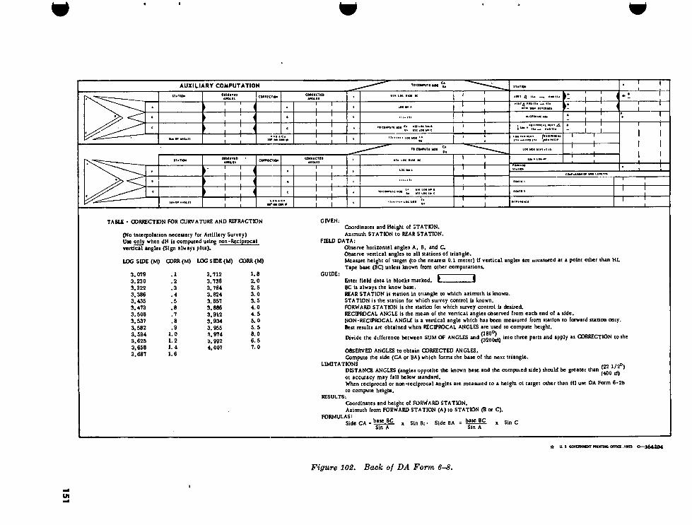
151
V
AUXILIARY COMPUTATION
H—h
i r
-I L
■ VK **U K
1 1"
I **■ U»—.
TOCOMMTI KM
H—h
j I I
TABLE - GORRECTDN FOR CURVATURE AND REFRACTION
(No inteipoUiion neceuary for Artillery Survey) Uie only when dH ii computed using non-Reciprocal vertical angles (Sign always plus).
LOG SIDE (M) CORK (M) LOG SIDE (M) 00RR (M)
3.079 3.230 3.322 3.386 3.435 3.473 3.508 3.537 3.562 3.584 3.625 3.658 3.687
.1
.2
.3
.4
.5
.6
.7
.8
.9 1.0 1.2 1.4 1.6
3.712 3.736 3.784 3.824 3.857 3.886 3.912 3.634 3.955 3.974 3.992 4.007
1.8 2.0 2.5 3.0 3.5 4.0 4.5 5.0 5.5 6.0 6.5 7.0
GIVEN: Coordinates and Height of STATDN. Azimuth STATION to REAR STATION.
FIELD DATA: Observe horizontal angles A. B, and C. Observe vertical angles to all stations of triangle. Measure height of target (to the nearest 0.1 meter) if vertical angles arc measured at a point other than HL Tape base (BC) unless known from other computations.
GUIDE: E 1 Enter field data in blocks marked.
BC is always the know base. REAR STATION is station in triangle to which azimuth is known. STATION is the station for which survey control is known. FORWARD STATION is the station for which survey control is desired. RECIPROCAL ANGLE is the mean of the vertical angles observed from each end of a side. NON*-RECIPROCAL ANGLE is a vertical angle which has been measured from station to forward station omy. Best results are obtained when RECIPROCAL ANGLES are used to compute height.
Divide the difference between SUM OF ANGLES and 'nt0 l^ree Part* *PP^y as CORRECTION to the
OBSERVED ANGLES to obtain CORRECTED ANGLES. Compute the side (CA or BA) which forms the base of the next triangle.
LIMITATIONS f22 1/2o. DISTANCE ANGLES (angles opposite the known base and the compuied tide) should be greater than ^ ;
or accuracy may fall below standard. When reciprocal or non-reciprocal angles are measured to a height ot target other than HI use DA Form 6-2b to compute height.
RESULTS: Coordinates and height of FORWARD STATION. Azimuth from FORWARD STATION (A) to STATION (B or Q.
FORMULAS: L
Side CA = ba>e-BIL x Sin B; • Side BA = bajS-BC x Sin C Sin A Sin A
£ U. S GOVERNMENT HUNTING OFFKZ. 1953 O—364204
Figure 102. Back of DA Form 6~8.

and the sum of the interior angles must be 180°. However, as actually measured in the field, the sum of the angles will usually vary from 180° by a few seconds. If this amount is within tolerance (app II), the angles are ad- justed to equal 180°. This is done by distribut- ing the closure correction (the closure error with the sign reversed) equally among the three angles. The remainder is applied to the larger angle (s). The following example illus- trates the procedure for adjusting the angles of a triangle:
Measured angle* Correction Corrected angUs
A = 54° 07' 29" -1" 54° 07' 28"
B = 78° 30' 27" -2" 78° 30' 25"
C = 47° 22' 08" -1" 47° 22' 07"
Sum = 180° 00' 04" Sum = 180° 00' 00"
248. DA Form 6—8 a. DA Form 6-8 (figs. 101 and 102) is used
for the computation of triangulation schemes. In computing single triangles or chains of single triangles, only the front side of the form is used. In computing quadrilaterals, both the front and back sides of the form are used (par. 253). It is of prime importance to insure that proper orientation is made of the triangle to be computed in the triangular sketch on the front of the form. The known base of the triangle to be computed must always be repre- sented on the sketch as in line CB. A sample computation is shown in figure 101.
b. Entries required are as shown in figure 101 and appendix II.
c. Formulas to be used are shown on the back of the form (fig. 102).
249. Height Determination in Triangulation
a. Vertical angles at each end of a side should be measured reciprocally to the height of instrument (HI). Frequently, due to dis- tances involved, the instrument operator must measure the vertical angle to a target erected over the forward station. When the vertical angles are measured reciprocally at HI, the heights of triangulation stations are computed on the DA Form 6-8. If the length of the side is greater than 1,000 meters and/or if the vertical angle is not measured reciprocally, the
table of curvature and refraction corrections on the reverse side of DA Form 6-8 must be used. To enter the table, use the log length of the side along which the height is being ex- tended.
6. When the vertical angle is measured to a target erected over the station or to any point other than height of instrument, the height of the unknown station is computed on DA Form 6-2b (fig. 90). Complete instructions for the use of DA Form 6-2b are contained on the reverse side of the form (fig. 91). At each station, the height of instrument and the heights of any points which could conceivably be used as a target by other parties will be recorded. Prior to performing the computa- tions, the parties compare notes and determine the heights of targets and heights of instru- ments to be used.
c. In any triangulation scheme, the coordi- nates and height of at least one station must be known. This station is used as the starting point to obtain the height of the next station. The height control is extended along the for- ward line of each triangle in the scheme. In figure 103, using the height of point C as a starting point, the height of point B is first determined since the height of point A must be computed along the forward line, BA. Once the height of B is determined, the height of A can be determined. Using the height of A, the height of D is computed and from D, the height of E is determined.
E
D
Height of point C is known, //in- dicates forward line.
Figure 103. Schematic drawing showing route of trigonometric height computations.
152

Section III. QUADRILATERALS
250. General
A quadrilateral is a triangulation scheme. The difference between a quadrilateral scheme and a single chain of triangles scheme is that in a quadrilateral two interior angles are meas- ured at each point, resulting in two diagonals as shown in figure 104. In effect, the result is two single chains of two triangles each, one superimposed on the other; if separated, they would appear as two single chains of triangles
as shown in figure 105. Triangles ABC and ACD form one chain, and triangles ABD and BCD form the other. It is apparent that if side DC were of known length and side AB were the desired side (forward line), the length of side AB could be computed through two separate schemes, thus introducing a check feature into the fieldwork and computations. For this reason, the quadrilateral scheme is preferred over the single chain of triangles.
Forward line
Direction of control extension
Base
Figure 10i. Schematic drawing of a quadrilateral.
FORWARD LINE FORWARD LINE —-a
/ /V" BASE BASE \.c \'C
_FORWARD_LINE FORWARD LINE FORWARD LINE
BASE BASE BASE *
ONE CHAIN OF TRIANGLES IN THE QUADRILATERAL
* — —À OTHER CHAIN OF TRIANGLES IN THE QUADRILATERAL
Figure 105. Schematic drawing of a quadrilateral separated into two single chains of two triangles each.
153

251. Fieldwork for Quadrilaterals Since any quadrilateral is basically a net-
work of triangles and the computations will follow the same general form as those for single triangles, the requirements for field- work are similar to those previously men- tioned. The distance angles must be greater than 22^2° (400 mils) and less than IST1/^0
(2,800 mils) and preferably between 30° and 150° (533 mils and 2,667 mils). The specifica- tions for desired accuracy are identical to those tabulated for triangulation (app. II).
252. Determining the Forward Line When a quadrilateral is computed, it is re-
duced to single triangles, and each triangle is computed separately. First, the azimuth and length of the base must be determined ; second, coordinates and height of one station in the scheme must be known ; third, the values of the interior angles and vertical angles at each sta- tion must be measured; and fourth, the for- ward line must be determined in order that its length may be computed. In a single quad- rilateral, the forward line is always the side opposite the known side, or the side in the di- rection in which control is being extended (fig. 104). If the scheme contains a chain of quadri- laterals, the forward line is that side which is common to adjacent quadrilaterals.
253. Strength of Figures Assume that the quadrilateral in figure 104
is to be computed. The coordinates of points C and D are known, so the azimuth and length of the base can be computed on a DA Form 6-1. Each point is then occupied, and the in- terior and vertical angles are measured. Since side CD is the known side, the opposite side (AB) will be the forward line. The basic quadrilateral (fig. 104) is really two single chains of triangle (fig. 105). It would be pos- sible to compute through both chains and ar- rive at the coordinates and height of points A and B and the distance between them, aver- aging the results to obtain a final answer. However, this method would not only be time- consuming but could produce highly inaccurate results. By use of strength of figures, one chain is chosen as the principal route (Rl) through which the coordinates and length of the forward line is computed. The other chain
provides another route (R2) by which only the length of the forward line is determined. If the two log lengths in DA Form 6-8 agrce within five digits in the fifth decimal place (0.0000500) of the mantissa, then the field- work and the computations are assumed to be correct. If they do not agree within the toler- ance, then an excessive error has been made, and the work must be rechecked.
254. Distance Angles The strength of the distance angles in the
chain will determine which chain is to be Rl and which is to be R2. The chain containing the stronger combination of distance angles will produce the more accurate answer and will be the Rl chain. The weaker chain will be the R2 chain. To determine the stronger chain, a table may be used (figs. 106 and 107). The two distance angles of each triangle, rounded off to the nearest degree or mil indicated in the figures, are used to enter the appropriate chart. The factors obtained for each triangle of a given chain are then added, and the chain containing the smaller total value is the stronger, or Rl, chain. Figure 108 illustrates the determination of the Rl and R2 chains. When the distance angles are used to enter the strength of figure table, the relative strength of the chain on the left is found to be 5 and the relative strength of the chain on the right is found to be 6. The chain on the left is the Rl chain.
255. Computation of Quadrilaterals DA Form 6-8 is used to compute quadri-
laterals (figs. 109 and 110). One form is used to compute each quadrilateral. The Rl chain is computed on the front of the form and the R2 chain is computed on the back. Only the log distance of the forward line is sought from the R2 chain. In solving quadrilaterals, first compute the log length of the forward line through both chains. If the log lengths agree within 5 in the fifth place of the mantissa, the fieldwork and computations up to that point are correct. Computation may then be con- tinued to solve for the desired coordinates. This procedure will save time, in that if the log lengths do not agree, the previous work must be rechecked, and the solution for the co- ordinates would not have to be redone, which would be the case if the entire front of the
154

»
10° 12° 14° 16° 18° 20° 25° 30e 33° 40° 43® 30° 53° 60° 63° 70° 75° 80° 85° 90° 10 12 14 16 18 20
428 339 315 284 262 245
339 259 253 225 204 180
233 214 187 168 153
187 162 143 130
143 126 113
113 100
22 24 26 28 30
232 221 213 206 199
177 167 160 133 148
142 134 126 120 IIS
119 III 104 99 94
103 95 89 83 79
91 83 77 72 68
64 58 34 SO
43 40 33
35 40 45 50 55 60
188 179 172 167 162 159
137 129 124 119 115 112
106 99 93 89 86 83
85 79 74 70 67 64
71 65 60 57 54 51
60 54 50 47 44 42
38 34 32 30 28
33 29 25 23 21 19
27 23 20 18 16 14
23 19 16 14 12 I I
16 13
10 9
65 70 75 80 85 90 95
100
153 152 ISO 147 145 143 140 138
109 106 104 102 100 98 96 95
80 78 76 74 73 71 70 68
62 60 58 57 55 54 53 31
49 48 46 45 43 42 41 40
40 38 37 36 34 33 32 31
26 25 23 22 21 20 20 19
18 17 16 15 14 13 13 12
13 12 11 10 10 9 9 8
10 9 8 7 7 6 6 6
7 7 6 5 3 4 4 4
5 4 3 3 2 2 2 2
O 0 o o o
o o 0 o
0 0
105 110 115 120 125 130
136 134 132 129 127 125
93 91 89 88 86 84
67 65 64 62 61 59
50 49 48 46 45 44
39 38 37 36 35 34
30 30 29 28 27 26
18 18 17 16 »6 16
12 II
10 10 10
8 7 7 7 7 7
5 5 5 5 5 5
4 3 3 3 4 4
135 140 145 ISO 152 154 156 158
122 119 116 112 III 110 108 107
82 80 77 75 75 74 74 74
58 56 55 54 53 53 54 54
43 42 41 40 40 41 42 43
33 32 32 32 32 33 34 35
26 25 25 26 26 27 28 30
16 16 16 17 18 20
10 10 II 13
7 8 9
160 162 164 166 168 170
!07 107 109 113 122 143
74 76 79 86 98
36 59 63 71
45 48 54
38 42
33
Figure 106. Table for determining strength of figure factors (degrees)
form had been completed before proceeding to the back of the form.
a. Coordinate ¡. Computations. In a single chain of triangles, the forward line in the last triangle of the chain is always opposite the stronger angle. In a chain of quadrilaterals, the last forward line is in the R1 chain, and it may or may not be opposite the stronger angle in the last triangle. However, because
of the check obtained through the comparison of the Rl and the R2 chains, the accuracy of the coordinates obtained is assured.
b. Height Computations. Height computa- tions in quadrilateral schemes usually involve distances in excess of 1,000 meters, which re- quire determination of heights by use of DA Form 6-2b. For additional information see paragraph 249.
» 155

Milt <50 200 250 300 350 400 450 500 550 600 700 600 900 <000 «00 1200 1300 1400 1500 1600
150 200 250 300
350 400
605 465 334 391 272 347 233
320 210 300 192
212
176 155 139
143 123 109
104
91 78 450
500 550 600 700
600
283 178 272 <69 264 162 257 157 245 147
236 139
127
119 112 108 99
93
97
90 84
80 72
67
80
73 68 64 57
52
68
61 56 53 46
41
56
52 47 44 38
33
46 41
38 32
28
37 34 28
24
31 25
21
20
17 13 900 1000 1100 1200
229 133 223 129 218 125 215 123
88 84 81 79
62
59 56 55
48 45 43 41
38 35 33 31
30 27 25 24
25 23 21 20
21
19 17 16
19 14 II 17 12 9 15 II 8 14 10 7
<300
<400 <500 1600
211 119 207 117 205 115
202 112
76 74 72
71
52
51 49
48
39 37 36
35
29
28 27 26
22
21 20 19
18 17 16 15
15 13 14 12 13 II
12 10
3 2
3 2 2 2
0 0 O
1700 1800 1900 2000
199 MO 196 108 193 106 190 104
69 67 66 64
46 45
42
34
33 32 30
25 24
23 22
19 18 17 16
14 14 13 13
12 10 Il 9 Il 9 10 8
O O 0
2100 2200 2300 2400 2500
2600 2650 2700 2750 2800 2850 2900 2950 3000 3050
187 102 184 99 180 97
176 95 171
166 164 161 159 155 153
151 153 163
202
92
89 88 86 85 84 85 87 94 112
63 61 59
57 55 54 53 53 53 54 56
60 71
41 40 39
38 36 36 36 36 37 38 42
48
30 29 28 27 26
26 26 27
28 31 35
22 21 20
20 20
20 20 21 23 26
16 12 15 12 15 II
15 II 15 16 16 17
19
12 13 14 15
10 9 9
9 10 11 12
8 8 8 8 9
10
Figure 107. Table for determining strength of figure factors (mils).
35° 95°
60°
50 85° 35
Distonce ongles* 85°-60° * 2
Distance ongles *95°- 50° * 3
Total strength of figures 8 5
RI
40° 95
55°
45* 85*
40°
Distance ongles 8 85° - 55° 8 2
Distance angles 8 95°-45° *4
Total strength of figures 8 6
R2
Figure 108. Schematic drawing showing the determination of R1 and R2 chains.
156

157
TO CONFITE SIDE
790 OBSERVED CORRECTED UTM LOG B*SE PC
(It BC it téfêj, nrk .bletk to t¡tht) STATIOK CORRECT 10* 3792 *PED P»5E BC ANGLES ANGLES
I 1
,12 ,12 G CONVEÍJiflí FEET TO METERS ' « TT «» only •htn'BQ^l^ in foot) ¿0^*? 8 * | Q I 5 8 SC 91851 ,0208 4
-2 fO-CJ) SCP 2 LOG SCALE FACTOR 18 ,11 3 1939,3584
'C F9I |89 39T -2
180 iooSfe 180°0i
SCP ,29^7 TO COMPUTE SIDE 9 >999,8524 91 ASE BC
A*8*C » 180°0R 1200 r4 3 [939 I2I08 180 1OO1OO = LOG SIDE ANCLES
, j
STATION SCP 2 554 447 08 8401799 88 TO FIND STATION ANGLE AT C
1S9° 59**^ OR '■«00 TÍ
REAR SCP I VERT ¿i STA—»FWD STA 0E- 7 744 3 |95l STATION
Í99Í40I00 VERT-sdCnvO STA —* STA ■1TH SIGN REVERSED
AZIMUTH STARREM STA C (T). (I
ARE USED ONLV STATION
ANGLE 43 18 ALGEBRAIC SUM STATION ANGLE AT C FOR RECIPROCAL
. RECIPROCAL VERT 5TA-*FwD STA 242 58 t SUM : ANCLE AZ TO SEARING
~ U~l LOG TAN VERT-£Í /RECIPROCALE*) STA—*FMD STA ^ NON-REC I P («> 242 58 I 360
6000 m ¡nn^
180 LOG SIDE. REPEATTS)
LOG S ICE REPEOP)
LOG SIDE UPEATISJ
AZIMUTH STA-ÿfMO STA 242,58 3.939,2108 3 '939,2108 BEARING
~1~~ SUM = LOG dH
ft* 180° /*TSl200 I
LOG SIN BEARING
LOG cqs BEARING 180 dE- 62 ,58 II 9 949,7639 9 :657 ,4969 SUM = LOG dN
FORWARD MAM aa
3 596,7077 SCP 3 AZIMUTH C O C A II
FMD ST A-»ST A OC I DO I 11 546 ,702! 91 g3?i948:87 3.888,9747 LOG dE
TO COMPUTE SIDE
UTM LOG BASE BC (tf BC Ik topod, work block to r<AM)
OBSERVED ANGLES
ORRECTED ANGLES 3 !939 ,2108 TAPED BASE BC STAT ION CORRECTION
>90'09Í59Í ‘ 90 '09'57 9 '999 9982 LOG CONVERS ET TO METERS in /••(> SCP LOG SIN A
8 4.0 I 56
SCP 2 4Ó LOG SCALE FACTOR fl)-(R) 23 12 ,39 3 :939 ,2126
3« USE LOG SIN e SCP 3 ñ 66 37 24 595 6237 TO COMPUTE SID BASE
4P A»R»C = I A A 180° OR 32C0 rt J SO 180,00 00,00 534 ,8363 ANGLES a LOG SID (in* I)
'3 ,836,848 SCP 546,702 91 87 STATION TO FIND STATION ANGLE AT C
59 60 359° 59* 60
OR 6SOO [ft REAR C/*D O STATION bV/K £ VERT^sJ. STA—NFWD STA 359 218 34 419 42
VERT F WO STA—»STA WITH SIGN REVERSED
AZIMUTH STA-MTEAR ST A
CORRECTED ¿£C 62 66 7). if) ANDÍ*) 37,24 ARE USED ONLT
4. STATION T ANGLE
ALGEBRAIC SUM 293,22 36 293 22 ,36 FOR RECIPROCAL
A CUM . RECIPROCAL VERTwO. 1 5l1" STA—»FWO STA 356 ,20 ,47 ANGLE U_L£
LOG TAB VERT ¿i. /RECIPROCAL (t) 359 59,60 6aoo m NON-RECIP (*) STA—*FWD STA ¿¿¡¡J
356 20,47 LOG SI REPEAT
LOG SIDE. REPEAT!*)
AZIMUTH —*f<D STA
LOG SI REPEAT 534 8363 3 534 8363 356,20,47
3 39 ¡13 SUM n LOG dH
LOG SIN BEARING
LX COS BEARING 180 8.804,3053 9:999,1164 1200 m
SUM “ ' ' SUM s HG« 2.339,1416 LOca' sT.Tio. SC P 4 176 ,20,47 3 .533,9527 546,484! 57 3 ,840,268129
COMPUTER CHECKER Cpl Jonas CpI Smith I OF 2
If dn is conpaitd aalif tba DO»-r*ciproc»l T«rtic*l u|U froa STA to PVD STA; add corractiet for earaotart •ad rafactloa whaa lof aid* ia mora than 1,004
SHEET SHEETS 9
»6-8 REPLACES DA FORM 6-B, I NOV SI, WHICH WILL BE USED UNTIL EXHAUSTED. COMMÎT,OK - PUNE TRIANQLE COORDINATES ANO HEIGHT FROM ONE SIDE, THREE ANGLES AND VERTICAL ANGLES
Figure 109. Solution of Rl chain, fourth-order survey.

158
TABLE • CORRECTION FOR CURVATURE AND REFRACTION
(No interpolation necessary for Ahillery Survey) Use only when dH is computed using non-Reciprocal vertical angles (Sign always plus).
LOG SIDE (M) GORR (M) LOG SIDE (M) CORK (M)
3.019 3.230 3.322 3« 386 3.435 3.473 3.508 3.537 3.562 3.584 3.625 3.658 3.687
.1
.2
.3
.4
.5
.6
.7
.8
.9 1.0 1.2 1.4 1.6
3.712 3.736 3.784 3.824 3.857 3.886 3.912 3.934 3. 955 3.974 3.992 4.007
1.8 2.0 2.5 3.0 3.5 4.0 4.5 5.0 5.5 6.0 6.5 7. 0
GIVEN: Coordinates and Height of STATDN. Azimuth STATION to REAR STATION.
FIELD DATA: Observe horizontal angles A, B, and C. Observe vertical angles to all stations of triangle. Measure height of target (to the nearest 0.1 meter) if vertical angles are measured at a point other than HL Tape base (BC) unless known from other computations.
GUIDE: L 3 Enter field data in blocks marked. BC is always the know base. REAR STATION is station in triangle to which azimuth Is loiown. STATION is the station for which survey control is known. FORWARD STATION is the station for which survey control is desired. RECIPROCAL ANGLE is the mean of the vertical angles observed from each end of a side. NON-RECIPROCAL ANGLE is a vertical angle which has been measured from station to forward station omy. Best results are obtained when RECIPROCAL ANGLES are used to compute height.
Divide the difference between SUM OF ANGLES and jjjoortÿ l"t0 lhree par“ *n,) ip,ll), al a0RRECTI0N ,0 the
OBSERVED ANGLES to obtain CORRECTED ANGLES. Compute the side (CA or BA) which forms the base of the next triangle.
LIMITATIONS (22 1/2°) DISTANCE ANGLES (angles opposite the known base and the computed side) should be greater than J40Q ^ or accuracy may fall below standard. When reciprocal or non-reciprocal angles are measured to a height of target other than HI use DA Form 6-2b to compute height.
RESULTS: Coordinates and height of FORWARD STATION. Azimuth from FORWARD STATION (A) to STATION (B or C).
FORMULAS: . __ . nr
Side CA = baseBC x S1„ B. . SiBe BA = ^ie|C „ SlI) c Sin A Sin A
it US GOVERNMENT PRINTING OFFIŒ IMS O—364204
Figure 110. Solution of R2 chain, fourth-order survey.

256. Sequence in Quadrilateral Computations
The proper steps to take in computing a quadrilateral are as follows :
a. Isolate the quadrilateral from the quadri- lateral scheme.
b. Determine the R1 and R2 chains.
c. Compute the R1 chain on the front of DA Form 6-8.
d. Compute the R2 chain on the back of DA Form 6-8.
e. Compare the log distance of the forward line.
f. Determine coordinates, using the R1 chain. g. Determine heights, using DA Form 6-2b.
Section IV. CENTRAL POINT FIGURES
257. General When it is impossible to observe the diago-
nals of a quadrilateral, the central point is used. Two central point figures commonly used are shown in figures 111 and 112. Central point figures of six or more sides are not generally used because of the excessive time and the number of personnel required to accomplish the fieldwork.
258. Computation of Central Point Figures The solution of the central point scheme is
similar to the solution of the basic quadri- lateral. The R1 and the R2 chains must be
z 4
Figure 111. Central point quadrilateral.
determined. In figures 111 and 112, each scheme contains two chains of triangles, one going clockwise around the central point and the other going counterclockwise. In figure 112 if AB were the base and DC the forward line, the chain of triangles going clockwise would contain four triangles and the other chain of triangles going counterclockwise would contain only three triangles. However, the relative strength of the chain of four triangles may make it the R1 chain when it is compared to the relative strength of the chain of only three triangles.
Figure lia. Central point pentagon.
AI
P2
Figure 113. Schematic drawing of a three-point resection.
159

16
0
9 4 Í28 59 BlPf AT (30)
OOMPUTATION-COORDIHATES AND HEIGHT FROM THREE-POINT RESECTION 71 .02.10 REPEAT (T)
(11 + 13) 65 .31 .09 (A) PAC
AZIMUTH A TO C (PROM AUI COMP OM REV) 104 .24
1W OR noon 179 .59 ,60 MO* OR AAOOM
165 ,31 ,09 REPEAT (111
MORE THAN'Bl «flWnr, LEU THAN (A) 10-4(1) 104 24 14 ,28 ,51 UREY (M) - (13) « ANCLE A.
er«
MANB AZIMUTH A TO • IPSO« AUI COMP ON REV) 82 ,12 N ■
S pi* >TMPP ✓
3 862 .744 REPEAT (13
'P2 s (9) - (4) s ANCLE Ai
22 .11 LOC SIN (10) 9 998 .6693 4/
Û1ÎR1 OeSERVEO ANCLE P 48 .00 37 +<») 3:861 .4134 IF (14) 13 LES3 THAN (17) IMI4) 13 MORE THAN (17)
71 .02 OBSERVED ANCLE P3 9:975 .764 2 REPEAT (11)
815 ,4261 REPEAT (17, REPEAT (14) (S) + <4)+(7)
DO NOT ATTEMPT TO SOLVE PROBLEM «HEN THIS VALUE IS
OET.ZEH , ) ANO { Ef* }
(IV)-p (40) 3:885 .6492 3:733 9123 REPEAT (17) PEAT (14)
£2 141 4 26 OIOS! ,5 38
50:20:45
REPEAT 111) 3:839 ,6619 (13) - (IT) (18) -Ml») ANCLE VINC ANCLE HAVING
LOC TAN (30) 1W* OR )300*1 179 .59 60 LOC SIN (3* 9:917 .1538 LOC TAN (M>
49* OR BOOM 45 .00 .00 43* OR BOON 70 37 1/3 OF (B) 143)-f (43) 3 756 .8157 5 ,20 ,45 (31) - (33) (3D - (32)
109 22 .47 9) . (10) 91871 .1682 REPEAT (14)
8:971 1556 LOC TAN (33) LOC TAN (71, LOC CRIO DISTANCE A TO C (PROM AUI COMP OH REV, 3:839 ,6619 (44) —(43) 3 885.6475
0:45 3,7562 LOG TAN (ID LOC TAN 11)
91975 .7642 LOC SIN (7) 31885,6492 REPEAT (4D
91424 19 124) 4- (25) (24, *4 (25)
(13, + (13, 31815 ,4261 DIFFERENCE BETWEEN (44) ANO (47,
[MUST BE LESS THAN CLOOOl]
3 885 ,6475 109 22 47 REPEAT (ID REPEAT (ID
LOG CRIO DISTANCE A TO B (PROM AUI COMP ON REV)
ANCLE HAVl LOC TAN [U
ANCLE HAVING LOC TAN (34) 14 53 3 :862 ,7441 48 0:000,00I7
IF (37) IS IFV27) is, 139) IV (39, IS 9 871 1682 LOC SIN (4) 1/3 OF (41 01000.0008 MO* 1 (37) — \l400Mf (37) +
MORE THAN LESS THAN
(37, + (3B ) (37)— (3B,
MOREVTHAN -(21) + (2B) 124 16 35 LES HAN
REPEAT (44) OR (47) WHICHEVER IS SMAU.ER
<1S) + (14) 3 733 ,9123 3 885 ,6475 IF (37) IS. 30 IS IF (37) IV M IS MORE THAN LESS THAN
MORE THAN LESS THAN
(27) — (3B) (37) + (3B)
(37, -t-(2B) (27) — (3B) 94 '28 59 (49)+ ($0)3
LOC CRIO DISTANCE A TO P 3:885 6483 E 546 702 STATION A REAR STATION B PAC 94 3'836 848 87 329 '4
'632 & © 0,21 30' «A”.» 82 .12 ,38 VERT ** P TO A WITH SICH REVERSED .73 895 48 48: i AZ TO BEARINC 41-
4N* ITA ANCLE IEPEAT (341 14 28 51 179 59 60 LOC TAN
VERT .4 7 796 .170 2 377 :5
31885:6483 "'""Is!885 :6483 REPEAT
(31) 3:885 6483 29 96,41 ,29 Z 0 96 .41 BEARINC LOC SIN
BEARINC LOC CDS BEARINC 9:066 ,4059 377 5 9:997 ,0316 8185 i:68 LOC dH
dE- 83 18 31 AZIMUTH A TO P
SUM> LOC dN
SUM > LOC dE 3:882 6799 21952 :0542 - 4 96 .41 29 * *
♦ i IBO* -I »00H 373 '5 STATION P '554 335 67 -3'835 :953 ;39 01 * DIFFERENCE IN HEIGHTS OP TARGET ANO INSTRUMENT PROM GUIDE ON REVERSE
MM CORRECTION POR CURVATURE AMO REFRACTION PROM TABLE OM REVERSE COHPUTER Cp| Webb AZIMUTH CHECEER OF I SHEETS SHEET P TO A
ft A FORM UM 1 Fl» B» 6-19 PMKVIOUS «OITIOHJ OF THIS FORM ARK OBSOLETE
t*u S GOVERNMENT PAINTING OFFia IB96 O—17911)
Figure llí. Solution of three-point resection, fourth-order survey.

161
AUXILIARY COMPUTATION AZIMUTH AND DISTANCE FROM A TO B AND A TO C
FROH STATKM A RAC TO STATION B MAN IF A IS LCSS THAN B REPEAT A
IF AA IS BLANK, USE A-B. SION- IF AA IS FILLED, USE B-AA, SIGN*
COORDINATE
5461702 194
553 ,925 .95
546 ,702 .94
- 7 ,223 !0I dW-
3.858 ,7182
2 994,7921
0 .863 ,9261
COORDINATE
3 ¡836 |s48 ¡87
3,837 ,636 :95
3 ,836 ,848 187
i988 IPS
dE-
tfN-f
DETERMINE AZIMUTH FROM BEARING BY PUTTING « AND 4N ON SKETCH AS GUIDE
AZIMUTH A TO B
[ENTER IN (4) ON FRONT]
82 ,12 ,38
82 112 38
IF JE IS MORE THAN dN IF dt: IS LESS THAN
REPEAT LO REPEAT LOG dE 3 :858 ,7182
LOG SIN BEARING A TO B 9 .995 ,9741
LOG COS BEARING
LOG dE-LOG SIN BEARING« «■ IOC dtf^-rtc LOG GRID DISTANCE A TO B Û .00¿ ,r44l ^PBXRID 0IS1
ZOO COS BEARING« DISTANCE A TO B
[ENTER LOG GRID DISTANCE A TO B M <1S) ON FFONT ]
PROM STATION A RAC TO STATION C REY
IP AA IS BLANK. USE A-C. SIGN - «5"* 'eacU. IP AA IS PILLED. USE C - AA. SIGH+J **1= ^ IDJD .71
COORDINATE
* 546 ,902 .94
LOG dE - LOG dN> LOG TAN BEARING A TO C
4 , 553 ,398 165
546 ,902 :94
3 .825 ,7966
I I 3 1235 ,3492
0 590 ,4474
COOltDMATE
* 3!836!S48 ¡87
3,835 ,129 Is8
I ,719 129
dE- dN4>
dE+ dN-f
DETERMINE AZIMUTH PROM BEARING BY PLOTTING dE AND dN ON SKETOI AS GUIDE
AZIMUTH A TO C
[ENTER IN(1) ON PRONTJ
75 135 ¡56
179 .59 ,60
75~!35 :56
104 £L°i IF dE IS MORE THAN dN
REPEAT LOG dE
LOG SIN BEARING A TO C
318257966
9.9861347 I bOG COS BEARING
LOG dt -LOG SOI BEARINGS 'o'XAfCia LOGAM^CSG LOO GRID DISTANCE A TO C [3 . 05900l3 [>OOXRID 0IS1
IF IE IS LESS THAN
REPEAT LOG
.06 COS HEARING DISTANCE A TO C
[ENTER LOG GRID DISTANCE A TO C M (IZ) ON FRONT ]
TABLE - CORRECTION FOR CURVATURE AND REFRACTION
(NO INTERPOLATION NECESSARY FOR ARTILLERY SURVEY)
(SIGN ALWAYS MINUS)
LOR Side (M) Gon(M) Log Side (M) Con (M)
3.079 3.230 3.322 3.386
3.435 3.473
3.508 3.537 3.562 3.584
3.625
3.658 3.687
.1
.2
.3
.4
.5
.6
.7
.8
.9 1.0
1.2 1.4
1.6
3.712 3.736 3.784 3.824 3.857
3.886 3.912 3.934 3.955 3.974 3.992
4.007
1.8 2.0 2.5 3.0
3.5 4.0
4.5 5.0 5.5 6.0
6.5 7.0
GIVEN. Coordinates of stathxu A, 6, and C. Height of tut ion A.
FIELD DATA- Observe horizontal angles P¡ and Pç.
Observe vertical angle to station A.
Measure height of Instrument (to nearest 0.1 meto). Estimate height of target at Ration A, tí not known.
GUIDE: Enter observed field data in blocks marked d 3. When value tn (8) of computation is between 160° (2845ri) and 200° (3555dS), a new nation P
or new stations A,B( and/or C must be selected.
Find difference between heights of instrument and target as follows.
Known or Estimated Height of Target
Meastsed Height of fctttxument
Algebraic Sum a and b [Biter, with sign, in block marked Ik )
Oner correction fo curvature and refraction in block marked *«
LIMITATIONS:
Angfci P|, Pj, B. and C should be greater than 22 1/2° (400i¿) & accuracy may fall below nandard.
RESULTS: Coced ina tes and height of su lion P.
Azimuth from sution P to tutkm A.
FORMULAS
Tan 2 AC sin Pg AB tin Pj
ï 1/a (fcq h more th*1,{1!5£rt}:
Tan 1/2 (C-B) « Tan (£ - 45°) Tan 1/2 (B»C)
t 1/2 (fcC) h less than
Tan 1/2 (B-Q « Tan (E - 45°) Tan 1/2 (B»C)
Tan 2 * ?1 AC sin Pj
( l/J (6.Q b more ■l»o|1«Jrf;J:
Tan 1/2 (B-Q - Tan (2 • 45°) Tan 1/2 (B*Q
Il/2(B.Obta..h.o{1«g1Ä}:
Tan 1/2 (C-B) « TAD (2 - 45°) Tan 1/2 (B*Q
AC tin C sin P,
2 « an auxiliary angle readied only In the compuution (always between 45 and 90 deuces).
Figure 115. Back of DA Form 6—19.

Section V. RESECTION
259. Three-Point Resection Three-point resection is a method of obtain-
ing control from three known points which are inaccessible. The fieldwork required for the solution is relatively simple. However, before going into the field, several factors must be considered. In figure 113, points A, B, and C are the known points and point P is the occu- pied station for which coordinates are to be determined. A map reconnaissance is of prime importance. All points should be selected so that angles PI, P2, C, and B are at least 22%° (400 mils) and preferably over 30° (533 mils). In addition, if the sum of the angles PI, P2, and Al is between 160° and 200° (2,845 mils and 3,555 mils), no valid solution is possible. Fieldwork consists of measuring angles PI and P2 and the vertical angle from P to which- ever known point for which the height is also known, preferably point A.
260. DA Form 6-19 a. DA Form 6-19 is used for the computa-
tion of a three-point resection problem (figs. 114 and 115).
b. Entries required are the coordinates of points A, B, and C and the horizontal angles and vertical angle measured at point P.
c. The formulas to be used are shown on the back of the form.
261. Two-Point Resection Two-point resection is a method of survey
similar to three-point resection. In two-point resection, control is obtained from two known
Al
A2 B
Q2 Rl R2 Ql
Figure 116. Schematic drawing showing two-point resection.
points which are inaccessible. In figure 116 points A and B are the inaccessible points of known survey control. Points R and Q are points from which the other three points are visible. This scheme resembles a quadrilateral, except that the angles at points A and B are not measured. As with three-point resection, certain preliminary operations must be per- formed. Map reconnaissance is required to insure that all interior angles will be greater than 22Vk° (400 mils) and less than 157V20
(2,800 mils) and preferably between 30° and 150° (533 mils and 2,667 mils). Also points A and B must be visible from R and Q as well as R and Q must be intervisible. Fieldwork will consist of measuring angles Rl, R2, Ql, and Q2 and vertical angles to A from R and Q.
262. DA Form 6-18 a. DA Form 6-18 (figs. 117 and 118) is used
for the computation of a two-point resection problem. If only the coordinates of point R are desired, the section labeled TO LOCATE STA- TION Q, lines 36 to 40, are not used. Similarly, if only the location of point Q is desired, the section labeled TO LOCATE STATION R, lines 41 to 45, are not used.
b. Entries required are the coordinates of the points A and B and the horizontal and vertical angles at points R and Q.
c. The formulas to be used are shown on the back of the form.
263. Limitations and Use of Resection Unless a resection (two- or three-point) has
been checked by some other means, the general rule is that it cannot be used as a point from which to extend survey control. However, a battery center and the 01-02 target area base of a field artillery battalion could be located by using a two-point or three-point resection. If known points are available, resection probably would allow these points to be located more rapidly than traversing and would allow the unit to conduct unobserved fire much sooner. If necessary, corrections could be made later by traversing to a known point. Also, resection could be used to locate any single point, to check a location determined by some other means of survey, or to verify points of sus- pected known control.
162

Ot SERVIO ANO CI Ol
OSSIRVIO ANCLE R,
28 ,59,50 52 31 10
COMPUTATION • COORDINATES AND HEIGHT FROM TWO-POINT RESECTION
cm 6-200)
81 31 ,00 00SERVED ANCLE R, £Z_
(«♦(O [ENTER ON THIS LINE)
IZSL 59 ,60
{!»<} -<»!= AM6L» At
149 19 ,20 30 40 40
OBSERVED ANCLE 5fl_
REPEAT (J)
58,40 81 31 00
l S
(7)4(1) [INTER ON THIS LINE]
179 ,59 ,60 140 29 40
3 U LOO UN (10) 9¡803 ¡5616
21 ANCLE HAVING LOG TAN (20)
REPEAT (ID
ANCLE HAVING LOG TAN (25)
50 ¡32 ¡51 45 jOO 00
5 ,32,51
8:987 ,3238 9 1935 4612 8.922 ,7850
40,45,30 4 47 07
35 58 .23 tirt
3) REPEAT (10)
REPEAT (20) OR (2$), ANGLE
33 (33)4- (34)
39 ,30 ,20 35 58 23 75 28,43
TO LOCATE STATION 0
31479 ¡567a 9 !985 ,8996- 3 465 4668 91932 .9643 31532 5025
{iSU 39 30 .20 9~685 15332 45 132 37 TO LOCATE STATION R
40 45 30
9 707.7484 (H)+(17)+(IS)
9'932 .9643 9 899 '5797
1$ (12)4(13)4(14) -h
9:540 2924
MORI THAN (IS)
LESS THAN (IS)
(20) IS.
(1S)-(I*)
9:966 15675
3CEŒ33 91540 ,2924
MORE THAN (13)
LESS THAN (IS)
(JO) IS.
(28)
(20)
AND (34) IV
(20)
(28)
9~!455 16623 01084^6301
REPEAT (28) OR (20). ANGLE A. 45 32 30 ,40,40 76 113 ÎÏ7
LOG GRID DISTANCE A TO B (PROM AUX COMP ON RE V)
91768 .9374
(43)-(44): LOG GRID DISTANCE A TO I
31479 ,5672
31248 ,5046 91966 '5675
?'28i am REAR STATION I
CARLTON AZ A TO B (PROM REV)
STA ANCLE 2IPEAT (301
AZIMUTH A TO 0
4\ 110« r) ^
46,42,25 45,32,37 92, 15,02
92.15 ,02 180 00 00 272 ,15 .02
TO LOCATE STATION 0
AZ TO BEARING
179.59,60 92.15.02
87,44,58
GRUBER [VERT ^ 0 TO A I VITH SIGN REVERSED
R^EAT|._ *__|R|P«AT I I I
«oí 31532 ,50251 i.w 13 532,5025 LOC SIN BEARING
SUM* LOG dl
91999 ,6648
31532 ,1673
LOG COS BEARING
SUM- LOG dN
81594 ftS54
2:i26 ,5579
LOC TAN VERT ^ REPEAT
(40)
.47;00( «î 3 s! 13518510 31532 15025 II668i3535
JIM
'541,835170
545
405139
I
241 109
3'835'349 loo
3¡835
3 835
133183
I
215 117
,48810
46 16
,441 14 2l4
,44318
ola 144310
REAR STATION 6 CARLTON AZ A TO B . -, - _ * _ (PROM REV) 46 .42,25
3M* «400 «t
AZIMUTH A TO R
76 .13 17
122 ,55 42
122^55^42
dl- dM +
AZ TO BEARING
179 ,59,60
122 ,55,42
57 ,04 ,18
TO LOCATE STATION R CRUDER '541 835 l70
REPEAT (41) 3l28ll937l
91923 9437 S^OS 18808
REPEAT (4S)
LOC COS BEARING
SUHs LOC dN
31281 19371
9 7?5 |37M 31:017,12082
LOC TAN VERT 4X 8 1427 ,6176 REPEAT
(4S)
-Qi I32001«- I 606 ISO
349100 48810
S I 040142 51 ¡2
31281 19371 I
436 Is - 214
I 1709,5547 ,439 12
' 543;442l20 "3'+834:308l58 -h
13 N W
8Í 180 00 00 302 55,42
DIPPERENCE IN HEIGHTS OP TARGET AND INSTRUMENT PROM GUIDE ON REVERSE
CORRECTION POR CURVATURE AMD REPRACKON PROM TABLE OH REVERSE
BILL 438 19 Col Jona» Col Smith I SHEET I or I .MEET.
DA ^,*6-18 PREVIOUS COITIONS OF THIS FORM ARC OBSOLETE. THIS FORM TOGETHER BITH DA FORMS 6-2, 6-8 AND 6-l() REPLACES OA FORM 6-2l, 1 OCT }2, WHICH IS OBSOLETE.
Figure 117. Solution of two^point resection, fourth-order survey.
FO
XT
RO
T
12 S
EP 6
0

AUXILIARY COMPUTATION
AZIMUTH AND DISTANCE FROM A TO B
FROM STATON A
TO STATION •
IF A IS LESS THAN •
REPEAT A
IF AA IS tLAMK, USE A- B, SIGN-
IF AA IS FILUaUSE B*AA. SKN4-
E COORDINATE
A 541 1835 ITO
LOG 4C-LOG«ls
LOG TAN GEARING A TO G
544.031 160
541 ,835 70
2 .195 19 1 '
3.341 ,6126 -P
31315 .7185
01025 .8941
N COORDINATE
A 3 1835 I349 loo 3,837 .417 Î80
3,835^349 lOO
2 .068 18 ANGLE HAVING LOG TAN
BEARING A TO B
OP
z DETERMINE AZIMUTH FROM
BEARING BY PLOTTING dE
AND dN ON SKETCH AS GUIDE
AZIMUTH A TO B
RENTER ON FRONT]
46
EE4 dH—
T 1
42 ,25
H h
46 H 1
IF dE IS MORE THAN dN IF «B IS LESS THAN
3 ¡341 16126 REPEAT L REPEAT LOG dE
LOG COS BEARING LOG SIN BEARING A TO B 9 •<?<?? 04^4
LOG dE- LOG SIN BEARING«
LOG GRID DISTANCE A TO B
LOG dtebOG COS BEARING* LMXR» DISTANCE A TO B 3 >479 .5672 B IN (M) AND/OR (41) ON FRONT] [ENTER LOG GRID DISTANCE A TO
GIVEN: Coordinates of stations A and B.
Height of station A.
FIELD DATA:
Observe horizontal anglesQj, Oj. R}. And Rg. Observe vertical angle(s) from station(i) Q or (and) R to station A. Measure height(s) of instruments) at statlon(i) Q or (and) R to nearest 0.1 meter. Estimate height of target at station A, if not known.
GUIDE: Enter observed field’data in blocks marked E 3. Find difference(s) between heights erf instruments) and target as follows:
STATION 0 STATION R
Known or Estimated Height of Target
Measured Height(s) of Instrument
Algebraic Sum a and b (fenter, with sign, in block(s) marked *]
+ 40
- I
I© I -2.4
- I '6
© I -2.4
TABLE • CORRECTION FOR CURVATURE AND REFRACTION
(NO INTERPOLATION NECESSARY FOR ARTILLERY SURVEY)
(SIGN ALWAYS MINUS)
Enter correctlon(i) for curvature and refraction in block(s) marked.* #. LIMITATIONS:
Angles A}. A^, B^; Bn, Oj, C^. Rj. and Rg should be greater than 22 1/2° (400tfi) or accuracy may fall below specifications
RESULTS: Coordinates and heights) of station(s) Q or (and) R.
Azimuth(s) from statlon(i) Q or (and) R to station A. FORMULAS:
Aj ♦ Bj = Oj ♦ Rj
Log Side (M)
3.079
3.230
3.322 3.396 3.435
3.473
3.508 3.537 3.562
3.594
5.625 3.658 3.697
Caff (M)
.1
.2
.3
.4
.5
.6
.7
.8
.9 1.0 1.2 1.4
3.712
3.736 3.784 3.824 3.857
3.886 3.912 3.934
3.955 3,974
3.992 4.007
Con (M)
1.8 2.0
2.5 3.0
3.5 4.0 4.5 5.0 5.5 6.0
6.5 7.0
Tan Z = Sin A2 Sin Q2 Sin R2
Sin Bj Sin Qj Sin R^ Tan Z =
Sin Sin Qj Sin
Sin Sin Q2 Sin ^
Tan S(Aj - 83) = Tan + Bj) Tan(Z - 45°) Tan '¿(Bg - AJ = Tan %(A! + Tan(Z - 45°)
_ AB Sin (Bi ♦ Bg) y 3 Sin Og
AB Sin Bo AR - 4
Sin Ri
Z - an auxiliary angle required only in the computations (always between 45 and 90 degrees).
0. a oorumuT raonno arm : im 0 • Man
Figure 118. Back of DA Form 6-18.

Section VI. INTERSECTION
264. General Intersection is the method of triangulation
in which only two angles in a triangle are measured. The third angle is determined by subtracting the sum of the two measured angles from 180° (3,200 mils).
265. Specifications See appendix II for specifications and tech-
niques in triangulation.
266. Limitations a. As in triangulation, no distance angle in
the triangle should be less than 22^° (400 mils) or greater than 157%° (2,800 mils); an angle between 30° (533 mils) and 150° (2,667 mils) is preferred. The only exception to this is when intersection is used in target area sur-
Section VII.
268. General When optical intervisibility between points
and the need to extend control rapidly over relatively long distances precludes the use of some other method of survey, trilatération may be used. Trilatération is a method of survey through which control is extended by measur- ing the lengths of the sides of a triangle and computing the interior angles of the triangle from these lengths. The measurements are made using the tellurometer. This provides an accurate and rapid means of determining the lengths of the sides, thereby insuring deter- mination of angles which will permit the ex- tension of control to fourth- and fifth-order accuracies.
269. DA Form 6—7a a. DA Form 6-7a is used for the computa-
tion of the trilatération problem (fig. 119). b. Entries required for the form are the
UTM grid or sea level distances for the sides of the triangle. The longest side is always placed in block 1 of the form.
c. The formulas to be used as shown on the back of the form.
vey and then the apex angle should not be less than 150 mils and preferably should be at least 300 mils.
b. The accuracy of location of a point estab- lished by intersection is considered to be the same as the accuracy with which the points that established the base are located. However, survey can be extended from a point located by intersection only if that survey is of a lower accuracy than that of the intersected point.
267. Intersection Computations Intersection computations are the same as
those for triangulation except that, on the DA Form 6-8, the unmeasured angle must be com- puted and the angles in the triangle are not adjusted.
TRILATERATION
d. After the angles have been computed, they can be used in conjunction with the side lengths to extend coordinate control, provided a known direction is available. If sea level dis- tances were used on DA Form 6-7a, they must be converted to UTM grid distance when the coordinates are computed on DA Form 6-2. The log scale factor is used for this conversion.
270. Limitations of Trilatération a. Due to increased lengths of the sides and
lack of optical intervisibility in some cases, di- rection must be provided at points within the scheme by some means other than trilatération. This direction is carried through the computa- tions but some means must be used to place the direction on the ground where it can be used.
b. For best results, trilatération schemes should be planned so that distance angles, when computed, exceed 221
/^° (400 mils) and, preferably, exceed 30° (533 mils).
c. Extensive map and ground reconnaissance are required to insure sites with electrical line-of-sight capabilities and to insure that minimum distance angle requirements can be met from selected positions.
165

COMPUTATION - PUNE TRIANGLE
(Vmini Thrum Sidmrn)
RBODIRKD DATA’ ÖTM (rid Hies a, b, aid c.
OPTIONAL DATA Flue ÖTH (rid aiimotb liie a, b, or c.
KNOWN AZIMUTH
_TO_ ■+- -+-
Plaie UTN (rid coordiiates statioi A, B, or C.
KNOWN COORDINATBS
g. Sta. +
I -U _1_
KNOWN LENGTH • 91 127!O7
61 107,25
89.73 .53
M>JB* Âiwmym amm a •• iongmmt known »id*.
T T KNOWN LENGTH b 19 (ir> 3 ,785 ,8457 KNOWN LENGTH e 20 LOG SIN 1181 9 ,977 ,3186 ID + (21 + 131 242 .07,85
PH* 1-21 .03 .92
(191 (201 3 ,763 ,1643 OF (HI 22 LOG ID
91,27 ,07
3 .960 (3314 (D 23 (ZD - (221
P—t- 29 76 ,85
9 ,802 ,8329 39°T25' ,35" <51 - (61 ANGLE HAVING LOG SIN (23> = <’|
3~Í952 ,9633 LOG (7) 3 ¡473 7570 29 (131
LOG (91 4 ,082 9260 26 9 ,977 ,3186 (8) 191 7 556 6830 27 (291 + (261 3 ,930 ,2819 LOG 121 3 ,785
3^70
8457 3 ,960 ^314 12 (10) - (ID 8373 (27) - (28) ,969 ,9505
es^'ss1 Isi" 13 LOG (3) 3 ,952 9633 30 ANGLE HAVING LOG SIN 1291=5, =
(121 - (13) 9 ,817 8740 PARTIAL PROOF
19 10.000 0000 + (19) 9,817 ,8740 31 (181 71° ,38' ,36" 16 -§-0F (19) 9 ,908 ,9370 32 39°,25' ,35"
ANGLE HAVING LOG COS (16) = 35°49* MS' 33 (30) 68° ,55' ,51" 18 2 X (17) =q 71° ,38',36* 3'* 131)9(32)9(33)^^ 180° ,00',02"
REMARKS
Sea level distance lines a,b, and c.
COMPUTER CHECKER
DA 1 ET,* 6-7a Figure 119. Solution of trilatération problem, fourth-order survey.
166

PART FOUR
ARTILLERY SURVEY OPERATIONS AND PLANNING
CHAPTER 16
FIELD ARTILLERY BATTALION AND BATTERY SURVEY OPERATIONS
Section I. GENERAL
271. General a. Paragraphs 272 through 282 cover survey
operations for all field artillery battalions and batteries which have survey requirements, ex- cept field artillery target acquisition battalions and batteries. Survey operations for field artil- lery target acquisition units are discussed in chapter 18.
b. Survey operations are performed by sur- vey personnel in the field artillery battalions for the purpose of obtaining the horizontal and vertical locations of points to be used in de- termining firing data and for providing a means of orienting pieces, instruments, radars, and searchlights. Survey operations of sepa- rate or detached batteries are performed for the same purpose.
272. Battalion Survey Control a. Battalion installations must be located
with respect to a common grid to permit massing of the fires of two or more battalions. This grid should be the grid of the next higher echelon whenever survey control points on that grid are available or when it is desired to mass the fires of more than one battalion.
b. A battalion survey control point (BnSCP) is a point provided by a higher survey echelon for the purpose of furnishing survey control to the battalion. More than one such point may
• be provided for a battalion.
273. Survey Control Points on Grid of Next Higher Echelon
a. Survey control points on the grid of the
next higher echelon may be available in the form of—
(1) One or more trig points in the vicin- ity of the battalion installations. When available, trig points should be used as the basis for battalion survey operations if survey control points have not been established for the battalion by the next higher echelon.
(2) One or more survey control points which have been established by the next higher echelon in the vicinity of the battalion installations. These sur- vey control points should be used as the basis for battalion survey opera- tions.
b. After he has verified that the battalion survey data contains no error, the battalion survey officer should report to his commander and the survey officer of the next higher echelon any differences which may exist be- tween the battalion survey data and the data provided by the next higher echelon.
274. Use of Assumed Data When neither survey control points nor trig
points exist in the vicinity of the battalion (battery) installations, the battalion (battery) survey officer must establish a point and as- sume data for that point. This point (and its assumed data) establishes the battalion (bat- tery) grid and is used as the basis for the bat- talion (battery) survey operations. When the next higher echelon establishes control in the battalion (battery) area, the assumed data must be converted to that control.
167

275. Converting to Grid of Next Higher Echelon
a. When data for the point used as a basis for the battalion (battery) survey operations differ from the data for that point furnished later by the next higher echelon, survey data determined by the battalion (battery) will nor- mally be converted to the grid of the next higher echelon. The methods of converting survey data are described in chapter 26. Un- less the tactical situation causes the commander to decide otherwise, battalion (battery) data are converted when data differ by—
(1) Two mils or more in azimuth. (2) Ten meters or more in radial error. (3) Two meters or more in height.
b. If the next higher echelon should convert its survey control to a different grid, the bat- talion must also convert to that grid.
276. Use of Survey Methods Field artillery battalion survey operations
may be performed by using any or all of the artillery survey methods, provided the limita- tions of the selected survey methods are not ex- ceeded. A comparison of the different methods is shown below.
a. Traverse. For most artillery survey oper- ations, traverse is the best method to use be- cause of its simplicity, speed, flexibility, and accuracy when' performed over open terrain for comparatively short distances. In heavily wooded or rough terrain, the expenditure of time in performing a traverse is extensive.
b. Triangulation. Triangulation should be used in mountainous terrain where taping is difficult or impossible and in rough terrain that would require an extensive expenditure of time to traverse. In gentle rolling or flat, treeless terrain, triangulation should be used when a large area is to be surveyed. In such terrain, traverse is faster unless distances between sta- tions exceed 1,500 to 2,000 meters. Where dis- tances are large, triangulation will save time and personnel. However, more extensive re- connaissance is required for triangulation than for traverse. Distance and angle measure- ments to achieve any given accuracy when tri- angulation is used must be more accurate than for traverse.
c. Intersection. Locating the position of a point by using the intersection method is rela- tively simple and speedy. However, the method depends on intervisibility between the ends of the base line and the unknown point. Inter- section must be used to locate points beyond friendly front lines. When practicable, these locations should be checked by intersection from more than one base.
d. Resection. The resection method of locat- ing a point requires very little fieldwork. Re- section normally is used in artillery battalion survey to establish a survey control point or observation post(s) in areas where the only existing control is on points which are inac- cessible. It is used for improvement over map- spotted or assumed data. However, any location determined by resection must be checked by a separate determination (prefer- ably traverse or triangulation) at the first op- portunity.
277. Use of Astronomic Observation The problem of converting data to a common
grid is greatly simplified if survey personnel use correct grid azimuth to initiate survey op- erations. Correct grid azimuth can be obtained by astronomic observation. Battalion survey personnel should be trained in the determina- tion of grid azimuth by observation of the sun and stars using the altitude method and obser- vation of Polaris using the hour-angle method. They should also be trained in the transmission of direction by simultaneous observations.
278. Division of Battalion and Battery Survey Operations
a. The survey operations of a field artillery battalion (separate or detached battery) con- sist of one or more of the following :
(1) Position area survey. (2) Connection survey. (3) Target area survey.
b. The survey operations performed by a field artillery battalion or a separate or de- tached field artillery battery depend mainly on three factors, as follows :
(1) The type of unit (including assign- ment and mission).
168
(2) The availability of survey control. (3) The amount of time available in
which to perform initial survey oper- ations.
279. Sequence of Battalion (Battery) Survey Operations
Battalion (battery) survey operations are performed in the sequence listed below.
a. Planning (Which Includes Reconnais- sance). A general discussion of survey plan- ning is contained in chapter 20. In order to insure maximum effectiveness, battalion (bat- tery) survey operations should be planned and initiated prior to the occupation of position, whenever possible.
b. Fieldwork. Fieldwork consists of estab- lishing survey stations and measuring angles and distances necessary to determine required survey data. The assignment of personnel to accomplish the required fieldwork is deter- mined by the number of surveying parties available and the unit SOP.
c. Computations. Each survey computation must be performed by two computers working independently and, when possible, checked with a slide rule by the chief of party. Whenever possible, survey computations should be per- formed concurrently with the determination of field data. This will insure that errors are de- tected and corrected at the earliest possible time and will facilitate the early use of a sur- veyed firing chart.
d. Plotting. After the survey data have been determined, battalion survey personnel may be required to prepare the firing chart (FM 6—40).
280. Survey Operations of Searchlight Batteries
When suitable maps are not available, sur- vey operations are performed by personnel of searchlight batteries for the purpose of deter- mining survey data from which light direction personnel can determine orienting data for the searchlights. The survey operations which must be performed are those necessary to es- tablish the grid coordinates and height of each searchlight. If desired, a grid azimuth for orientation of the searchlights may be estab-
lished and furnished to searchlight battery personnel.
281. Survey of Alternate Positions Survey operations for alternate positions
should be performed as soon as survey opera- tions are completed for primary positions. The survey requirements for alternate positions are identical to the requirements for primary posi- tions.
282. Limited Time Survey Battalion (battery) survey personnel must
provide the best firing chart and the best means of orienting weapons in the time avail- able. When time is a consideration, the survey officer must plan and accomplish the survey operations necessary to furnish the fire direc- tion officer with an improved firing chart. The extent of the survey conducted and the meth- ods employed will depend primarily on the time available. The procedures used for ac- complishing the division of operations may be any combination of the following:
a. Position Area. (1) Map-spot battery centers (lay by
compass). (2) Map-spot battery centers and estab-
lish orienting lines by directional traverse or simultaneous observation. '■
(3) Map-spot battalion SCP, locate bat- tery centers, and establish orienting lines by open traverse from desig- nated battalion SCP.
b. Connection Survey. (1) Use map for connection survey. (2) Establish survey by firing. (3) Employ simultaneous observation or
directional traverse from battalion SCP to 01 or target area survey con- trol point (TASCP).
c. Target Area Survey.
(1) Map-spot both 01 and 02. (2) Map-spot TASCP and short traverse
to locate 01 and 02. (3) Map-spot TASCP and locate 01 and
02 by intersection from an auxiliary base.
(4) Map-spot critical points.
169

SeeîioirD DD. POS!TI©M ÂiEA SUiVEY
283. ©eraeral a. Survey control is required in the position
area of each firing battery of the field artillery battalion (both cannon and missile) and in the position area of the mortar platoon of the com- bat support company of the battle group. Posi- tion area survey is performed by battalion (separate or detached battery) survey per- sonnel for the purpose of—
(1) Locating weapons positions and radars.
(2) Providing means for orienting weapons and radars.
(3) Determining orienting angles for each firing battery.
b. The position area surveys for field artil- lery cannon and missile units are performed to a minimum prescribed accuracy of fifth order (1:1,000). When the TOE of the unit au- thorizes the aiming circle M2 as the instru- ment for position survey (separate batteries, mortar platoons), the survey is performed to a minimum prescribed accuracy of 1:500.
284. Terms Used im Conjunction With Position Are®) Survey
The following terms are used in conjunction with position area survey :
a. Battery Center. A point materialized on the ground at the approximate geometric cen- ter of the weapons position. The battery cen- ter is the chart location of the battery (FM 6-40). (The location of the battery center is designated by the battery commander or bat- tery executive. The survey officer may select a tentative battery center if the battalion (bat- tery) SOP so states.)
b. Orienting Line (OL). A line of known direction materialized on the ground near the firing battery, which serves as a basis for lay- ing for direction (FM 6-40). (The azimuth of the orienting line is included in the data re- ported to the fire direction center.)
c. Orienting Station. A point on the orient- ing line, established on the ground, at which the battery executive sets up an aiming circle to lay the pieces (FM 6-40). (The location of the orienting station is designated by the bat- tery commander or battery executive. The sur-
vey officer may select the location of the orienting station if the battalion (battery) SOP so states.)
d. Registration point. A point in the target area the location of which is known on the ground and on the firing chart (FM 6-40).
e. Orienting angle. The horizontal, clock- wise angle from the line of fire to the orienting line or the orienting line extended : it is never greater than 3,200 mils (FM 6-40). (The orienting angle determined by survey person- nel is computed by subtracting the azimuth of the desired line of fire from the azimuth of the orienting line, adding 6,400 mils if neces- sary. For very heavy artillery, a similar angle is determined for each piece.
/. Radar orienting point. A point which is used to orient the radar. The radar orienting point for field artillery radar sets is established in a direction as nearly in the center of sector of search of the radar as possible. (The radar officer furnishes to the survey officer the ap- proximate azimuth on which the radar orient- ing point should be established.)
285. Meîlhod of Peirîoirmîinig Posifioira Area Survey
a. Except when time is limited, a closed traverse is used to perform the position area survey. The position area survey is initiated at a survey control point, the point that estab- lishes the unit grid, or a station established by the connection survey. The survey is closed on the starting point or on a station established to an accuracy equal to or higher than that of the survey being performed.
&. If a terrain obstacle, such as a wide stream, prevents the use of a closed traverse throughout the entire position area, triangula- tion must be used to cross the obstacle. How- ever, the number of triangles used should be kept to the minimum.
286. Survey for Wessums P@sîffD©mis a. In surveying a weapons position, an
orienting station is established near the bat- tery center. Normally, this point is used as one end of the orienting line, and the traverse leg used to establish the station is used as the orienting line; this keeps the orienting line in
1170

the closed traverse and reduces the chance of an error in the azimuth of the orienting line. If a traverse leg cannot be used as the orient- ing line, a prominent terrain object at least 300 meters away should be used. The azimuth of this line is determined by measuring the angle from the last traverse station to the selected point at the orienting station. In all cases for night operations, the orienting line must be prepared for orientation of the wea- pons at night; this is accomplished by placing a stake equipped with a night lighting device on the orienting line approximately 100 meters from the orienting station. (When an inter- mediate point cannot be established on the ori- enting line, an alternate orienting line is established on which the night orienting point can be set up. )
b. The coordinates and height of the battery center are determined by establishing a tra- verse station or an offset (an open traverse leg) from the orienting station to the battery center. (For very heavy artillery and missile units, the coordinates and height of each piece or launcher are determined by an offset from the orienting station.)
287. Survey for Radar
If the radar is not in position at the time the survey is performed, either the stake mark- ing the radar position or the stake marking the radar orienting point is used as a traverse station (1 and 2, fig. 120). If the radar is in position at the time of the survey, the stake marking the radar orienting point is used as a traverse station (3, fig. 120) or as a direc- tional traverse station (4, fig. 120). (If the radar is in position, horizontal and vertical angles for the radar are measured to the tele- scope on the radar parabola. )
a. The orienting azimuth for the radar can be determined in one of two ways—by measur- ing, at the radar position stake, the horizontal angle for the rear traverse station to the ori- enting point stake (1, fig. 120) or by measur- ing, at the orienting point stake, the horizontal angle from the rear traverse station to the radar position stake (2, fig. 120) or to the radar telescope (3 and 4, fig. 120). If the azimuth is determined at the orienting point stake, 3,200 mils must be added to, or subtracted from, the
determined azimuth to obtain the azimuth from the radar to the orienting point stake.
b. The vertical angle for the radar can be determined in one of two ways—by measuring, at the radar position stake, the vertical angle to the orienting point stake (1, fig. 120) or by measuring, at the orienting point stake, the vertical angle to the radar position stake (2, fig. 120) or the radar telescope (3 and 4, 120). (If the vertical angle is measured at the ori- enting point stake, the vertical angle at the radar will be opposite in sign to the measured angle.) If the vertical angle is measured to a stake, it must be corrected for the height of the radar telescope about the ground. (This correction can be determined by the mil form- ula ; i.e., by dividing the height above the ground of the radar telescope (in meters) by the taped or paced distance between the radar position stake and the radar orienting point stake (in thousands of meters).) If the vertical angle is measured to the radar telescope, it is not necessary to determine a correction for the vertical angle. The telescope on the radar antenna and the survey instrument are pointed at each other. The vertical angle measured by the survey instrument (with the sign changed) is set on the vertical angle scale of the radar. The vertical angle to the orienting stake is then measured with the radar.
c. The coordinates and the ground height of the radar are determined from the traverse data (1, fig. 120) or by establishing an offset (2, 3, and 4, fig. 120). The vertical angle used to determine the ground height of the radar is measured to the height of instrument regard- less of the manner by which the vertical angle for the radar is determined. (If the vertical angle for the radar is determined by measur- ing to the radar telescope and the radar location is determined by an offset from the radar ori- enting point (3, fig. 120), a vertical angle to the height of instrument must also be measured.) The vertical angle to the height of instrument is used to compute the ground height of the radar. The height of the radar parabola is then determined by adding to the computed ground height of the radar the vertical distance in meters (measured with a tape to the nearest 0.1 of a meter) from the ground to the center of the radar parabola.
d. If the theodolite is used to perform the
171

0 RADAR ORIENTING POINT
(Measure vertical angle)
(Pace to determine correction to
, vertical angle) TS 5
IS
S' RADAR ORIENTING POINT
TS 5
(Measure vertical angle)
RADAR NOT IN POSITION
RADAR ORIENTING POINT X 0
((Measure one vertical angle to telescope)
'(Measure a second vertical angle to HI)
( Measure vertical angle)
RADAR ORIENTING POINT
h
TS 5 TS 4
RADAR IN POSITION
SOLID LINES INDICATE DISTANCES DETERMINED BY TAPING ARCS WJTH ARROWS INDICATE MEASURED ANGLES
Figure 120. Locating and orienting a radar.
position area survey, the radar (or radar posi- tion stake) can be located by intersection (or triangulation). In this case, the radar orient- ing point is established and is used as a traverse station. The orienting point is also used as one end of an intersection (triangulation) base.
The next traverse station is used as the other end of the base. The base is double-taped to a comparative accuracy of 1:3,000 either by two taping teams or by one taping team taping the base twice. The radar is located and oriented as discussed in a through c above.
172

Section III. CONNECTION SURVEY
»
»
288. General
a. Connection survey is that part of the survey operations performed by battalion (separate battery) survey personnel for the purpose of locating the target area survey and the position area survey on a common grid.
b. Connection surveys are performed to a prescribed accuracy of fifth order.
289. Methods of Performing Connection Survey
a. A closed traverse normally is used to per- form the connection survey although triangula- tion or intersection can be used when the ter- rain is unsuitable for traverse. The connection survey locates one or more of the target area base observation posts or it may establish a target area survey control point from which target area base survey operations are initiated by another survey party. The connection sur- vey is initiated at a battalion SCP or the point that establishes the battalion grid. When the connection survey is initiated at a battalion SCP, it may close on the battalion SCP or on
any other survey control point established to an accuracy of 1:1,000 on the same grid as the battalion SCP. When the connection survey is initiated at the point that establishes the bat- talion grid (i.e., when data for the starting point is assumed), it must close on the starting point. (This point does not become the bat- talion SCP unless survey control for the point is established by the next higher echelon of survey. )
b. The survey party performing the connec- tion survey must locate at least one observation post (designated 01) of the target area base or a target area survey control point (TASCP). The coordinates, the height, and an azimuth from which the azimuth of the bases may be determined for the target area observation post(s) are furnished to the survey party per- forming the target area survey.
c. In many cases, heavy or very heavy artillery units need no connection survey. If target area survey operations are to be per- formed, the control is obtained from that con- trol which is based on the same grid established by a light or medium unit.
Section IV. TARGET AREA SURVEY
290. General a. Target area survey is that part of the
survey operations performed by battalion (de- tached battery) survey personnel for the pur- pose of establishing the target area base and locating critical points in the target area; i.e., registration point (s) and restitution points.
b. Critical points are surveyed to minimum prescribed accuracies of 1:500.
c. The target area base when established by the target area survey party is surveyed to a minimum accuracy of fifth order.
291. Terms Used in Conjunction With Target Area Survey
a. Target Area Base. A target area base con- sists of two or more observation posts which are used to locate the critical points in the target area and/or targets of opportunity and to conduct center-of-impact and high-burst
registrations. (When there are more than two observation posts, any two of them form an intersection base. The controlling observation post is designated 01, whether it is on the right or left end of the target area base ; the auxiliary observation posts are designated 02, 03, etc. (FM 6-^0).)
b. Azimuth Mark for Target Area Observa- tion Post. An azimuth mark which is used to orient the instrument is established at the target area base for each observation post. The azimuth to the azimuth mark may be deter- mined by using the back-azimuth of a traverse or intersection leg used to locate the observa- tion post, by computing the direction to some well-defined known point, or by using the ad- jacent observation post (where OP’s are intervisible). An auxiliary or intermediate ori- enting point should be established for night operations.
173

292. Selection of Observation Posts a. Initially, two or more observation posts
are selected at points from which the critical points in the target area are visible. If pos- sible, the distance between any two observation posts should be sufficient to insure a minimum angle of intersection at any of the critical points of 300 mils (aiming circle). These mini- mum angles at the critical points in the target area are necessary to insure results that ap- proach the accuracies prescribed for target area survey. If the observation posts of the target area base cannot be located sufficiently far apart to provide a minimum angle or inter- section of 300 mils, they should be located as far apart as possible. In any case, the distance between observation posts that are used as the ends of an intersection base must be sufficient to provide a minimum angle of intersection of 150 mils (aiming circle) at any critical point in the
target area. (The consistent accuracy that can be obtained from the location of points with angles of this minimum size is approximately 1:200.)
b. The location of each critical point should be checked from at least two intersection bases. As soon as possible, additional observation posts should be selected to provide this check. In addition to providing the check, observation posts should provide observation in the unit’s zone of action, especially of those areas which are not visible from the observation posts orig- inally selected.
293. Methods of Performing Target Area Base Survey
a. The method of survey normally used by the survey party in the field artillery battalion to perform the target area base survey is a closed traverse, or when the terrain allows and the enemy situation is such that traversing to
(TASCP) COMPUTED AZIMUTH AND DISTANCE
OZ
TARGET AREA PARTY
á BASE DOUBLE TAPED
(1/3000)
O Ol ESTABLISHED BY
CONNECTION SURVEY PARTY
CONNECTION SURVEY 1/1000
(OP'S NON INTERVISIBLE)
«
«
COMPUTED LENGTH 02
(TASCP TARGET AREA PART
CONNECTION SURVEY*^^-
© OP'S ESTABLISHED BY
TARGET AREA PARTY
l/IOOO (OP'S INTERVISIBLE)
174
Figure 121. Target area base survey.
«

»
»
an OP would disclose its position, triangulation is used. On some occasions it may be necessary to locate the OP by intersection or offset from a traverse station in the vicinity of the OP. The OP’s are located to an accuracy of fifth order.
b. In issuing the survey order, the survey officer will designate which of the survey parties is to perform the target area base survey. The specific location of both OP’s may also be designated or an approximate location given and specific location left to the discretion of the chief surveyor or chief of party. The location of a target area survey control point will be given; or, if one OP is located as part of the connection survey, it may be designated as the target area survey control point.
c. The observation posts are designated 01 and 02. 01 is considered the control OP and is plotted on the firing chart. 01 may be the OP on the right or left. 01 is always that OP requiring the least amount of fieldwork to establish its location. Less directional accuracy will be lost through angular measurements when the fieldwork and the number of main scheme angles are held to a minimum. Ex- amples of target area base surveys are shown in figure 121.
o Registration
Point /\
Restitution Point(s)
si I \
Ends of Base Intervisible
© Angle s Azimuth of Base- Azimuth to Critical Point
Any Critical Point
/ \
&
SURVEY
Angle ° Azimuth to Critical Point > Azimuth of Base
STATIONS IN CONNECTION
294. Method of Performing Target Area Survey
a. Intersection must be used to perform the target area survey. The length of each inter- section base of the target area base is obtained by computation from the coordinates of the two observation posts that establish the base. If the observation posts are intervisible, the azimuth of the base is determined by measuring the horizontal angle at an observation post from the rear station to the observation post at the other end of the base. If the observation posts are not intervisible, the azimuth of the base is determined by computation by using the co- ordinates of the ends of the base. (The length of the base may be determined by double-taping to a comparative accuracy of 1:3,000 when the base is located in an area not under direct ob- servation of the enemy.)
b. If the observation posts are intervisible, the interior horizontal angles are measured (1, fig. 122). If they are not intervisible, the angles at the ends of the base must be deter-
Ends of Base Not Intervisible
Figure 122. Target area survey.
mined by comparing the azimuth of the base with the azimuth from each observation post to the point being located (2, fig. 122). The azimuth of the line from each observation post is determined by measuring the horizontal angle at the observation post from the estab- lished azimuth mark (orienting station for .night operations) to the point in the target area. When the critical point does not present a clearly defined vertical line and cannot be accurately bisected, the horizontal angles are measured by using a special technique of point- ing. Pointings are made by placing the vertical line in the reticle on the right (left) edge of the object in measuring the first value of the angle and by placing the vertical line on the left (right) edge in measuring the second value of the angle. The mean angle obtained with this method must be verified by determining
» 175

at least one more mean angle by using the same technique. (When this technique is used to measure horizontal angles with an aiming cir- cle, two sets of pointings are made. The ac- cumulated value of one set (one pointing to each edge of the object) should agree with the accumulated value from the other set within 1 mil. The accumulated values of both sets are added together and divided by 4 to determine the mean angle to the nearest 0.1 mil.)
c. Vertical angles are measured to the lowest visible point on the object.
d. The distance from either end of the in- tersection base to each critical point is com- puted by using the base length determined in a above and the angles determined by direct
measurement (1, fig. 122) or by comparison of azimuths (2, fig. 122). The coordinates and height of each point are determined in the same manner in which they are determined by tri- angulation.
e. The party performing the target area sur- vey furnishes the location of the registration point(s) to the party performing the position area survey for computation of the orienting angle (s).
/. The locations of critical points determined from the target area base should be checked by establishing a second intersection base. (A second intersection base can be established by using a third observation post and either of the two observation posts used originally.)
176

CHAPTER 17
DIVISION ARTILLERY SURVEY
295. General a. Survey operations are performed by sur-
vey personnel of division artillery headquarters battery for the purpose of placing the field artillery units organic, assigned, or attached to the division on a common grid.
b. Division artillery surveys are executed to a prescribed accuracy of fourth order (1:3,000). Specifications and techniques for fourth-order survey are found in appendix II.
296. Division Artillery Survey Personnel A survey officer is assigned to the division
artillery staff. The division artillery survey officer plans and supervises the division artil- lery survey operations. He advises the com- mander and appropriate staff officers on mat- ters pertaining to survey. He coordinates the survey operations of the field artillery bat- talions (separate batteries) within the division.
297. Division Artillery Survey Information Center
a. A file of survey information and a survey information map are maintained in the survey information center (SIC) at the division artil- lery headquarters. The survey information center file and map are located at the division artillery command post and may be located in the division artillery operations section.
b. The survey information map shows the locations of survey control points and trig points and the schemes of all surveys per- formed by the division artillery survey section. The file of survey information consists of the trig lists prepared and issued by the Corps of Engineers, the trig lists prepared by the field artillery target acquisition battalion, and data for each control point established by division artillery survey operations. The data for each
control point established by division artillery are recorded on DA Form 6-5 (Record—Sur- vey Control Point) (figs. 123 and 124).
c. The division artillery survey officer should maintain close liaison with the corps artillery survey officer. By so doing, he can obtain data for survey control points which have been established by the target acquisition battalion in the division area. Use of these points can save time and can eliminate unnecessary dupli- cation of survey operations. He can also obtain data for points established in the vicinity of the target area which can be used by the battalion survey parties in performing the target area surveys and the target area base surveys.
298. Division Artillery Survey Control a. Division artillery battalions, batteries, and
other division installations that require survey control should be located with respect to a com- mon grid. This grid should be the corps grid whenever control points on that grid are avail- able. Control points on the corps grid are nor- mally available in the form of trig points and survey control points for which data are known with respect to the UTM (or universal polar sterographic (UPS) ) grid for the area of oper- ations.
b. When neither survey control points nor trig points are available in the division area, the division artillery survey officer establishes a point and assumes data for that point. This point (and its assumed data) establishes the division grid which is used as the basis for the division artillery survey operations. When the data for the point differ from the data for that point as established by the field artillery target acquisition battalion of corps artillery, survey data determined by the division artillery are converted to the corps grid. In the initial stages
177

of an operation, it is not necessary for division artillery to convert azimuth to the corps grid if it differs from azimuth provided by the tar- get acquisition battalion by 1 minute (0.3 mil) or less. However, it should be converted as soon as it is practicable. In any case, coordi- nates and height should be converted to the corps grid if they differ from the data provided by the target acquisition battalion.
299. Division Artillery Survey Operations a. Division artillery survey operations should
provide the best determination of data at the earliest possible time. Any of the artillery sur- vey methods may be used to perform the sur- veys. In areas where survey control points are not available in the vicinity of the battalion, common direction can be transmitted by simul- taneous observations. (Division artillery sur- vey personnel should be trained in the determi- nation of grid azimuth by astronomic and simultaneous observations.)
b. In addition to providing survey control points for battalions and/or batteries, the divi- sion artillery survey officer may designate points for which battalion surveys should deter- mine survey data in order to check the accuracy
of the surveys being performed by the bat- talions.
c. Normally, division artillery survey opera- tions are performed by the division artillery survey section.
d. When the time available to perform divi- sion artillery survey is limited, the division artillery commander may direct battalions of the artillery with the division to assist the division artillery survey section in performing the surveys necessary to establish the division artillery grid after the survey operations of the battalion have been completed. When this is necessary, the division artillery survey section should, at the first opportunity, reperform the portions of the survey performed by battalion survey sections.
e. When a target acquisition battery is at- tached to a division artillery, the survey parties of the target acquisition battery may perform part of the division artillery survey operations. The division artillery survey officer, in conjunc- tion with the target acquisition battery com- mander, plans and supervises the coordinated survey operations.
178

CHAPTER 18
CORPS ARTILLERY SURVEY
300. General
a. Corps artillery survey operations are per- formed by the field artillery target acquisition battalion assigned to each corps artillery head- quarters. The battalion commander of the field artillery target acquisition battalion is the corps artillery survey officer. The target acqui- sition battalion survey officer is responsible to the battalion commander for planning and supervising the battalion survey operations.
b. Survey operations are performed by sur- vey personnel in the field artillery target acqui- sition battalion for the purposes of placing the field artillery with the corps (and other units requiring survey control) on a common grid and of locating the target acquisition battalion installations (which include flash, sound, and radar installations). Also included in survey operations are the collection, evaluation, and dissemination of survey information for all surveys executed in the corps area to a pre- scribed accuracy of fourth-order or greater. Surveys performed by the target acquisition battalion are executed to a prescribed accuracy of fourth-order.
301. Survey Information Center
a. A corps survey information center is established and maintaned by the survey infor- mation center (SIC) personnel of headquarters battery of the target acquisition battalion. It is usually located in the vicinity of the corps artillery fire direction center. The SIC is an agency for collecting, evaluating, and dissemi- nating survey data. The dissemination is ac- complished by preparing and distributing trig lists and by furnishing survey information to personnel of other units upon request. Unless directed otherwise by the battalion commander,
all survey information is disseminated only through the survey information center.
b. Files of all survey control (fourth-order or greater) existing in the corps area and files of tie-in points established in adjacent corps areas by the target acquisition battalions or division artilleries in those areas are main- tained in the survey information center. These files consist of trig lists published by higher headquarters (including trig lists prepared by the Corps of Engineers), trig lists published by field artillery target acquisition battalions operating in the adjacent corps areas, and data for each survey control point established by the target acquisition battalion survey parties and by the parties of the division artillery head- quarters with the corps. The data for each survey control point established by the target acquisition battalion and by division artillery headquarters are recorded on DA Form 6-5 (figs. 123 and 124).
c. An operations map is maintained in the survey information center. The operations map shows the locations of all existing trig points and survey control points and the schemes of completed surveys. Overlays to the map show the survey operations that are currently being performed by the survey personnel of the target acquisition battalion (and division artilleries with the corps). The overlays also show the tactical situation, the location of each installa- tion of the target acquisition battalion, present and proposed artillery positions, and proposed survey plans.
d. In addition to performing the functions of the survey information center discussed in a through c above, survey information center personnel assist the survey operations of the target acquisition battalion by computing and
179

NAME OR DESIGNATION (sc» BECK
ssy 1 i
3 i rsr i Vo* i i i
ijrf 6 FT i o
LOCATED BY
J8T*Y ß, Ur F AT AB DESCRIPTION fO«n«r«J and «p«cifi« focctJoa«, *fp* of aork, ote.)
NOTEBOOK REFERENCE
B»OM //it 4 STATION /S /-INCH ¿/OJUOK/ t*
FO*T S/í¿ CENTSO. or 7-INCH SOUAXC e. o*estere /nt _
/ Oec /9&>o RECORDS FILED AT
i ÙSC /1¿>o áíQAX } S METEOS CU EST ONO /•£ NETS SS
/ST- /Nr D/y J*rr. S/c HOW LOCATED
TRIAK6ULATI ON TRI60MÛMETRIC
20 - ORDER
Sou TN 0F SovTHiNSST COf/YEA. O*
A/>¿- T30 77 ; AN FT Stet. MlUTAAV.
fisse év/rr/óN.
NAME OR DESIGNATION (4#- MK) I/ATZX Towel DISTANCE FROM SCPfPt. ». •ie.>
í I MEASURED cas ESTIMATED /¿lOO OfeTEJH DESCRIPTION CSpocific location, typo of mark, ate.)
AiIMUTH FROM SCP MATE* Tows A /» LA*6£ ST€€L. M0»
OETERMINED
CUTRIG LIST (ZD ANGLE TURNED I l M*P
CID TRAVERSE QÛ ASTRONOMIC r~~l OTWftt OUATE A Toutes. //V 1900 AßEN M OTHER Ai MKS VISIBLE FROM SCP
A/orre fir Sux. /IU/TANT ficseo ÿAT/QN .
fitAñY STATION ts HEP Lttftr Sv^S
ON TbP OP T-QAtEfi. (Station and AaiovtA »art DoaerIptlona Continuad on Sowaraa Sida)
DAi^e-S REPLACES DA FORM«6-91 1 OCT 92, «HIGH «ILL BE USED UNTIL EXHAUSTED.
RECORD - SURVEY CONTROL POINT
Figure 123. Entries made on front of DA Form 6-5
checking data. Computations and checks per- formed by the survey information center per- sonnel include the following :
(1) Checks of field records and computa- tions of field parties.
(2) Adjustment of traverses. (3) Conversion of survey data to the
corps grid when survey operations have been performed with assumed data.
(4) Transformation of coordinates and grid azimuths.
(5) Conversion of coordinates (geograph- ic to grid and/or grid to geographic).
302. Field Artillery Target Acquisition Battalion Survey Personnel
a. The target acquisition battalion com- mander is the corps artillery survey officer. Under the direction of the corps artillery com-
mander and assisted by the battalion survey officer, he—
(1) Plans the corps artillery survey.
(2) Coordinates the survey of the target acquisition battalion with all other artillery units in the corps area.
(3) Maintains liaison with, and obtains control data from, the topographic engineer unit operating with the corps.
(4) Establishes the survey information center.
b. The battalion survey officer is assigned to the battalion staff. The battalion survey officer plans and supervises the battalion survey operations, advises the battalion commander and the staff on matters pertaining to survey, and performs the coordination of the survey operations of all field artillery units operating in the corps area. An assistant battalion sur-
180 «

1 N
J1 I ü Ausr/u /?o
□□□□Il
Fi Ijorri isora t i'íi
A ߣCK
PO/HT TO ßE SIGHTED ON
SCP DESCRIPTION (Cont inu9d)
A* MK DESCRIPTION (Continued)
DESCRIPTION PREPARED BY
JÔNÊS DESCRIPTION CHECKED BY
Leo / Ote. /f£o
Figure 124. Entries made on back of DA Form 6—5.
vey officer, the survey platoon commander in headquarters battery, performs duties as di- rected by the battalion survey officer.
c. A warrant officer, assigned to headquar- ters battery, supervises the operations of the survey information center.
d. A survey platoon commanded by an of- ficer is assigned to headquarters battery and to each target acquisition battery of the target acquisition battalion. The officer is the survey officer of the battery. He plans and supervises the survey operations of the survey platoon. He advises the battery commander on matters pertaining to survey.
303. Coordination and Supervision of Battalion Surveys by the Battalion Survey Officer
The battalion survey officer normally is au- thorized by the battalion commander to issue instructions on matters concerning survey operations directly to the batteries. The battery
survey officers normally receive the survey in- structions for their batteries from the battalion survey officer. (The relations between the bat- talion survey officer and the battery survey officers in issuing and receiving instructions are similar to the relations between the fire direction officer in a howitzer or gun battalion and the battery executive officers.) The battery survey officers must keep their battery com- manders informed of the survey operations that they have been instructed to perform. They must also keep their battery commanders in- formed of the areas in which the battery sur- vey platoon will be operating and the progress of the survey operations.
304. Field Artillery Target Acquisition Battalion Survey Operations
a. Target acquisition battalion survey opera- tions are conducted in two phases—an initial phase and an expansion phase.
h. The survey operations conducted during
181

the initial phase consist of those necessary to establish a survey control point for each divi- sion artillery and each corps artillery battalion (and other points as directed by the battalion commander) and those necessary to establish survey control for the installations that are organic to the target acquisition battalion that require survey control.
c. The survey operations conducted during the expansion phase consist of the surveys necessary to place survey control points within 1,500 to 2,000 meters of any possible artillery position in the corps area.
d. The battalion survey officer designates to each platoon commander locations where sur- vey parties are to establish survey control points. These survey control points are estab- lished for later extension of control and for checking surveys.
e. Survey operations of the target acquisi- tion battalion are continuous. The amount of survey performed by the target acquisition bat- talion in any area of operations depends on the length of time that the corps remains in the area. When the corps is moving rapidly, the target acquisition battalion may be able to per- form only the initial phase survey operations. When the corps remains in one area for an extended period of time, the target acquisition battalion conducts extensive survey operations.
3@5. Use oí Assumed) Oeata
Whenever possible, survey platoons initiate survey operations at survey control points (or trig points). When adequate survey control points do not exist in the area of operations, one or more of the survey platoons must initiate survey operations, using assumed coordinates and height. When at least one survey control point exists in the area of operations, the sur- veys of the battalion are based on the grid established by the coordinates and height (s) of the survey control point (s). The surveys of the platoons that used assumed initial data are converted to the grid established by the survey control point (s). When no survey control points exist in the area, the battalion survey officer designates a point and furnishes as- sumed data for the point. (The assumed data should approximate the correct grid data as closely as possible.) The surveys of all of the platoons are then converted to the grid estab-
lished with the assumed point and the azimuth established at the assumed point.
3Û6. Azimyfîlhis
Azimuths at all points of the battalion sur- vey should be correct grid azimuths. Correct grid azimuth can normally be established by astronomic observation or by use of the gyro azimuth surveying instrument. When two in- tervisible survey control points (based on cor- rect grid data) or trig points exist, correct grid azimuth can be obtained from these points. If the correct grid azimuth between the points is not known, it can be computed by using the grid coordinates of the points.
307. Survey Comfrol Poomitfs
Survey parties of the battalion establish sur- vey control points approximately every 1,500 to 2,000 meters along the routes of the surveys. A station of this type is established at each point for division artillery, for corps artillery battalions, and for those points from which target acquisition battery installations are located. The same type of station is also estab- lished at each point designated for later exten- sion of control and for checking surveys. Each of these survey control points is marked by a hub and a reference stake. An azimuth for each survey control point is established either to an azimuth mark or to an adjacent survey control point. A description of each survey control point is prepared on DA Form 6-5 and forwarded to the survey information center for file.
3@S. POssniniBinig Taurgefî Acquisittoem) isaîüery > Survey OpemMom
The points for which survey control must be established by the survey platoon of each tar- get acquisition battery fall into two general categories—those for installations of the target acquisition battalion and those for installations of other units. The commander of the target acquisition battery survey platoon plans the initial phase operations of the platoon by first considering the operations necessary to locate the target acquisition battalion installations. He then modifies this plan, as necessary, to provide survey control for the installations of other units. If priorities have been established by the battalion survey officer, the platoon

20,000 METERS
»
»
FEBA
& OP
£ OP
OP
M6 A OP
MS N/
M4® R2
\ BN SCP
/ Ö40 M2
11 • ko BN SCP
Á ' SCP (TIE-IN) ö BN SCP
Ö [~»~lB2 TA BTRY
SCP BN SCP BN SCP
ä« DIV ARTY SCP (ALSO BN SCP)
BN SCP
2 • 71
LEGEND
PARTY I tTFl I \
Figure 125. Target acquisition battery survey during the initial phase.
commander must incorporate them in his sur- vey plan.
309. Target Acquisition Battery Survey Platoon Operations During the Initial Phase
a. The survey operations performed by a target acquisition battery survey platoon dur- ing the initial phase consist of the survey operations necessary to locate the target acqui- sition battery installations that require survey control and to provide a survey control point for the division artillery and for each corps artillery battalion in the platoon’s area of responsibility.
b. All or part of the target acquisition bat- tery survey operations are frequently started with assumed coordinates and height. For example, if survey control points do not exist in the vicinity of the selected sound base micro- phones, the sound base survey (and location of any survey control points along the line of the
sound base) is frequently performed by two parties starting at a point near the center of the sound base with assumed data. A third party extends survey control to the starting point.
c. An example of the survey operations con- ducted by a target acquisition battery survey platoon during the initial phase is shown in fig- ure Í25. The survey operations were accom- plished by the two traverse parties and one tellurometer traverse party.
d. Party number 1 (tellurometer party) has been assigned the task of extending control from the target acquisition battery survey con- trol point to several corps field artillery bat- talion survey control points, the division artil- lery survey control points, and a survey control point tie-in with the adjacent zone. Since this party is equipped with the tellurometer, its area of operations is more extensive than that of either of the two standard traverse parties.
» 183

An astronomic observation is used to check direction at the tie-in survey control point.
e. Party number 2 initiates its survey at the tie-in survey control point and locates two flash ranging observation posts (OP 1 and OP 2), a counterbattery radar (Rl), and a battalion survey control point and closes on a previously agreed upon survey control point near the cen- ter of the sector.
/. Party number 3 initiates its survey at a previously established battalion survey control point and locates radar 2, OP 3, OP 4, and the six microphones of the sound base. This party closes its survey on the same survey control point used by party number 2 as a closing point.
310. Target Acquisition Battery Survey Platoon Operations Required to Complete the Initial Phase
The initial phase survey operations per- formed by the survey platoon of a target acqui- sition battery include the operations necessary to close all traverses and to check all inter- sected and resected points. It also includes the operations necessary to establish a declination station in the division area and to determine the locations of survey control points that are also located by the target acquisition battery survey platoons operating in the adjacent divi- sion areas. The initial phase survey operations of the battalion are considered to end when these operations have been performed by the survey platoons of each of the target acquisi- tion batteries.
311. Survey Operations During the Expansion Phase
a. Survey operations of the target acquisi- tion battalion during the expansion phase, con- sist of establishing a basic net throughout the corps area, usually by triangulation or tel- lurometer traverse. From stations of the basic net, control then is extended, usually by trav- erse, so as to provide survey control throughout the corps area. The ultimate goal is a survey control point within 1,500 to 2,000 meters of every possible artillery position. This goal is ac- complished to the extent permitted by the time available.
b. During the expansion phase, the survey platoons of the battalion are assigned tasks by the battalion survey officer as necessary to ac-
complish the required survey operations. The survey platoon of each battery should be as- signed tasks in areas as near as possible to its battery area to facilitate future operations of the corps and to reduce the problems of move- ment from the battery area and messing.
c. Figure 126 is an example of the survey operation conducted by a target acquisition battalion during the initial phase (the critical traverse stations shown in black are those at which a traverse is initiated or closed). Figure 127 shows an example of the survey opera- tions of a target acquisition battalion during the expansion phase.
312. Extension of Survey Control from Rear Areas
When the only existing survey control is a considerable distance to the rear of the corps area, control should, if possible, be extended to the corps area by engineer topographic units. When this is not possible, the target acquisition battalion may be required to extend control to the corps area; this normally is accomplished by the use of tellurometer traverse schemes. This extension of control may be initiated dur- ing either the initial phase or during the expansion phase, depending on the situation. When it is initiated during the initial phase, it is usually accomplished by the headquarters battery survey platoon. (The battery survey platoons may be required to furnish one or more tellurometer traverse parties to assist in these operations.)
313. Survey Control for Counterbattery Radar
Target acquisition battalion personnel must be familiar with the procedures used to estab- lish survey control for counterbattery radar. These procedures are the same as those used to establish survey control for countermortar radar.
314. Survey Control for Sound Ranging Microphones
a. The survey operations necessary to estab- lish survey control for a sound ranging micro- phone depend on the type of sound base selected by the sound ranging personnel. When the microphones are employed in an irregular base, the microphone positions are marked (either with a stake or with a microphone) by sound
184

»
»
60,000 METERS
“11 I II I III
A 7, A 4 -44T T' ^ y >- ▲
J^IAL' V ¿ <\*A A
ÍJy^l'S1' V0 O/7
X
\ / x / V / S
^—-
— \ *
V
SCP
XXX xxxx
A FLASH 0P • CRITICAL TRAVERSE
STATION
-«-SOUND BASE
O BATTALION POSITION ■»»-HQS BTRY SURVEY
LETTER BTRY SURVEY
Figure 126. Target acquisition battalion survey operations during the initial phase.
ranging personnel. The location of each ir- regular-base microphone is determined in the manner used to locate any other survey station. When the microphones are employed in a regu- lar base, the coordinates of each microphone are predetermined by computation. The points on the ground that correspond to the predeter- mined coordinates are then established ; this is accomplished as indicated in (1) through (5) below—
(1) A traverse is performed roughly par- allel to the line of the sound base, fol- lowing the best traverse route. A traverse station is established within 200 meters of each microphone posi-
tion, at a point from which the micro- phone position should be visible.
(2) The azimuth and distance from the traverse station to the microphone position are computed by using the coordinates of the traverse station and the predetermined coordinates of the microphone computed on DA Form 6-1.
(3) The direction of the microphone posi- tion is established by setting off on the theodolite the horizontal angle at the traverse station from the rear traverse station to the microphone position. This angle is determined by
» 185

60,000 METERS « 'TTrrrn
-r
TC k
i TN 4- / \ '7t 7 k /
•r x + -k- A
r A: y I .A *> A ÍP v.
A * -1' 'Kr
\ W -4 4 > A
A J -4 4 ~r vi. * -N \ /
A SCP
XXX xxxx
LEGEND INITIAL PHASE
EXPANSION PHASE
Figure 127. Target acauisition battalion survey operations during the expansion phase.
subtracting the azimuth to the rear traverse station from the azimuth to the microphone position. (The value that must be set on the horizontal circle of the theodolite is equal to the sum of the initial circle setting (the horizontal circle reading when the in- strument is pointed at the rear traverse station) and the (computed) horizontal angle. As an example, as- sume that the initial circle setting is 0°00'37J" and that the computed hori- zontal angle is 173°43'27". The value that must be set on the hori- zontal circle is 173°44'04" (0o00,37/' + 173°43,27"). To place this setting on the horizontal circle of the theodo- lite, set 04'04" on the micrometer scale, using the coincidence knob; set 173°40' on the horizontal circle, using the horizontal motions.)
(4) A ranging pole is placed on the line of sight through the telescope at a
distance approximately equal to the distance to the microphone. (The rodman should pace this distance to insure that large errors in taping do not occur.)
(5) A taping team then tapes the com- puted distance from the traverse sta- tion to the microphone position and places a hub at the microphone posi- tion. (To prevent errors, the front tapeman should give all taping pins to the rear tapeman except those actually required to make the distance meas- urement. If it is necessary to break tape, the normal pin procedure should be followed. When the front tapeman has placed his last pin in the ground, he should pull the tape forward a partial tape length so that the rear tapeman can hold the proper gradua- tion over the last taping pin. The front tapeman should place the hub in the ground, at the point directly
«
186

under the zero graduation on the tape. The tapeman should then check the
B distance by measuring the distance from the hub to the traverse station, using normal taping procedures. As an example of the method of establish- ing the distance, assume that the dis- tance from the traverse station to the microphone position is 130.67 meters. This distance consists of four full tape lengths and a partial tape length of 10.67 meters. The front tapeman
. gives seven taping pins to the rear tapeman (retaining four pins) before starting the distance measurement. When the front tapeman has placed his fourth pin in the ground, he pulls the tape forward a partial tape length so that the rear tapeman can hold the 10.67-meter graduation directly over the last taping pin. The front tapeman places the hub in the ground under the zero graduation on the tape.)
»
b. The location of the microphone position hub can be checked by using the hub as a traverse station. It can also be checked by measuring the direction to the hub from a traverse station other than the one used to establish the microphone position and by com- paring the measured direction with the com- puted direction to the hub.
c. If sound ranging microphones are estab- lished from a traverse based on assumed data for the starting station, the coordinates of the microphone positions must be converted to the common grid when the correct grid data for the starting point become available. No change in the ground location of the microphone is re- quired.
315. Survey Control for Flash Ranging Observation Posts (Long Base)
Flash ranging observation posts are located in the same manner as observation posts for field artillery battalions except they must be located to an accuracy of fourth-order.
» 187

CHAPTER 19
OTHER ARTILLERY UNIT SURVEYS
Section I. FIELD ARTILLERY GROUP SURVEYS
316. Field Artillery Group
a. The field artillery group headquarters bat- tery does not perform survey operations. The battalions of the group are normally furnished survey control by the artillery headquarters with which the group is working. When survey has not been furnished by the artillery head- quarters with which the group is working, the group commander may designate one battalion to establish a group survey control point. When heavy or very heavy battalions of a group are required to perform target area surveys, the group commander usually designates one of the battalions of the group to perform the target area surveys for all of the battalions of the group.
b. The group assistant intelligence officer (assistant S2) is also the group survey officer. During training, the group survey officer super- vises the training of the survey personnel of the battalions of the group. The group survey
Section II. FIELD ARTILLERY
318. Field Artillery Missile Command, Medium
a. The survey requirement of the missile command, medium consists of the location and orientation of the weapons and target locating installations of the command, guidance equip- ment in the Corporal missile battalion, tracking and plotting equipment in the drone platoons, meteorological equipment and ground based navigational aids for Army aviators.
b. The missile command has organic topo- graphic engineer surveyors and field artillery target acquisition surveyors to provide the re-
officer coordinates the survey operations of the battalions of the group. He verifies that survey control points are provided by the next higher survey echelon. He verifies, by frequent inspec- tions, that the survey sections of the group battalions perform survey operations properly. Two enlisted survey specialists are assigned to group headquarters battery for the purpose of assisting the group survey officer in carrying out his responsibilities. The group headquar- ters battery is not issued survey equipment.
317. Field Artillery Battalion Group
In addition to the normal survey responsibili- ties, the commander of a battalion group has survey responsibilities similar to those of a group commander. If survey control has not been furnished to the battalion group by the artillery headquarters with which it is working, the commander of the battalion group directs the survey officer of his battalion to establish a group survey control point.
MISSILE COMMAND SURVEYS
quired survey control. The survey element of the engineer combat company (or engineer service and support company) has the responsi- bility for establishing eight third-order survey control points, equally spaced across the width of the missile command. The target acquisition battalion survey personnel extend the control from these survey control points to each of the battalions of the missile command. The missile battalions are organized under two group head- quarters. Since the artillery group has no survey personnel and equipment, the target acquisition battalion survey parties provide the
188

control to the battalions directly. The target acquisition battalion survey parties provide this control to a prescribed accuracy of fourth- order.
c. The missile battalions of the command have organic survey parties to perform the internal survey. The parties are required to determine the location of the launchers to fifth- order accuracy. The survey parties must also provide orientation data for the launchers and guidance elements.
d. The target acquisition battalion com- mander is the missile command survey officer. He is a special staff member, and he advises the missile command commander on matters per- taining to survey in the command. He coordi- nates the survey efforts of the topographic engineer surveyors and the survey parties of the target acquisition battalion.
319. Field Artillery Missile Command, Air Transportable
a. The survey requirement of the missile
command, air transportable, consists of the location and orientation of the weapons and target locating installations of the command. The firing element of the missile command is one HONEST JOHN (LITTLE JOHN) bat- talion. The survey officer for the missile com- mand, air transportable, is the survey officer of the HONEST JOHN (LITTLE JOHN) bat- talion. There are no target acquisition bat- talion or battery survey personnel authorized in the missile command, air transportable.
b. The missile command, air transportable, receives engineer survey support from the topo- graphic engineer survey section of the organic engineer combat company. The engineer survey personnel establish survey control points as re- quired by the HONEST JOHN battalion.
c. The HONEST JOHN (LITTLE JOHN) battalion has two eight-man survey parties which are used to extend control to each of the four launchers. They must locate the launchers to fifth-order accuracy and provide direction for orientation of the launchers and windsets.
Section III. AIR DEFENSE ARTILLERY SURVEYS
320. General a. There are three major factors which de-
termine the type of survey operations which must be performed by air defense artillery (ADA) units and the extent of those survey operations. These factors are—
(1) The type of mission of a unit. (2) The availability of maps. (3) Restrictions placed on air defense fire.
b. When air defense artillery units are as- signed air defense missions, they must be capable of transmitting, from one unit to another, information concerning the location of aircraft. To do this, they must be located with respect to a common grid. When suitable maps are available, units can be located with respect to a common grid by map inspection for both position and direction. When suitable maps are not available, units must be located with re- spect to a common grid by extending control to each unit from control points located on the grid.
c. When air defense artillery units are as-
signed air defense missions and are restricted from firing in certain areas, they must be lo- cated with respect to the grid on which the limits of the restricted areas are designated. They must be located on the grid by extending control to each fire unit from control points 1 ^ « <3 /“\ ^1% SN SV*» 1 sT
uii tue gi. id«
d. When air defense artillery gun and missile units are assigned field artillery type missions, their survey requirements are the same as similar field artillery units.
321. Surveys for Air Defense Artillery Gun Battalions (Batteries)
a. When suitable maps are available and there are no restricted firing areas, survey control for a gun battalion is established by determining the location of a selected point (battalion SCP) by map inspection and by de- termining the azimuth from the battalion SCP to an azimuth mark by scaling from a map or by using a decimated aiming circle.
b. When suitable maps are available and there are restricted firing areas, survey control
189

is established by extending control to the bat- talion SCP from a control point located on the UTM (or UPS) grid for the zone. Direction is determined by astronomic observation or by measurement from a line of known direction. Survey operations are executed to a prescribed accuracy of fifth-order (1:1,000).
c. When suitable maps are not available, sur- vey control for a gun battalion is established by extending control to a battalion SCP as dis- cussed in b above.
d. Regardless of the method by which con- trol is established for the battalion SCP, con- trol is extended from the battalion SCP to each battery, to the battalion surveillance radar, and to a battalion radar range-calibration point by survey operations executed to a prescribed ac- curacy of fifth-order. The control which is established for these installations is as follows :
(1) The horizontal and vertical locations of the antenna of the track radar for each battery.
(2) The horizontal and vertical locations of the antenna of the battalion sur- veillance radar.
(3) The horizontal and vertical locations of the battalion radar range-calibra- tion point(s). (The slant range from the track radar of each battery to the radar range-calibration point for the battery must be computed.)
(4) A line of known direction (orienting line) to a distant point from the track radar antenna of each battery and for the battalion surveillance radar.
(5) When directed, the range and the vertical angle to the distant point ((4) above) from the track radar an- tenna of each battery. If the range and the vertical angle are not de- termined to the distant point, it is referred to as the orienting 'point. If the range and the vertical angle are determined to the distant point, it is referred to as the known datum point (KDP).
e. When directed, gun battalion survey per- sonnel assist battery personnel in obtaining orientation data. Orientation data are deter- mined by survey executed to a prescribed ac-
curacy of fifth-order. Orientation data that are obtained by survey consist of the following:
(1) The easting, northing, and height components of the parallax from the center of the mass of metal (battery center or directing point) to the track radar antenna.
(2) The lateral distance from each gun to the orienting line (d(4) above).
(3) The easting, northing, and height com- ponents of the parallax from each gun to the track radar antenna.
322. Surveys for ADA AW Battalions (Batteries) Equipped With Electronic Fire Control and 75-mm Light ADA Battalions (Batteries)
a. When suitable maps are available and there are no restricted areas, survey control for each weapon is established by map inspection for position and by scaling from a map or by using a declinated aiming circle for direction.
b. When suitable maps are available and there are restricted areas, survey control is established by extending control to the battalion (detached battery) SCP from a control point located on the UTM (or UPS) grid for the zone. Direction is obtained by astronomic ob- servation or by measurement from a line of known direction. Survey operations to extend control to the battalion SCP are performed to a prescribed accuracy of fifth-order.
c. When suitable maps are not available, survey control is established by extending con- trol to the battalion (detached battery) SCP as stated in b above.
d. When there are restricted areas and/or when suitable maps are not available, the hori- zontal and vertical locations of each weapon are determined, and a line of known direction for each weapon is established by extending control to each weapon from the battalion (de- tached battery) SCP. Survey operations to extend the control are performed to a pre- scribed accuracy of fifth-order.
e. Regardless of the method used to de- termine the location of a weapon, the slant range from each weapon to the radar range- calibration point is determined for each weapon by survey operations executed to a prescribed accuracy of fifth-order.
190

323. Surveys for ADA AW Battalions not Equipped With Electronic Fire Control
a. Survey control is not required for ADA AW battalions not equipped with electronic fire control when there are no restricted areas. However, the relative locations of weapons and early warning observation posts must be known so that an early warning system can be estab- lished. When suitable maps are available, the relative locations of the weapons and observa- tion posts are determined by map inspection. When suitable maps are not available, the rela- tive locations can be established by limited rough survey as explained in FM 21-26.
b. When there are restricted areas, survey control is established to determine the relative horizontal and vertical locations of each wea- pon and to provide an orienting line for each weapon. Survey control is extended from sur- vey control points established within 1,000 meters of the position area of each weapon by survey operations performed to a prescribed accuracy of 1:500.
c. When ADA AW battalions are required to accomplish the surveys discussed in b above, necessary surveying equipment (two aiming circles per battery and one per battalion head- quarters) must be made available from sources outside the battalion.
324. Surveillance Radars a. Each ADA surveillance radar must be es-
tablished on the UTM (or UPS) grid for the zone. When suitable maps are available, this is accomplished by map inspection for position by scaling from a map or by using a declinated aiming circle for direction.
b. When suitable maps are not available, the horizontal and vertical locations of each sur- veillance radar are determined, and a line of known direction is established by extending control from a control point on the UTM (or UPS) grid for the zone by survey operations executed to a prescribed accuracy of fifth- order.
c. Air defense artillery battalions normally are not capable of performing survey. The control must be extended by an agency having suitable survey equipment and trained survey personnel. Arrangements should be made for the nearest engineer or artillery unit capable of providing the control to perform the neces- sary survey operations.
325. Air Defense Artillery Missile Battalions
The target-tracking radar of ADA missile battalions must be established on the UTM (or UPS) grid for the zone. A line of known di- rection from that radar on the grid for the zone must be established. For permanently emplaced battalions, necessary survey opera- tions are performed by engineer personnel. For semimobile battalions, the necessary con- trol may be established by scaling from a map, when suitable maps are available, or by using a declinated aiming circle for direction. When suitable maps are not available, survey con- trol is provided by engineer personnel or ex- tended by the missile battalion personnel from a survey control point located within 1,000 meters of the target-tracking radar. The con- trol is extended by survey operations executed to a prescribed accuracy of fifth-order.
326. ADA Missile Battalions in FA Role The missile-tracking radar of ADA missile
battalions employed in the field artillery role must be established on the UTM (or UPS) grid for the zone. A line of known direction from that radar on the grid for the zone must be established. When ADA missile battalions are employed in the field artillery role, neces- sary survey personnel are provided in the TOE. A survey control point must be provided by engineer personnel or target acquisition battalion survey personnel within 2,000 meters of the missile-tracking radar. The missile bat- talion survey personnel extend the control to the . radar and launcher positions to a pre- scribed accuracy of fifth-order.
191

« CHAPTER 20
SURVEY PLANNING
Section I. GENERAL
327. Survey Mission a. The general mission of artillery survey
personnel is to provide accurate and timely survey information and control to artillery units and installations. Successful accomplish- ment of this mission requires careful survey planning and the formulation of a survey plan which is as complete as possible.
b. The specific mission of artillery survey personnel for any survey operation is contained in orders and instructions issued by the organ- ization commander. These orders and instruc- tions are contained in the unit SOP, operations orders and training directives.
c. After the commander has issued orders and/or instructions which require the execu- tion of survey operations, the survey officer must plan the survey operations and issue necessary instructions to survey personnel to execute the assigned mission.
d. In some situations the survey officer may be required to prepare plans for proposed sur- vey operations. The survey officer may be re- quired to submit the proposed plans to the commander or his representative for consider- ation. (During combat, the survey officer usu- ally is not required to submit the survey plan to the commander or his representative when survey operations are to be initiated immedi- ately.)
328. Information Furnished the Survey Officer by the Commander
In addition to the specific survey instruc- tions, the commander or his representative should furnish the survey officer certain infor- mation which he must have to plan the survey
operations. The information which the survey officer should receive includes the following:
a. Situation. During combat, the survey officer should know both the enemy and friendly situations as they affect the unit mis- sion and especially as they affect survey oper- ations.
b. Mission of the Unit. The survey officer should know the mission of the unit and plan the survey operations so that they will best assist in the accomplishment of the unit mis- sion.
c. Time Available for Survey Operations. The time available for survey operations may be specified by the commander or it may be indicated by the unit mission. The time avail- able dictates the amount of survey that can be accomplished and whether limited time or de- liberate survey methods are to be used. If thé time available for survey operations is not specified, they should be accomplished as soon as possible consistent with other requirements.
d. Installations That Require Survey Control and Their Locations. The installations that re- quire survey control usually will be specified in the SOP. For each situation, the com- mander will indicate only those installations requiring survey control that are not included in the SOP. The general location of units that require survey control usually will be indicated in the commander’s orders or instructions and may be furnished on a map overlay. The sur- vey officer usually will have to determine the exact location of installations by reconnais- sance.
e. Location of the Installation to Which Sur- vey Data Must Be Furnished. The survey offi-
192 c

cer must know the location of the installation (e.g., FDC for field artillery battalions) to which survey data must be submitted. The lo- cation of this installation must be known so that the submission of data will not be delayed. The location of this installation usually will be indicated by the commander.
/. Survey Requirements for Each Installa- tion. The survey requirements for each instal- lation usually will be specified in the SOP by the commander.
g. Survey Control Available. Information concerning available survey control may be furnished to the survey officer by the com- mander or his representative. However, the survey officer usually will obtain the informa- tion from trig lists issued by higher headquar- ters and by personal contact with survey personnel of higher headquarters.
h. Personnel Available for Survey Opera- tions. The commander usually will specify in the SOP the personnel that are available for survey operations.' He then usually will specify for a given operation any differences from the SOP in the personnel available.
i. Restrictions on Survey Operations. Cer- tain restrictions on survey operations may be specified by the commander. Most restrictions on survey operations will be dictated by such things as the situation, the mission, the avail- ability of personnel, etc.
329. Factors Affecting Survey Planning mi-- --.i-'ii -.âCo-.,. — ,i. j nit; minœry 0U1 vey umCex nius>b CUHöIUCX
many factors in formulating the plan by which the survey mission is to be accomplished. The factors which affect survey planning cannot be considered independently because each factor is related to other factors. The most import- ant of these factors are discussed in para- graphs 330 through 338.
330. Situation as it Affects Survey Operations
The survey planner must consider both the enemy and the friendly situations as they af- fect survey operations. He must consider capa- bilities of the enemy to interfere with or restrict survey operations. He must consider the locations of friendly elements and their missions. He must consider any restrictions
that the situation places on travel and/or communication. 331. Number and Locations of
Installations Requiring Survey Control The number and locations of installations
that require survey control must be considered primarily with respect to time and personnel available. The survey operations necessary to locate a small number of widely scattered in- stallations will often require more time and/or personnel than would be required for a large number of closely grouped installations. In the survey plan, the survey tasks should be so allocated that the various parties executing the survey will complete their tasks at approxi- mately the same time. This might require, for example, the use of two parties to establish control for one installation which is at a con- siderable distance from the starting point while one party is establishing control for three installations which are relatively close to the starting point.
332. Survey Requirements for Each Installation Requiring Survey Control
The survey planner must know the require- ments of each installation for which control must be provided. For example, the light, medium, and the heavy field artillery battalion survey parties must locate each battery center whereas the very heavy field artillery battalion survey parties must locate each piece.
333. Survey Control Available More extensive survey operations are re-
quired in areas where limited survey control exists than are required in areas where survey control is dense.
334. Survey Missions The field artillery battalion survey opera-
tions must provide the best possible survey data in the time available. The division artil- lery survey operations must provide timely and accurate survey control to subordinate units. Corps artillery must provide timely and ac- curate survey control to the artillery with the corps.
335. Number and Status of Training of Survey Personnel
The survey plan must be based on the use of survey methods that are completely familiar to all personnel. Sufficient trained personnel
193

must be made available to perform the re- quired survey operations in the allotted time.
336. Type of Terrain Over Which the Survey Must Be Performed
a. The visibility, the type of terrain, and the number and locations of installations requiring survey control are the primary factors which should be considered in determining the sur- vey methods to be used and the amount of time and number of personnel required to accom- plish the survey mission.
b. The survey officer should be so familiar with the effects that various types of terrain have on survey operations that he can promptly and properly advise his commander on the time and personnel requirements for survey operations.
337. Weather Conditions Bad weather may eliminate or greatly re-
duce the capability of survey. For example,
poor visibility may require the use of the magnetic needle for determination of a start- ing direction. Icy slopes reduce taping ac- curacy. Poor visibility requires shorter distances between stations necessitating more angle turning stations. Trilatération can often be conducted during periods when poor visibility precludes the execution of other sur- vey operations.
338. Availability of Special Survey Equipment
Consideration must be given to the avail- ability and operational readiness of such spe- cial survey equipment as the tellurometer and artillery gyro azimuth instrument. The pres- ence or lack of such equipment can greatly affect the time and work required for a survey operation. In addition, proper use of special techniques, such as simultaneous observation, can materially affect the accomplishment of the survey mission.
Section II. STEPS IN SURVEY PLANNING
339. General The steps in survey planning are obtaining
information (warning order), map reconnais- sance, ground reconnaissance, and formulation of the survey plan. They are discussed in para- graphs 340 through 343.
340. Obtaining Information Obtaining information on mission, terrain,
and situation is a continuing process in survey planning that commences when the commander briefs his staff and subordinate commanders.
341. Map Reconnaissance A map reconnaissance is performed by using
any suitable map or map substitute. The first step in making a map reconnaissance is to plot the installations requiring control on the map. The survey officer then considers the factors affecting survey planning and—
a. Makes a tentative choice of survey meth- ods. (In selecting survey methods, the survey officer should choose between traverse and triangulation when possible.)
b. Determines whether the survey mission can be accomplished in the allotted time with
the personnel available. (If it cannot, he makes appropriate recommendations to his com- mander. For example, he can recommend that additional survey personnel be made available, that the time allotted for survey be increased, and/or that certain installations be given a low priority.)
c. Makes a tentative survey plan, noting the critical areas which will require detailed ground reconnaissance.
d. Issues necessary warning order to survey personnel.
342. Ground Reconnaissance The survey officer makes as complete a re-
connaissance of the ground as time permits. He makes a general reconnaissance of the entire area and a detailed reconnaissance of those critical areas noted during the map and the general ground reconnaissance. The general ground reconnaissance can be performed by motor vehicle, aircraft, or other means, but the detailed ground reconnaissance should be per- formed on foot. If no suitable map or map substitute is available, the survey officer must take the action indicated in paragraph 341
194

after performing the general ground recon- 343. Formulation of the Survey Plan naissance but before performing the detailed On completion of the ground reconnaissance, ground reconnaissance. the survey officer formulates the survey plan.
Section III. THE SURVEY PLAN
344. General The survey plan contains those detailed in-
structions for each survey party not covered by standing operating procedure and general in- formation necessary for the efficient accomp- lishment of the survey mission.
345. Sequence in Which Survey Plan Is Issued
The survey plan is issued orally. It should be issued in the sequency listed below, which is the five-paragraph sequence in which an opera- tion order is issued.
1. SITUATION (as it affects the survey operations) a. Enemy. b. Friendly. c. Attachments and detachments.
2. MISSION (survey) 3. EXECUTION
a. Concept of survey operations. b. Detailed instructions to each party. c. Instructions for more than one
party. 4. ADMINISTRATION AND LOGIST-
ICS '(supply) 5. COMMAND AND SIGNAL (location
of survey officer)
346. Changes to the Survey Plan During the execution of the survey, the sur-
vey officer closely supervises the work of the survey parties to insure that the survey plan is properly executed and to detect any changes in the survey plan which may be necessary. If it becomes necessary to change the plan, he issues appropriate instructions to the party chief(s) concerned.
347. Execution of the Survey Plan Each chief of survey party plans the detailed
operations of his party. His planning is similar to that of the survey officer. The mission of his survey party is contained in the instructions issued by the survey officer. The survey plan prepared and issued by the chief of party con- tains those items from the survey officer’s plan which his personnel should know to accomplish the survey mission and any additional instruc- tions which are necessary. The chief of party supervises the operations of his party and is- sues additional instructions as necessary throughout the conduct of the survey. When- ever it becomes impracticable to comply with the instructions received from the survey of- ficer, he reports this fact to the survey officer or chief surveyor if either is immediately available. If neither is immediately available, the chief of party changes his survey plan as
rv/■» r» c» o o »» T ▼ f- #--» c* *1 n/■'»▼v* -rx 11 CVVsVxWXllpllOll
V\ o 4- /-v -I *~\ 4-lx /-> U11C41/ uiv^n ux l/l 10
unit’s survey mission for which he is responsi- ble. At the first opportunity, he reports to the survey officer the action which he has taken.
Section IV. STANDING OPERATING PROCEDURE
348. General
a. A standing operating procedure is a set of instructions which gives the procedures that are to be followed for those phases of operation which the commander desires to make routine (FM 101-5). The SOP sets down the regular procedures that are to be followed in the absence of instructions to the contrary.
b. The SOP of a battalion (separate battery)
or higher artillery headquarters should contain a section on survey. The SOP for each echelon must conform to the SOP of the next higher echelon. Therefore, the survey portion of the SOP at each artillery echelon should contain only those survey procedures which the com- mander desires to make standard throughout the command. Survey items which the com- mander desires to make standard only for the survey unit or section of his headquarters
195

should be contained in the SOP for that unit or section.
349. Purposes of Survey Section SOP The purposes of the survey section SOP
are— a. To Simplify the Transmission of the Sur-
vey Plan. Instructions included in a SOP need not be restated in the survey plan. For example, if the battalion SOP prescribed the size of distance angles for triangulation, this information need not be included in the survey plan. However, inclusion of this information in the SOP would not prevent the survey officer from restating it in the survey plan for em- phasis.
b. To Simplify and Perfect the Training of Survey Personnel. Establishment of standard
procedures for survey operations in a unit in- sures uniform training and minimizes the need for special instruction.
c. To Promote Understanding and Team- work. In those units which have more than one survey party, establishment of standard procedures insures uniform performance of survey operations and minimizes the time and effort required for coordination.
d. To Facilitate and Expedite Survey Opera- tions and To Minimize Confusion and Errors. When personnel become familiar with, and employ, standard signals, techniques, and pro- cedures, they will accomplish their tasks in a minimum amount of time. Furthermore, use of standard procedures reduces confusion and eliminates many errors, which, in turn, ex- pedites survey operations.
196

» PART FIVE
DETERMINATION OF AZIMUTH BY ASTRONOMIC OBSERVATIONS
CHAPTER 21
BASIC ASTRONOMY
Section I. GENERAL
»
350. General The effectiveness of any weapon delivery
system depends on its position and orientation with respect to the target. The direction or azimuth required for orientation is determined by survey. The preceding chapters have shown how azimuth can be determined from existing survey control and extended by traverse or triangulation. This procedure, however, re- quires considerable time and may result in a possible loss of accuracy in extension. By ob- serving celestial bodies, the surveyor is able to determine direction, when and where it is needed.
351. Application to Artillery Survey Astronomic observations are made by the
artillery surveyor to expedite the following survey operations:
a. Determining a starting azimuth for a survey.
b. Checking the closing azimuth of a survey. c. Providing orienting azimuths for can-
nons and rockets and associated fire control equipment.
d. Providing orienting azimuths for missiles and associated guidance equipment.
e. Determining azimuths for the declination of aiming circles.
352. The Earth a. Shape of the Earth. The earth has the
shape of an oblate spheroid (flattened sphere).
The line connecting the flattened ends of the earth is the earth’s rotating axis, and the points at which the axis cuts the sphere are called the north and south poles, respectively.
b. Motion of the Earth. The earth rotates on its axis from west to east, making one com- plete rotation each day. As the earth rotates, it also revolves about the sun in an elliptical orbit (or plane), completing one revolution each year. If the earth’s axis were perpendicu- lar to this elliptical plane, the sun’s rays would be directed at the Equator throughout the year and there would be no change in seasons. Be- cause the axis is tilted 23° 30' from the per- pendicular to this elliptical plane, as the earth revolves about the sun, the rays of the sun are directed at different portions of the earth above or below the Equator (fig. 128).
c. Geographic Coordinate System. Since a rectangular coordinate system cannot be
SUN'S RAYS SUN S RAYS SUN
NORTHERN WINTER HEMISPHERE
SOUTHERN HEMISPHERE
FALL
Figure 128. Earth’s orbit showing change in seasons.
» 197

adapted to a sphere, a system utilizing angular measurements was adopted.
(1) Longitude. Planes were passed through the earth so that they inter- sected both poles. The lines which these planes inscribe on the surface of the sphere are called meridians of longitude. A base line for measure- ment was established when the meri- dian that passes through Greenwich, England, was given a value of 0°. Longitude is measured in degrees, minutes, and seconds both east and west of the Greenwich meridian. Longitude is identified as being east or west by the initials E (east) or W (west) (i.e., 90° 24' 18" W or 40° 12' 43" E).
(2) Latitude. Other planes were passed through the earth all parallel to each other and perpendicular to the earth’s rotating axis. The lines inscribed on the earth’s surface by these planes are called parallels of latitude. The parallel of latitude halfway between the poles is called the Equator, which is given a value of 0° and is used as a base for measurement of latitude. Latitude is measured in degrees, min- utes, and seconds north and south of the Equator. Latitude is identified as being north or south by the initials N (north) or S (south) (i.e., 34° 48' 12" Nor 30° 12' 16" S).
353. The Celestial Sphere
In practical astronomy, it is assumed that the sun and stars are attached to a giant sphere, the center of which is the earth. The stars are so far away from the earth that the radius of the sphere can be assumed to be infinite. It is also assumed that the earth stands still and that the sun and stars on this celestial sphere revolve around the earth. Some parts of the celestial sphere are related to parts of the earth (fig. 129).
a. The points at which the extensions of the earth’s rotating axis intercept the celestial sphere are called the north and south celestial poles, respectively.
h. The plane forming the earth’s equator
NORTH CELESTIAL POLE
■s /
rV / O-
Ö' rSF / AUTUMNAL E0UIN0X\
N' O
'V / /MERIDIAN ^ * OF LONGITUDE/
NORTH ÎTPOLE
EQUATOR
^SOUTH / ^^POLE /
/ VERNAL / EQUINOX
b-
SOUTH CELESTIAL POLE
Figure 129. The celestial sphere.
when extended to the celestial sphere inscribes the celestial equator on the celestial sphere.
c. The extension of any plane forming a meridian of longitude when extended to the celestial sphere forms a corresponding line on the celestial sphere which is called a celestial meridian or hour circle.
d. The ecliptic is the great circle cut on the celestial sphere by the plane of the earth’s orbit. Since the earth is assumed to be sta- tionary, the ecliptic is assumed to be the path of the sun. The ecliptic intersects the celestial equator at two points at an angle of about 231/2°.
e. The point at which the sun crosses the celestial equator moving from south to north is known as the vernal equinox. The point at which the sun crosses the celestial equator moving from north to south is known as the autumnal equinox (fig. 129). The equinoxes are imaginary fixed points on the celestial sphere and revolve about the earth with the stars. The sun occupies the same position as the vernal equinox once each year on or about the 21st of March and the same position as the autumnal equinox on or about the 21st of September.
«
«
198 «

x" * /PRI
ui
»/ o
Wwp ' /NADIR /
^ / y /
Figure 130. Elemente relative to observer’s position.
354. Observer’s Position a. The zenith and nadir for any point on the
earth’s surface are the two points on the celestial sphere where the extended plumb line of the observer’s instrument intersects the sphere. The zenith is the point directly above and the nadir is the point directly below.
b. The observer’s geographic locations are as follows:
(1) The latitude of the observer’s location is the angular distance of that point north or south of the Equator.
(2) The longitude of the observer’s loca- tion is the angular distance of the point east or west of the prime merid- ian.
c. The line of longitude which passes through the observer’s position is called the observer’s meridian, and the celestial meridian which passes through the zenith is called the observer’s hoar circle (fig. 130).
d. The observer’s horizon is a great circle on the celestial sphere, formed by a plane tan- gent to the earth at the observer’s location and the perpendicular to the plumb line of the ob- server’s instrument (fig. 130).
e. A vertical circle is any circle on the celes- tial sphere passing thi’ough the zenith and nadir of a point (fig. 130).
/. The prime vertical is the vertical circle perpendicular to the observer’s meridian at the zenith, which intersects the horizon at points directly east and west of the observer (fig. 130).
355. Position of a Celestial Body The positions of celestial bodies are located
in the sky by two methods: a. Equator System. The celestial body is lo-
cated on the celestial sphere much the same as the observer is located on the earth. The two coordinates in this system are right ascension (RA) and declination (dec) (fig. 131).
(1) Right ascension is comparable to longitude and is the distance in hours (h), minutes (m), and seconds (s) measured eastward from the vernal equinox to the hour circle of a celes- tial body.
(2) The declination of a celestial body is comparable to latitude and is the dis- tance in degrees, minutes, and seconds measured north or south of the celes- tial equator to a celestial body. If the celestial body is north of the celestial
\ RIGHT ASCENSION
*
DECLINATION
0* VERNAL "
EQUINOX CELESTIAL
Figure 131. Equator system of locating a celestial body
199

equator, the declination is plus ( + ) ; if it is south, the declination is minus (-)•
b. Horizon System. The celestial body may also be located in the sky with reference to the observer’s known geographic location. The two coordinates of this system are azimuth and altitude (fig. 132). These coordinates can be used to locate the celestial body from one point for one time only, because the sun and stars change rapidly in location with reference to the position of an observer on the earth.
(1) The azimuth to a celestial body from the observer can be either determined by computation of an astronomic ob- servation of the celestial body or measured with an instrument from a known azimuth.
(2) The altitude of a celestial body is the vertical angle measured at the ob- server’s position from the observer’s horizon- to the celestial body.
356. Time Two general classes of time are encountered
in astronomy. These are sidereal time based
NORTH CELESTIAL POLE
ZENITH
v * OBSERVER S
HOUR CIRCLE
<4% ■'j
Figure 132. Horizon system of locating a celestial body
on the stars and solar time based on the sun. Both classes of time are based on one rotation of the earth about its axis, or 1 day. Assuming that the earth stands still, the day is based on one complete revolution of the celestial sphere (or the sun, for solar time), about the earth.
a. Sidereal time (ST) is based on a sidereal day or the length of time it takes a star to make a complete revolution around the earth. The point from which the sidereal day is measured is the vernal equinox. The sidereal day for any point begins when the vernal equinox crosses the meridian of that point and ends when the vernal equinox again crosses that meridian. Sidereal time for any point at any instant is the number of hours, minutes, and seconds that have elapsed since the vernal equinox last passed the meridian of that point. Sidereal time is not satisfactory for everyday use because the vernal equinox crosses a meridian at noon on the 21st of March, but each day thereafter it crosses about 3 minutes 56 seconds earlier so that on the 21st of September it crosses at midnight.
b. Solar time is based on a solar day. There are two types of solar days—one based on the apparent or actual movement of the sun and the other on a fictitious or mean sun.
(1) Apparent solar time is based on the length of time that it takes the sun to make two successive crossings of the same meridian. Apparent solar days vary in length owing to the sun’s inconsistent rate of movement along the ecliptic.
(2) In order to have days of equal length, a mean solar day was devised which was based on a fictitious sun moving uniformly in its apparent path around the earth. This mean solar day is approximately the same length as the average apparent solar day. Mean solar time is based on this mean solar day which is divided into 24 hours, each consisting of 60 minutes.
(3) The equation of time is the computed différence in hours, minutes, and sec- onds between apparent solar time and mean solar time. The equation of time varies from plus ( -f ) 16 minutes to minus (—) 14 minutes. To convert
200

M
+ 1 + ’ +1
m yfj r.r
ft ARC1K
I \ « OCEAN
•SCO« 58 r y SOUNl
<J<CTtÇ_ C CIRCLE
¥ \ -H.00 BLOO
tuOSON
¡EA BE A RING BAY 4090 900 900 &A.r
SEA SEA ALASKA CMMSvST
VORTH
NOR R CA EUROPE
NO Ÿ TH £ A TL ANTIC
A *<> PA C ! FI C
‘ -»* S£V SIAN SEA
OCEAN. C CEA T TOPIC OF C tNCEft
SUL F Of MEXICO
w ¿50 I TZT> CARIB, EAU
RABIAN SEA
C> BA
SE. BENSA f.
a.t r\ M C W
w% APR EOUi rOR -790
SO
i
% « ». 6 «Xíb
INDIA 3 0 ROPIC Of C \PRlCORN
O'EAfi asOj-
S OUTH 4400
/ ATL ANT: c OUT MERCATOR PROJECTION
SCALE l : 114,400,000 (opprox) I inch equols 1800 mi les (approx)
0 900 1000 1900 2000 2500 Xyo
«/ OCEAN Z! F
0 1000 2000 5000 4000
(Seda* at tnia only alone lha Eqsotar)
. . ■
0 CEA N
♦II ♦ I +■’ ♦ ! +:i HI
Figure 133. World time zones based on Greenwich mean time.

202
105° W 90°W 75°W 120° W
PACIFIC TIME MOUNTAIN
TIME Í _ CENTRAL
TIME EASTERN
TIME
Figure ISA. United States standard time zones.
m

mean solar time to apparent solar time, the equation of time is added algebraically to mean solar time.
357. Time Arc Relationship Since the sun or stars apparently revolve
around the earth once every 24 hours, then it follows that the apparent rate of movement on the celestial sphere is 15° of longitude or arc per hour.
358. Standard Time and Time Zones Local mean time (LMT) changes 1 hour for
each change of 15° of longitude. Since the sun moves from east to west, time increases from west to east and decreases from east to west. For example, with Greenwich as a baseline for time measurement, time changes 1 hour for each change of 15° of longitude (arc) west- ward from Greenwich. Time differs in whole hours from Greenwich mean time (GMT) at 15° W, 30° W, 45° W, etc. (fig. 133). To standardize the time within a certain area, lines of longitude at which time differs from Greenwich mean time in whole hours are used. A time zone area extending 7^2° from each side of these lines has the same time as that meridian unless otherwise specified by civil au- thorities. For example, the time zone for the 45° W meridian would extend from 37° 30' W to 52° 30' W. In the United States, there are four time zones (fig. 134). These zones are based on the 75° W, 90° W, 105° W, and 120° W meridians and are called eastern, cen- tral, mountain, and pacific standard times, re- spectively.
359. Greenwich Mean Time All computations of astronomic observations
in the artillery are based on Greenwich mean time. In order to determine Greenwich mean time for the local mean time of observation, a correction must be applied for the difference in hours between local mean time (standard time) and Greenwich mean time (standard of civil time) (fig. 135). For example, if the longitude of the observer is 92° 13' 42" W and the civil or mean time at that point is based on the standard time of the 90° W meridian, then there is a 6-hour difference or correction to be applied to the local mean time of observa- tion in order to determine the Greenwich mean time of observation.
leo0
LOCAL MEAN TIME
NORTH CELESTIAL POLE
OBSERVER S MERIDIAN
GREENWICH MEAN TIME
TIME ZONE CORRECTION
GREENWICH MERIDIAN
Figure 135, Greenwich mean time.
360. Greenwich Sidereal Time Greenwich sidereal time (GST) is the length
of time that has elapsed since the vernal equinox last crossed the Greenwich meridian (fig. 136). Greenwich sidereal time can be de- termined from Greenwich mean time by adding the sidereal time at 0h Greenwich mean time on the date desired and the correction to side- real time for Greenwich mean time to the Greenwich mean time. For example, if the
GREENWICH
GREENWICH SIDEREAL TIME
VERNAL ^ EQUINOX
Figure 136. Greenwich sidereal time.
203

Greenwich mean time was 19h 13m 458 on the 21st of July 1961, by adding 19h 13m 45° (Greenwich mean time), 19h 54m 05s (sidereal time at 0h Greenwich mean time), and 3m 10s
(correction of sidereal time at Greenwich mean time), the Greenwich sidereal time is 15h 11“ 00s (39h llm 00s — 24h). All computations in artillery survey dealing with sidereal time are based on Greenwich sidereal time.
361. Greenwich Apparent Time Greenwich apparent time (GAT) is the
length of time that has élapsed since the sun last crossed the 180th meridian (fig. 137). Greenwich apparent time is determined by algebraically adding the equation of time for 0h (GMT) and the correction for the partial day (GMT) to Greenwich mean time. Green- wich apparent time is used in artillery survey
REAL OR APPARENT
NOR TH POL
<
GREENWICH ‘MEAN TIME
GREENWICH APPARENT TIME
GREENWICH MERIDIAN
-FICTICIOUS SUN
'EQUATION OF TIME
Figure 137. Greenwich apparent time.
astronomic computations for azimuth of the sun by the hour-angle method.
Section II. ASTRONOMIC TRIANGLE
362. General Determination of azimuth by astronomic ob-
servations involves the solution of a spherical triangle visualized on the celestial sphere (fig. 138). The desired result of an astronomic ob- servation, azimuth to the body, is determined by solving the triangle for the value of the azimuth angle. This value can be computed when certain other parts of the triangle are known. The triangle is called the astronomic triangle or the PZS triangle. The letters PZS stand for the three vertexes of the triangle; namely, the pole, the zenith, and the star (sun). The three sides of the triangle are the polar distance, the coaltitude, and the colati- tude. The three angles are the parallactic angle, the azimuth angle, and the local hour angle.
363. Determining the Sides of the Triangle
To determine the sides of the astronomic triangle, certain basic factors covered in para- graphs 353 through 362 are applied.
a. Polar Distance. The declination of a celestial body is similar to latitude in that it is the angular distance north or south of the celestial equator measured along the hour circle of the celestial body, but, instead of giving it
Azimuth angle
Local hour angle
Parallactic angle
¡stance
Decimation
Co Co atitude'i Po ar alt tude
Latí ude
Figure 138. Celestial sphere with three sides and three angles of astronomic (PZS) triangle.
a value of north or south, it is given a positive ( + ) sign if it is north of the celestial equator and a negative (—) sign if it is south of the celestial equator. The angular distance from the equator to the pole being 90°, then the angular distance from the celestial body to the
204
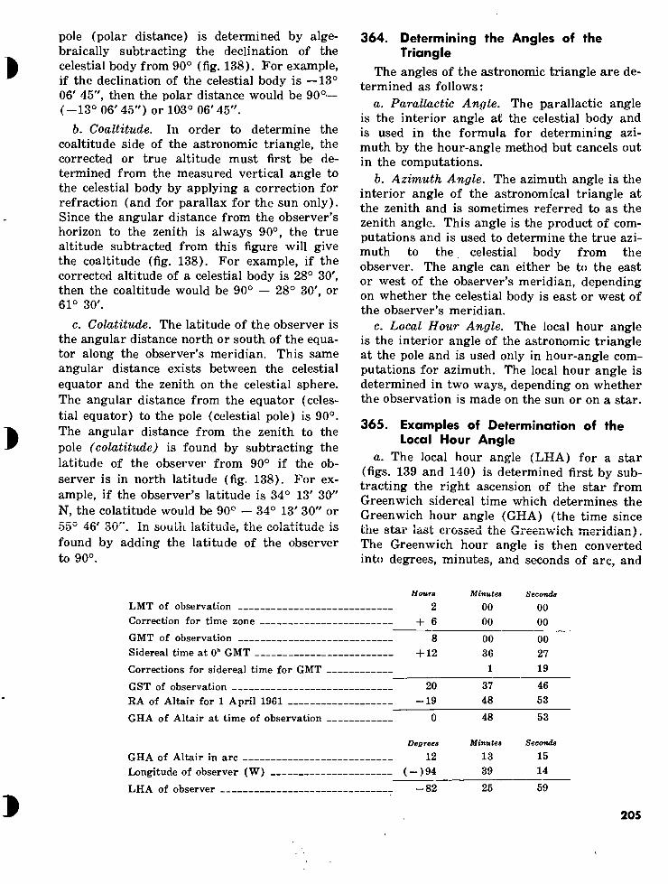
pole (polar distance) is determined by alge- braically subtracting the declination of the celestial body from 90° (fig. 138). For example, if the declination of the celestial body is —13° 06' 45", then the polar distance would be 90°— (-13° 06' 45") or 103° 06' 45".
b. Coaltitude. In order to determine the coaltitude side of the astronomic triangle, the corrected or true altitude must first be de- termined from the measured vertical angle to the celestial body by applying a correction for refraction (and for parallax for the sun only). Since the angular distance from the observer’s horizon to the zenith is always 90°, the true altitude subtracted from this figure will give the coaltitude (fig. 138). For example, if the corrected altitude of a celestial body is 28° 30', then the coaltitude would be 90° — 28° 30', or 61° 30'.
c. Colatitude. The latitude of the observer is the angular distance north or south of the equa- tor along the observer’s meridian. This same angular distance exists between the celestial equator and the zenith on the celestial sphere. The angular distance from the equator (celes- tial equator) to the pole (celestial pole) is 90°. The angular distance from the zenith to the pole (colatitude) is found by subtracting the latitude of the observer from 90° if the ob- server is in north latitude (fig. 138). For ex- ample, if the observer’s latitude is 34° 13' 3(1" N, the colatitude would be 90° — 34° 13' 30" or 50^ 4b ¿5U . in soutiL latitude, the colatitude is found by adding the latitude of the observer to 90°.
364. Determining the Angles of the Triangle
The angles of the astronomic triangle are de- termined as follows:
a. Parallactic Angle. The parallactic angle is the interior angle at the celestial body and is used in the formula for determining azi- muth by the hour-angle method but cancels out in the computations.
b. Azimuth Angle. The azimuth angle is the interior angle of the astronomical triangle at the zenith and is sometimes referred to as the zenith angle. This angle is the product of com- putations and is used to determine the true azi- muth to the celestial body from the observer. The angle can either be to the east or west of the observer’s meridian, depending on whether the celestial body is east or west of the observer’s meridian.
c. Local Hour Angle. The local hour angle is the interior angle of the astronomic triangle at the pole and is used only in hour-angle com- putations for azimuth. The local hour angle is determined in two ways, depending on whether the observation is made on the sun or on a star.
365. Examples of Determination of the Local Hour Angle
a. The local hour angle (LHA) for a star (figs. 139 and 140) is determined first by sub- tracting the right ascension of the star from Greenwich sidereal time which determines the Greenwich hour angle (GHA) (the time since me star last crossed the Greenwich meridian). The Greenwich hour angle is then converted into degrees, minutes, and seconds of arc, and
LMT of observation Correction for time zone
GMT of observation Sidereal time at 0h GMT
Corrections for sidereal time for GMT
GST of observation RA of Altair for 1 April 1961
GHA of Altair at time of observation
Hours Minutes Seconds
2 00 00
+ 6 00 00
8 00 00
+ 12 36 27 1 19
20 37 46 -19 48 53
Ö 48 53~
Degrees Minutes Seconds
12 13 15 ( —)94 39 14
GHA of Altair in arc Longitude of observer (W)
LHA of observer -82 25 59
205

the longitude of the observer is algebraically subtracted from the value of the angle, which gives the local hour angle. If the local hour angle is minus or less than 180°, this value is to be used in computations ; if the value exceeds 180° and is less than 360°, the value to be used in computations is 360° minus the local hour angle; if the value above exceeds 360°, the value to be used in computations is the local hour angle minus 360°. For example, suppose that an observation is taken on Altair from longitude 94° 39' 14" W at 0200 hours central standard time (CST) on 1 April 1961.
OBSERVER'S LONGITUDE
OBSERVER
LOCAL HOUR ANGLE
GREENWICH MERIDIAN
GREENWICH SIDEREAL TIME
GREENWICH HOUR ANGLE
A-—STAR
RIGHT ASCENSION
VERNAL EQUINOX
Figure 139. Determining the local hour angle (star) (observer in east longitude).
GREENWICH HA
HA
LONG RA
VE
Figure 140. Determining the local hour angle (star) (observer in west longitude).
b. The local hour angle for observations on the sun is determined by subtracting the longi- tude of the observer from the Greenwich hour angle (which is Greenwich apparent time plus or minus 12 hours). Example:
LMT of observation , Correction for time zone (73° 13' 43" W)
GMT of observation Equation of time at O'1 (23 July 1961) Correction for daily change for GMT
GAT of observation
GHA of sun
GHA of sun in arc Longitude of observer (W)
LHA of sun for observer
Hours Minutes Seconde
9 30 22 +5 00 00
14 30 22 - 06 22 - 01
14 23 59 -12 00 00
2 23 59
Degrees Minutes Seconds
35 59 45 -73 19 43
-37 19 58
c. In both cases in a and b above, east longi- tude is understood to be minus and west longi- tude to be plus; therefore, in subtracting east longitude, it would mean algebraically sub-
tracting a minus quantity or value. If the re- sult is negative, the celestial body is east of the observer, and, if the result is positive, the celestial body is west of the observer.
206

366. Determining Azimuth in South Latitude
If the observer is in the Southern Hemi- sphere, there are different techniques for de- termining parts of the PZS triangle and the azimuth determined will be based on the south pole.
a. The coaltitude, the colatitude, and the local hour angle are determined in the same
manner as for the observer in the Northern Hemisphere.
b. The polar distance is determined by algebraically adding the declination of the celestial body to 90° with due regard to the algebraic sign of the declination.
c. The azimuth determined will be based on the south pole. The azimuth is corrected for convergence, and 180° is either added to or subtracted from the azimuth to determine the azimuth based on grid north.
Section III. STAR IDENTIFICATION
367. General Astronomic observations for azimuth require
that the personnel engaged in performing the fieldwork be capable of readily locating and identifying any of the stars listed in the Army Ephemeris, TM 6-300-61. These stars can be identified by using either (or both) of the two identification aids discussed in paragraphs 368 and 369.
368. Star Chart The world star chart (fig. 141) based on the
equator system shows most of the brighter stars in the heavens. All of the stars listed in TM 6-300-61 are shown as well as many others which aid the observer in locating these stars. The approximate right ascension and declina- tion can be obtained from this chart and can be used as arguments to enter the chart.
369. Identification of Stars a. Proficiency in star identification is usually
based on a working knowledge of the constella- tions (star groups) and their relative locations. Starting with such familiar constellations as Orion (a kite-shaped figure on the celestial equator visible during the winter months), or Ursa Major (the Big Dipper), anyone should soon be able to lead himself from constellation to constellation across the sky. If, for example, one follows the arc of the Big Dipper on around, it will lead him directly to the star Arcturus and eventually to Spica in the con- stellation Virgo. Also, the end stars in the bucket of the Big Dipper (Dubhe and Merak, fig. 141) will lead the observer directly to Leo. These two stars are often referred to as the pointers since they are the most common
means used to locate Polaris, the North Star, when followed in the opposite direction from Leo. Figure 141, however, does not make this apparent because of distortion in the polar areas. Unfortunately, star charts, like maps, have to be printed on flat sheets of paper, and some of their relative positions are bound to be disturbed on the world star chart. Except for the stars near the celestial equator, the distor- tions on the world star chart are greater than they would be on a hemisphere star chart, but the world star chart is very useful because the declinations and right ascensions are shown graphically. The star chart indicates the relative position of the stars as viewed in the sky.
b. The first efforts should be concentrated on learning a half dozen stars in each 6 hours of the right ascension, which would be useful for observing' on or near the prime vertical or as east and west stars. For instance, there are several stars just east of the constellation Orion forming a large pentagon with the œ Canis Minor (Procyon). near the center. Greek let- ters were originally assigned in each constel- lation to the stars in order of the relative magnitude; these were only relative, but the o: stars are nearly always bright and many of them have special names. The stars are rated in order of brightness from first magnitude to fifth or sixth, which are the dimmest that are ordinarily visible without a telescope. On the star chart, the magnitude is indicated by con- ventional signs, and it is also shown in TM 6-300-61. After learning the locations of Castor, Pollux, Regulus, Alphard, Sirius, and other stars in this part of the heavens, it is
207

easy to include others coming up from the east, as the night or season advances.
370. Star Identifier The star identifier (fig. 142) based on the
horizon system is issued to all artillery units that are issued a transit or a theodolite. It assists in locating stars by providing the ap- proximate true azimuth and altitude to each given star. (It can also be used to identify stars of which the approximate true azimuth and altitude are known.) All stars shown on the star identifier are listed in the table, “Alphabetical Star List,” in TM 6-300-61 and are shown in figure 141. The star identifier consists of a base and ten templates. Nine templates are used in star identification and one template with moon and planet data is not used in artillery survey. One side of the base, marked N is used in the Northern Hemi- sphere. The other side of the base, marked S is used in the Southern Hemisphere. A template is furnished for each 10° difference in latitude from 5° through 85°. One side of each template is used for the given latitude in the Northern Hemisphere. The other side is used for the same latitude in the Southern Hemisphere. The template constructed for the latitude nearest the latitude of the observer must be used. To use the star identifier—
a. Select the proper template and correctly place it on the appropriate side of the base.
b. Determine the orientation angle as fol- lows:
(1) Estimate the watch time at which the observations are to begin.
(2) Determine the orientation angle, using DA Form 6-21 (par. 371).
c. Set the arrow on the template over the orientation angle.
d. Read the approximate true azimuth and the approximate altitude of any star on the base that is within the observer’s field of vision (stars having altitudes between 20° and 45° and azimuths between 60° and 120° or between 240° and 300° should be selected).
e. Orient the star finder so that the pointer on the template is pointing approximately to- ward true south. The stars will then appear at the approximate altitudes read from the star finder; the approximate azimuth to the star is as read from the star finder in the Northern Hemisphere or equal to the azimuth read from the star finder minus 180° in the Southern Hemisphere.
371. Use of DA Form 6—21, Computation and Instructions for Use With Star Identifier
Figure 143 shows the entries made on DA Form 6-21 for determining data in finding and identifying stars. Instructions for the use of the form are contained on the reverse side of the form (fig. 144).
Figure HI. World star chart.
(Located in back of manual)
i
«
208 «

»
• «npotxftTH ,v\'Y' '"h JS' •a?j "h f//
»»re»#
<$■
o N
/ O
% Ö
G O oos
UT1TAJ 35C LA AS AAC OÎ.Î 35°
■stf »e« G 0120
o
S8
o QSm»
\« G ■* ~9 /
& Zf
v#
jth *■«
lio % Oft tao
% Ü* VS vtf 4». w" ’‘to v\'v
% 4 >/,/ stf /,/o \<V 3W nr n
Figure 142. Star identifier.
209

COMPUTATION AND INSTRUCTIONS FOR USE WITH STAR IDENTIFIER (FU €-ttQ)
TIME ZOME
LATITUDE
OF STATION
LONGITUDE
OF STATION ?ik rs /?
SCHEDULE 1 SCHEDULE 2 SCHEDULE S SCHEDULE 4
PRESELECTED LOCAL DATE /¿>/9Pn¿/ PRESELECTED VATCH TIME «2 OOO
LONGITUDE OF STATION EAST + WEST- i> tr
LONGITUDE OF CENTRAL MERIDIAN (FROM TABLE I ON REVERSE)
EAST- WEST* a ?ot
ALGEBRAIC SUM (3) AND (4)
(FROM TABLE 11 ON REVERSE)
a /*
CORRECTION TO (4) FOR WATCH TIME (FROM TABLE III ON REVERSE 3o/
V So S'
ALGEBRAIC SUM (•) AND (9) ¥J¿2Z_
»F 10 ISL
<->
0° TO 340* MORE THAN 360*
ORIENTATION ANGLE
I* 360° (10)
REPEAT (10) (10) - 360*
Sùo
¿2JL SET POINTER OF APPROPRIATE TEMPLATE ON ORIENTATION ANGLE (SEC CUIDE ON REVEUSE)
13 NAME OF STAR Ai.ne.BAXaiu
APRX AZIMUTH OF STAR
CONVERT (13) TO MILL IF NECESSARY
APRX ALTITUDE OF STAR 37 16 CONVERT (IS) TO MILL IF NECESSARY
13 NAME OF STAR BELLfiTRl'j
APRX AZIMUTHOF STAR J5S CONVERT (13) TO MILS, IF NECESSARY
APRX ALTITUDE OF STAR 3*
1« CONVERT (IS) TO MILL IF NECESSARY
NAME OF STAR Serpee u* APRX AZIMUTH OF STAR as/ CONVERT (13) TO MILL IF NECESSARY
APRX ALTITUDE OF STAR. sr
CONVERT OS) TO MILL IF NECESSARY
13 NAME OF STAR A*CT<f*i/S
GZ APRX AZIMUTH OF STAR
CONVERT (13) TO MILL IF NECESSARY
APRX ALTITUDE OF STAR \*3 n
16 CONVERT (IS) TO MILL IP NECESSARY
DA i nr» 6.21 PREVIOUS EDITIONS OF THIS FORM ARE OBSOLETE.
4
€
210
Figure US. Entries made on front of DA Form 6-SI
«

TABLE
I
mm W < ■!
TMI ZOMI
TORT OP
Mini* OIAN
BAST L0M6
VEST LOMC
DAY OP
MONTH
TABLE II
100* 1W* 210* 140* 40*
DAY OP
MONTH
V,
TABLE III
PATCH TIME
GUIDE:
GIVEN: Time zone of area of operation. Latitude and longitude of station to nearest degree. Preselected local date of observation. Preselected watch time of observation to nearest hour.
When observation is to be made at other than preselected watch time ((2) of computation), increase orientation angle ((11) of computation) 1 degree for each 4 minutes of elapsed time after the hour or decrease orientation angle 1 degree foLeach 4 minutes of time before the hour. Select stars between 20 and 45 degrees (60 degrees if a special eyepiece is available) above horizon and within 30 degrees of a 90-degree or 270-degree azimuth (east - west line) to use the altitude method. Select four stars for each schedule, two in the east and two others in the west. Read APRX AZIMUTH and APRX ALTITUDE of stars from template of star identifier to nearest degree. When using a mil-graduated instrument, convert APRX AZIMUTH and APRX ALTITUDE to mils using table III b of TM 6-230.
LIMITATIONS: The altitude and hour-angle methods should not be used when the sur is more than 60 degrees above horizon.
RESULT* APRX AZIMUTH and APRX ALTITUDE for four schedules of four stars each at preselected watch times.
Figure Instructions for use of DA Form 6-21.
211

i
CHAPTER 22
THE ALTITUDE METHOD
Section I. GENERAL
372. General
The altitude method of astronomic observa- tion requires the solution of the astronomic triangle for the value of the azimuth angle. The three sides of the triangle are used in the computations (polar distance, coaltitude, colati- tude). The solution of this triangle has been simplified by the use of Department of the Army forms for the computations. The alti- tude method gets its name from the most criti- cal element in the solution of the triangle— the corrected vertical angle to the celestial body or the true altitude.
373. True Altitude
In the solution of the altitude method of astronomic observations, the true altitude of the celestial body must be determined. The vertical angle to the celestial body can be deter- mined by the observer but this is not the true altitude because the observer is located on the earth’s surface and also because of the earth’s atmosphere (b below). There are two correc- tions—parallax and refraction.
a. Parallax. Because the sun is so close to the earth, there is a difference between the vertical angle to the celestial body at the earth’s surface and the vertical angle to the celestial body at the earth’s center. This difference is called parallax and is equal to the angle at the center of the sun between the center of the earth and the observer. This difference is negligible on vertical angles to the stars be- cause they are so far from the earth. The cor- rection that is to be applied in artillery survey to the vertical angle observed on the sun is +07 seconds (0.04 mil) ; this is a mean value
and is always applied to altitude observations made on the sun.
b. Refraction. Owing to the density of the earth’s atmosphere, a ray of light from space is bent downward to the earth as it passes through the atmosphere. Therefore, an ob- server on the earth sees the celestial body higher in the heavens than it actually is. The refraction correction varies according to the air temperature and the altitude of the celestial body observed. The refraction correction is always minus and is obtained from the ephe- meris by using the air temperature at the sta- tion and the observed vertical angle to the celestial body.
374. Required Field Data The field data which must be obtained to de-
termine direction by the altitude method of astronomic observation are as follows:
a. Mean horizontal angle from an azimuth mark to the celestial body (sun or star).
b. Mean vertical angle to the celestial body. c. Date and mean time of observation (cor-
rect to nearest 5 min). d. Air temperature. e. Geographic coordinates of station. /. UTM (UPS) coordinates (whenever pos-
sible) . g. Approximate azimuth to the azimuth
mark.
375. Selection of Astronomic Observation Station
When other survey operations do not deter- mine the location of the point at which astro- nomic observations must be made, a point with known geographic coordinates should be se-
212 «

lected. If that is not possible, a point with known grid coordinates should be selected. If neither of these is possible, a point should be
selected which can easily be located on a large- scale map; i.e., a point which is easily identi- fiable both on the map and on the ground.
Section II. DETERMINING FIELD DATA
376. General Field data for determining azimuth by astro-
nomic observation consist of the horizontal angle between an azimuth mark and the ob- served celestial body, the vertical angle to the body (altitude method only), the time of the observation, the temperature at the time of the observation (altitude method only), and the location of the observing station in both geographic and grid coordinates.
377. Determining Horizontal and Vertical Angles
The instruments used to observe celestial bodies are the T16 theodolite or the T2 theo- dolite. Angles are determined in much the same manner as in any other method of sur- vey; i.e., the angle is determined by comparing the mean pointing on one station with the mean pointing on another. Since celestial bodies appear to be moving, the technique of pointing is slightly modified. Also, since the sun presents such a large target, special tech- niques must be employed to determine its center.
378. Use of the T16 Theodolite in Astronomie Observations
a. The T16 theodolite is equipped with a solar circle on its reticle (fig. 145). This per- mits an observer to view the sun in such a manner that the vertical and horizontal cross- lines of the instrument are directly over the center of the sun. The initial pointing on the azimuth mark is made with the telescope in the direct position. The telescope is then pointed toward the sun. The sun is placed in the solar circle and tracked by using both the horizontal and vertical tangent screws. When the sun is as nearly centered in the solar circle as possible, the observer announces TIP, levels the collimation level bubble, and reads the ver- tical and horizontal circle readings. The tele- scope is then plunged and the process repeated with the telescope in the reverse position. With the telescope still in the reverse position,
the final pointing is made on the azimuth mark, the mean data can now be determined.
Caution: Do not view the sun directly through the telescope unless the sun filter has been affixed to the eyepiece.
Figure 1A5. T16 theodolite reticle with solar circle.
b. Stellar observations with the T16 theodo- lite are performed as outlined in a above except that the intersection of the single vertical crossline and the horizontal crossline is used rather than the solar circle. This intersection is placed just ahead of the apparent path of the star. The star then moves into the inter- section by its own apparent motion, at which time the operator announces TIP.
379. Use of the T2 Theodolite in Astronomic Observations
a. The T2 theodolite is not equipped with a solar circle for pointing on the center of the sun (fig. 146). To achieve measurements to
213

the center of the sun, measure the angles to one side of the sun with the telescope direct and then to the other side of the sun with the telescope in the reverse position. The resulting mean angle is the angle to the center of the sun. This method of determining the center of the sun is called the quadrant method and can be used either when the sun is viewed directly through a sun filter or when the image of the sun is projected onto a card held to the rear of the eyepiece of the telescope. To determine the correct quadrant in which to place the image of the sun, first determine the direction the sun is moving. If the motion of the sun is through the first and third quadrants (from first to third or from third to first) as viewed through the telescope or on the card, the image of the sun should be placed in the second and fourth quadrants. If the motion of the sun is through the second and fourth quadrants (from second to fourth or from fourth to second), the image of the sun should be placed in the first and third quadrants. The leading edge of the sun is always tracked with one of the crosslines and tangency is obtained with the other through the sun’s movement. Point- ings on the sun with the T2 theodolite are shown in figures 147 and 148. If the sun is placed tangent to the vertical crossline, it is brought into tangency with the slow horizontal
motion. If the sun is placed tangent to the horizontal crossline, it is brought into tangency with the slow vertical motion. Because of the double vertical crossline, the sun must be placed in one of the two quadrants separated by the single vertical crossline.
b. For stellar observations, the T2 theodo- lite is used in the same manner as discussed in paragraph 378b for the T16 theodolite.
MEAN HORIZONTAL ANGLE
HORIZONTAL
MEAN MEAN CENTER OF SUN VERTICAL ANGLE
HORIZONTAL
Figure 1^6. Method of observing to determine the mean center of the sun.
i
G
PM TEL DIR
AM TEL REV
TE EV Dl
APPARENT NOON
Figure 1A7. Quadrants used in Northern Hemisphere for observation with Wild T2 theodolite (direct observation with dark filter).
214 €

APPARENT J NOON
TEL DIR
TEL REV
TEL REV
TEL DIR
AM
MOVEMENT ON CARD
Figure H8. Quadrants used in Northern Hemisphere for observation with the Wild T2 theodolite (card method).
380. Time
a. The times at which pointings are made on the sun or a star are read and recorded to the nearest second for both methods of astro- nomic observation. With the altitude method, it is not necessary to know time to this ac- curacy, but recording the time to the nearest second will give the recorder additional prac- tice in reading and recording time for the hour-angle method. Time recorded to the nearest second will also provide survey person- nel a means for detecting errors from examina- tion of field data. When the altitude method is used for observing a star, it is necessary to know only the date of observation. When the altitude method is used for observing the sun,
it is necessary to know only the date and time of observation with an error of not more than 5 minutes. Time correct to 5 minutes can- be obtained from the message center clock.
b. The watch used by the artillery surveyor to measure time for astronomic observations should be a reliable watch with a sweep second hand.
c. Watch times are based on standard time zones, each of which covers a portion of the earth. In a zone of operations, survey per- sonnel using astronomic observations must know the time zone on which their watch time is based. The time zone on which a watch is based can be determined from the message cen- ter. (Time zone corrections are given in table I.)
Table I. Time Zone Corrections, Local Mean Time to Greenwich Mean Time
Time Zone
z . A B . C . D . E . F . G . H I _ K . L . M
Correction (honre)
0 - 1 - 2 - 3 - 4 - 5 - 6 - 7 - 8 - 9 -10 -11 -12
Time Zone Correction (hours)
z . N O . P . Q - R . S - T . U V . w X . Y .
+ + + + + + + + 8 + 9 + 10 + 11 + 12
Note. Time zone Q corresponds to eastern daylight saving time. Time zone R corresponds to eastern standard time and central day- light saving time. Time zone 5 corresponds to central standard time and to mountain daylight saving time. Time zone T corresponds to mountain standard time and to Pacific daylight saving time. Time zone U corresponds to Pacific standard time.
» 215

381. Time of Observation
Because of the apparent motion of a celestial body, the watch time at which each pointing is made on the celestial body should be read and recorded to the nearest second. To obtain the accurate time of observation the instrument operator announces “Ready” a few seconds be- fore the star is at the intersection of the cross- hairs or before the sun is tangent to the cross- hairs. He announces “Tip” and stops tracking at the exact instant of tangency. The recorder reads and records the time corresponding to the exact second that the operator announces “Tip.” The times corresponding to the direct (first) reading and the reverse (second) read- ing are meaned. This is the mean time of observation.
382. Temperature
For the altitude method, it is necessary to know the air temperature at the time of ob- servations in order to determine a refraction correction. The temperature should be deter- mined within an accuracy of 5° F. The tem- perature can be determined by using the psychrometer in a surveying altimeter, or it can be obtained, by prior arrangement, from a meteorological or weather section. In an artillery unit, the temperature can be obtained from the thermometer used to obtain powder temperature in a gun section.
383. Geographic Coordinates of the Astronomic Observation Station
The geographic coordinates (latitude and longitude) of the astronomic observation sta- tion must be known for the hour-angle method. The latitude of the station must be known for the altitude method. For both methods, it is desirable to know the geographic coordinates for the computation of convergence. (The geographic coordinates of trig points can usually be obtained from trig lists issued by the Corps of Engineers.)
a. If the geographic coordinates of the sta- tion are not known, they are determined, if possible, by measuring, from a large-scale map. If the grid coordinates of the station are known, they should be used to accurately plot the location of the station on the map. If the
grid coordinates of the station are not known, the location of the station must be plotted on the map by careful map inspection.
b. If the geographic coordinates of the sta- tion are not known and a large-scale map is not available but the accurate grid coordinates are known, the geographic coordinates must be determined by conversion of the grid coordi- nates (ch. 27).
c. If the geographic coordinates cannot be determined by any means, azimuth cannot be determined by the altitude or hour-angle method of astronomic observation.
384. UTM Grid Coordinates of the Astronomic Observation Station
The UTM grid coordinates of the astronomic observation station should be known in order to compute convergence through both geographic and UTM grid coordinates.
385. Approximate Azimuth to Azimuth Mark
The approximate azimuth to the azimuth mark should be determined and recorded to detect large errors in computations. This azi- muth may be determined by using an M2 com- pass or the compass of an aiming circle or by scaling the azimuth from a large-scale map.
386. Recording Field Data Field data for astronomic observations are
recorded as discussed in paragraph 206.
387. Determination of Final Azimuth
a. Fifth-order astronomic azimuths are determined by using the T16 theodolite. To achieve a fifth-order astronomic azimuth, ob- serve and compute at least three sets of obser- vations—each set, one position. Mean the azi- muths and reject any set which varies from the mean by more than 0.3 mil. At least two sets must remain and be remeaned to deter- mine final azimuth. The considered accuracy of a fifth-order astronomic observation is ± 0.3 mil.
b. Fourth-order astronomic azimuths are determined by using the T2 theodolite. To achieve a fourth-order astronomic azimuth, ob- serve and compute at least three sets of obser-
216

vations—each set one position. Mean the azi- muths and reject any set which varies from the mean by more than 30". At least two sets must remain and be remeaned to determine final azimuth. The considered accuracy of a fourth-order astronomic observation is ±30".
388. Azimuth Checks and Improvements Azimuths may be checked and improved by
using the following methods : a. A final azimuth determined from observa-
tions on the sun before noon may be checked and improved by determining another final azimuth on the sun in the afternoon. The same observer’s position and azimuth mark are used. The two final azimuths are meaned.
b. Another method of improving or check- ing an azimuth is to use an east and a ivest star and mean the final azimuths.
389. Limitations a. For best results with the altitude method,
the celestial body is observed within 30° (azi- muth) of the prime vertical (60° to 120° and 240° to 300° in azimuth). The vertical angle is the critical element in the altitude method but an error in vertical angle has less effect on the final azimuth throughout this band. A celestial body should not be observed at alti- tudes less than 20° because the refraction cor- rection is very great.
b. Vertical angles of less than 20° have a large and uncertain refraction correction. (A 5° vertical angle at 80° F. has a refraction correction of 9' 06".) Refraction corrections for vertical angles less than 20° are not tabu- lated in TM 6-300-61. Do not attempt to ob- serve a celestial body above 45° without special astronomical equipment.
Section III. COMPUTATIONS
390. Computation of Astronomic Azimuth Computations for determination of astro-
nomic azimuth by the altitude method are entered on DA Form 6-11 (Computation- Astronomic Azimuth by Altitude Method, Sun or Star (figs. 149 and 150)). This astronomic azimuth can be converted to grid azimuth by using DA Form 6-20 (Computation-Conver- gence (figs. 151 and 152) (par. 392)).
391. Use of DA Form 6-11 a. Determination of azimuth by the altitude
method depends on solution of the astronomic (PZS) triangle when the three sides—polar distance, colatitude, and coaltitude—are known (par. 363). DA Form 6-11 provides a con- venient step-by-step means for computing the azimuth angle (par. 3645) required. The hori- zontal angle measured from the azimuth mark to the celestial body observed is applied to the computed azimuth during the last steps to de- termine true azimuth to the mark. The formula solved and a guide for use of the form are shown on the back of the form.
5. Entries are made on the form as shown in figures 149 and 150. The data given below are taken from the field notes.
(1) Station. BnSCP. (2) Azimuth mark. Station Oak.
(3) Latitude. 30° 16' 21" N. (4) Longitude. 97° 36'42" W. (5) Area. Round Hill. (6) Approximate azimuth to the azimuth
mark. 3650 mils. (7) Local date. 29 May 1961. (8) Temperature. 94° F. (9) Watch correction. 13 seconds slow
( +138). (10) Mean time of observation. 15h 22m
12s (S). (11) Mean vertical angle. 477.3 mils. (12) Mean horizontal angle. 954.8 mils.
c. Under certain conditions, auxiliary com- putations are required to determine data for entry on DA Form 6-11. Spaces for these com- putations are provided on the reverse side of the form.
(1) When observations are made with a mil-graduated instrument, latitude and longitude of the observation sta- tion are converted to mils in the space provided.
(2) When the sun is the celestial body observed, an auxiliary computation for declination at Greenwich mean time of observation is necessary to
217

COMPUTATION-ASTRONOMIC AZIMUTH DY ALTITUDE METHOD. SUN OR STAR TABLE NRS REFER TO TM 6-300. 19. 6l
30 °| l6'i 97 "136 te "¿fro»1.1. U030^ I »,‘¿9 MAY 6l
SUN OR STAR NAME AND NR (TAfiLE 9) SUV
LCNGITUDt OP STATIOM ffSk OAK
TlMPCOATURI / 9^
MC AM WATCH Tlal OP OCSIRVATIOM
WATCH CMRICTIOH
3.5 ig 112 ' 13
hi ml I
9. 936 I 326
9- 950 i 573 I-
Q, flfig . fiOO
I r
ALOCUAK SUM Ml AMO III 22_^
TlMl ZOMC CORRICTIOM i 6 LOC COS (20)
ALOCMAK SUM (J) AMD <4>
a, 66l|-371 21 22 , 35 3;
CRCINWICH DATE . 29 KM ..61 24 00 00 24 00 00 24 00 00 9 659 I 283
CRIKNWICH MEAN TIME (GMTI 21 22 ,35
2; 1 3?
77 , 3 9 - 772 i 381s
1)0)4. IQ.COO MM
PARALLAKSUH MLY) + 07 SECONOS OR 4Q.W MILS +.0L
•9 - 772,381s 9l 886,192
POR SUM. (7)4.(ll POO STAR. REPEAT 17) 77 i 34 ANGLE HAVING LOG ( .1 02)
IIPIACT4N ITAELC I OR >>MIL1> 0 , 52 7 ,05 ,7
(•)—<10) TRUC ALTITUDE (h)
rr 76 , 82 85 %8
Liur-A.iMi «»«►•iiSoJ C«I*TI* TKâ» 11*1 IIAItllMI
j» UTiim »nt »MoÜjCjl-mi H mm
Ik 111 i ‘s 6U |00 ! o
i h
tfww OR isooje^ 16 00 tus
REPEAT (12) WITH SIGH REVERSED
ALGERRAIC SUM«II) AHO MO £>12 85 % tua.)-"-
Ils ,11 , Is ls9 ,88 16
MEAN HORIZONTAL ANGLE
,52 9 15i) i 8
H h
H h
UL 76 Tse
17 (11) - (U) S ASTRONOMIC AZIMUTH TO MARK IsO .33.8 ■+—+■
16 [(171 OP CONVERSION TO MILS 1 NORTH +
¡TOMP ON REVERSE IP USMC MILSJ SOUTH @ 5 ai.,3^ 38 ,17
ALGERRAIC SUMII7) AW Ml) 22 29 51
Sun
«L
JJt-Oè REPEAT MSI 12 3* ,52 SURTRACT SMALLER, (20) OR OIL
PROM LARGER. (21) OR (20),
SIGN ALWAYS
PLUS 11 |Hs i 76
■fc IP IS) IS. ( + I AMD LI IS THAN 24 NRS ( + )AW MORE THAN 24 HRS
■99 ' ?6 l +
bA/Dr..6-i1
GREENWICH DAT! (4) I Si
LOCAL DATE LOCAL DATE-PI OAT LOCAL DATE - 1 OAT
Stn Oak SAME AS O) >“ 24 HRS
HRS - (I) SMITH JOBSS RKPLACKa IDITtOM OP 1 SCP 1*. WHICH IS OBSOLETE
4—H
H 1-
iim i
SHIE^ OP 2*hiit>
Figure H9. Entries made on front of DA Form 6-11 for computing true azimuth from observations on the sun (altitude method)

219
AUXILIARY COMPUTATION FOR APPARENT DECLINATION OF SUN
AT GREENWICH DATE AND GMT
\ ORCtMalCH DATE [«> OF COMPUTATION] 29 MAT 6l
CMT {HOURS ANO MINUTIS IN I«) OF COMPUTATION]
3 NUMtERS OF HOURS IN OI X *0
UMBER OF MINUTES IN IT)
5"
LOC OF CONSTANT
in + m + m
(111 CONVERTED TO MINUTES AND SECONDS OR (II) IN MILS [USE SICNOF (♦)]
2L. X60
1260 22
1202
22^
2 -75 ? 107 1888
p: urejra 6l8 4 I Í6375
o' ^BSiSsae
&
2%5
k 2 ;
^ ^ 185 I »*8
X60
els 4 I 16375 X
-h
X60
x
618 4 1 X
6375
CONVERSION TO MILS COMPUTATION (USE TABLE III b OF TM 6-230)
*1 IN HUNDREDS OF _2L
_l6
JX
36 ,1)2 '
00 loo 21)11)1)
8189 1178
20
101
J5J32.
SUM OF mi THROUGH IHI
[ENTER IM (III ON FRONT!
ANO ON DA FORM 1-20 I
ill? I 81 33 33.
2 1 96
X 7d
■ 00
5 138 11?
GIVEN: Time zone of area of operation.
FIELD DATA: Latitude and longitude of station. Approximate azimuth to azimuth mark and to sun or star (sketch). Sun or name(s) and number(s) of selected star(s). Local date of observation. Temperature at time of observation. Mean watch time of observation and watch correction. Horizontal clockwise angle from azimuth mark to sun. Observed altitude of (vertical angle to) sun or star.
GUIDE: j Enter observed field data in block marked. E 1 When using a mil-graduated instrument,--
a. (7) through (22) of computation are computeo using hundredth-mil values. b. (6) through (14) of AUXILIARY COMPUTATION are computed using hundredth-
mil values. c. (2) through (9) and (11) through (17) of CONVERSION TO MILS COMPUTATION
are computed using hundredth-mil values. d. (23) through (37) of'computation are computed using tenth-mil values.
Value in (37) should be about equal to approximate azimuth to azimuth mark. Continue computations using DA Form 6-20 to obtain the UTM grid azimuth.
LIMITATIONS: This form should not be used when accuracies greater than fourth-order are required. The altitude method should not be used when the sun or star is--
a. Less than 20 degrees or more than 60 degrees above horizon. b. More than 30 degrees from a 90-degree or 270-degree azimuth (east-west line).
RESULTS: A value of astronomic azimuth for each set of observations.
FORMULA:
Cos 1/2 As /Cos a Cos (a-p) V Cos Lat Cos h
A - astronomic azimuth of sun or star measured east or west of meridian,
s = 1/2 sum of polar distance, latitude, and true altitude,
p ? polar distance of celestial body.
Lat s latitude of station. ,
h = true altitude of celestial body.
690 996677
Figure 150. Auxiliary computations and instructions on back of DA Form 6-11.

determine the value to be entered on line 12 of DA Form 6-11. The Army Ephemeris (table 2) tabulates data for declination of the sun at 0h GMT for each day of the year and the daily change from one day to the next. An interpolation is performed to deter- mine the fraction of daily change cor- responding to the difference between 0h GMT and GMT of observation. A space is provided on the reverse side of the form for this interpolation. The following formula is solved:
Change in declination = GMT of observation x daily change (seconds or mils)
1,440 (minutes in a day)
392. Use of DA Form 6-20 a. Computation for determining the conver-
gence (difference between grid north and true
north) for the observer’s location is performed on DA Form 6-20 (figs. 151 and 152) from geographic and, if possible, from grid coordi- nates. This convergence is algebraically added to the astronomic (true) azimuth computed on DA Forms 6-10, 6-10a, and 6-11 to convert that azimuth to grid azimuth.
b. The data necessary to compute the con- vergence are the geographic and grid coordi- nates of the observer’s location. The con- vergence for the problem computed in figures 151 and 152 is computed from the following data:
(1) Station. BnSCP. (2) Azimuth mark. Station Oak. (3) Latitude. 30° 16' 21" N. (4) Longitude. 97° 36'42" W. (5) UTM grid coordinates (nearest 100
meters). (633600-3349600).
220

COMPUTATION - CONVERGENCE (ASTBOHOMIC AZIMUTH TO UTM GRIL AZIMUTH) (T*bi» Numb0r* Mmfmr to Tit Ä - 300 - 19 SX )
( r* 6-no)
Bn SCP
AZIMUTH MARK
mmm OMC
LONGITUDE OP STATION X7.35,32
E UTM GRID
ZONE EASTING OP STATION
633 . 600
LATITUDE OP STATION 1 I
NORTHING OP STATION 3 i 3^ , 600
! 1
17 ,35 ,32 LONGITUDE OP STATION EASTING OP STATION
633 , 600
LONGITUDE OP CENTRAL MERIDIAN
(PROM TABLE ON REVERSE) 17 [60 I oo 500.000
MORE THAN (2)
LESS THAN (2)
(1) -(2)
(2) —- ( I)
17 |3ñ 132,
^ ■«
MORE THAN (12)
LESS THAN (12)
(11) - (12)
(12)-01)
133 |60Q
133 I 600- IP (1) IS IN DEGREES, USE (fl ) OP CONVERSION COMP ON REVERSE IP (I) IS IN MILS. REPEAT (3) 2k .66
REPEAT (12) WITH DECIMAL
POINT MOVED LEPT SIX PLACES o • 133 i 600
392| 3^5 1 <» 12S| 8o6
LOG SIN LATITUDE OP STATION 9 . 702, 5^ LOG OP PUNCTION XV
(TABLE 6} UfiazkL jr^ 66k
1 3j i(fli| 67fL 1, . ogly, 689
NUMBER HAVING LOG (7) «
PIRST TERM IN SECONDS OR MILS
T
SECOND TERM (TABLE 8 OR
8*MJLI. USE (2) AMD LATITUDE)
.12 M LOG CONVERSION
SECONDS TO MILS 776 9 3:575 00
IP (I) IS IN DEGREES, REPEAT (17)
IP (1) IS IN MILS, USE (17) + (18) L 095i 2k5
(•14(9). COMVCRCCHCC M SCCONOtOK MS.»
«MCM tTATIOM ts IM HOBTH LATITUDI AMO..
MVZtTLOMC IMCASTLOMG IP(H il. no i». no n. MOBC TMAM (S 4 LIISTMAMU) - 4
WMCM tTATIOM IS M SOUTH LATITUD« AMD.. M VIST LOMO W CAST LONG
IF (U IL no is. no)is. MORBTHAHI» - + LOS TMAM <71 + -
NUMBER HAVING LOG (IP) «
PIRST TERM IN SECONDS OR MILS 12 . SECOND TERM (TABLE 7, USE
(M) AMD MORTHIMG) 0 .00
12
(20)-(2I)-COHVCCGCMCC IM SCCOMOS Q MILS •HIM STATION IS IN MOUTH LATITUM IF (11) IS. 127) IS. KOBE THAN (12) — LIU THAN (1» +
VMCN STATION ISM SOUTH LATITUDE IF <H) IS IP) IS. MOB! THAN (12) + LIU TMAM (12) —
¿5.
12 -^5
IP (10) AND (22) DIPPER BY MORE THAN / C4" \ REDETERMINE COORDINATES AND RECOMPUTE ALL COMPUTATIONS 1.0.02 MJ
CONVERGENCE IP (1) IS IN DECREES. USE (18) OF CONVERSION COMP ON REVERSE If (1) IS IN MILS. REPEAT (22)
+
ÊL ,12 .1*5
SUMMARY OF ASTRONOMIC AZIMUTHS AND COMPUTATION OF UTM GRID AZIMUTH
MEAN (SIGN 4- )
CONVERGENCE REPEAT (23)
ALGEBRAIC SUM OP (31) AND (32)
= GRID AZIMUTH TO MARK
ASTRONOMIC AZIMUTH TO AZIMUTH MARK
UP i 33, 8
UOj + 3
8
121 V
UP j 211 k
SMITH
NOTEBOOK
REFERENCE U-B-6
JunRS
ROUND ** f u.
SHEET ^ OF ^ SHEETS
29 MAY 1961
DA ,^6-20 REPLACES DA FORM 6-20, 1 OCT 5?; AND DA FORM 6-2N, 1 SEP 52, «HICH ARE OBSOLETE.
Figure 151. Entries made on front of DA Form 6-20 for converting true azimuth to correct grid azimuth.
221

TABLE - CENTRAL MERIDIAN OF UTM GRID ZONES
ZONE DECREES NR W LONG
MILS V LONG
ZONE NR
DEGREES « LONG
MILS W LONG
ZONE NR
DEGREES E LONG
MILS E LONG
ZONE NR
DEGREES E LONG
MILS E LONG
177 3146*67 16 87 1S46.67 S3.33 93 1553.33
171 3040.00 17 81 1440.00 32 160.00 47 1766.00
16S 2933.33 18 75 1333. 33 33 15 266.67 105 1866.67
159 2826.67 19 69 1226. 67 21 373.33 49 111 1973.33
153 272a 00 20 63 112a oo 35 27 480.00 50 117 208040
147 2613.33 21 57 1013.33 36 33 586.67 51 123 2186.67
2506.67 906.67 37 693.33 52 129 2293.33
135 240a00 23 800.00 38 45 800.00 S3 135 240a00
2293.33 24 39 693.33 39 141 2506.67
10 123 2186.67 586.67 1013.33 147 2613.33
117 208a 00 27 63 maoo 56 153 2720.00
12 111 1973.33 27 21 373.33 4:.' 13 105
14 99
93
1866.67
p76aooS~ 15 266.67
ua oo ir
1236.67
133Í.33
57 159 2826.67
58 165 2933.33
144a00 59 171 304a00
1653.33 30 53.33 45 87 t$46.67 60 177 3146.67
CONVERSION COMPUTATION
DEGREES. MINUTES. AND SECONDS TO SECONDS ÎT TT
SECONDS TO DEGREES. MINUTES. AND SECONDS
REPEAT (3) 9 REPEAT <22) OF COMPUTATION
NUMBER OF DEGREES |N(I) 10 NUMBER OF TIMES 3600 DIVIDES INTO (9) s NUMBER OF DEGREES IHJ9]
11 REPEAT (9)
(2) X 60 12 NUMBER IN (10) X 3600
NUMBER OF MINUTES IN (1) 13 (11)— (12)
(3) + (4) 14 NUMBER OF TIMES 60 DIVIDES INTO (13) s NUMBER OF MINUTES IN (9J
X60 15 REPEAT (13)
(5) X 60 16 NUMBER IN (14) X 60
NUMBER OF SECONDS IN (1) 17 <15)-(16)sNUMBER OF SECONDS IN (9)
r + CONVERGENCE lgl (ENTER IN (23) OM FRONT)
(6) + (7 ) ENTER IN (4) ON FRONT
GIVEN: UTM grid zone of area of operation. UTM grid coordinates of station to nearest meter. Latitude and longitude of station to nearest second or one*hundredth mil (DA Form 6-10, 6-10a, or
6-11). A value of astronomic azimuth for each set of observations (DA Form 6-10, 6-10a, or 6-11).
GUIDE: When using a mil-graduated instrument, - - a. (1) through (5), (7) through (10), and (20) through (22) of computation are computed using
hundredth-mil values. b. (6) and (24) through (33) of computation are computed using tenth-mil values.
Compare (10) and (22) and, if they differ by more than 4 seconds or 0. 02 mils, redetermine coordinates and recompute all computations.
LIMITATIONS: This form should not be used when accuracies greater than third-order are required.
RESULTS: A value of UTM grid azimuth from the mean values of astronomic azimuth and the grid convergence at the station.
FORMULAS: UTM grid azimuth = Astronomic azimuth * convergence. USING UTM GRID COORDINATES; Convergence = (XV)q - (XV
(XV) = a variable function based on latitude of station (obtained from TM 6-300-19 , “Army Ephemer is for 19 ").
q = 0.000 001 times the distance in meters from central meridian of UTM grid zone to station.
(XVOq3 = second term of convergence computation (obtained from TM 6-300-19 , "Army ehe- rner is for 19 ").
USING GEOGRAPHIC COORDINATES: Convergence - (XU)p + (XUI)p3
(XU) = 10,000 times sine of latitude of station. p = 0.0001 times distance in seconds or mils of arc from central meridian of UTM grid
zone to station. (XIII)p3 s second term of convergence computation (obtained from TM 6-300-19 , "Army Ephe-
meris for 19 ").
Figure 152. Auxiliary computations and instructions on back of DA Form 6-20.

CHAPTER 23
HOUR-ANGLE METHOD
Section I. GENERAL
393. General
a. The hour-angle method of astronomic ob- servation also requires the solution of the astronomic triangle. The parts of the triangle that are used are the polar distance, the colati- tude, and the local hour angle (two sides and the included angle).
b. The local hour angle is determined from the time of observation and is directly pro- portional to the azimuth of the body ; therefore, it is extremely important that it be correct to the nearest 1 second. The hour-angle method can be used any time the altitude method is used, provided time is correct to the nearest second.
c. The hour-angle method can be used when the celestial body is below 20° altitude; how- ever, as the line of sight approaches the obser- ver’s horizon, an error (horizontal refraction) may be introduced which cannot be corrected.
d. If there is no celestial body within the
desirable limits for the altitude method, then a celestial body which is as near as possible to the limits should be selected and the hour-angle method used.
394. Required Field Data a. The field data required for the hour-angle
method are slightly less than the altitude method. The data needed to compute the azi- muth by the hour-angle method are as follows :
(1) Mean horizontal angle from azimuth mark to celestial body.
(2) Mean time of observation correct to nearest second (10“ for Polaris).
(3) Geographic coordinates of observer’s station and when possible UTM (UPS) grid coordinates to nearest 100 meters.
(4) Approximate azimuth to azimuth mark.
b. The vertical angle is not needed for the hour-angle method.
Section II. DETERMINING FIELD DATA
395. Determining Angles (Hour-Angle Method)
Except for the method of pointings (pars. 379 and 380) horizontal angles are determined for the hour-angle method in the same way that they are determined for the altitude method. (A set of observations for the hour- angle method consists of determining horizon- tal angles—one position for theodolites.) 396. Pointings on Celestial Bodies
(Hour-Angle Method) The techniques of pointing for the altitude
method (pars. 379 and 380) may be used for the hour-angle method. Alternate methods of pointing for the hour-angle method are given in paragraphs 398 and 399.
397. Pointings on a Star (Hour-Angle Method)
When observing a star for the hour-angle method, place the vertical crossline just ahead of the star so that the star will move toward the crossline. Place the horizontal crossline approximately on the star. Let the crosslines
223

remain stationary. Just before the vertical crossline is over the star, announce “Ready”. At the instant that the crossline is over the star, announce “Tip”. (The recorder reads and records the watch time corresponding to the exact instant that the instrument operator announces “Tip”.)
398. Pointings on the Sun (Hour-Angle Method)
When observations are made with the T16 theodolite, the procedures for pointings on the sun are as described in paragraph 379a. When the T2 theodolite is used, either the quadrant method discussed in paragraph 380 or the fol- lowing procedures are used : Place the vertical crossline just ahead of the leading edge of the sun in the direct position and just ahead of the trailing edge of the sun in the reverse posi- tion so that the sun will move into tangency with the vertical crossline. Place the hori- zontal crossline so that it approximately bisects the sun. Let the crosslines remain stationary. Just before tangency, the observer announces “Ready”. At the instant of tangency, he an- nounces “Tip”. (The recorder reads and re- cords the watch time corresponding to the exact instant the observer announces “Tip”.) Using this method, obtain tangency first with the leading edge of the sun (telescope direct) and then with the trailing edge of the sun (telescope reversed).
399. Time When the hour-angle method is used, the
time is not only recorded to the nearest second, but it must be correct to the nearest second (nearest 10 seconds for Polaris). The method for obtaining the correct time from radio time signals is explained in detail in TM 5-234. The watch correction should be obtained before and after the observations. If there is a difference, the mean time of each observation must be de- termined by using the corrections.
400. Coordinates The methods of determining geographic and
grid coordinates and their use are discussed in paragraphs 384 and 385.
401. Approximate Azimuth Mark The methods of obtaining the approximate
azimuth to the azimuth mark are discussed in paragraph 386.
402. Records of Field Data The method of recording field data for
astronomic observations (hour-angle method) is discussed in paragraph 206.
403. Techniques The techniques for the hour-angle method
are the same as for the altitude method (par. 387) except the vertical angle is not measured.
Section III. COMPUTATIONS
404. Computation of Azimuth by the Hour-Angle Method
Because of the difference in solar time and sidereal time, a different form must be used when the azimuth is computed using a star than when it is computed using the sun. The form used for the hour-angle method, sun, is DA Form 6-10. This form is discussed in paragraph 405. The form used for hour-angle method, star, is DA Form 6-10a. This form is discussed in paragraph 406.
405. Use of DA Form 6—10 a. Determination of azimuth by the hour-
angle method depends on solution of the astro-
nomic (PZS) triangle when two sides and the included angle are known. The two sides re- quired are polar distance (par. 363a) and colatitude (par. 363c). The included angle is the local hour angle (pars. 364c and 365). DA Form 6-10 provides a convenient step-by-step means for computing the azimuth angle (par. 3645) required, when the sun is the celestial body observed. The horizontal angle measured from the azimuth mark to the sun is applied to the computed azimuth during the last steps, to determine true azimuth to the mark. The formula on which the form is based and a guide for the use of the form are shown on the reverse side.
b. Entries made on DA Form 6-10 are
224

shown in figures 153 and 154. The data given below are taken from the field notes—
(1) Station. Dunce. (2) Azimuth mark. Water tower. (3) Latitude. 34° 39' 48" N. (4) Longitude. 98° 24' 18" W. (5) Area. Gunnery Hill. (6) Approximate azimuth to azimuth
mark. 4,300 mils. (7) Local date. 12 March 1961. (8) Watch correction. 1 second fast
(-01«). (9) Mean time of observation. 08h 49m
48« (S). (10) Mean horizontal angle. 4,085.5 mils.
c. Spaces are provided on the reverse side of DA Form 6-10 for the auxiliary computations required.
(1) Declination of the sun at Greenwich mean time of observation is com- puted as explained in paragraph 391c (2) for entry on line 18 of the form.
(2) Conversion of latitude and longitude to mils is performed on the reverse side, when required.
(3) A space is provided for conversion of time to arc, for entry on line 12 of the form.
406. Use of DA Form 6—10a a. DA Form 6—10a is used to compute azi-
muth by the hour-angle method when a star is the celestial body observed. The form is used to solve the astronomic (PZS) triangle in the same manner as DA Form 6-10. The steps performed are the same except that the local
hour-angle is determined from sidereal time and right ascension instead of from apparent time. Declination of a star is obtained from the Army Ephemeris for Greenwich date of observation, eliminating the auxiliary compu- tation required when the sun is observed.
b. Entries made on the form are shown in figures 155 and 156. The data given below are taken from the field notes. The example is from a fourth-order observation.
(1) Latitude. 34° 39'48" N. (2) Longitude. 98° 24'18" W. (3) Approximate azimuth to mark. 240°. (4) Local date. 11 March 1961. (5) Azimuth mark. Water tower. (6) Station. TS-7. (7) Star. Polaris. (8) Mean time of observation. 19h 58m
36« (S). (9) Watch correction. 25 seconds slow
(+ 25s). (10) Mean horizontal angle. 114° 34' 20". (11) Area. Gunnery Hill.
c. Spaces are provided on the reverse side of the form for certain auxiliary computations required.
(1) Conversion of latitude and longitude to mils, when required.
(2) Conversion of time to arc, for entry on line 12 of the form.
407. Grid Azimuth DA Form 6-20 determines the convergence
to be applied to the astronomic azimuth com- puted on DA Forms 6-10 and 6-10a.
225

226
COMPUTATION - ASTRONOMIC AZIMUTH BY HOUR - ANGLE METHOD. SUN
°l ' I , "AJ LOttCITUOE f* 0 l_t ~ " I I .raí *i " TLOCAL Z
3^ i 391 ^8 T] °>i'»’»» ^8 ,2h i 18 ¿1,o»»^ ^-300 <“»■ 12 MAR 6l
TABLE HRS REFER TO TM t- 300 . 19. 6l SUN
WT DOUCE
1UT m hi mi
■CAM WATCH TWt OP OBSIRVATIOM 8 149 ~ "1 +
itari ^ 6 il6 ,2k ■ATCH coacccTttM k 01 ‘ RCPCAT MCI WITH OPPOWTC St6M 57 84 ALCCBRAK SUM (I) AMO (7) <^8 149 itl ALMUAIC SUM (II) AM> (21) US 08 H h TIBI Z(W( CORMCTIOM <P6 G>
$ 1 .TT ,04
1 ALCIMAIC SUM 1)1 AMD (4)
^ 12 MftR.. ST 14 41 9 1 975 i 784
CRKMWtCH OATC 24 00 00 24 00,00 24 00 00 L06 COT OA) o'! 252 ; 492
JJL 42. 4l
0 228 276
EQUATION OP TIMI AT f OM CRCCMWICN OATC (TABLE II 10 00 AICCBIAIC SUM (A) AMO (PI ©
EQUATION OP TIME AT CMT (TABLE » y) 14 3a ii
10 ALGEBRAIC SUM (I > ANO (*| <£>
IL I ■*■ ) AMO LESS THAN II1* 1101 4-1? I A- ) AMO MORI THAN I y (101-SI*
t-> ALGEBRAIC SUM(10) AMO 1Ï*
12 3a 00
51 00 12 00:00 12 00 00
? 2 (111 CONVERTED TO ARC [(S) OP CONV COMP OM RCVCRSC] w
22. 21
i p* LCQi
OP COMVERSIOM TO MILS COMP OU REVERSE IP USING Ml
1Û.
É21L 49 43 ALGEBRAIC SUM (U) AMO (IS)
<i>10 3a. 55
9 ! 432 464
AMGLE HAVING LOG TAN (**)
0.7<^ i 8p
1^'38 ,4
9 ' SU 1678 0 252 492
9 ! 764 170 LOG COS (Ml 9]983 !477
9 ! 780 1693 ANGLE HAVING LOG TAM (IS)
14 IP (14) IS> (IS) Ifc IP (10) AM) (14) HAVE SAME MG NS, USE (M)-f(lT)
rri REPEAT (141 •* TO -f IU* REPEAT (14) •PIRO* TO UO* SAO*— ( 14), SIGN I •» I ■ORE THAN SAO* (141-JA«*, SICMt-P) élO 28
IP (MI AMO (24) HA VC OPPOSITE SIC MS, SUBTRACT SMALLER (2» OB (17». PROM LARGER. (17)00(24)
21 S> 5 19 28
IT) OP CONVERSION TO MILS ÇONP ON REVERSE IP USING MILt| SOUTH — 6 16 24
«»■ tfLTWI ISM
MTV LATnUME
SOUTH LATTTUM KJ ‘IXI
ja
64
APPARENT DECLINATION OP SUN [(14) OP AU1 COMP OM REVERSE] 21 84
Jl MEAN HORIZONTAL ANGLE
ALGEBRAIC SUM(17) ANDO») 58 40 (»)-(40)s ASTROMOMIC AZIMUTH TO MARK
5311 38,4
■Slii Q11 5
00,
9115 40 , 85,5
2 .79 iaol ± 43 i 06,0
( ♦ ) AMO LESS THAN 24 HRS < 4 > AHO MORE THAN 24 HRS
GREENWICH DATE (A) ISi LOCAL DATE LOCAL OATE + I DAY LOCAL DATE - I DAY SMITH JONES
DAÆ.6-Î0 PREVIOUS EDITION OP THIS FORM IS OBSOLETE.
Figure 153. Entries made on front of DA Form 6-10 for computing true azimuth from observations on the sunt hour-angle method.

CONVERSION COMPUTATION (TABLE 5 > HOURS. MINUTES AND SECONDS (TIME) TO DECREES, MINUTES AND SECONDS OR MILS (ARC)
(III OP COMPUTATION
■ MH.f M HOURS OP (I)
OCORCIS AH» MINUTES OM MILS H MINUTES OP (I)
MINUTES ANO SECONOS 0« MO.S IN SECONOS OP (I)
—in-prom [ENTER IM (IS) QM PEONT]
H fl |9? 165 I OOjOO
oojso i*> 1^0
H—h
H—h
H h
H h
CONVERSION TO MILS COMPUTATION (USE TABLE in b OF TM S.230)
LONOITUOE ^PROJ^RON^^OMI^
SUM OP (11) THROUCH (It)
IN (17 ) ON PRONf) OA PORN 4.20 J
rCNTER IN [ANO ON 0
GIVEN: Time zone of area of operation.
FIELD DATA: Latitude and longitude of station. Approximate azimuth to azimuth mark. Name(s) and number(s) of selected star(s). Local date of observation. Mean watch time of observation and watch correction to nearest second. Horizontal clockwise angle from azimuth mark to star.
GUIDE: Enter observed field data in block marked. E i When using a mil-graduated instrument, --
a. (2) through (5) of CONVERSION COMPUTATDN are computed using hundredth- mil values.
b. (2) through (9) and (11) through (17) of CONVERSION TO MILS COMPUTATION are computed using hundredth-mil values.
c. (12) through (24) of computation are computed using hundredth-mil values. d. (25) through (41) of computation are computed using tenth-mil values.
Value in (41) should be about equal to approximate azimuth to azimuth mark. Continue computations using DA Form 6-20 to obtain the UTM grid azimuth.
LIMITATIONS: This form should not be used when accuracies greater than fourth-order are required. The hour-angle method should not be used when the star is more than 60 degrees above horizon.
RESULTS: A value of astronomic azimuth for each set of observations.
FORMULAS:
,an l/2(A+q)=cs?ai^ft:;;^i - v*.
,an 1/2(A~q>=r.V/sfa,t;^ i/*.
A sastronomic azimuth of star measured east or west of meridian,
q s parallactic angle (cancels in computations).
Lat s latitude of station.
Dec a declination of star.
t a hour angle (less than 12^) of star.
GI)V>)iNMKsr I‘HÍNTIMO VhFJCE J9SRn-«»t«St
Figure 15i. Auxiliary computations and instructions on back of DA Form 6-10,

COMPUTATION - ASTRONOMIC AZIMUTH BY HOUR • ANGLE METHOD, STAR TABLE NR5 REFER TO TM <-300 - 19 6l STAR NAME
AND NR (TABLE 9) FQUBJS
3* "'39'; W "(f) 98°|gl» |l8 "<4)1 21*0° 11 KAR 6l HT TB 7
I MEAN WATCH TIME OP OBSERVATION
WATCH CORRECTION
ALGEBRAIC SUM (1) AMO (1)
TIME ZONE CORRECTION O*LONG
rlW— ^6 ALGEBRAIC SUM (I) AMO «> w
hi .ml ^
|25
^—h 25 I 59 i 01
21 REPEAT (17) g 31* ! 39 ! M REPEAT (IB) WITH OPPOSITE SIGH ^89 05 i 07 ALGEBRAIC SIM (21) AMO (27) 2? 19
22J* 9 9^9 06l8
H H
GREENWICH DATE
GREENWICH MEAN TIM« (GMT)
> ..6r 24 00x00 r jww i v 24 00 00 24 00 00 LOG COT (U) o ; 139 r goo1» 0 ; 088 I 9702
01 I 59 I 01 9. 91*5 11276 SIDEREAL TIME AT 9*ON GREENWICH DATE ITAaLt 2) H 117 i 36 CORRECTION TO ( 7 ) (TABLE <>
+AH- o! 1*3 I 5^6
ANGLE HAVING LOG TAN <1* > & '18.03
U)+(7H<»>
[IP LESS THAN (IOL ADO U HRS] 13 116 I 57 2 4lOO10 0
9l 660 ; 1731 24 00 00 24 00 00
RIGHT ASCENMON OP STAR (TABLE »B-MÍLI, OR Ml
13 116 |57 I 15
0 139 i 9081* 9 800 0815 9' 673 ! 39*^5
11 ,21 (M) CONVERTED TO ARC ÜDOP CONV COMP ON REVERSE]
r p*,e
(COMI
170 115 |30 ol 126 Teero
ANGLE HAVING LOG TAN (IS)
ALGEBRAIC SIM (12) AM) (12)
.IcSS^ge jDi* |i8
53 ill* $1* 118
IP (M) IS. (-1 B* v + ia* •P- IBB* ID
MORI THAN MO*
~ 71 i 51 ,12 IP (20) AW (241 HAVE SAME SIGNS. USE <M)+<J7> _33_üJL
(il) it IkPÉAf IUI REPEAT (M) M0*> (Ml SIGN ( — ) (14) - 2*4^. SIGN ( + )
1 103
(—h ^71 ,51 &
(17) OP COMVERWM TO NILS COMP ON REVERSE IP USDICMMI SOUTH —
-35 ,55
f 3^ ,39
WHEN STATION It M IP (IS) l> (T**1* »i (SS,)-“1
■OBTHLATITVet '(-) RIPBAT <») IT (IS) Ifc INI III
ÎST^ <iS^ -■»
359 i 59 1 Í03
KMTH LATITUD« 358 , 56
DECLINATION OP STAR ON GREENWICH DATE (TABLE 10. IB• MILS, OR Ml
MEAN HORIZONTAL ANGLE
© ni* ; 31*
IAICSUH(I7)AN0IIB)
^89 jog p7 - (40) S ASTRONOMIC AZIMUTH TO MARI
123 (55. 2l*l* ,22
21 03
ZL 36
60
21*
20
Ol*
- 61 i 52 i28~ -
I +) AND LEU THAN 14 NR~S ( ♦ I AMO HORS THAN 24 HRS
AND CNT (I) Hi UNE AS (S) (S)- 24 MS 24 HRS-(2) EMITS JOSSS SHEET X OP I SHEETS O w
n A PORM
Uf\ 1 JAN 86 6-lOa REPLACES EDITION OF 1 SEP 53, WHICH IS OBSOLETE.
Figure 155. Entries made on front of DA Form 6-10a for computing true azimuth from fourth order observa- tion on the star Polaris, hour-angle method.

229
CONVERSION COMPUTATION (TABLE 5 ) HOURS, MINUTES AND SECONDS (TIME) TO DECREES, MINUTES AND SECONDS OR MILS (ARC)
MU OP COMPUTATION
O'CMC» O* ML» M HOUR» OP Ml
OICMIt AMO NMUTI» OO MLS m MMUTCl or (11
auum ANO we»« oa aa.i IM UCOMOI OP ni
—m«nuu (iMTf » IM Mil ON PROMT) 7 .10
33 1333
CONVERSION TO MILS COMPUTATION (USE TABLE III b OF TM 6.230)
LOMCITUOI (PROM POQMT OP POO»]
I UN OP Ml THROWCN (1) flMTIt M (I gt PtftlT AMO ON QA PO— » . |j
98*: 2U" l8"l "■ [.‘.'..f.'»,, o.
1— -16 100
1 |l*g
S3Û. 22
21 12.
01 o !oU
17 M 1^3
SUM OP Mil TMBOUCN MAI
[INTI» IN MTIOM P»OMfl ANO ON OA . Oaa t-H j
i 39',M 5 ,33
-Htf fi- ll !n
+ 2 67 0¡2Ó 0 !0U
6 , l6!2ir
AUXILIARY COMPUTATION FOR APPARENT DECLINATION AT GREENWICH DATE AND GMT
OF SUN
I OffMICN ©AT« [in OP COmfVTATtOm]
2 CNT CnOU»l ANO NBNffl» IN w OP CONPUTATNSN]
•«• OP NINUTfSMI»
L06 OP CONSTANT
Oil CONVIRTIO TO NMUTI » AMO UCCM01 O MN.S [UU UCMOKH]
12 March 6l
14
X60
_ata_
* g 949. 390 0 ■ 844 477 sieVrissaro
è-
L&L
■ ^'^'3g 16.
57,84
X60
n. i -+-
618 41 6375
X60
X
6! 8 4 I 16375 X
n+
GIVEN: Time zone of area of operation.
FIELD DATA: Latitude and longitude of station. Approximate azimuth to azimuth mark. Local date of observation. Mean watch time of observation and watch correction to nearest second. Horizontal clockwise angle from azimuth mark to sun.
GUIDE:
Enter observed field data in block marked. F I When using a mil-graduated instrument, --
a. (2) through (5) of CONVERSION COMPUTATION are computed using hundredth- mil values.
b. (2) through (9) and (11) through (17) of CONVERSION TO MILS COMPUTATION are computed using hundredth-mil values.
c. (12) through (24) of computation are computed using hundredth-mil values. d. (6) through (14) of AUXILIARY COMPUTATION are computed using hundredth-
mil values. e. (25) through (41) of computation are computed using tenth-mil values.
Value in (41) should be about equal to approximate azimuth to azimuth mark. Continue computations using DA Form 6-20 to obtain the UTM grid azimuth.
LIMITATÜNS: This form is not to be used when accuracies greater than fourth-order are required. The hour-angle metho ' should not be used when the sun is more than 60 degrees above horizon.
RESULTS: A value of astronomic azimuth for each set of observations.
FORMULAS:
“ c-1/21
1/J(A-q,=c-^feæ->/2*
A sastonomic azimuth of sun measured east or west of meridian,
q s parallactic angle (cancels in computations).
Lai s latitude of station.
Dec ©apparent declination of sun.
t s hour angle (less than 12^) of sun.
6U.S.GOVERNMENT PRINTING OFFICE. I4SI 0-47(0»)
Figure 156. Auxiliary computations and instructions on back of DA Form 6-10a.

i
CHAPTER 24
AZIMUTH BY SIMULTANEOUS OBSERVATIONS
408. General Because of the great distances of celestial
bodies from the earth, the directions to a celes- tial body at any instant from two or more close points on the earth are approximately equal. The difference between the azimuths is primarily due to the fact that the azimuths at different points are measured with respect to different horizontal planes. This difference can be determined. The principles in paragraph 409 provide a simple and rapid means of trans- mitting direction between points by simul- taneous observations.
409. Transmission of Direction by Simultaneous Observations on Celestial Bodies
a. A master station is established at a point which can be identified on a large-scale map and from which the grid azimuth to an azimuth mark is known or has been determined. Flank stations are established at points which can be identified on a large-scale map and at which it is desired to determine common grid azi- muths. Wire or radio communication must be available between each flank station and the master station. An observing instrument is set up at the master station and oriented on the azimuth mark. An observing instrument is set up at each flank station and oriented on an azimuth mark to which the azimuth is desired. (Direction can be transmitted to more than one flank station at the same time.) A promi- nent celestial body at an altitude between 10° and 65° is selected by the observer at the master station and identified to the observer at each flank station. (The observer at the master station must wear a lip or throat micro- phone so that he can transmit information at
the same time that he is observing a celestial body. A loudspeaker, headset, or other device must be provided at each flank station so that the observer can hear instructions from the observer at the master station while he is pointing.) The master station reports its coordinates (encoded if necessary) to each flank station and each flank station notifies the master station when ready to observe. When all stations are ready, the observer at the mas- ter station announces, “Ready—begin track- ing—3—2—1—tip.’’ Pointings are made on the celestial body as explained in paragraphs 379 and 397, depending on which instrument is used. However, each flank station observer, if he is observing the sun, keeps his vertical crosshair (crossline) tangent to the leading edge of the sun and approximately bisects the sun with the horizontal crosshair (crossline). The master station observer announces “Tip” the instant the star is at the intersection of the crosshairs or the instant the sun is tangent to both crosshairs. The master station observer records the readings on the horizontal and vertical scales. Each flank observer records the reading on the horizontal scales when observ- ing the sun and the readings on the horizontal and vertical scales when observing a star. (The vertical angle is read at the flank station (s) only as an aid for identification.) All observ- ers then plunge their telescopes and observe the celestial body (with the telescope in the reverse position), using the procedure re- quired for their instrument. If observing the sun, each flank station observer tracks with the vertical crosshair tangent to the trailing edge of the sun. After both pointings, each flank station acknowledges if the observation was successful. He reports “Take again” if
230 €

they were not successful. After each set of pointings in which one or more flank stations tracked successfully, the horizontal angle at the master station, from the azimuth mark to the celestial body, is determined from the observed data. This horizontal angle is then added to the grid azimuth from the master station to the azimuth mark to obtain the grid azimuth to the observed celestial body. This grid azimuth and the mean vertical angle to the celestial body are transmitted to each flank station.
b. At each flank station, the locations of both stations are plotted on a large-scale map (fig. 157). A line is then drawn on the map representing the azimuth to the celestial body at the master station. The perpendicular dis- tance (D) to this line from the flank station is then measured.
N A
X
STATION
vyt0 &
\
MASTER /2/ STATION7
\ \ \
't \
4 \ \
C(CORRECTION IN SECONDS)
Figure 157. Relative locations of the master station, the flank station, and the celestial body.
c. By using the nomograph shown in figure 158 (also contained in TM 6-300-61, a line is drawn to connect the mean observed altitude
at the master station (H) and the distance (D). This line will intersect the center scale (C) at a point corresponding to the correction in seconds (or mils) to be applied to the azi- muth at the master station to determine the correct azimuth from the flank station to the celestial body. When the nomograph is used, it may be necessary to multiply the indicated value in meters by 10, 100, etc. In this case, the indicated correction in seconds (or mils) must also be multiplied by the same number. The correction is applied to the grid azimuth of the celestial body (determined at the master station) in accordance with the following rules :
(1) When the flank station is to the left of the line from the master station to the celestial body, the correction is added to the azimuth.
(2) When the flank station is to the right of the line from the master station to the celestial body, the correction is subtracted from the azimuth.
d. The corrected azimuth obtained in c above is the grid azimuth of the celestial body from the flank station. The mean of the observed horizontal angle at the flank station, from the azimuth mark to the celestial body, is then subtracted from this azimuth to obtain the grid azimuth to the azimuth mark. For this sub- traction, it may be necessary to add 360° or 6400 mils to the azimuth of the celestial body.
e. If necessary, the master station may use an assumed starting azimuth to the azimuth mark.
410. Example of Transmission of Direction by Simultaneous Observations
The following example illustrates the trans- mission of direction to one flank station by simultaneous observations :
a. Mean data obtained from observations are as follows :
Master station Horizontal angle = 2191.0 mils Vertical angle = 720.0 mils
Flank station Horizontal angle = 1715.4 mils
231

b. Given grid azimuth to azimuth mark at master station = 1874.5 mils
Mean observed hori- zontal angle at master station = ( + ) 2191.0 mils
Grid azimuth to celestial body at master station — 4065.5 mils
c. The relative locations of the master sta- tion, the flank station, and the celestial body are shown in figure 157.
d. The nomograph (fig. 158) is entered by using the mean vertical angle H from a above and the distance D, obtained from figure 157. The correction obtained from the nomograph is +0.68 or 0.7 mil. By applying this correc- tion to the grid azimuth from the master sta- tion to the celestial body, an azimuth of 4066.2 mils is obtained. This is the grid azimuth from the flank station to the celestial body.
e. Correct grid azimuth from flank station to celestial body = 4066.2 mils
Mean observed horizontal angle at flank station = ( —) 1715.4 mils
Azimuth to azimuth mark at flank station = 2350.8 mils
411. Additional Observations
In the event of unsuccessful observations at any flank station, the master station should repeat the procedure. By establishing the num- ber of observations and the rejection limits in a similar manner to those established for astronomic observation, direction can be trans- mitted through simultaneous observation with accuracy comparable to astronomic observa- tions.
232

TABLE 13. Grid Azimuth Correction, Simultaneous Observation
METERS IOOO —
900 —
800 -
700 —
600 —
500 —
400 —
300
200
100
D SECONDS MILS
70"-^ =
60"—^ E— 0.30 ni
50“—-
40“-=
30"
— 0.20 rrf
20
— — — EXAMPLE
10
9"
8“
NOTE: D = Perpendicular distance from flank station to
a line representing azimuth from master station to sun or star. If 0 exceeds 1000 meters, a multiplier of 10,100, etc is used .
H s Observed altitude from master station to „ sun or star. 4
C» Correction to be applied to azimuth from master station to sun or star to obtain corrected azimuth from flank sfction to 3“ sun or star. Correction is plus if flank station is to the left of a line from the master station to sun or star, minus if to the right.
EXAMPLE o» 0*5000 meters H * 40° 30‘ (or 720 mils)
With a straight edge, line up 500 on 0 scale and 40°30r(or 720 mils) on H scale. The correction 0*13.6(or 0 068)xl0* 136 seconds (or 0.66 mils). In this case 500 is multiplied by 10 to make it 5000, so the correction for azimuth from C scale must also be multiplied by 10.
0.5" —1
H DEGREES MILS
60°
50*
-IIOO irf
_ 1000 nrf
900 nK
0 .10 irf
O.OÔrrf
0.08 nrf
a07n^
0.06 nrf
0.05 nrf
0.04 nrf
6"-=— 0.03 nrf
0.02 nrf
0.01 rrf
0.005 rrf
10*
800 nrf
l_ 700 nrf
-f=- 600 nrf
30*
_P- 500 rrf
— 400 rrf
20°—
300 m
15° —
200 m
Figure 158. Simultaneous observation, grid azimuth, correction nomograph.
233

CHAPTER 25
COMPARISON OF METHODS
412. General
The two methods of astronomic observations used by the artillery to determine the azimuth for survey are the altitude and the hour-angle method. An experienced observer using prop- er observing procedures can compute the re- quired azimuth accurately by either of these methods. An extensive knowledge of astronomy is not required.
COLATITUDE
0 ALTITUDE METHOD
POLAR DISTANCE
COALTITUDE
COLATITUDE LOCAL HOUR- ANGLE POLAR
DISTANCE
HOUR-ANGLE METHOD
Figure 159. PZS triangle.
413. Astronomic Triangle (PZS)
Both the hour-angle and the altitude methods require the solving of the PZS triangle. The solving of the PZS triangle has been simplified by the use of Department of the Army forms for computations. The elements of the PZS triangle used in each method are shown in fig- ure 159.
414. Fieldwork
The fieldwork required for either the hour- angle or the altitude method is as follows : Element required Hour-angle method Altitude method
Horizontal angle Yes Yes
Vertical angle No Yes
Time Yes Yes
Temperature No Yes
Latitude Yes Yes
Longitude Yes Yes
415. Hour-Angle Method
a. Computing Azimuth by the Hour-Angle Method. The hour-angle method of observation and computation for determining azimuth can be used at any time that the altitude method is used; it is always used for observing Polaris and other celestial bodies which are not in the desired position for the altitude method of observation. The azimuth of the celestial body is computed for the mean time of observation. The horizontal angle from the azimuth mark to the celestial body and the mean time of ob- servation are determined by field observations. In the computations, three elements of the PZS triangle are used—the local hour angle, co- latitude, and polar distance.
(1) Time is the critical element in an hour-angle observation, since it is
234

used to compute the hour angle. The elements in this determination vary with choice of the celestial body. The following computations are used to determine the hour angle for the sun and stars:
Sun
Change LMT to GMT GMT + equation of time = GAT GAT rfc 12 hours = GHA GHA — west longitude (or + east longitude) = LHA
Star
Change LMT to GMT Determine GST by using the Army Ephemeris GST — RA = GHA GHA — west longitude (or + east longitude) = LHA
(2) Latitude is u§ed to determine the colatitude.
(3) The declination (taken from the Army Ephemeris) is used to determine the polar distance.
b. Limitations. (1) The hour-angle method can be used
when the celestial body is below 20° altitude ; however, as the line of sight approaches the observer’s horizon, an error (horizontal refraction) which cannot bs corrected may be intro- duced.
(2) The celestial body should not be ob- served at a position above 45° in alti- tude, unless special eyepieces are available for the instrument.
(3) Time accurate to 1 second is required, except when Polaris is observed (10 seconds).
(4) The sun should not be observed when it is within 2 hours of the observer’s meridian. The accuracy with which the azimuth may be determined de- pends on the precision of field observa- tions, the accuracy of the corrections in altitude, and the shape of the celes- tial triangle. The PZS triangle be- comes weak as the sun approaches the
observer’s meridian, and the solution becomes indeterminate at the instant of apparent noon.
416. Altitude Method a. Computing Azimuth by the Altitude
Method. The altitude method of observation and computation for determining azimuth is the most common method used by the artillery. The azimuth of the celestial body is computed for the mean time of observation. The hori- zontal angle from the the azimuth mark to the celestial body, the mean vertical angle to the celestial body, the mean time of observation, and the temperature at the time of observation are determined by field observations. In the computations, three elements of the PZS tri- angle are used—the coaltitude, colatitude, and polar distance.
(1) The vertical angle is the critical ele- ment in an altitude observation. From the vertical angle, the coaltitude is determined. The vertical angle to the sun must be corrected for parallax (the correction is always plus), be- cause the vertical angle is measured from a point on the surface of the earth and not from the center of the earth. No parallax correction is needed for observations on the stars, because they are at such great distances from the earth that the vertical angle is the same as though it were measured from the center of the earth. Although the parallax cor- rection is applied to the vertical angle on the sun only, the refraction correc- tion (always minus) is applied to the vertical angle to any celestial body. When a ray of light emanating from a celestial body passes through the at- mosphere of the earth, the ray is bent downward; hence, the sun and stars appear to be higher above the observ- er’s horizon than they actually are. The angle formed by the ray’s devia- tion from its direction on entering the earth’s atmosphere to its direction at the surface of the earth is called re-
235

fraction. The magnitude of the re- fraction correction depends on the temperature and barometric pressure of the atmosphere and the altitude of the ray. The refraction correction tables give corrections for a baro- metric pressure of 29.5 inches, which is assumed to be of sufficient accuracy for practical purposes. The parallax correction is determined and applied to the refraction correction, and the final correction is subtracted from the observed altitude.
(2) The latitude and declination for the determination of the colatitude and polar distance are used the same as in the hour-angle method.
b. Limitations. ( 1 ) Polaris is never observed by using the
altitude method, because it is located near the observer’s meridian and presents a poor trigonometric solu- tion.
(2) Best results with the altitude method can be obtained if observations are made on celestial bodies which are located within 30° of the prime verti- cal and between 20° and 45° in alti- tude. In such cases, the celestial body is changing faster in vertical angle than in azimuth, and any error in vertical angle will make a smaller corresponding error in azimuth.
(3) The body should not be observed when it is within 2 hours of the observer’s meridian.
417. Accuracies and Techniques a. Accuracy. Either the altitude or hour-
angle method gives the required accuracy. b. Determination of Final Azimuth.
(1) When using the Wild T2 theodolite, observe and compute at least three sets. Mean the three azimuths and reject any azimuth which is more than 30 seconds from the mean. At least two azimuths must remain and be meaned to obtain an azimuth for use with a fourth-order survey.
(2) The Wild T16 theodolite is used to de- termine fifth-order astronomic azi-
muths. At least three sets of observations must be observed, and sets varying from the mean by more than 0.3 mil must be rejected. At least two sets must remain and be meaned.
(3) The M2 aiming circle and the transit can be used for astronomic observa- tion. The procedures for measuring angles outlined in chapters 5 and 6 are applicable to astronomic observa- tion. The number of sets and the re- jection limits are as outlined in appendix II.
c. Azimuth Checks and Improvement. Azi- muths may be checked and improved by using the following methods:
(1) A final azimuth, as described in b above, determined from observations on the sun before noon, may be checked and improved by determining another final azimuth on the sun in the afternoon. The same observer’s position and azimuth mark are used. The two final azimuths are meaned.
(2) Another method of improving or checking an azimuth is to use an east and a ivest star and mean the final azimuths.
418. Summary of Hour-Angle and Alîitude Methods
a. For either the hour-angle or altitude method, the best results are obtained when the celestial body is observed within 30° of the prime vertical and between 20° and 45° alti- tude.
b. When the hour-angle method is used, time accurate to 1 second is required, except when Polaris is observed (10 seconds). It is the best method for observations on circumpolar stars.
c. When the altitude method is used, the celestial body must be observed within 30° of the prime vertical. This is the best method for observations on an east or west star.
d. The sun should not be observed when it is within 2 hours of the observer’s meridian.
e. For best results, a celestial body should not be observed when it is less than 20° in altitude.
236

f. There are days, especially during . the winter months at the higher latitudes in the Northern Hemisphere, when the sun or stars do not enter the most desired position for astronomic observations. Under these circum- stances, the best results are obtained by ob- serving the celestial body at the highest point in its orbit, yet not within 2 hours before or
after the body has crossed the observer’s meridian.
g. If an azimuth is needed and no celestial body is in the proper position for observation, the celestial body that is closest to the proper position will be observed. The hour-angle method is used for best results.
237

«
PART SIX
CONVERTING SURVEY CONTROL, CONVERSION OF COORDINATES, AND
TRANSFORMATION
CHAPTER 26
CONVERTING SURVEY CONTROL
419. General a. In order to permit the delivery of ac-
curate field artillery fires without adjustment and to permit the massing of fires from two or more artillery units, all field artillery units operating under the tactical control of one commander should be located and oriented with respect to a single datum or grid. This grid can be based on the UTM (UPS) grid co- ordinates of points previously established by survey, or the grid may be based on assumed data.
b. The common grid used is the one estab- lished by the highest survey echelon present in the area. The headquarters which exercise tactical control over artillery units are bat- talion, division, and corps. The mission of the subordinate unit requires it to initiate survey operations without waiting for survey control to be established by a higher echelon. There- fore, at all levels, survey is started and com- pleted as soon as possible, and, when higher echelon survey control becomes available, the original data is converted to place the unit on the grid of the higher echelon. Thus, it may be necessary for a battalion assigned or attached to a division artillery to operate first on the grid established by the battalion (battalion grid), then on the grid established by division artillery (division grid), and finally on the grid established by corps artillery (corps grid). When survey at one or more echelons is based on assumed data, it is necessary to convert
data established by the lower echelon to the grid established by the higher echelon.
420. Variations in Starting Control The methods by which starting control for
field artillery survey may be obtained are listed in a through c below, in order of preference.
a. Use of Known Coordinates and Heights of Points Located With Respect to a UTM (or UPS) Grid. The points for which the coordi- nates and heights are known may be points established by surveys performed by the higher echelon, or they may be points which were lo- cated by surveys performed prior to the start of military operations. The locations of points established prior to the commencement of military operations are contained in trig lists prepared and published by the Corps of En- gineers.
b. Use of Assumed Coordinates and Heights and Correct Grid Azimuth. Correct grid azi- muth can be determined, in many cases, through astronomic observation or through the use of a gyro azimuth surveying instrument. Correct grid azimuth should always be used whenever possible. If both higher and lower survey echelons initiate surveys by using cor- rect grid azimuths, any discrepancy which ex- ists between surveys due to assumption of coordinates will be constant for all points lo- cated (fig. 160). When it is necessary to as- sume the coordinates and height of the starting point, they should approximate the correct co-
238 «

ordinates and height as closely as possible. The approximate coordinates can be deter- mined from a large-scale map. (Use of start- ing data determined from a map must always be considered assumed data.)
ERROR IN ASSUMED AZIMUTH
ERROR IN ASSUMED COORDINATES
PLOT OF TRAVERSE PERFORMED USING AZIMUTH AND COORDINATES WHICH ARE CORRECT WITH RESPECT TO GRID.
PLOT OF TRAVERSE PERFORMED USING CORRECT AZIMUTH AND INCORRECT COORDINATES WITH RESPECT TO GRID
- PLOT OF TRAVERSE PERFORMED USING INCORRECT AZIMUTH AND COORDINATES WITH RESPECT TO GRID.
Figure 160. Discrepancies in survey control caused by use of assumed starting data.
c. Use of Known or Assumed Coordinates and Assumed Azimuth. Assumed azimuth should be used for a starting azimuth only when azimuth cannot be determined from astronomic observations, a gyro azimuth sur- veying instrument or computation. The as- sumed azimuth should closely approximate the correct grid azimuth when possible. The ap- proximate grid azimuth can be determined by scaling from a large-scale map or with a de- cimated aiming circle. If either (or both) higher or lower echelon survey operations are initiated with assumed azimuths, differences of varying magnitude will exist between the co- ordinates of points located by their surveys (fig. 160). This variation complicates the
problem of conversion to common control. For this reason, assumed azimuth should never be used when it is possible to use correct grid azimuth.
421. Coordinates and Height Conversion (Sliding the Grid)
When both a higher and a lower survey eche- lon start survey operations with correct grid azimuth but one (or both) echelon (s) starts (start) with assumed coordinates and height, the lower echelon must apply coordinate and height corrections to the locations of each critical point to convert to the grid of the higher echelon. This coordinate and height conversion is commonly referred to as sliding the grid (fig. 161) and is accomplished as fol- lows:
a. Determine the difference in easting and northing coordinates and the difference in height between the assumed coordinates and height of the starting point and the common grid coordinates and height of the starting point.
Easting Northing Height
Assumed starting point 550000.00 3838000.00 400.0
Common grid start- ing point 550196.52 3837887.89 402.3
Corrections + 196.52 — 112.11 +2.3
b. The difference becomes the correction when the difference is given a sign which will cause the algebraic sum of the assumed data and the correction to equal the common grid data.
c. Apply the corrections algebraically to the coordinates and height (as determined by the lower echelon) of each station to be converted.
Assumed coordinates of BnSCP
Azimuth tomk
Btry SCP on assumed grid
TS2
|dN rror TSI dN IdN coordinates
I St at dE TS2
IdN Azimuth
tomk ^ Common grid coordinates of
TSI BnSCP LdJ
Btry SCP on common grid
Figure 161. Schematic diagram illustrating sliding the grid.
239
V

422. Azimuth Conversion (Swinging the Grid)
If a unit initiates survey operations using correct grid coordinates for the starting point but assumed azimuth, the coordinates of each station in the survey and the azimuths deter- mined by survey will be in error when correct direction is determined for the starting point. In order to convert the assumed data to correct grid data, all azimuths and coordinates deter- mined in the scheme must be corrected. The application of the azimuth correction is com- monly referred to as swinging the grid and procedures are as follows :
a. Determine the difference between the as- sumed starting azimuth and the azimuth given by common control. Assumed starting azimuth 160° 19' 40" Common grid starting azimuth __ 164° 24' 20" Azimuth correction +4° 04' 40" This difference becomes the azimuth correction when the difference is given a sign which will
cause the algebraic sum of the correction and the assumed azimuth to equal the common grid azimuth.
b. Apply the azimuth correction to each leg of the survey.
c. Since the azimuth of each leg has changed, the bearing angle of each leg has changed. Recompute each leg of the survey by using the corrected azimuths and new coordinates deter- mined for each station in the survey, thus placing all stations on the common grid.
d. If it is desired to determine the common grid data for a specific point only, compute the azimuth and distance from the starting point to the designated point (assumed data). Apply the azimuth correction to the azimuth deter- mined and recompute the location of the desig- nated point from the starting point, using the corrected azimuth and the distance determined by computation (fig. 162).
e. Any orienting lines may be corrected by applying the azimuth correction to the azimuth determined through the use of assumed data.
Assumed azimuth to
az mk
Common grid azimuth to az mk
|° 52'20" azimuth error
Io 52* 20" (900 meters) azimuth - correction BnSCP
Assumed azimuth 330° 26' 20" Common grid azimuth 332° IB1 Ad1
Azimuth correction ♦ I ° 521 20"
Computed azimuth BnSCP to Btry SCP 86° 17' 40" Azimuth correction « |° 52' 20" Common azimuth BnSCP to Btry SCP 88° 10'00"
Btry SCP on grid started with
assumed azimuth
Btry SCP on common grid
Figure 162. Schematic diagrams illustrating swinging the grid for a specific station.
240

423. Azimuth, Coordinates, and Height Conversion (Swinging and Sliding the Grid)
If either (or both) a higher or a lower sur- vey echelon initiates survey operations with assumed azimuth, coordinates, and height, the lower echelon must apply azimuth, coordinates and height corrections to critical locations and directions to convert to the grid of the higher echelon. This technique is commonly referred to as swinging and sliding the grid and both
swinging and sliding may be accomplished at the same time. Only the critical points (bat- tery centers, OP’s) are converted. The steps in swinging and sliding the grid (fig. 163) are as follows:
a. Using the assumed coordinates, compute the azimuth and distance from the starting point to the first critical point, from the first critical point to the second, and so on until the closing point is reached.
b. Determine the azimuth correction by com-
Original survey on assumed grid with azimuth corrected by swinging /
V f ^
^ Assumed / r \ azimuth / /
N 'i // Correct //
azimuth x ' Jy
Azimuth difference ^
Assumed f BnSCP /
Original survey on assumed grid and azimuth
T\
X À
/
4 Azimuth difference applied as a correction to each leg causes the grid to swing
Original survey corrected by swinging and sliding the grid^
Common grid BnSCP
dN !_d§
1__ dE
dN
dN cr
dN dN
V Original survey on assumed grid with azimuth corrected
/
Assumed BnSCP
by swinging
J Difference between common grid and assumed grid applied at starting station causes grid to slide
Figure 163. Schematic diagram illustrating swinging and sliding the grid.
241
(

paring the assumed starting direction with the common grid starting direction. Apply the azimuth correction to each of the computed azimuths determined in a above.
c. Using the common grid coordinates for the starting point, the corrected azimuths {b above), and the computed distances between critical points (a above), compute the coordi- nates of the first critical point from the start- ing point. Using the new coordinates of the first critical point, the corrected azimuth and the computed distance to the second point, re- compute the coordinates of the second critical point and so on until the closing point is reached.
d. Correct the height of the critical points by applying the height correction.
424. Swinging and Sliding the Grid (Graphically)
The procedure discussed in paragraph 423 require considerable mathematical computa- tions in order to convert to common control. If time is critical, a graphical solution to con- version to common control can be used. How-
ever, control cannot be extended from any data obtained from a graphical solution. Normally, the graphical solution is used in conjunction with a firing chart. An overlay is made of the existing critical points, including the battalion survey control point and a line of direction to the azimuth mark, and then the critical points are transferred to a new chart. The steps for this procedure are as follows:
a. Plot the coordinate locations, as deter- mined from assumed data, for the battalion SCP and all critical points. Plot the azimuth (assumed) to the mark on the chart.
b. Place a sheet of overlay paper over the chart and prick the locations of the battalion SCP and critical points.
c. Trace the line of direction from the chart to the overlay.
d. Plot the common control coordinates of the battalion SCP and the common control azi- muth to the mark on a new chart.
e. Place the overlay on the new chart, alin- ing battalion SCP on battalion SCP and azi- muth line on azimuth line.
f. Prick the locations of all critical points shown on the overlay to the new chart.

» CHAPTER 27
CONVERSION OF COORDINATES
425. General It may occasionally be necessary to convert
grid data to geographic data and/or geographic data to grid data. Occasions when this may be necessary or desirable are as follows:
a. When coordinates are transformed from a UTM zone to a UPS zone or from a UPS zone to a UTM zone, it is necessary to convert grid coordinates to geographic coordinates and then to convert the geographic coordinates to grid coordinates for the new zone. (To trans- form a grid azimuth from a UTM zone to a UPS zone or from a UPS zone to a UTM zone, it is necessary to convert the true azimuth to a grid azimuth for the new zone; this is ac- complished by subtracting the convergence from the grid azimuth for the old zone and applying the convergence for the new zone.)
b. When only the geographic coordinates are known for a point which will be used to initiate or check survey operations, it is necessary to convert the geographic coordinates to UTM (or UPS) grid coordinates. (Geographic coordi- nates must be correct to the nearest 0.001 second to obtain UTM (UPS) coordinates cor- rect to 0.03 meter.)
c. When azimuth is obtained from astro- nomic observations, it is necessary to know the latitude and longitude of the astronomic obser- vation station. If they are not known, the geographic coordinates of the station can be obtained by conversion from grid coordinates.
426. Conversion of Distance To determine the distance between two
points, the coordinates of both points must be based on a common system (for example, both geographic coordinates or UTM coordinates).
If the distance is computed from UTM coordi- nates, the log scale factor must be applied to obtain ground distance.
427. Procedures for Conversion of Coordinates
a. The procedures for converting UPS grid coordinates to geographic coordinates and for converting geographic coordinates to UPS grid coordinates are discussed in TM 5-241.
b. In artillery surveys, UTM grid coordi- nates are converted to geographic coordinates and geographic coordinates are converted to UTM grid coordinates by using DA Form 6-22 (Grid to Geographic (machine)), DA Form 6-23 (Geographic to Grid (logarithm)), and DA Form 6-25 (Geographic to Grid (machine) ) together with technical manuals containing data relative to the appropriate spheroid. TM 5-241-1 contains a map showing the various spheroids. A spheroid is an as- sumed size and shape of the earth for the purpose of computing geodetic positions.
c. The spheroids and their associated techni- cal manuals are shown below—
INTERNATIONAL SPHEROID (SOUTH AMERICA, EUROPE, AUSTRALIA, CHINA, HAWAII, and SOUTH PACIFIC) : TM 5-241-3/1 and TM 5-241-3/2. CLARKE 1866 SPHEROID (UNITED STATES, MEXICO, ALASKA, CANADA, and GREEN- LAND) : TM 5-241-4/1 and TM 5-241-4/2. BESSEL SPHEROID (JAPAN, USSR, KOREA, BORNEO, CELE- BES, and SUMATRA) : TM 5-241- 5/1 and TM 5-241-5/2.
» 243

CLARKE 1880 SPHEROID (AFRI- CA) : TM 5-241-6/1 and TM 5-241-6/2. EVEREST SPHEROID (INDIA, TIBET, BURMA, MALAY, and THAILAND) : TM 5-241-7.
428. Use of DA Form 6—22 (Computation— Conversion UTM Grid Coordinates to Geographic Coordinates (Machine))
DA Form 6-22 (fig. 164) is used to convert UTM grid coordinates to geographic coordi- nates. Instructions for the use of the form are contained on the reverse side of the form. Figure 164 is an example of the entries that are made on DA Form 6-22 for converting UTM grid coordinates to geographic coordi- nates. The longitude of the central meridian (item 39) can be obtained from the UTM grid zone number by using the table on the reverse side of DA Form 6-22. The UTM grid zone number can be determined from a map or from a trig list.
429. Use of DA Form 6—23 (Computation— Conversion Geographic Coordinates to UTM Grid Coordinates (Logarithms))
a. DA Form 6-23 (fig. 165) is used to con- vert geographic coordinates to UTM grid co- ordinates. Instructions for the use of the form are contained on the reverse side of the form. Figure 165 is an example of the entries that are made on DA Form 6-23 for converting
geographic coordinates to UTM grid coordi- nates. Longitude of the central meridian (and UTM grid zone number) (item 2) is obtained from the table on the reverse side of DA Form 6-23.
b. Logarithms entered on DA Form 6-23 must be correct to the seventh digit in the mantissa. The complete number, for which the logarithm is obtained, must be used as the argument in obtaining the logarithm. The mantissa of the logarithm must be determined to the eighth digit and then rounded off to the seventh digit. Antilogarithms must be de- termined to the third digit after the decimal point.
430. Use of DA Form 6—25 (Computation— Conversion Geographic Coordinates to UTM Grid Coordinates (Machine))
DA Form 6-25 (fig. 166) can also be used to convert geographic coordinates to UTM grid coordinates. (DA Form 6-25 is a machine com- putation form, whereas DA Form 6-23 is a logarithmic computation form.) Instructions for the use of the form are contained on the reverse side of the form. Figure 166 is an ex- ample of the entries that are made on DA Form 6-25 for converting geographic coordi- nates to UTM grid coordinates. Longitude of the central meridian (and UTM grid zone number) (item 2) is obtained from the table on the reverse side of DA Form 6-25.
244

COMPUTATION - CONVERSION UTM GRID COORDINATES TO GEOGRAPHIC COORDINATES <MACHINE)
STATION
Flat Top # 2 UTM CRIO
COORDINATELE. 559.855 .¿no . ^7 ■ ^10
HEMIsm£RE:gZlNOftTH CD SOUTH
UTM GRID ZONE NIMER ^¿j.
EASTING COORDINATE OF STATION (Âë »eeurstmiy st kno*n) 559 1858 ,k30
TABULAR VALUE FUHCTIOR IX OPPOSITE LATITUDE IH(10) 391 291j 762
T 0 1 131 I 19
500 000 000 TABULAR DIFFERENCE FOR 1 SECOND OPPOSITE TABUUR VALUE OF FUNCTION IX INE’J)
if (I) IS MORE THAN (1), USE (1) ■ (V IF (i) IS LESS THAN (7), USE (3) -d)
(Sign atwmys + ) (+)
TABULAR VALUE FUNCTION X OPPOSITE LATITUDE \%(tO)
59 1858 |¿i-30 TABULAR DIFFERENCE FOR 1 SECOND OPPOSITE TABULAR VALUE OF FUNCTION X IN (37)
,3151 254- T
0 i 00*H 23 REPEAT CJ; WITH DECIMAL POINT MOVED LEFT SIX PUCES 059 1358 i^30
GRAPHIC VALUE A 2<1X) ÍUSE (17) AS ARCUNENT. ENTER GRAPH AT (- \ifT SIDE (Sign slwy» -jJ 001
003 1533 [032 30*
000 121^ 1^75
GRAPH 1C VALUE E) = SECONOS OF ARC
|_USE STEP (4) AS ARGUMENT AT LEFT SIDE OF GRAPH. USE STEP (10) AS ARGUMENT
AT TOP OF GRAPHJ
000 1012 1838 31 216 NCftmING COORDINATE OF STATION
C<4a sceurmtëiy sa known) IF 'HEMISPHERE IS SOUTH, USE 10,COO,000.COG MINUS NORTHING
COORDINATE OF STATIONj
1 0 0 0 0 0 0 0 ALGEBRAIC SUM TW), f a*). AND (31) (Sign «iw«r« + )
(+)
"1 1 T— 3i 336 1637 i310
07) X (4) = SECONDS OF ARC (Sjjn a I way a + ) (+i
ÆL
391 ?-9^i 977 I 2 3521 136
o. irVt
TABUUR VALUE FUNCTION I NEAREST TO AND LESS THAN VALUE IN (») 3151 356 UTITUDE IN DEGREES AND MINUTES OPPOSITE VALUE INf*> 3lj. 1|0
05) X (6) = SECONDS OF ARC (Sj^n aImaya — ) M
OL 068
TABUUR DIFFERENCE FOR 1 SECOND OPPOSITE TASUUR VALUE OF FUNCTION I INfPJ I 30 L 801 i 99
ALGEBRAIC SUM f JOJ,f JJ), AND (54) = SECONDS OF ARC (Sign alwmya +) ( + ) 2 I 3521 068
TABUUR VALUE FUNCTION VI I OPPOSITE LATITUDE IN (10)
i r
li 758 i^9 CONVERT (57) TO DEGREES. MINUTES. SECONDS OF ARC 39 |12 i 068
ir TABUUR DIFFERENCE FOR 1 SECOND OPPOSITE TABUUR VALUE Of FJNC' I ON VI I IN (17)
Ol 01.8 , 12
LONGITUDE OF CENTRAL kCRIO'AN OF UTM GRID ZONE BEING USED (Uaa tsbta) 99
TABUUR VALUE FUNCT ION VI11 OPPQSITE UTMUDE IN (10) 23 I 10 GRAPHIC VALUE Dt -SECONDS CT ARC [ujE VALUE IN STEP •- A:* ARGUMENT, ENTER
UPAPH AT I EFT CIDE (Sign alwmya -)j {-)
755 il79
(17) + ( 10) - APPROXIMATE LAT ITUOC OF STATION IN DEGREES. MINUTES. SECONDS
f 2^ f517
3^ °'\ Tj-O 24 I517
0
LONGITUDE OF STATION
IF (39) IS VEST LONGITUDE AND (1) IS LESS THAN (3), USE (38) f (39)
IF (39) IS «EST LONGITUDE AND (I) IS MORE IMAN(7), USE(39) - (38)
IF (39) IS EAST LONGITUDE AND (1) IS LESS THAN (7), USE(39) - (38)
IF (J*) IS CAST LONGITUDE AND (1) IS MORE THAN (7), USE (38) + (39)
98159 1 60' 000
39 12 068
98 "l 20 I 47 [ 932
(70) X (3) - SECONDS OF ARC
1 t li 759 1293
* Obtained from UTM Grid Tables for spheroid being usad, Volum» II.
6 ¿30^ 4
CONVERT On TO Ml NUI ES AND SECONDS OF ARC <Sijn always -) Kissinger
(7) X at) -StCOHDS OF ABC
OiOOO '.rest ALGEBRA ic SUM OF í IS) J(/8).(77). AND
2U (73) z urilUDC OT STATION IN .HfMISPHfRl SHOWN ABCVE
—z\—n“
34 i 40 i 18j213 19 January 1961
DA 1^6-22
Figure 16A. Entries made on DA Form 6-22 for converting UTM grid coordinates to geographic coordinates (machine). 245

COMPUTArION - CONVERSION GEOGRAPHIC COORDINATES TO UTM GRID COORDINATES (Logarithms)
TT L3fp[. I TUOt OF STATION ( »! atcuffty •• known) 96 23 Ifr 1830
£ SILL Xi ►Q'1-'
LCNGI<UDL 0' CENTRAL MERIDIAN OF UTM GRID ZONE BEING USED 5SL ' Vi 38' 31, 736" '" °[ 9â Z?' VÏ 830 If ^l) IS MORE THAN ;?}, USE
IT ,'l) IS LESS THAN (2), USE (2)-(l)
(Sttn •¡war* (+)
98 ° 23 ¡14"; 830
CON/ERT (3) TO SECONDS OF ARC
REPEAT («> WITH DECIMAL POINT MOVED LEFT FOUR PLACES
LOG {5)
REPEAT (6)
U; + (7)
REPEAT (6)
(fi) + {9)
REPEAT (6)
(10) + (11)
O i3ft i»5r 170 2! 20<r 170 —i 1—r- f~
0 . 220 517 ,0 9. 3**3 9 3»3 8 686 9 3»3 8, OSO 9, 3»3 7, 373
¡*¡*21 ¡*¡*21
8842 4421 32^_ 4421 7684
TABULAR VALUE FUNCTION I OPPOSITE
LATITUDE (Dwirooa. U,nuf$) OF STATION »
TABULAR DIFFERENCE FOR 1 SECOND /+v OPPOSITE FUNCTION I IN (ij) ' '
3 8321 185 ) 907
TABULAR VALUE FUNCTION 11 OPPOSITE LATI-/.\
TUPE (Owgrwwa. Minutwo) OF STATION { ‘
1 30, 801 ! 82
TABULAR DIFFERENCE FOR I SECOND OPPOSITE FUNCTION !' IN (15) Qi
TABULAR VALUE FUNCTION 111 OPPOSITE |Q LATI TUPE c£>»<»•««■. »muf j OF STATION
GRAPHIC VALUE AK
({lëe value in Stop (J) »• a Èntar Graph at laft aide)
& LOG (aaeonda) LATITUDE OF STATION (Vaa aaeonda part of latitude of atation ■horn at top of computation)
LOG (1U)
(19) + (20)
REPEAT {19)
LOG (l6)
(22) + (23)
REPEAT (15) (+)
3 . 307, 616 P 012: 92
1 2,123
0, 000
1, 501.5796 LJ^8I 3761
2, 990.1^7
1 501 5796 8, Ill 2625 9 612 , 8421
3! 5071 616 NUMBER HAVING LOG (24)
IF SIGN OF 116) IS 'fl, USE SIGN (+1 Q IF SIGN OF 116) IS (-1, USE SIGN I-l
ALGEBRAIC SUM (2S) AND (26) (St^n alvaye -t ) (f)
LOG (27)
REPEAT (9)
(26) t (29)
-T-
0 ..410 3Í 508. 026
3, 545 8, 686 2 231
LOG (17)
REPEAT (12)
(31) + (32)
0. 326 7, 373
NUMBER HAVING LOG (33)
IF SIGN OF <17> 1 S <+), USE SIGN 1+) IF SIGN OF (1)) IS l-l, USE SIGN ('>1
7, 700
0633 88423
9475 9500 7684
REPEAT (10) €)
7184
0 .005
ALGEBRAIC SUM (3U) AND (3S) Û
0^000
REPEAT (13) (+)
NUMBER HAVING LOG (2l) (St$n atwaja +)
NUMBER HAVING LOG (30) (Sijn alwaya +)
(37) + (38) + (39) (+)
REPEAT (36)
o;oo5 3 832 185 r 907
977. 588
TABULAR VALUE FUNCTION IV OPPOSITE LATI . TUDE (Oafraaa, ttlnutaa) OF STATION U-' 254 608 158
TABULAR DIFFERENCE FOR 1 SECOND OPPOSITE FUNCTION IV IN (au) (-) 0. 848 i 86
TABULAR VALUE FUNCTION V OPPOSITE Ä LATITUDEf Dagraea, tfinul••1 OF STATION 'l*
TABULAR DIFFERENCE FOR 1 SECOND OPPOSITE FUNCTION V IN ÍU6) e
35. 622
GRAPHIC VALUE Bg
J_USE LAT 1TUOE (Ceéraae . Ulnnt ea ) AS ARGUMENT AT TOP OF GRAPH. USE VALUE IN STEP lit AS ARGUMENT AT LEFT SIDE OF GRAPH]
0. 001 , 03
e A2 .v.) GRAPH It'VALUE
I IT E L¿11 :ul’E fSaconda) Or ' ' ' ; I ’V (T) A< iPuLNEst. £N ! ER GN'-PH : UI •' .ID£|
000
003 REPEAT (»») !+)
(»») + (50) (+)
LOO (US)
254 608 T158 254 ! 608 .161
91 9281 8361 REPEAT (10)
(53) + (59)
LOG (UT)
REPEAT (10)
(55) + (56)
REPEAT (Ut) ©
1 501, 5796 lj 430| 4157 7 012 8372 ^ 501, 5796 8 514, 4168
35 622 NUMBER HAVING LOG (57)
LU41 SIGN OF U/)J Ö ALGEBRAIC SUM (56) AND (59) © LOG (60)
) .033 35t 589
REPEAT (10)
(61) f (62)
REPEAT (51) (+)
^ 551, 3158 8, 030, 3263
581, 6421 f 2541 606 ' 161
NUMBER HAVING LOG (5U)
ALGEBRAIC SUM (6tt) AND (65) (Jifn al maye +) (+)
26 941 254 , 581,220
LOG (66)
REPEAT (6)
(67) + (66)
^ 405 8264 4—
9| 343, 4421 4 749, 2685
NUMBER HAVING LOG (63) LlK-g SIGN OF I6:>J © 0 382
REPEAT (48) Ö OOO ALGEBRAIC SUM (70) AND (7l) © NUMBER HAVING LOG (69) (BI|H atway* *) (+)
REPEAT (72) © ALGEBRAIC SUM (73) AND (7a)
alwaya *■) ;+)
EASTING UTM GRID COORDINATE OF STATION
IF LONGITUDE IS E¿Sr »NO Ul IS MORE THAN Cl , USt JOC,CCC.CCC + 1751
IF LONGITUDE IS EAST ANO Ul IS LESS THAN Cl , USE 600,CCC.CCC - (7V
IF LONGITUDE IS «CST «NO Ul IS MORE THAN (21, USE VC,CPC.an - (7V
IF LONGITUDE IS WEST «NO Ul IS LESS TH *N (2), USE VC,OCO.000 + (TV
0^ 382
56, 139 I 494 0 1 382
56 , 139.876 6 0 0 0 0 0
556| 139 ■ 88 170. 588 a06r«in«W /rea t/Ttf OrJd Tmbtaa tor aphtrotd boJng uaed, Volume /
3 833, 334 083 >r 005 SPC J DOB
ALGEBRAIC SUM (ao) AND (Ul) (Sign alwaya +)
NORTHING UTM GRID COORDINATE OF STATION
S NORTH
3, 833 j 334 r 088 f-
f f 3 8331 334 ; 0<^
Cpl R ROE
1 Feb 61
DA ,5TM 6-23
246
Figure 165. Entries made on DA Form 6-23 for converting geographic coordinates to UTM grid coordinates (logarithms).

COMPUTATION - CONVERSION GEOGRAPHIC COORDINATES TO UTM GRID COORDINATES (aAcamt)
SILL
lATITUCC o • - 10»GITUCI£ 0 • CZ)t«»T
SU 38 3I.738 93 23 lU.33Cefcl.EST WORTH T ISCUTH
LONGITUDE (V STATIC (*m mwrmtmij mm éIIIIMI^
PS I IUA 330
TABULAR VALUE FUNCTION IV OPPOSITE LATITUK (Ùmir—a, minuta») OF STATION
I
25b 603 1158 LONGITUDE OF CENTRAL IRIDIAN OF UTM GRID ZONE BEING USED 99
TABULAR DIFFERENCE POR 1 SECOND OPPOSITE FUNCTION IV IN (23) 1 1
"1 =1 98 123 i 1U| 830
O t 8U8 |8t;
IF fl} IS MIRE THAN (2), USE FO-m IF (t) IS LESS THAN (2), USE <2>-(l) (Sign mimmya *)
(♦>
CONVERT (J) TO SECONDS OF ARC
REfCAT (4) WITH DECIMAL POINT MOVED LEFT FOUR PLACES
TA8UUR VALUF FUNCTION V OPPOSITE S?) LAT MUDE (Dmgraaa, minutma) OF STATION
0 136 i U5l 170
22 I 05 i 17?
TABULAR DIFFERENCE FOR t SECOND OPPOSITE FUNCTION V IN (24) &
35 i 622
0 ! 001 P3
T~ Ol 220 ! 517|0
GRAPHIC VALUE B5
I lift LATITUDE (Dagrmaa, minutma) AS PftSl'— ■CN1 AT TOP OF ÛRAIH. USE VALUE IN SI EP (3) AS ARGUHENT AT LEFT SIDE OF
"»J 000
0| 0U8
0| 010 627,7
7231
GR4BIIC VALUE A? <<•>
[uSC UTITUDE rS.conUaJ OF STAXMM AS ( + 1
ARGUMENT. ENTER GRAFH AT LEFT SIOEJ
003
01 002 i U i (33) X LATITUDE (SmcoUda) OF STATION (-)
1 r 31 8321185 1 907
26i 9Ul
:J0| 033 TABULAR VALUE FUNCTION I OPPOSITE LATITUDE (Oagrmaa. mitmtaa) OF $TATION
(23) X LATITUDE (Smeenda) OF STATION &
10*
11*
12*
13'
IN*
TABULAR DIFFERENCE FOR 1 SECOND OPPOSITE FUNCTION I IN (9)
T
30 1801 I 82 ALGEBRAIC SLMT34J ANO (29) o
TABULAR VALUE FUNCTION I! OPPOSITE LATITUDE (Orngrama, mitmfm) » STATION
i r 315071616 o
TABULAR DIFFERENCE FOR 1 SECOND OPPOSITE FUNCTION II INfU> ^
T
012 |Qg ALGEBRAIC SIMT»;. (37), M0(2»> (tigm mimara * ) (♦)
—Q—I iSg ..
25U i 581 j 220 TABULARVALUE FUNCTION III OPPOSITE (T\ LAT ITUOC (Dagraaa, mimitaa) OF STATION 2 i I23
(32) X(*) (Sign almaja * ) (*) 56 i 135 i U87
GRAPHIC VALUE A* {jJSE VALUE IN SliP (3) AS AAGUMCNI. (O EMTEB GRAPH AT LEFT S iPtJ 0:000
»uiemuc SUM(«). fJi). «RDÍJ-» Eli.» .F..7. ♦ ) ' 1
i
1?77 ; 588
56 I 139 I 869 (iO) x LATITUDE (Sacaba) OF STATION [*)
(12) X LATI TUCE (Smeonda) OF STATION O ALGEBRAIC StMCJO ANOnO (Sign mimar* * ) ' ’
(*)
r 0 , UlO
“T 1 3, 508 1 026
O
ALGEBRAIC SUM (9)t(i4)t(iS).(i$), Am (29) (Siga aimara * )
3j j
1170 1587
EASTING UTM GRID COORDINATE OF STATION
IF LONGITUDE IS E»ST ANO (i) IS NOAC THAN (2), USE SOO'OCG.OGO * (34)
IF LONGITUDE IS EAST AMO (1) IS LESS THAN (3), USE 9OO.OOO.CCO - (34)
IF LONGITUDE IS VEST ANO (i) IS NONE THAN (3), USE 900.000.CCC - (34)
IF LONGITUDE IS VEST AND (i) IS LESS THAN (3), USE 900.000.000 4 (34)
0 0 0 0 0 0
_i
556
H \—
1 139 1 87
o : 00s í
‘OBTAINED FROM UTM GRID TABLES FOR
SPHEROID BE INC USED. VOLUME I
8^pU j 08? SFC J DOE
NORTHING UTM GRID COGROIUTE OF STATION
IF HEMISPHERE OF STATION IS NORTH, REPEAT (30)
IF HEMISPHERE OF STATION IS SOUTH, USE 10,000.000.000 - (20)
Cvl R ROE
3 , 833,33U l 09 1 February 1961
DA Font 1 SEP 92 6-25
Figure 166. Entries mode on DA Form 6-25 for converting geographic coordinates to UTM grid coordinates (machine).
247

CHAPTER 28
TRANSFORMATION
431. General When field artillery units are operating
across grid zone junctions, it will frequently be necessary to transform the grid coordinates of points and the grid azimuths of lines from the grid for one zone to the grid for the adjacent zone. Special tables are available through Army Map Service which permit transforma- tion across several zones in a single computa- tion.
a. The method of transforming grid coordi- nates from a UTM zone to a UPS zone or from a UPS zone to a UTM zone is discussed in para- graph 426.
b. In the UTM grid system there are overlap areas east and west of zone junctions. How- ever, transformation is not restricted to these overlap areas. Grid coordinates (and azi- muths) can be transformed from any point in one zone into terms of an adjacent zone. To understand what transpires when transforma- tion is performed, refer to figure 167. Figure 167 shows two adjacent UTM zones, 14 and 15. In terms of northing coordinates they are num- bered the same, since the origin of the northing coordinate is the Equator. However, the east- ing coordinates from left to right are not a continuous series of numbers, since the origin of the easting coordinate for each zone is the central meridian for that zone and is numbered 500,000. Within each zone, the coordinates will increase to the east and decrease to the west from the central meridian. Visualize point P in zone 14. The coordinates are (800,000- 3,700,000). If the coordinates of point P were to be transformed to the adjacent grid (zone 15), the action taken would be the equivalent of superimposing the grid of zone 15 over the grid of zone 14 as indicated. Actually, trans-
formation of coordinates involves only the mathematical continuation of the adjacent grid to the grid being used and the subsequent cor- rections for locations due to the change in grid north reference. Although the location of point P on the ground will not be changed, the value of its original coordinates will change with the transformation. The value in terms of zone 15 would be less than 100,000 meters in easting and greater than 3,700,000 meters in northing. It is apparent that in transformation there will be a major change in the easting co- ordinates due to the coordinate numbering system of each zone and the change in grid north reference, but there will be only a small change in northing coordinate, based only on the difference in the grid north reference.
432. Use of TM 5-241-2 (Formerly AMS TM No. 50)
a. In using TM 5-241-2 to extract the func- tion required for the formulas used in trans- formation, determine first the spheroid to be used. This can be accomplished by referring to the map of the world in the back of the techni- cal manual, and using it as an index to de- termine which spheroid tables should be used. The formulas being solved in transformation computations are also contained in the technical manual.
b. The tables in TM 5-241-2 are compiled for 100,000-meter intervals of easting and nor- thing. A station is considered to be in a 100,000-meter square, and the coordinates of the nearest corner of this square are used for the determination of e' and n' and for the en- tering arguments.
c. Certain procedures must be followed to insure proper extraction from the tables.
248

UTM \ ZONE JUNCTION /
43
42
ZONE
ZONE
© 4 S00.000 6 9
CM
■ 43
42
41
40
•39
38
■ 3,700,000
3 4 500,000 6 7
ZONE 14 ZONE 15
Figure 167. Schematic drawing showing transformation requirements.
(1) When transforming to the east (such as zone 14 to zone 15), use the e value on the right side of the table and the upper of the signs where there are two shown.
(2) When transforming to the west (such as zone 15 to zone 14), use the e value on the left side of the table and the lower of the signs.
d. In performing the computations on DA Form 6-36 and considering the initial zone to be A, the resulting E and N coordinates are for the adjacent zone B. In the Southern Hemi- sphere the transformed northing must be sub- tracted from 10,000,000 to compute the correct coordinate.
433. Use of DA Form 6—36 a. The use of forms will simplify transfor-
mation computations. The form used for zone-
to-zone universal transverse mercator grid coordinates transformation is DA Form 6-36 (fig. 168). This form is designed for use with a computing machine. If a computing machine is not available, multiplication is performed on a separate paper by using logarithms or direct multiplication and the results are entered in the proper spaces. The form is executed in a straight numerical sequence with the values in lines 11 through 18 (N0, E0, a!, a2, blf b2, c2, and c) extracted from TM 5-241-2 for the proper spheroid.
b. Formulas on which the form is based, are shown on the back of the form.
434. Transformation of UTM Grid Azimuth from Zone-to-Zone
The same reasons for transforming grid co- ordinates (par. 431) are applicáble to grid
249

ZONE TO ZONE UTM GRID COORDINATES TRANSFORMATION
SILL FT SUL, OKLAHOMA
14 13 CLAREE 1866 USE ONLY FOR
SOUTHERN HEMISPHERE 1 0. 00 0' . 000
3,833 1334 ,09 E Tien* A) 556, 139, 87
{5) - (6) FOR
SOUTHERN HEMISPHERE + (1) TO NEAREST
100,000 METERS (e) 600, 000, 00 (6) OR (7) TO NEAREST
100,000 METERS = (n) 3 i 800 , OOP iQO ALGEBRAIC SUN (l) ANO (2) ^ 431 8601 13
ALGEBRAIC SUN (6) OR (7)
AND (B) i 33 1334 109 REPEAT (3) WITH DECIMAL POINT
MOVED LIFT FIVE PLACES = •* ¿ o|4386013 REPEAT (9)WITH DECIMAL POINT
MOVED LEFT FIVE PLACES = n* 3333409
Enter AUS Technical Manual No. 50 for proper
spheroid using values fron linea (2) and (8) m
aa arguments. When transforming to east,
use (e) value on right side of table and up*
per of signs; for transforming to west, use
(e> value on left side of table and lower of
signs.
3j 8221 297
652, 499 u 100 336
è _L 5 £58 8
A 68
ê A
TO?
349 277
532
904
056
037 261
(15) 904 FALSE EASTING 1 I
800 , 000
10 (io) X (17) è 012 (12) 652, 499 349 ALGEBRAIC SUM (1R) AND (20) è 916 (10) * (36) é 1, 992 486 (4) X (18) CHANGE
SIGN OF RESULT 114 (u) * (32) 43, 993 263 n ALGEBRAIC SUN (2l) AND (22) è 802
ALGEBRAIC SUM
(37), (38), (39). AND (»0)
(16) A 68 056 1, 106, 513 600
(10) X (181 e 087 tu) 3 i 822, 297 707 (») * (17) 10 016 (10) X (32) 33, 435 272 ALGEBRAIC SUN (2“). (25).
AND (26) 67 951 ALGEBRAIC SUM
(«2) AND (43) 3 i 855, 732 f-
2, 621
979 (13) 1001 336 277
(4) X (36) CHANGE
SIGN OF RESULT è 662 (10) X (23) é 934
ALGEBRAIC SUM
(44) ANO (45)
ALGEBRAIC SUM (28) AND (29) 100 ! 333 343 3 , 853 , HI 317 (4) X (27) CHANGE
SIGN OF RESULT A T
21 804 USE ONLY FOR
SOUTHERN HEMISPHERE 10, 000 ,000
92 ALGEBRAIC SUM (30) AND (3l) 100, 303
5 1958
539 REPEAT (»6)
(11) A (10) X (27) ê Ï
532
652
(47) - (48) FOR SOUTHERN
HEMISPHERE
N (Zotti B)
(4) X (23) 861 ALGEBRAIC SUM (33). (31).
ANO (35) è i 1—
i 5 977 323
SFC J DOB
DA, Ts» 6-36
Cpl R ROE 1 Feb 1961
Figure 168. Completed DA Form 6S6.

azimuths, and the same reference tables, TM 5-241-2, are employed for the extractions of functions. To understand what transpires when transformation of azimuth takes place, refer again to figure 167. On the UTM zone to the left (zone 14), a line of direction has been indicated. The azimuth of this line is repre- sented by a horizontal clockwise angle from the grid north for zone 14. If the azimuth of that line is transformed to the grid of the adjacent zone (zone 15), the line of direction does not change; however, due to a new grid north ref- erence line, the azimuth of the line will in- crease. From this figure, in transforming azimuth from a west zone to an east zone, the azimuth will increase; conversely, in trans- forming azimuth from an east zone to a west zone, azimuth will decrease.
435. DA Form 6—34
a. DA Form 6-34 is used for zone-to-zone UTM grid azimuth transformation (fig. 169). This form, which is similar to DA Form 6-36, also was designed for use with a computing machine. The same procedure as used with DA Form 6-36 is used with this form if a com- puting machine is not available. Also, values for lines 11 through 17 (a!, a2, bi, b2, clt and c2) are extracted directly from TM 5-241-2, using the tables for the proper spheroid.
b. Formulas on which the form is based, are shown on the back of the form.
436. Transformation of Coordinates for Fourth-Order Surveys
For fourth-order surveys, the steps in trans- forming the coordinates of points after having obtained the transformed coordinates of one point and the azimuth transformation correc- tion are as follows:
a. Compute the azimuth and grid distance between the point which has been transformed and the point which is being transformed, using for both points the old zone coordinates.
b. Transform the computed azimuth by algebraically adding the azimuth transforma- tion correction.
c. Transform the computed grid distance by dividing it by the scale factor for the old zone and multiplying it by the scale factor for the new zone.
d. Compute the differences in easting and northing between the transformed point and the point which is being transformed, using the transformed azimuth (b above) and the transformed distance (c above).
e. Apply the differences in easting and northing to the transformed coordinates of the point which has been transformed.
437. Transformation of Coordinates for Fifth-Order Surveys
For fifth-order surveys it is not necessary to transform the grid distance. The grid distance for the old zone can be used to compute the differences in easting and northing.
251

ZONE TO ZONE UTM GRID AZIMUTH TRANSFORMATION
SILL FT SILL, OKLAHOMA
FROM ZONE A 14 13 CIARES 1866
AZIMUTH TO BE
TRANSFORMED FROM
ZONE A TO ZONE 0= T, 42 i 17 13 —i——i
. 556, 139,8?
USE ONLY FOR SOUTHERN
HEMISPHERE 1 O I O 0 o I OOP I o o
3 . 833 ,334 ,09
4-
(6) - (7) FOR
SOUTHERN HEMISPHERE
(Z) TO NEAREST
100,000 METERS = (•) 600 ! OOP i 00 (7) OR (S) TO NEAREST
100,000 METERS =(ll) 3 | 800 |000 |00 ALGEBRAIC SUM
(2) AND (3) »3 1 860,13 ALGEBRAC SUM
(7) OR (8) AND (9) 33 1334 |09 REPEAT (U) WITH DECIMAL POINT MOVED X LEFT FIVE PLACES = •» 0 » i 4386013
REPEAT (10) WITH DECIMAL POINT MOVED LEFT FIVE PLACES = n*
T »13333409
i r
I 100 [336 Enter AMS Technical Manual No. SO for proper
spheroid using values from Lines (3> and (9)
as arguments. When transforming to east, use
(e) value on right side of table and upper
of signs; for transforming to vest, use (e)
value on left side of table and lower of
signs.
$ 5 1958
8
à 168
T
22Z. 532
90»
056.
037
261
(1») X 2 17 808 » (13) è I 5,958 532
(11) X (16) X 3 £ j_a 039 99 (11) X (26)
»5 269 ALGEBRAIC SUM
(18) AND (19) 17 8»7 (5) X (22) e J_Z. 678
(5) X (17) X 3.
CHANGE SIGN OF RESULT 9 3»2 « ALGEBRAIC SUM
(32), (33), ANO (3N) è 5 1996 123
21 ALGEBRAIC SUM
(20) AND (21) 17 505 10 0 0 0 0 0 0 0
(15) X 2 136, 112 LOG (31) 001 I 1710 (11) X (17) X 3 261 (36) - (37) 998 , 8290 (5) X (16) X 3 9 048 LOG (35) 777 18703 ALGEBRAIC SUM ,
(23). (20). AND (25) $ 135, 803 (38) + (3») 8i 776 ,6993 IT (12) 100 336 277
ANGLE WHOSE LOG TAN IS .
(40), u$E SIGN OF (35) § 25 20
(11) * (22) J21
di 42 17 13 ALGEBRAIC SUM
(27) AND (26) 100 330 442 REPEAT (91), CHANGE SIGN ,
FOR SOUTHERN HEMISPHERE O 25 20 (5) X (26) CHANGE
SIGN OF RESULT 59 563 91
ALGEBRAIC SUM
(29) AND (30)
ALGEBRAIC SUM (»2) AND («3)
AZIMUTH (Un* B)
100 270, 879 38 51 53
SFC J DOE Cpl R ROE 1 Feb 1961
DA”" 6-34
252 Figure 169. Completed DA Form 6S4,

» APPENDIX I
REFERENCES
»
1. Miscellaneous Publications
AR 117-5 AR 220-50 AR 220-60 AR 220-70 AR 320-5 AR 320-50 DA Pam 108-1
DA Pam 310-series FM 6-18 FM 6-20 FM 6-21 FM 6-40 FM 6-120 FM 6-135 FM 21-5 FM 21-6 FM 21-26 FM 21-30 FM 21-31 FM 30-5 FM 44-1 FM 44-2 FM 44-4 FM 57-100 TM 5-231 TM 5-232 TM 5-234 TM 5-236 TM 5-241 TM 5-241-1 TM 5-241-2
TM 5-241-3/1
Military Mapping and Surveying. Regiments; General Provisions. Battalions—Battle Groups—Squadrons—General Provisions. Companies—General Provisions. Dictionary of United States Army Terms. Authorized Abbreviations and Brevity Codes. Index of Army Motion Pictures, Film Strips, Slides, and Phono-
Recordings. Military Publications Indexes (as applicable). Mortar Battery, Airborne Division, Battle Group. Field Artillery Tactics and Techniques. Division Artillery. Field Artillery Cannon Gunnery. The Field Artillery Observation Battalion and Batteries. Adjustment of Artillery Fire by the Combat Soldier. Military Training. Techniques of Military Instruction. Map Reading. Military Symbols, Topographic Symbols. Combat Intelligence. Air Defense Artillery Employment. Light Antiaircraft Artillery (Automatic Weapons). Medium and Heavy Antiaircraft Artillery. The Airborne Division. Mapping Functions of the Corps of Engineers. Elements of Surveying. Topographic Surveying. Surveying Tables and Graphs. The Universal Grid Systems. Grids and Grid References. Universal Transverse Mercator Grid, Zone-to-Zone Transformation
Tables. Universal Transverse Mercator Grid Tables for Latitudes 0° — 80°;
International Spheroid (meters) Volume I, Transformation of Co- ordinates from Geographic to Grid.
253

TM 5-241-3/2
TM 5-241-4/1
TM 5-241-4/2
TM 5-241-5/1
TM 5-241-5/2
TM 5-241-6/1
TM 5-241-6/2
TM 5-241-7
TM 5-241-8 TM 5-241-9
TM 5-6675-200-15
TM 5-6675-213-12
TM 5-9421
TM 6-230 TM 6-240 TM 6-300-(61) TB ENG 23
2. DA Forms
5- 139 6- 1
Universal Transverse Mercator Grid Tables for Latitudes 0° — 80°; International Spheroid (meters) Volume II, Transformation of Co- ordinates from Grid to Geographic.
Universal Transverse Mercator Grid Tables for Latitudes 0° — 80° ; Clarke 1866 Spheroid (meters) Volume I, Transformation of Co- ordinates from Geographic to Grid.
Universal Transverse Mercator Grid Tables for Latitudes 0° — 80° ; Clarke 1866 spheroid (meters) Volume II, Transformation of Co- ordinates from Grid to Geographic.
Universal Transverse Mercator Grid Tables for Latitudes 0° — 80° ; Bessel Spheroid (meters) Volume I, Transformation of Coordinates from Geographic to Grid.
Universal Transverse Mercator Grid Tables for Latitudes 0° — 80° ; Bessel Spheroid (meters) Volume II, Transformation of Coordinates from Grid to Geographic.
Universal Transverse Mercator Grid Tables for Latitudes 0° — 80° ; Clarke 1880 Spheroid (meters) Volume I, Transformation of co- ordinates from Geographic to Grid.
Universal Transverse Mercator Grid Tables for Latitudes 0° — 80°; Clarke 1880 Spheroid (meters) Volume I, Transformation of Co- ordinates from Grid to Geographic.
Universal Transverse Mercator Grid Tables for Latitudes 0° — 45° ; Everest Spheroid (meters), Transformation of Coordinates from Geographic to Grid and from Grid to Geographic.
Universal Transverse Mercator Grid. Universal Polar Stereographic Grid Tables for Latitudes 79° 30' — 90° ;
International Spheroid (meters), Transformation of Coordinates from Geographic to Grid and from Grid to Geographic.
Theodolite: Directional 5.9 In. LG Telescope; Detachable Tribrach, W/Accessories and Tripod (Wild Heerbrugg Model T-16) ESN 6675-542-1683.
Theodolite, Directional, 1 Sec, Graduation 5.9 In. Length Telescope, W/Tripod, Carrying Case and Accessories, Wild Heerbrugg Instru- ments, Inc., Model T-2, S/N Ranges 5602 through 17897 and 27235 through 30594 (ESN 6675-232-8972) T-2 Model S/N Ranges 50892 through 55124 (ESN 6675-587-3767).
Surveying Altimeters, Wallace & Tiernan Models FA-112, FA-113, and FA-181.
Logarithmic and Mathematical Tables. Rule, Slide, Military, Field Artillery, with Case, 10-inch. Army Ephemeris, 1961. Use of the Tellurometer in Military Surveying. Tellurometer Handbook, Tellurometer (PTV) Ltd, Cape Town, South
Africa (issued with each unit). Instruction Manual, EM 2171, for Able (Surveying Instrument, Azi-
muth, Gyro Artillery) Model XCZA System with Modified Electronic Package, Autonetics, North American Aviation, Inc.
254
Field Record and Computations-Tellurometer. Computation—Azimuth and Distance from Coordinates.

Computation—Coordinates and Height from Azimuth, Distance, and Vertical Angle.
Computation—Trigonometric Heights. Record—Survey Control Point. Computation, Plane Triangle, Using Three Sides. Computation—Plane Triangle Coordinates and Height from One Side,
Three Angles and Vertical Angles. Computation—Astronomic Azimuth by Hour-Angle Method, Sun. Computation—Astronomic Azimuth by Hour-Angle Method, Star. Computation—Astronomic Azimuth by Altitude Method, Sun or Star. Computation—Coordinates and Height from Two-Point Resection. Computation—Coordinates and Height from Three-Point Resection. Computation—Convergence (Astronomic Azimuth to UTM Grid
Azimuth). Computation and Instructions for Use with Star Identifier. Computation—Conversion UTM Grid Coordinates to Geographic
Coordinates (Machine). Computation—Conversion Geographic Coordinates to UTM Grid
Coordinates (Logarithms). Computation—Conversion Geographic Coordinates to UTM Grid
Coordinates (Machine). Observing Record and Preliminary Computation—Altimétrie Height. Computation—Altimétrie Height (Single-Base or Leapfrog Method). Zone to Zone UTM Grid Azimuth Transformation. Zone to Zone UTM Grid Coordinates.
6-2
6-2b 6-5 6-7a 6-8
6-10 6-10a 6-11 6-18 6-19 6-20
6-21 6-22
6-23
6-25
6-26 6-27 6-34 6-36
3. Other U.S. Government Publications (Available from The Superintendent of Doc-
uments, U.S. Government Printing Office, Washington 25, D.C.)
a. Department of Commerce. Coast and Geodetic Survey: Special Publi-
cation No. 225, Manual of Reconnais- sance for Triangulation.
Special Publication No. 234, Signal Build- ing.
Special Publication No. 237, Manual of Geodetic Triangulation.
b. Department of the Navy. Naval Observatory: American Ephemeris
and Nautical Almanac (published annually).
Air Almanac (published annually). Hydro- graphic Office: H. O. No. 205, Radio Time Signals (Current Series).
255

APPENDIX II
SURVEY TECHNIQUES
i
TRAVERSE
Requirement
Fourth order (1:3000)
T2 Theodolite 1-second
T2 Theodolite 0.002 mil
Fifth order (1:1000)
Steel tape and T2 Theodolite
(1-second)
Steel tape and T16 Theodolite
(0.2 mil)
Steel tape and transit (1-minute
or 20-second)
1:500
Steel tape and M2 aiming
circle
Traverse closed
yes yes yes yes yes yes
On second known point
preferred preferred preferred preferred preferred preferred
On starting point
acceptable acceptable acceptable acceptable acceptable acceptable
Traverse adjusted
yes yes
Closing error in position not to exceed
1:3000 1:3000 1:1000 1:1000 1:1000 1:500
Allowable error in azi- muth per main scheme angle
0.02 mil 15" 0.1 mil 15" 0.5 mil
Initial circle settings
0°00'30" ± 20" 0.150( ±0.10 mil).
0°00'30" ± 20" 1.0 mil NA NA
Horizontal angles
1 postion 1 postion 1 position 1 position 1 D/R 2 repetitions
Vertical angles
1 D/R to HI 1 D/R to HI 1 D/R to HI 1 D/R to HI 1 D/R to HI 2 readings
Distance tellu- rometer)
Distance (steel tape)
2 coarse, 4 fine
double taped 1:5000
2 coarse, 4 fine double taped
1:5000.
single taped checked by pacing
single taped checked by pacing
single taped checked by pacing
single taped checked by pacing
Scale factor yes yes
Log tables Vega TM 6-230 (7-place)
Vega TM 6-230 Vega TM 6-230
Bearing angles 10" .01 mil 10" 0.1 mil 10" 0.1 mil
E and N carried to
0.01 m 0.01 m 0.1 m 0.1 m 0.1 m 0.1 m
H carried to 0.1 m 0.1 m 0.1 m 0.1 m 0.1 m 0.1 m
Horiztonal and vertical angles re- corded to
0.001 mil 1" 0.1 mil 1" 0.1 mil
Vertical angles used to nearest
10" 0.01 mil 10" 0.1 mil 30" 0.1 mil
Azimuth carried to
1" 0.001 mil 1" 0.1 mil 1" 0.1 mil
256 <

TRIANGULATION—INTERSECTION—RESECTION
Fourth order (1:3000) Fifth order (1:1000) 1:500
Requirement T2 Theodolite
1-second (T2)
T2 Theodolite 0.002 mil
(T2)
Steel tape and T2 Theodolite
(1-sec)
Steel tape and T16 Theodolite
(0.2 mil)
Steel tape and transit
(1 min and 20 sec)
Steel tape and M2 aiming
circle
Closed (tied to existing control)
yes yes yes yes yes yes
Adjusted yes yes no no no Closing error
in postion not to exceed
1:3000 1:3000 1:1000 1:1000 1:1000 1:500
Allowable error in azimuth per main scheme angle
5" 0.02 mil 15" 0.1 mil 15" 0.5 mil
Initial circle settings
0°00'30" ±20" 270°00'30" ± 20"
0.150 ( ± 0.10 mil)
4800.150 (±0.10 mil)
0°00’30" ±20" 1.0 mil NA NA
Horizontal angles
2 positions 2 positions 1 position 1 position 1 D/R 2 repetitions
Vertical angles
1 D/R to HI 1 D/R to HI 1 D/R to HI 1 D/R to HI 1 D/R to HI 2 readings to HI
Distances double tape to 1:7000 or
with tellu- rometer.
double tape to 1:7000 or with tellu- rometer.
double taped 1:3000
double taped 1:3000
double taped 1:3000
double taped 1:3000
Scale factor yes yes no no Log tables Vega TM 6-230
(7 place) Vega TM 6-230 Vega TM 6-230
Bearing angles 1" 0.01 mil 1" 0.1 mil 0.1 mil E and N
carried to 0.01 m 0.01 m 0.1 m 0.1 m 0.1 m 0.1 m
H carried to 0.1 m 0.1 m 0.1 m 0.1 m 0.1 m 0.1 m Horizontal and
vertical angles recorded to
0.001 mil 0.1 mil 1" 0.1 mil
Vertical angles used to nearest
0.01 mil 0.1 mil 30" 0.1 mil
Azimuth carried to
1" 0.001 mil 1" 0.1 mil 0.1 mil
Minimum dis- tance angles
22 Va“ pref 30°
400 mils pref 533 mils
22 V20
pref 30° 400 mils
pref 533 mils 22V2°
pref 30° 400 mils
pref 533 mils Minimum apex
angle tgt area inter- section
NA NA NA 150 mils NA 150 mils
Triangle closure.
Average for scheme 12", max for tri- angle 15"
Average for scheme 0.05 mil max for triangle 0.06 mil
: 30" ±0.3 mils ±30" ±1.0 mil
257

ASTRONOMIC OBSERVATIONS
Founh order Fifth order
Requirement 1-second
Theodolite <T2)
0.002 mil Theodolite
(T2)
1-second Theodolite
(T2)
0.2 mil Theodolite
(T16)
1-min or 20-sec transit
Aiming circle* (M2)
Minimum number of sets to be observed.
Rejection limit. 30" 0.15 mil 60" 0.3 mil 60" 0.3 mil Number of sets that must
remain and be remeaned. Horizontal angles. 1 position 1 position 1 position 1 position 1 D/R 2 readings Vertical angles. 1 D/R 1 D/R 1 D/R 1 D/R 1 D/R 2 readings Considered accuracy. 30" 0.15 mil 60" 0.3 mil 60" 0.3 mil
*Specifications apply for determining a fifth-order azimuth. If the direction is not to be extended from the line established by the observation, the rejection limit can be relaxed to 1.0 mil with a considered accuracy of 1.0 mit
258

APPENDIX III
DUTIES OF SURVEY PERSONNEL
1. Survey Officer The survey officer— a. Coordinates and supervises training of
survey personnel. ft. Coordinates, supervises, and emphasizes
the preventive maintenance program on survey equipment.
c. Coordinates, supervises, and establishes the survey information center (when the SIC is authorized at his echelon).
d. Accompanies the commander on recon- naissance.
e. Formulates and implements the survey plans.
/. Supervises and coordinates the field opera- tion of survey parties under his jurisdiction.
g. Advises the commander and staff on sur- vey matters.
h. Coordinates survey operations with sur- vey officers of higher, lower, and adjacent headquarters.
2. Chief Surveyor (Surveyor) The chief surveyor (surveyor)— a. Acts as principal assistant to the survey
officer and when directed performs any or all of the duties of the survey officer.
h. Supervises survey personnel in perform- ance of routine reconnaissance, communica- tions, and survey activities.
c. Performs other duties às directed.
3. Chief of Survey Party The chief of survey party— a. Trains the survey party for which he is
the chief. h. Implements his party’s portion of the sur-
vey plan.
c. Orients party members on the survey plan. d. Supervises and coordinates the field opera-
tion of his survey party. e. Maintains liaison with the survey officer
or chief surveyor during field operations. /. «Supervises preventive maintenance on
section equipment, to include vehicles and com- munications equipment.
g. Performs other duties as directed.
4. Chief Survey Computer
The chief survey computer— a. Acts as principal assistant to chief of sur-
vey party and is capable of performing the duties of the chief of survey party.
h. Maintains a stock of all required DA forms for computation of surveys.
c. Supervises and assists in training mem- bers of the survey party to perform survey computations.
d. Performs survey computations independ- ently during field operations.
e. Actively supervises the other survey com- puter during field operations.
/. Insures that all computations are checked for accuracy.
g. Performs other duties as directed.
5. Survey Computer
The survey computer— a. Assists the chief survey computer in the
maintenance of required DA forms for com- putation of surveys.
h. Performs computations independently during field operations.
c. Performs other duties as directed.
259

6. Instrument Operator The instrument operator— a. Performs preventive maintenance on the
authorized instruments. b. Operates the instrument during field oper-
ations. c. Verifies vertical alinement of the range
pole before measuring angles during field operations.
d. Reads measured values to the recorder and checks the recorder’s operation by use of a read-back technique.
e. Familiarizes himself with fieldwork re- quirements for all survey methods.
f. Assists tapeman in maintaining alinement during taping operations.
g. Performs other duties as directed.
7. Recorder The recorder— a. Maintains an approved notebook (level,
transit, and general survey record book, DA Form 6-72, or book transit, or field book) record of all surveys performed by the survey party.
b. Records survey starting data and all measured data with a 4-H pencil in a neat and legible manner during field operations.
c. Sketches, in the approved notebook, com- plete descriptions of principal stations occupied during field survey operations.
d. Checks, means, and adjusts angular data measured by the instrument operator.
e. Checks taped distances by pacing. /. Provides required field data to the chief
survey computer and survey computer inde- pendently.
g. Performs other duties as directed.
8. Tapeman The tapeman— a. Maintains the fire control set, artillery
survey third (fourth) order. b. Tapes distances using proper taping tech-
niques during field operations. c. Computes an accuracy ratio for taped dis-
tance when required. d. Reports measured distances to the re-
corder. e. Operates and maintains section radio
equipment. /. Performs other duties as directed. Note. Rear tapeman commands the taping team.
9. Rodman The rodman— a. Maintains station marking equipment. b. Marks stations with hub and witness stake
during field operations. c. Centers and plumbs survey range poles
over survey stations as required during field operations.
d. Assists the tapeman in maintaining aline- ment of the tape.
e. Operates and maintains section radio equipment.
/. Performs other duties as directed.
260

INDEX
A vernier, use Accessories :
Aiming circle M2 Altimeter Azimuth gyro surveying instrument Survey Taping Target set, surveying Tellurometer Theodolite, T2 Theodolite, T16 Transit
Accidental errors Accuracy:
Astronomic observation Comparative, of taped distances General Intersection Observation battalion survey Ratio, traverse Resection Traverse Triangulation Trilatération
Adjustment : Aiming circle Angles, for horizon closure Angles, for triangle closure Theodolite, T2 Theodolite T16 Transit Traverse (azimuth, coordinates and height)
Aiming qircle M2, Accessories Care and adjustment Checking level line Checking level vial(s) Components Declination Scales Leveling Measuring:
Grid azimuths, with Horizontal angles Vertical angles
Moving Reading scales Setting up
Paragraphs
73, 74
52 183 175
17,19-26 17, 27
166 139 108
88 68
46, 48 6
387, 417 45
6 265, 266
300 227 263 211 238 268
66 77
247 108
102-107 82-87
231-233
52 65, 66
66 66 51
59-62 51 54
64 56 57 67 51 53
Page
34
22 95 91
8,9 8,10
89 67 54 45 30 17
4 216, 236
17 4
165 179 141 162 129 147 165
28 38
149 54 51 41
143
22 28 28 28 18 25 18 23
27 24 24 29 18 23
261

Paragraphs Page
Aiming circle M2—Continued Taking down Testing
Air Force installation, survey Alidade Alinement, tape Altimeter, surveying:
Care and maintenance Comparison adjustment Description General Individual instrument temperature
correction Latitude correction Principles of operation Reading the scales Relative humidity and air temperature
correction Altimetry :
Computations Forms Methods
Leapfrog Single-base (one-base)
Altitude Altitude method of astronomic observation Angle :
Azimuth Mean
Angles : Astronomic observation
Determining with theodolite, (See Theodolite.)
Distance Horizontal Measuring with:
Aiming circle. (See Aiming circle.) Transit. (See Transit.)
Orienting Vertical
Air defense artillery survey: AW battalions (batteries) General Gun battalions (batteries) Missile battalions Mission Surveillance radars
Army Map Service technical manual (AMS TM) (See TM 5-241.)
Assumed data
Astronomic observations : Accuracy
55 66 13 68 41
186 191 183 182
190
182 188
192
194.195 194.195
187 195 194
355, 373 372-392, 416
362, 364 56, 57
362-365 377-379 395-398
242, 245, 254 56
284 57, 223, 249
322, 323 14, 320
321 325, 326
14, 320 324
274, 419, 424
387, 417 app II
388
24 28
6 30 14
98 100 95 95
99
95 99
100
104 104
98 104 104
199, 212 212, 235
204 24
204 213 223
148,154 24
170 24,134,152
190 6.189
189 191
6.189 191
167, 238, 242
216, 236 256
217
Í
i
262
Azimuth : Checks and improvement
4

Paragraphs
Astronomic observations—Continued Conversion
Choice of celestial body Comparison of methods Computations
Determining field data
Limitations
Measuring angles
Records of field data Required field data Star identification Techniques Temperature Time
Astronomic triangle (PZS)
Autumnal equinox
Azimuth : Adjustment Computed from coordinates Conversion Corrections, 1:3,000 traverse Determined by astronomic observation.
(See Astronomic observations.) Grid Mark Transformation True
Azimuth Gyro Surveying Instrument: Description Setting up Operation Maintenance
Base: Intersection Resection, one-point Target area Triangulation
Basic survey operations
Battalion and battery, observation. (See target acquisition.)
Battalion and battery survey, air defense artillery. (See Air defense artillery survey.)
Battalion and battery survey, field artillery: Alternate positions Assumed data Astronomic observation Connection survey
Converting to higher echelon grid General Operations
Divisions Sequence When time is limited
Page
392 220 418
412-418 390-392, 404-407 376- 385, 395-403 389, 415
416 377- 379, 379-399
206 374, 394, 414
367-371 387, 388, 403, 417, app II
382 356-361, 380, 381, 399
236 234 217 224 213 223
217, 234 235 213 213 112
212,234 207
216,224, 236, 256 216
200, 215, 224 362-366, 413, 415, 416 204, 234
353 198
231 143 225,226 134 419-424 238 229,231 142
58, 61, 64, 307, 392, 407 291
431-437 390, 392
176 177
178,179 181
265, 266 261-263 290, 294 237-250
5
25, 27,182, 220, 225 173 248 217
91 92
92, 93 94
165 162 173 147
4
281 274 277
278, 288 289 275 271
271-294 278 279 282/
169 167 168
168,173
168 167 167 168 169 169
263

Battalion and battery survey, field artillery—Continued
Position area survey Searchlight Survey control
Methods Points
Target area: Survey
Battalion group
Battery center
Bearing
Blunders
Breaking tape
Celestial : Bodies
Pointings Simultaneous observations
Equator Meridian Sphere Triangle
Central-point figures
Chain of triangles
Changes to survey plan
Chart, star
Chief of party
Clamping handle
Closed traverse
Closure : Horizon Triangle
Coarse alinement
Coarse readings
Coast and Geodetic Survey publications
Collimation adjustments: Theodolite Transit
Commander’s instructions
Common grid
Comparative accuracy of taped distances
Paragraphs Page
278, 283-287 280
272-275 276
12,13 273, 274
290-294 318 284
217-219 49 33
168,170 169 167 168
6,167
173 188 170 131 17 12
355 378-379, 396-398
408, 409 353 353 353
362-366, 413,415,416 241
237, 240 241 346 368 209
17, 23, 42 208
199 213, 223
230 198 198 198
204-207, 234, 235 148
147,148
195 207 128
8,15 127
77 247 178
143,154 app I
38 149
92 72,81
253
129,130 85, 86
327, 328, 348 320, 409, 419, 424
45
64 42, 43
192,195 189, 230, 238, 242
17
Computations : Altimetry Astronomic observations Coordinates Declination constant Intersection Quadrilaterals Resection Traverse Triangulation
Computers
Connection survey
Constant, declination
194,195 104 390-392, 404, 407 217, 220, 224, 225
218-222, 240-250, 255, 260, 262-270 132,134,148,153,159,162,165 58-62
267 255
260, 262 218-233 240-250
209
288, 289
58-62
25, 26 165 154 162
132,134 148,153
128
173
25, 26
4
4
264 «

Paragraphs Page
Control : Point, survey (SCP)
Starting Survey
Convergence
Conversion: Coordinates. (See also Coordinates, con-
version.) : Geographic to grid
Grid to geographic Feet to meters Survey control To higher echelon control True azimuth to grid azimuth
Converting data
Coordinates: Adjustments Computations
Conversion Geographic Grid Transformation
Coordination
Corps artillery survey. (See Target acquisition battalion survey.)
Corrections, altimetry
Critical points
DA Forms (See Forms, DA.)
Data, assumed
Data, starting
Declination Aiming circle Constant Station
Department of Commerce publications
Department of Navy publications
Diagonals in quadrilaterals
Direction, transmission of
Directional traverse
Distance:
Angles Computed from coordinates Computed from tellurometer measurement _ Conversion, ground to map
Division artillery survey: Accuracy General Operations Personnel Responsibility
12,13 272-274
309, 311, 317 293
10-14 272, 298 312, 314 419, 424
392
6,167,183,184,188
174 5, 6,167,177,184, 238, 242
220
425-427 429, 430 425—428
222 419—424
275 392 275
243, 244
243, 244 134
238, 242 168 220
168
232 218-222, 240-248,
255, 260,262 419-430 352, 383
384 431-437
10,11
143 132,134,148,152,154,162
238, 244 197, 216
216 248, 251
5
189-192 209, 290, 292
99,100,128 128,173,174
274, 419, 424 212
355 58-60 58-60 12,13 app I
appl
241 408-411
208
167, 238, 242 130 199
25.26 25.26
5 253 253 148
230, 232 127
242, 245, 254 224, 225 151-158
221
148,149,154 134
78, 83 134
295 295
12, 298 296
12
177' 177
5,177 177
5
265

Paragraphs Page
Division artillery survey:—Continued
SIC 297 177 Survey control 298 177
Earth
Easting
Engineer survey responsibilities
Error (s) : Accidental Caused by blunders Of closure, height Systematic Taping Traverse Triangle closure
Execution of survey plan
352 197
218, 219 132, 133, 134 222
9 5
46, 48 46, 49
220, 233 46, 47 46—49
227 347
347
17 17
133, 144 17 17
141 195
195
Factor, scale
Factors affecting survey planning
Field Artillery (FA) : Battalion and battery. (See Battalion and
battery survey.) Battalion-group. (See Battalion-group.) Group. (See Group, field artillery.) Missile commands. (See Missile commands.) Target acquisition battalion. (See Target
Acquisition.)
Field notes: Astronomic observation General Intersection Notebook Resection Traverse Triangulation Trilatération
Fifth order
Figures, strength
Fine alinement
Fine readings
Flash ranging observation post
Focusing: Aiming circle M2 Theodolite, T-2 Theodolite, T-16 Transit
Forms, DA 5- 139 6- 1 6-2 6-2b 6-5 6-7a 6-8 6-10 6-10a
221
329
206 197 200 197 201 198 199 204
6, 211 app II
253
179
144,150 153
13, 315
50 113
94 72
app I 150-158
226 222, 224, 231
224, 249 297,301
269 248, 255, 267 404, 405, 407 404, 406, 407
134
193
112 110 111 110 111 111 111 111
4,219,256
154
93
72, 77, 81
6,187
18 56 48 34
253 77, 83
141 134,143 134,152 177,179
165 152,154,165
224 224

Paragraphs
Forms, DA—Continued k 6-11 F 6-18
6-19 6-20 6-21 6-22 6-23 6-25 6-27 6-34 6-36
Forward : Line Station
Fourth order
>
Geographic coordinates Conversion to grid coordinates
Grid Azimuth Common Convergence Sliding the Swinging the
Grids, FA Ground reconnaissance Group, field artillery
Hand level Handle, tension Height:
Adjustment
Computations : Altimétrie
Difference in (dH) Error of closure of Of instrument (HI)
Trigonometric: Intersection Resection Traverse Triangulation
HI. (See Height of instrument (HI).)
Horizon closure
Horizontal angles Determining with theodolite. (See The-
odolite.) Measuring with:
Aiming circle. (See Aiming circle M2) Transit. (See Transit.)
Horizontal scales. (See Scales, reading.)
Horizontal taping ;
Hour-angle method of astronomic observation —
391 262 260
392, 407 371 428 429 430
194.195 435 433
250 30-56
213 6,211 app II
352, 391, 425-430 425-430
8, 419 58, 61, 64, 306, 392, 407
8, 320, 419-424 392
421, 424 423, 424
419 339, 342 316, 317
17, 24, 41 17, 33, 42
229, 233
194.195 421 423
’ 220 220, 233
57
267 260, 262 220-224
248
77
56
30-44
393, 407, 415
Page
217 162 162
220, 225 208 244 193 244 104 251 249
153
130 4,129,256
197, 217, 243, 244 243, 244
5, 238 25, 26, 27, 182, 220, 225
5, 189, 238, 242 220
239, 242 241, 242
238 194 188
8, 9,14 8,12,15
142.144
104 239 241
133 133.144
24
165 162
133,134 152
38
24
10,16
223, 225, 234
» 267

Paragraphs
Hour circle 352
Hydrographic Office publications app I
Identifier, star 370, 371
Instrument: Height 57 Operator 209, app III
Instruments survey 16,18
Intersection 237, 264-267 Accuracy 265, 266 Computations 267 •Definition 237 Field Notes 200 Limitations 266 Techniques 265
Known datum point (KDP) 321
Latitude, parallels 352
Law of sines 240
Leapfrog altimetry 187,195
Legs 207
Lenses, care 65, 80,123
Level : For level rod 17, 26 Hand. (See Hand level.) Plate. (See Plate levels.)
Leveling: Altimétrie. (See also Altimetry.) 187 The aiming circle M2 53 The theodolite 92,112 The transit 71 Trigonometric 249, 255
Lights used on ranging pole 214
List, trig 9, 297 301
Logarithmic tables 17,19
Longitude, meridians : 352
Magnetic: Needle 51, 58—64
Objects affecting 60 North 58, 59
Mains converter 139
Map reconnaissance : 339, 341
Mark, azimuth 391
Mean angle 56, 57
Measuring: Angles. (See Angles.) Distances. (See Taping.)
Mercator projection. (See Projections, map.)
Meridians of longitude 352
Meteorological station, survey 12,13
Methods, survey, use 276
Military slide rule 17,19
Missile command survey: Air transportable 319 Medium 318
Page
197
253
208 4
24 128, 259
8 147,165
165 165 147 111 165 165
189
197-
148
98,104
127
25, 41, 61
8,9
98 23
47, 56 33
152,154
130
5,177,179
8 197
Í
18, 25, 27 26 25
67
194
217
24
200
6 168
8
189 188
268 «

Pag©
Mission, air defense artillery Mission, survey
Nadir Naval Observatory publications Night :
Lights used with ranging pole Taping
Northing, difference in (dN) Notebook. (See Field notes.) Notes, field. (See Field notes.)
Observation : Astronomic. (See Astronomic observations.) Post(s)
Target area : Azimuth mark Definition .Selection
Observer’s position Occupied station Open traverse One-point resection. (See Resection.) One-base (single-base) altimetry Operator, instrument Orienting:
Angle Line Point radar Station
Parallax Parallels of latitude Party, traverse Pins, taping. (See Taping pins.)
Plan, survey. (See Survey plan.) Planning, survey. (See Survey planning.)
Plate levels
Plumb bob Used in taping Used with aiming circle M2 Used with theodolite 1 Used with transit
Pointings On celestiaL bodies
Pole, ranging __1 Tripod
Poles, north and south celestial
Position : Area survey Taken with theodolite. (See Theodolite.)
Prescribed accuracy. (See Accuracy.) Psychrometer
Paragraphs
14, 320 8
354 app I
214 39
218, 219, 222
292
291 291 292 354
37, 213 208
194 209, app III
284 11, 284
284 284
72,109, 373 352 209
6,189 5
199 253
130 14
132, 133, 134
174
173 173 174 199
13, 130 127
104 128, 259
170 5, 170
170 170
34,55,212 197 128
68, 71, 83, 88, 92, 103,108,126,169
17, 20, 27, 31, 43 31, 32, 35, 37, 43, 44
53 88,91,108,111
69, 70
56, 77, 98, 120 378, 379
25, 214 26
353
278, 283-287
182,184, 192
30, 33, 42, 45, 47, 51, 54, 63, 89
8, 9, 10, 11, 16 11, 12, 13, 16
23 45, 47, 54, 56
33
24, 38, 49, 58 213
9,130 9
198
168,170
95, 97 100
253 204, 234, 235
Publications . PZS triangle
app I 362-365, 413,415,416
269

Quadrants
Quadrilaterals
R1 and R2 chains Radar:
Orienting point Surveying
Radio time signals Range-calibrating point, radar (ADA) Ranging pole
Tripod Ratio, accuracy, traverse Rear station Reciprocal measurements of vertical angles Reconnaissance
Triangulation Recorder. (See also Recording.) Recording. (See also Recorder.) Reference stake References Refraction Registration point Repair, tape Resection
Accuracy Computations Field notes Techniques Three-point Two-point
Restricted area (ADA) Restrictions on survey operations Right ascension (RA) Rodman Rule, slide, military
Scale factor Scales, reading:
Aiming circle Altimeter Theodolite, T-2 Theodolite, T-16 Transit
Schemes of triangle SCP. (See Survey control point.) Searchlight units Sets, surveying SIC. (See Survey information center.) Signs of dE and dN Silica gel Simultaneous observations on celestial bodies — Sines, law Single-base (one-base) altimetry Single triangles, chain Situation
Paragraphs
218,219 250-256
253-255
284 11, 13,287, 313
399 14, 321 25, 214
26 227
30, 213 223, 249 341, 342
276 197,198, 209, app III
197, 209, 210 215
3, app I 373 290
29 237, 259, 263
263 260, 262
201 259
259, 260 261, 262
14 329
355, 369 209
17, 19
221
Page
132 153
154
170 5,6,171,184
224
6,189 9,130
9 141
10,130 134,152
194 168
110,128, 259 110,128,129
131 4, 259
212
173 10
147,162 162 162 111 162 162 162
6
193 199, 207
128 8
134
51, 52 183, 188 115-118
96 73-76
237, 240, 241, 250
18, 22 95, 99
56 48 34
147,148,153
12, 13, 280 18
6,169 8
218,219 183, 186 408, 411
240 194
243-245 330
132,133 95, 98
230, 232 148 104 149 193
270
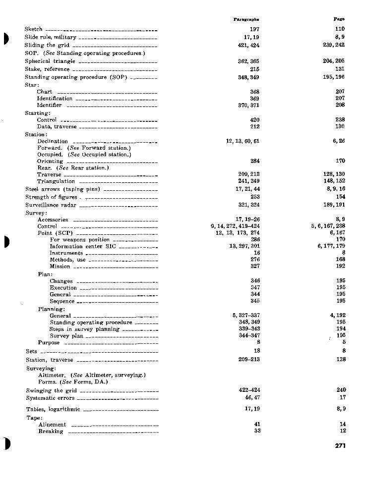
Paragraphs
Sketch Slide rule, military Sliding the grid SOP. (See Standing operating procedures.) Spherical triangle Stake, reference Standing operating procedure (SOP) Star:
Chart Identification Identifier
Starting: Control Data, traverse
Station : Declination Forward. (See Forward station.) Occupied. (See Occupied station.) .Orienting Rear. (See Rear station.) Traverse Triangulation
Steel arrows (taping pins) Strength of figures Surveillance radar Survey :
Accessories Control Point (SCP)
For weapons position Information center SIC Instruments Methods, use Mission
Plan: Changes 17' * ; „ ^ JLJJIGVU IslUU
General Sequence
Planning: General Standing operating procedure Steps in survey planning Survey plan
Purpose
Sets
Station, traverse
Surveying: Altimeter. (See Altimeter, surveying.) Forms. (See Forms, DA.)
Swinging the grid Systematic errors
197 17,19
421, 424
362, 365 215
348, 349
368 369
370, 371
420 212
12,13, 60, 61
284
209, 213 241, 249
17, 21, 44 253
321, 324
17,19-26 9,14, 272,419-424
12, 13, 173, 274 286
13, 297, 301 16
276 327
346 ojrr o*± I
344 345
5,327-337 348, 349 339-343 344-347
8 18
209-213
422-424 46, 47
Page
110 8,9
239,242
204, 205 131
195,196
207 207 208
238 130
6,26
170
128,130 148,152 8,9,16
154 189,191
8,9 5, 6,167, 238
6,167 170
6,177,179 8
168 192
195 i ntr
195 195
4,192 195 194
! 195 5
8 128
240 17
Tables, logarithmic 17,19 8,9
Tape: Alinement 41 14 Breaking 33 12
271

Paragraphs
Tape—Continued Lengths, measuring Repair
Tapeman Tapes :
Care Description
Taping Accessories Alinement Errors Night Notes Pins
Target acquisition battalion survey: Accuracy Coordination and supervision General Operations Personnel Responsibility Survey information center (SIC)
Target area: Base, survey Survey
Target set, surveying: Accessories Adjustments Setting up Leveling Maintenance Operations
Temperature : Astronomic observations Corrections, altimetry
Technical manual 5-241 series (formerly AMS TM series)
Techniques Astronomic observations Intersection Resection Traverse Triangulation
Tellurometer : Accessories Computing a distance Description Field notes General Maintenance Measuring a distance Monitoring controls Operating controls Operations Personnel Phase comparison Preset controls Principles of operation Setting up
30-32 29
30, 31, 209
28 27
30-49 17, 27
41 46-49
39 198
17,21,44
300 13, 303
300 304-315
302 13
301
290-293 290-293
166 173
167,168 169 174
171,172
382 190,192
427, 432, 434, app I app II
387-389, 403, 417 265 259
app II 238
139 151-158
139 164 138
162,163 150 147 147
145-161 159 142 147 140 148
Pase
11 10
10,11,128
10 10
10 8,10
14 17 14
111 8, 9,16
179 6,181
179 181 180
6 179
173 173
89 90 89 89 90 89
216 99,100
243, 248, 249, 253 256
216, 224, 236 165 162 256 147
67 78 67
67 84 77 73 73 72 83 71 73 70 75
272

Paragraphs
»
»
Tellurometer—Continued Setting up controls Traverse Trilatération Tuning
Tension handle Terrain, effects of, on survey operations _ Tests for aiming circle Theodolite; T2 (mils) :
Accessories Adjusting for parallax Adjustments Care and maintenance Circle-reading system Description Horizontal angles Leveling Reading scales Setting up Taking position Vertical angles
Theodolite, T-2 (Sexagesimal): Adjustments Circle reading Description Horizontal angles Reading scales Vertical angles
Theodolite, T-16: Accessories Adjusting for parallax 1 Adjustments Care and maintenance Circle reading Description Horizontal angles Leveling Reading scales Setting up Taking position Vertical angles
Thermometers in psychrometer
Three-point resection. (See Resection.)
Time: Apparent Available for survey operations Mean Of altimeter observation Of astronomic observation Sidereal Signals Solar Standard Zone corrections
Training, survey
Transformation, azimuth and coordinates
Transit: Accessories
Pag:«
147 160 161 149
73 83 84 76
17,22,42 336
8, 9,15 194
66 28
108 54 113 56
125-130 62 122-124 61 115-117 56
108 54 120 58 112 56
115-117 56 109' 55 120 58 121 61
137 66 133 65 132 65 136 66
133,134 65 136 66
88 94
102-107 99-101
96, 97 88 98 92 96
89-91 98 98
182,184,192
45 48 51 51 48 45 49 47 48 47 49 49
95, 97,100
361 278, 282, 328, 359
359, 399 187, 194, 195
381, 399 356, 360 380, 399
356 359 380
338
431-437
204 168,169,193, 203
203, 224 98, 104
216,224 200, 203
215 200 203 215
194
248
30
» 68
273

Paragraphs Paff«
Transit—Continued Adjusting for parallax Adjustment of angles Adjustments Care and maintenance Components Description Horizon closure Horizontal angles Leveling Scales Setting up Vertical angles
Transit time
Transmission of direction
Traverse : Accuracy
Ratio Adjustment Coordinate computations Definition Directional Error, radial Field notes Height computations Party Scale factor Starting data Stations Techniques Tellurometer Types
Triangle, astronomic (PZS)
Triangle, error of closure
Triangles, chain of
Triangulation : Accuracy
Checks Angular limitations Base measurement Choice of side Computations Definition Error of closure Field notes Height computations Quadrilaterals Reconnaissance Schemes Strength of figures Techniques
Trig: List
Trigonometric leveling
Tripod, ranging pole
True azimuth
Two-point resection. (See Resection.)
72 77
82-87 79-87
68 68 77
74,77 71
73, 76 69, 70 75, 78
155
408, 411
6, app II 227
229-233 218-223
207 208 227 198
220, 223 209 221 212 213
app II 160 208
361-366, 413, 415, 416
247
237,243, 245
238,'app II 241
242,246 app II 241, app II
242, 246 248, 249
237 247 199 249
250-256 276 250
253, 254 238
9, 297, 301
260, 267, 262
26
390, 392
34 I 38 ^ 41 40 30 30 38
35, 38 33
34,38 33
36, 39
81
230, 232
4,256 141 142 132 127 127 141 111
133,134 128 134 130 130 256
83 4 127
204-207, 234, 235
149
147,149
147, 256 148
148,149, 256 148, 256 148,149
152 147 149 111 152 153 168 153 154 147
5,177,179
162,165,162
9
217, 220
274 c

Paragraphs
Use of survey methods
Vernal equinox Vernier(s) Vertical angles
Determining, with theodolite. (See The- odolite.)
Measuring, with: Aiming circle. (See Aiming circle M2.) Transit. (See Transit.)
Vertical scales. (See Scales, reading.)
Weapons position, field artillery Weather:
Considerations in altimetry Effects of, on survey operations
Zenith Zone to zone transformation
276
352 73, 74
57, 223
Paffe
168
197 34,35
24,134
286
187 337
354, 362 431-437
170
98 194
199, 204 248
275

BY ORDER OF THE SECRETARY OF THE ARMY :
Official :
G. H. DECKER, General, United States Army,
Chief of Staff. R. V. LEE,
Major General, United States Army, The Adjutant General.
Distribution : Active Army:
NG: Same as Active Army except allowance is one copy to each unit except TOE 1-7, 1-17 (1); 6-100, 6-300 (4); 6-401, 6-501, 7-2, 17-2 (2).
USAR: Same as Active Army except allowance is one copy to each unit. For explanation of abbreviations used, see AR 320-50.
DCSPER (2) ACSI (2) DCSOPS (2) DCSLOG (2) ACSRC (2) CRD (1) COA (1) CINFO (1) TIG (1) TJAG (1) TPMG (1) Tech Stf, DA (1) ARADCOM (2)
ARADCOM Rgn (1) LOGCOMD (1) Armies (5) Corps (3) Div (2) Div Arty (3) Bde (1) FA Gp (5) FA Bn (5) USAAMS (900) Units organized under following TOE : 6-37 (2) 6-577 (5)
¿T U. S. GOVERNMENT PRINTING OFFICE: 1961 59877B/O002A
276

4605
83
0-5
8
(Fa
ce
p.
27
6)
WORLD STAR CHART
SOTT». I ■ . ! ■ ■ ^ ■ I ■ W i I i I i .fhi-rrr
80°
70°
60°
50°
40e
30’
10'
0e
10e
20»
50°
70°
80’
90‘
4- + + + VernOl Eau
++
+
\l
Fbmalhout -O
y'QRUS
9'' 'V®i Al Nair
eneb
/ \
+ + • +
+
Cl / AlMir \ j
AC UILA ®
AOUARI JS ^
l(Octantis)
_a u i t I i i
N---. +-
Êfomin
âVego
_±_i.
V^M i .^rrn^ i I i i I r
i é>—
IERCULIES
"+"f i
Rosologui
OPHlUCh
Nunkj ^ ßC^
SAGITTARIUS
Küus Âust
7 I haute (3g
© -e
JÍ "^Alphecci \
CORONA
US V
•"¡kïbiK
^ A/üai
ARÀ\
irts O
„-'""TRI
( Alpha) Tri (Tri Autt)
24h 23h 22h 21h 20h 19h 18h 17 J_LO.
üfesK „ .KINOR,''
^S) Kochab
! 0ÇOTES \
4-%
+ -b '''
BOREALIS
lAthald ( 3enetnasch)
/ * \ +LlfeRA \ \
LUPUp/
> .
T 131
I—♦- ! Alioth
VIRGO /
+ /
>-0 Spica
flr*HYORA
j SCORPI ) (Th »la) Centauri Cei toun,Theta —0^
R J (Beio) Centauri (Centauri, Befa)
CENIA JRUS
“¡CORPUS
¿—V ( 3amrna)Caiâî ■; .
/ ( ^ruc«jGomm< ) y
/ (Beta)C ucrs V-Æ / ^ j (Cruas.Be xj Q-' ^ Crj w j
è Acrux
(Crucis,
Mil
W . n?h-,
I ? Oubhe
^Merah »_'—"
- -HE:
bola «
y /Eauinoctidl (Equator)
Autumnc i Equinox
i Upha)
I l-L-J-
iegulus
HYDRA /
Alp lord
Affîûy^
14h 13h 12h llh
SOUTH RIGHT ASCENSION
I I I I
Sh 7,1 w. 5h Sjkr 3h
I 2d Magnitude iK*.! MOTEM"
t 3d Magnitude ¡IligM) OCTiNTlSi BETA WfORIIS ® 2d or 3d Magnitude (Bright) N0T L|sTE() |N 7M6-300-O + 4th Magnitude (Dim) ANO NOT ON STAR (DENT* • ^5thMagnitude^_(Dun^___ IFIER
^Pol !u* '
+'í GEMINI
/
(Gar ima) Geminor im
OÍProcyar
© <A \ /■
Suhail !
Ä'''(Gomma) Ar^us \ ^VELA^y (Argue, Gom|no) 'I y fVelorum.Gamrr 3® • \> /r
V '¿•psilon) Araus !í(rgus, Epsiloii
9lNA) (Oarmoe, Epsilon) ' (CA
M aplocidus
■ i > i -
-VT-
Gemmorum < iamma)
(Zeta) (Aim
Sinus O--—
MAJOR j Delta) Cdnls Canis ^ajor
,-OCcr opus
I LLI-J-
Capxlla
AURIGA \
¿Eifföth
+
^•+,^1 latir,« + +
Igeux T ^
•ORIONI
\ „© \
Ononis 1®- ok\ X*\ gel
It nls.Zeta) +v® / \ LEP IS
Ma|oris © Delta)
$rtOLUMB. I
—Í +
''0-~+ Aldebaran
6b
y Mai fa
PLEIADES
+■ .. --+•
y Í ERIDAhl
I ■K,.
TRIANGULUV +
0 Hamal
~ •# Acamar
y
CASS (Gamma,
OPEIA Cassiopeioe _
®-v(Cassiop< iae.Gomma).
' ^ ^
.. ANDROMEDA
Alpheratz*^*
+
Xenial EauinoK
+CETU!
\ Der si
O Acherr
2h 1 ) 1 I v
fih 90°
\Caph/®-
V : Schedir
30°
20*
ib Kaitos Diphda)
'TÉT' +- PHOENIX '
(HyNlrustB«ta) ~ — —•
lh
80®
70®
60®
50®
30®
40®
60°
70°
80®
90®
Figure 141. World star chart
C-)
SO
UT
H
DE
CLIN
AT
ION
NO
RT
H (♦)

3000015629

I
I
I

I
«
V > 1
3000
0156
29


![MHIMWI FM 23-8 Copy 3 DEPARTMENT OF THE ARMY FIELD … Arms/fm23_8... · 2008. 3. 24. · 7.62MM, M14 AND M14E2 HEADQUAR'ERS, DEPARTMENT OF THE ARMY MAY 1965 *FM 23-8 FIELD MANUAL]](https://static.documents.pub/doc/80x56/60d4da8b7cb7421439038eb9/mhimwi-fm-23-8-copy-3-department-of-the-army-field-armsfm238-2008-3-24.jpg)


